

NEC versa 4000 schematic

SOLD BY laptopia2005 DO NOT RESELL!!
PROPRIETARY NOTICE AND LIABILITY DISCLAIMER
The info rmat ion dis closed in this doc ument , including a ll desig ns and related mate rials, is
the valuable propert y of NEC Cor p oration (NEC) and/or its licensors. NEC and/or its licensors, as appropriate, r eserve all patent, copyright and other proprietary rights to t his document, including all design, manufacturing, reproduction, use, and sales rights thereto, except
to the extent said rights are expressly granted to others.
The NEC product(s) discussed in this document are warranted in accordance with the terms
of the Warranty Statement accompanying each product. However, actual performance of
each such pro duct is dependent upo n fact ors such as system configuration, cust omer data,
and operator control. Since implementation by customers of each product may vary, the
suitability of specific product configurations and applications must be determined by the
customer and is not warranted by NEC.
To allow for design and specification improvements, t he information in t his document is
subject to change at any t ime, without not ice. Repr oduction of this do cument o r portions
thereof without prior written approval of NEC is prohibited.
Fa stFacts , and NEC SVG A, are U.S. tr ademarks of NEC Technologies, Inc.
All other p roduct, brand, or tra de names used in t his public ation a re the tr ademarks or regis tered
tr ademarks of their respective trademark owners.
First Printing — August 1995
Copyright 1995 Copyright 1995
NEC Technologies, Inc. NEC Corporation
1414 Massachusetts Avenue 7-1 Shiba 5-Chome, Minato-Ku
Boxborough, MA 01719 Tokyo 108-01, Japan
All Rights Reserved All Rights Reserved
SOLD BY laptopia2005 DO NOT RESELL!!

SOLD BY laptopia2005 DO NOT RESELL!!
Preface
This service and reference manu al contains the technical information necessary t o set up,
and maintain the NEC Versa™ 4000 Series noteboo k systems. It also provides hardware
and interface information fo r user s who need an overview of the computer system design.
The manual is written for NEC-t r ained customer engineers, system analysts, service center
personnel, and dealers.
Please refer to the t raining module provided on CD-ROM for system disassembly/assembly
procedures.
The manual is organized as follows:
Section 1 Technical Information, pr ovides an overview of the hardware and int er face
components. System specifications are listed including computer dimensions, weight, environment, safety compliance, power co nsumption, and system memory specifications.
vii
Section 2 Setup and Operation, takes t he user from unpacking t o setup and operation.
The section includes a description of operat ing controls, setting parameters and accessing
the NEC bulletin boar d syste m ( B B S).
Section 3 Illustrated Pa rts Breakdown (IPB), pro vides an explo ded- view diagram o f
the NEC Versa 4000 series system and part numbers.
Appendix A Connector Locations and Pin Assignments, provides a lis t of the main
board internal connector pin assignments and a list of external pin assignments.
An Index is included fo r convenience.
SOLD BY laptopia2005 DO NOT RESELL!!

SOLD BY laptopia2005 DO NOT RESELL!!
Contents
Preface.........................................................................................................................vii
Abbreviations............................................................................................................... ix
Section 1 Technical Information
Hardware Overview..................................................................................................... 1-2
Liquid Crystal Display (LCD)................................................................................ 1-2
CPU Board........................................................................................................... 1-3
I/O Board............................................................................................................. 1-3
Sound Bo ard ......................................................................................................... 1-3
Infrared (IR) Front Assembly, Rear Assembly....................................................... 1-4
Battery Pack......................................................................................................... 1-4
iii
CMOS Battery...................................................................................................... 1-4
Bridge Battery...................................................................................................... 1-4
PCMCIA Slots...................................................................................................... 1-4
Diskette Drive and the NEC VersaBay II .............................................................. 1-5
Keyboard.............................................................................................................. 1-5
NEC VersaGlide................................................................................................... 1-5
System Memory........................................................................................................... 1-5
Memory Map........................................................................................................ 1-6
System Video............................................................................................................... 1-7
Parallel Interface.......................................................................................................... 1-11
Serial Interface............................................................................................................. 1-12
NEC Versa 4000 Series Chip Set ................................................................................. 1-12
Intel Pentium P54LM............................................................................................ 1-12
Cache Controller, Address Logic, Data Controller................................................. 1-13
System Logic, IDE Interface, Peripheral Controller ............................................... 1-13
Flash ROM........................................................................................................... 1-13
ROM BIOS.................................................................................................... 1-14
VGA Controller.................................................................................................... 1-14
Video Controller Architecture........................................................................ 1-15
Diskette Contr oller , S er ial Interface, Parallel Inter face .......................................... 1-15
Keyboard Cont ro ller ............................................................................................. 1-15
PCMCIA Controller.............................................................................................. 1-15
Interrupt Co ntrollers ............................................................................................. 1-16
SOLD BY laptopia2005 DO NOT RESELL!!

SOLD BY laptopia2005 DO NOT RESELL!!
iv Contents
Power Management Overview ..................................................................................... 1-17
System Power Management .................................................................................. 1-17
Local Power Management..................................................................................... 1-18
Plug and Play............................................................................................................... 1-18
Specifications............................................................................................................... 1-19
Section 2 Setup and Operation
Unpacking the System.................................................................................................. 2-1
Hardware Setup........................................................................................................... 2-1
Cable Connections................................................................................................ 2-2
Operating Controls ...................................................................................................... 2-3
Status Bar............................................................................................................. 2-4
Status Icons ................................................................................................... 2-5
Battery Status ................................................................................................ 2-5
Function Keys (Fn Keys)....................................................................................... 2-6
Smart Po wer Switch............................................................................................. 2-6
Dip Switch............................................................................................................ 2-7
Power-on Self-Test (Post)............................................................................................ 2-8
POST Errors......................................................................................................... 2-9
Set up Utility ................................................................................................................ 2-10
Accessing Setup .................................................................................................... 2-10
With an Error at POST .................................................................................. 2-10
With No Errors at POST................................................................................ 2-10
Setup Screen......................................................................................................... 2-11
Setup Keys..................................................................................................... 2-11
Changing/Setting Parameter Set t ings............................................................................ 2-11
Parameter Options ....................................................................................................... 2-13
Parameter Descriptions......................................................................................... 2-14
Time/Date...................................................................................................... 2-14
Drives............................................................................................................ 2-14
Peripherals..................................................................................................... 2-14
Security ......................................................................................................... 2-15
Power Savings............................................................................................... 2-15
Security Options.......................................................................................................... 2-16
System Password.................................................................................................. 2-16
Using the System Password............................................................................ 2-16
Keyboard Lock Hot key......................................................................................... 2-17
SOLD BY laptopia2005 DO NOT RESELL!!

SOLD BY laptopia2005 DO NOT RESELL!!
BIOS Updat e Utility (BU U)......................................................................................... 2-17
Precautions........................................................................................................... 2-17
Downloading the Up date Utility............................................................................ 2-17
Us ing the Upda te Utility........................................................................................ 2-18
Menu Functions.................................................................................................... 2-20
Power Sources............................................................................................................. 2-23
AC Adapter .......................................................................................................... 2-23
Battery Power....................................................................................................... 2-24
Recharging the Battery Pack.......................................................................... 2-24
Replacing the Battery Pack .......................................................................................... 2-24
Saving Battery Power ........................................................................................... 2-26
Automatic Power-Saving Features............................................................................... 2-27
Contents v
Section 3 Illustrated Parts Breakdown
Appendix A Connector Loc ations and Pin Assignments
List of Figures
1-1 NEC Versa 4000 Series System Features ....................................................... 1-1
1-2 NEC Versa 4000 Series (Rear View).............................................................. 1-2
2-1 Power and I/O Connector Locations .............................................................. 2-2
2-2 Keyboard Panel Co ntrols................................................................................ 2-3
2-3 Right Side Panel Controls .............................................................................. 2-3
2-4 Status Bar Location....................................................................................... 2-4
2-5 Status Bar Icons............................................................................................. 2-5
2-6 Dip Switch Location...................................................................................... 2-7
2-7 Dip Switch Settings........................................................................................ 2-7
2-8 Connecting the AC Adapter ........................................................................... 2-23
2-9 Battery Cover Lat ch Locatio n........................................................................ 2-25
2-10 Batter y Pack Replacement.............................................................................. 2-25
2-11 Batter y Bay Cover Replacement..................................................................... 2-26
3-1 NEC Versa 4000 Series Illustrated Parts Breakdown...................................... 3-3
A-1 System Board Connector Locations............................................................... A-1
SOLD BY laptopia2005 DO NOT RESELL!!

SOLD BY laptopia2005 DO NOT RESELL!!
vi Contents
List of Tables
1-1 NEC Versa 4000 Series System Memory Map ............................................... 1-6
1-2 CRT Display Mode (CRT only)...................................................................... 1-7
1-3 LCD Display Modes (640 x 480 TFT, Simultaneous CRT)............................. 1-9
1-4 LCD Display Modes (640 x 480 DSTN, Simultaneous CRT ) ......................... 1-10
1-5 NEC Versa 4000 Series Chip Types and Technologies ................................... 1-12
1-6 NEC Versa 4000 Series Int errupt Level Assignments..................................... 1-16
1-7 Maximum Performance Default Settings......................................................... 1-18
1-8 Specifications................................................................................................. 1-19
2-1 I/O Connector Descriptions............................................................................ 2-2
2-2 Control and Switch Functions........................................................................ 2-4
2-3 FnKey Operations.......................................................................................... 2-6
2-4 POST Error Messages.................................................................................... 2-9
2-5 Setup Key Functions...................................................................................... 2-11
2-6 System Parameter Settings............................................................................. 2-13
2-7 Automat ic Power-Saving Features ................................................................. 2-27
3-1 NEC Versa 4000 Series Field-Replaceable P arts............................................. 3-1
3-2 Option and Documentation Part Numbers...................................................... 3-4
A-1 CPU Board Connectors.................................................................................. A-1
A-2 Keyboard/Mo use Connector Pin Assignments ................................................ A-1
A-3 Serial Port Connector Pin Assignments .......................................................... A-2
A-4 CRT Connector Pin Assignments ................................................................... A-2
A-5 Parallel Printer Pin Assignments..................................................................... A-3
A-6 Expansion Connector Pin Assignments........................................................... A-4
A-7 Power Connector........................................................................................... A-8
A-8 Hard Disk Drive Connector ............................................................................ A-9
A-9 Diskette Drive Connecto r...............................................................................A-10
SOLD BY laptopia2005 DO NOT RESELL!!
SOLD BY laptopia2005 DO NOT RESELL!!
Section 1
Technical Information
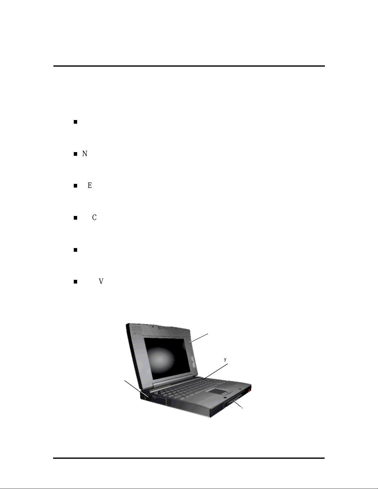
The NEC Versa 4000 series computers integrate the Intel® Pentium-75 MHz, or 90-MHz
chips. The systems offer a unique transportable unit in the follo wing configurations:
NEC Versa 4000D 75-MHz CPU, 540-MB hard disk drive, 10.4-inch Dual-
Scan Super Twisted Nematic (DSTN) color LCD, 8-MB standard RAM, 1-MB
video memory, 256-KB ROM
NEC Versa 4000C 75-MHz CPU, 540-MB hard disk drive, 10.1-inch thin-film
transistor (TFT) color LCD, 8-MB standard RAM, 1-MB video memory, 256-KB
ROM
NEC Versa 4000H 75-MHz CPU, 810-MB hard disk drive, 10.4- inch, high
resolution, thin-film t ransistor (TFT) co lor LC D, 8-MB stand ar d RA M, 1-MB
video memory, 256-KB ROM
NEC Versa 4050C 90-MHz CPU, 810-MB hard disk drive, 10.1-inch thin-film
transistor (TFT) color LCD, 8-MB standard RAM, 1-MB video memory, 256-KB
ROM
NEC Versa 4050H 90-MHz CPU, 810-MB hard disk drive, 10.4- inch, high
resolution, thin-film t ransistor (TFT) co lor LC D, 8-MB stand ar d RA M, 1-MB
video memory, 256-KB ROM
NEC Versa 4000 120-MHz CPU, 1 gigabyte (GB) hard disk dr ive, 10.4-inch
Super Video Graphics Array (SVGA) color LCD, 8-MB standard RAM, 1-MB
video memory, 256-KB ROM
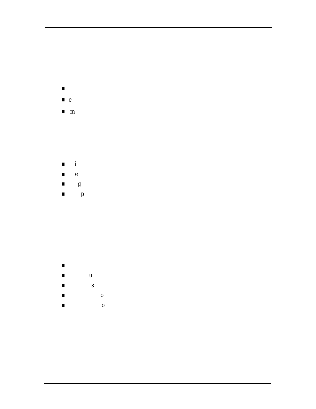
Figure Section 1-1 shows system feat ur es.
PCMCIA
Slots
LCD
Keyboard
Diskette Drive/
Figure Section 1 -1 NEC Versa 4000 Series System Features
VersaBay II
SOLD BY laptopia2005 DO NOT RESELL!!
SOLD BY laptopia2005 DO NOT RESELL!!
1-2 Technical Information
HARDWARE OVERVIEW
The base unit includes a color LCD panel, a 2 1/2-inch 540-MB, or 810-MB hard disk
drive, a 3 1/2-inch, 1.44-MB diskette drive, a battery pack, and a PS/2 compatible 83-key
keyboard. A 79-key keyboard is used fo r U. K. and Germany. T he NEC VersaGlide touchpad is positioned at the front of the keyboard, and takes the place of a mouse.
Multimedia features include built-in stereo speakers and a built - in microphone. Multimedia
port s include line-in, line-out, headphone and external microphone.
One memor y card slot is available for the addition of a 4-, 8- , 16-, o r 32- MB capacity
memory card. Two Personal Co mputer Memory Card International Association (PCMCIA)
card slots, supported by the Cirrus Logic PD6722 PCMCIA controller, allow for the addition of either two PCMCIA Type 1/Type II cards or one PCMCIA Type III card.
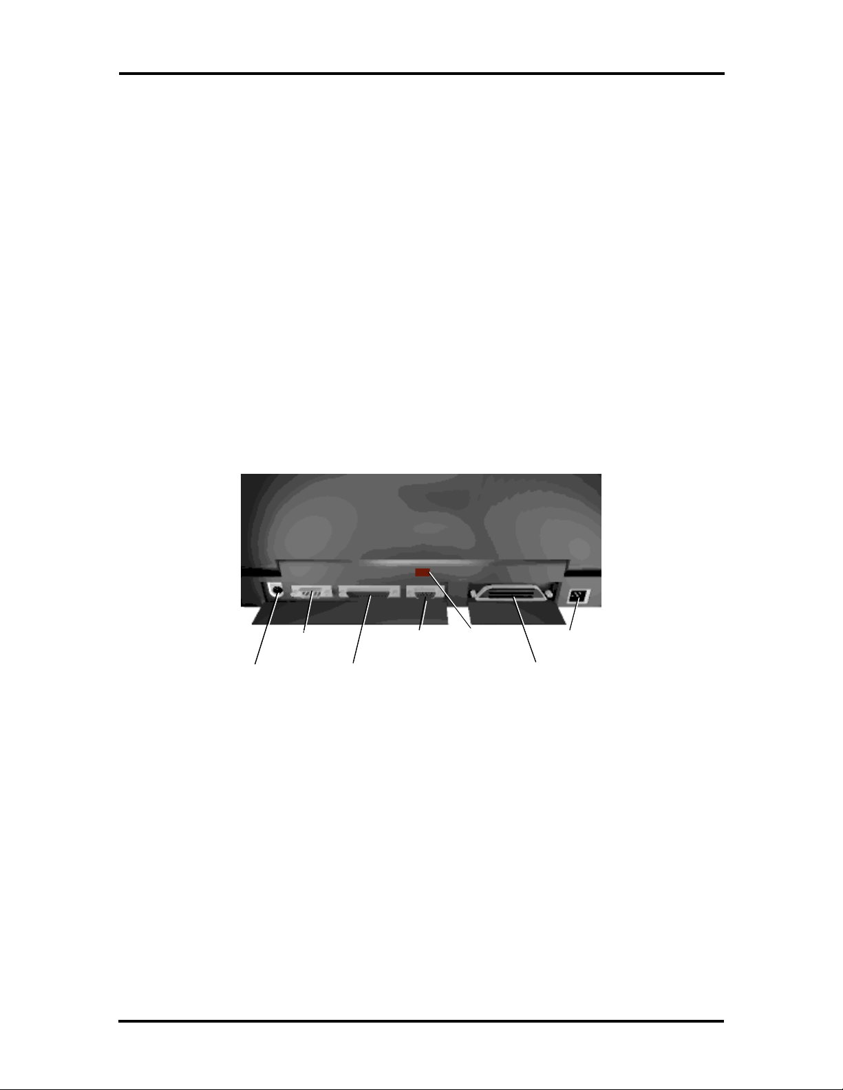
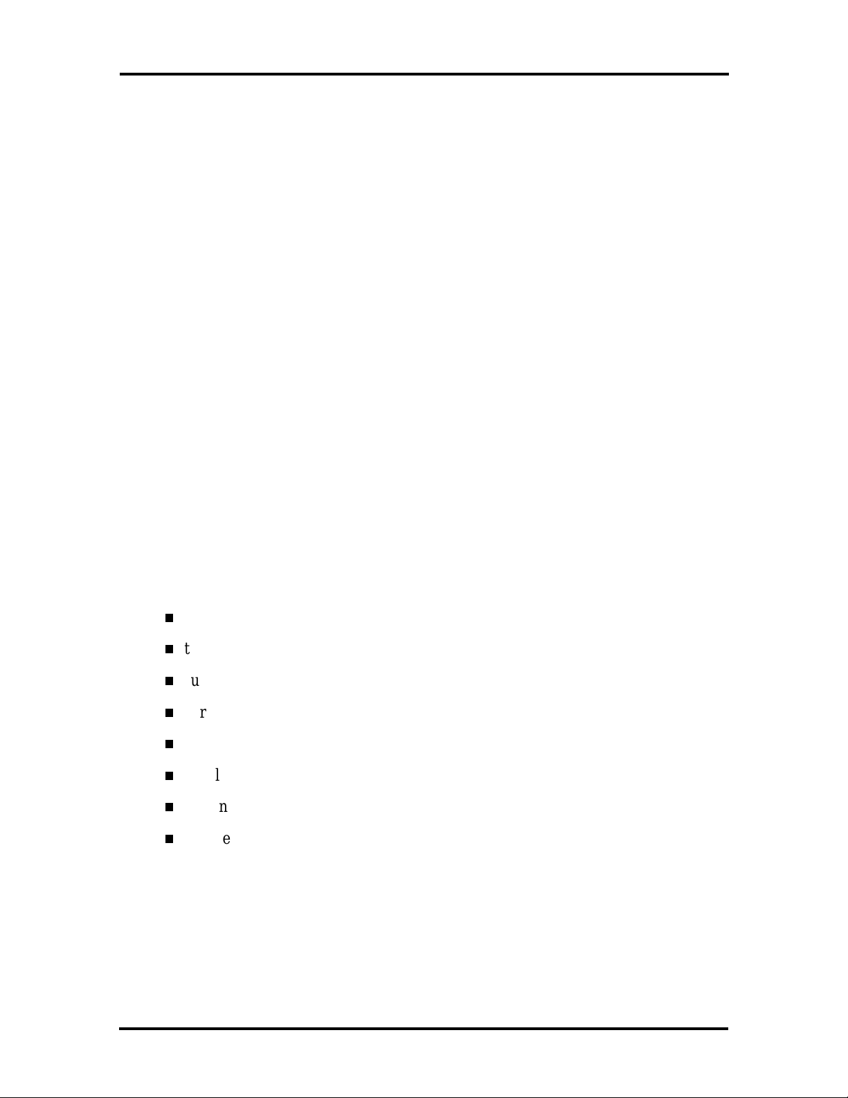
Figure Section 1-2 shows the standard I/O interface port s on the system's rear panel. These
include one 6-pin shared PS/2-style keyboard/mouse port , one 9-pin (RS-232C) serial port,
one 25-pin enhanced printer (parallel) por t, one 15-pin Super VGA CRT port, one Infrared
(IR) port, one expansion connector, and one 4-pin power connector port.
Seria l Port
Mouse/
Key board Port
CRT Port
Enhanced
Parallel Port
IR Port
Power Port
Expansion Port
Figure Section 1 -2 NEC Versa 4000 Series (Rear View)
Liquid Crystal Display (LCD)
The system integrates a built-in LCD. The LCD supports VESA Local (VL) bus video. T he
LCD operates with the Chips & Technologies 65545B1-5 VGA controller. The controller
supports Super VGA. For more information on the 65545B1-5 or 65545B2-H VGA controller, read the description provided in the NEC Versa 4000 Series Chip Set subsection.
SOLD BY laptopia2005 DO NOT RESELL!!

SOLD BY laptopia2005 DO NOT RESELL!!
The NEC Versa 4000 series syst em features the following types of LCDs.
TFT — 10.1- in ch thin-film trans ist or backlit color LC D, 0. 32 mm dot pitch, 1 8bit digital interface, 640 x 480 resolution, 256,000 colors.
DSTN — 10.4-inch dual-scan super twisted nematic color LCD, 0.33 mm do t
pitch, 16-bit digital interface, 600 x 480 resolution, 256,000 colors, (64K colors
on an external CRT).
High Resolution TFT — 10.4-inch thin film tr ans ist or color LCD , 0 .2 6 mm dot
pitch, 18-bit digital interface, 800 x 600 resolution, 256,000 colors, (64K colors
on an external CRT).
In addition, the CRT port on the system's rear panel allows the user to connect an optional
monochrome or color external display to the syst em. The computer suppo r ts the LCD and
extern al display simult ane ously.
Technical Information 1-3
Pow er-saving fea tures for co ntrolling the LC D's bac klighting include the ROM-b ase d hot
key Fn F5, and Auto Set up power management sett ings. See Section 2, Setup and Operation, for information on using these settings. In addition, the automatic LCD stat us sense
feature conserves the backlight . When the LCD is clo sed the backlight shuts o ff, saving
battery power.
CPU Board
The CPU board (75 Mhz, 90 MHz or 120 MHz) CPU board is an L-shaped board situated
next to the audio ports. In addition to the CPU, this board houses the bridge battery and
speaker. It controls impo r tant functions including power management, direct dr ive bus interface and memor y management.
I/O Board
The I/O board (G8TUP ) contains per ipheral subsystems including serial, par allel and video
port s. I t is lo cated underneath the sound board.
I/O board specifications are listed in Table Section 1-8 at the end of this section.
Sound Board
The sound board (G8UNA) provides the NEC Versa 4000 series system with its audio capabilities via line-in/line-out jacks, an d head phone/mic roph one jacks. It is situated on top of
the I/O board.
SOLD BY laptopia2005 DO NOT RESELL!!

SOLD BY laptopia2005 DO NOT RESELL!!
1-4 Technical Information
Infrared (IR) Front Assembly, Rear Assembly
Two IR assemblies are connected to the I/O board via connectors P10 and P11 respectively.
One is located on the front of the NEC Ver sa, the second one is located on the rear of the
NEC Versa.
Each IR assembly consists of a small board with infrared LEDs. T he board allows the NEC
Versa 4000 series computer to co mmunicate with other infrared- r eady computers. Fo r example, the infrared po r ts allow the user to transfer files between the NEC Versa and an IRequipped desktop, or print to an IR-equipped printer without using cables.
The NEC Versa 4000 series syst em ships with t he rear I R assembly disabled and the front
IR assembly disabled. When the NEC Versa 4000 is docked to the optional NEC Versa
Docking Station 4000, the rear IR assembly is automatically disabled, and the front enabled.
Battery Pack
The system uses a rechargeable lithium-ion (Li-ION) batt er y as its transient power source.
The battery pack installs in the compartment next to t he st andard diskette drive on the bottom of the Versa 4000. The battery uses 10.8 volts with a 2500 mAh capacity.
The battery pack powers the NEC Versa 4000 for approximately 5 hours with Power Management or 2.5 hours without Power management. In addition, the battery pack lets the
user know how much battery power is available via t he LEDs o n t he front of the system, or
the battery gas gauge in the power panel.
When bat tery power is getting low, connect the AC adapter t o a wall o utlet and recharge
the batter y. It takes 2.5 hours t o recharge the batter y pack when the system is power ed off,
(Quick Charge). It takes 2.5 hours to recharge the batter y while the system is po wer ed on,
(No rma l Charg e).
CMOS Battery
The lit hium battery (3.0 Volts, 280 mAh capacit y) is attached to connector P12 on the CPU
board. It pr ovides battery backup and prevents dat a loss in the system’s complementary
metal oxide semiconductor (CMOS) RAM. T h is memory area contains informat ion on the
sys te m’s configurat ion like date , time, drives, and memory. The CMOS b at tery lasts approximate ly two years.
Bridge Battery
The bridge battery saves the memory contents and system status for up to 5 minutes while
in Suspend mode. I t is connected to the CPU board via P8. The AC adapter maintains voltage in the br idge batter y when the system is powered o n o r off. T he bridge battery provides
6 Volts, 60 mAH.
SOLD BY laptopia2005 DO NOT RESELL!!

SOLD BY laptopia2005 DO NOT RESELL!!
PCMCIA Slots
The Versa 4000 provides a 5 volt, or 3.3 volt interface for either two Type I/Type II
PCMCIA cards, or one Type III PCMCIA card.
Diskette Drive and the NEC VersaBay II
A standard 1.44-MB diskette dr ive comes installed in the VersaBay II slot on the front of
the system. The VersaBay II expansion slot allows the user to r eplace the standard diskette
drive wit h a number of different NEC o ptions including a CD-ROM reader, a second battery pack, or an additional har d disk drive using t he release latches on the bottom of the
unit.
Keyboard
The built-in, 83-key keybo ard (U.S) or 79-key keyboard (UK and Germany) uses the standard QWERTY format. The keyboard provides 12 function keys and 8 cursor co nt r ol keys,
with an Fn key for ROM-based key functions. The numeric keypad is embedded in the standard key layout.
Technical Information 1-5
NEC VersaGlide
The NEC VersaGlide is a built-in mechanism that functions as the system’s mouse. I t contro ls the on-screen po inter (cur sor). To use the VersaGlid e, glide your finger across the
NEC VersaGlide pad, and the cursor follows. The buttons on either side of the NEC VersaGlide allow the user to select or deselect menu items. Tap and double-tap are supported
on the VersaGlide pad.
The NEC VersaGlide is the system's default pointing device unless a PS/2 mouse is installed. If an ext er nal mouse is installed, then the NEC VersaGlid e is deactivated. A serial
mouse is not supported.
SYSTEM MEMORY
The system board provides 8-MB of standard r andom access memory (RAM).The NEC
Versa 4000 operat es with 4 banks. Banks 0 to 1 are used for the standard 8-MB (with interleaved access support). Banks 2 to 4 are used for memory expansion (without interleaved
access support).
Optional memory cards with a value o f 4-, 8- , 16- , or 32-MB can be added to increase system memory up to a maximum of 40-MB. In addition, 256 KB of r ead- only memo r y
(ROM), 1 x 28F020, enables the system BIOS to be flashed.
Cache RAM is available with L1 write-back access support pr ovid ing 8 KB for code, 8 KB
for data. L2 write-through access support pr oviding 256 KB.
SOLD BY laptopia2005 DO NOT RESELL!!

SOLD BY laptopia2005 DO NOT RESELL!!
1-6 Technical Information
Memory Map
The system supports system and video shadowing, both contro lled through complementary
metal oxide semiconductor (CMOS). T he system supports BIOS as a cacheable area with
writ e prot ection. Table Sect ion 1- 1 lists the sys tem's memo ry map.
To view a more complete breakdown, and to det er mine available space for the addition of
drivers etc., type
Table Section 1-1 NEC Versa 4000 Series System Memory Map
Memory Space Size Function
MSD
at the DOS pro mpt and press
Enter
.
0027FFFFh00C0000h
000BFFFFh00010000h
000FFFFFh000F0000h
000EFFFFh000CA000h
000C9FFFh000C0000h
000BFFFFh000A0000h
0009FFFFh0000000h
40 MB Reserv ed for Extended Memory
8 MB
64 KB ROM BIOS
152 KB Upper Mem or y B lock (UMB)
40 KB Video RO M B IOS
128 KB Video Memory
640 KB Conventional Memory
Base Memory
SOLD BY laptopia2005 DO NOT RESELL!!
SOLD BY laptopia2005 DO NOT RESELL!!
SYSTEM VIDEO
The system's LCD o per ates using the Chips and Technologies 65545B1- 5 or 65545B2-H
VGA Controller. Video signals tr avel from the controller through the system's 15-pin DSUB connector using 5 volt s.
System video integrat es a 32- bit VL-bus interface using local bus video. The system ships
with 1 MB Video RAM (VRAM). It also support s video modes up to 1024 x 768 with 256
colors in CRT mode.
Table Sect ion 1- 2 lists CRT display modes..
NOTE:
with the letter I in the table below.
Table Sec tion 1-2 CRT Display Mode (CRT only)
Interlaced video modes are represented
Technical Information 1-7
Mode
(Hex)
0, 1 Text 16 40x25 320x200 8x8 70
0*, 1* Text 16 40x25 320x200 8x14 70
0**, 1** Text 16 40x25 360x400 9x16 70
2, 3 Text 16 80x25 640x200 8x8 70
2*, 3* Text 16 80x25 640x350 8x14 70
2**, 3** Text 16 80x25 720x400 9x16 70
4,5* Graphics 4 40x25 320x200 8x8 70
6 Graphics 2 80x25 640x200 8x8 70
7* Text Mono 80x25 720x350 9x14 70
7** Text Mono 80x25 720x400 9x16 70
D Planar 16 40x25 320x200 8x8 70
E Planar 16 80x25 640x200 8x8 70
F Planar Mono 80x25 640x350 8x14 70
10 Planar 16 80x25 640x350 8x14 70
Display
Mode
Colors
Text
Display Resolution Font
Refresh
Rate
11 Planar 2 80x30 6400x480 8x16 60
12 Planar 16 80x30 640x480 8x16 60
12*** Planar 16 80x30 640x480 8x16 74
13 Packed
Pixel
20 4-bi t linear 16 80x30 640x480 8x16 60
256 40x25 320x200 8x8 70
SOLD BY laptopia2005 DO NOT RESELL!!
SOLD BY laptopia2005 DO NOT RESELL!!
1-8 Technical Information
Table Sec tion 1-2 CRT Display Mode (CRT only)
Mode
(Hex)
22 4-bi t linear 16 100x37 800x600 8x16 60
24 4-bi t linear 16 128x48 1024x768 8x16 60
24I 4-bit linear 16 128x 48 1024x768 8x16 43
30 8-bi t linear 256 80x30 640x480 8x16 60
30*** 8-bit linear 256 80x30 640x 480 8x16 74
32 8-bi t linear 256 100x37 800x600 8x 16 60
32*** 8-bit linear 256 100x37 800x600 8x16 74
34 8-bi t linear 256 128x48 1024x768 8x16 60
34I 8-bit linear 256 128x48 1024x768 8x16 43
40 15-bit
41 16-bit
50 24-bit
Display
Mode
linear
linear
linear
Colors
32K 80x30 640x480 8x16 60
64K 80x30 640x480 8x16 60
16 80x30 640x480 8x16 55
Text
Display Resolution Font
Refresh
Rate
60 Text 16 132x25 1056x400 8x16 68
61 Text 16 132x50 1056x400 8x16 68
6A, 70 Planar 16 100x37 800x600 8x16 60
6A***
70***
72, 75 Planar 16 128x48 1024x768 8x16 60
72I, 75I Planar 16 128x48 1024x768 8x16 43
78 Packed
79 Packed
79*** Packed
7C Packed
7C*** Packed
Planar 16 100x37 800x600 8x16 74
256 80x25 640x400 8x16 70
Pixel
256 80x30 640x480 8x16 60
Pixel
256 80x30 640x480 8x16 74
Pixel
256 100x37 800x600 8x16 60
Pixel
256 100x37 800x600 8x16 74
Pixel
SOLD BY laptopia2005 DO NOT RESELL!!
SOLD BY laptopia2005 DO NOT RESELL!!
Table Sec tion 1-2 CRT Display Mode (CRT only)
Technical Information 1-9
Mode
(Hex)
7E1 Packed
7E1 Packed
*EGA Extension
**VGA Extension
***High Refresh Modes
Display
Mode
Pixel
Pixel
Colors
256 128x48 1024x768 8x16 43
256 128x48 1024x768 8x16 60
Text
Display Resolution Font
Refresh
Rate
Table Section 1-3 lists 640 x 480, TFT simu ltaneous LCD/CRT display modes.
Table Sec tion 1-3 LCD Display Modes (640 x 480 TFT, Simultaneous CRT)
Mode
(Hex)
0,1 Text 16 40x25 320x200 8x8 60
2,3 Text 16 80x25 640x200 8x8 60
Display
Mode Colors
Text
Display Resolution Font
Refresh
Rate
0*, 1* Text 16 40x 25 320x350 8x14 60
2*, 3* Text 16 80x 25 640x350 8x14 60
0**, 1** Text 16 40x25 320x400 8x16 60
2**, 3** Text 16 80x25 640x400 8x16 60
4, 5 Graphics 4 40x25 320x200 8x8 60
6 Graphics 2 80x25 640x200 8x8 60
7* Text Mono 80x25 640x350 8x14 60
7** Text Mono 80x25 640x400 8x16 60
D Planar 16 40x25 320x200 8x8 60
E Planar 16 80x25 640x200 8x8 60
F Planar Mono 80x25 640x350 8x14 60
10 Planar 16 80x25 640x350 8x14 60
11 Planar 2 80x30 640x480 8x16 60
12 Planar 16 80x30 640x480 8x16 60
13 Packed
Pixel
20 4-bit
linear
256 40x25 320x200 8x8 60
16 80x30 640x480 8x16 60
SOLD BY laptopia2005 DO NOT RESELL!!
SOLD BY laptopia2005 DO NOT RESELL!!
1-10 Technical Information
Table Sec tion 1-3 LCD Display Modes (640 x 480 TFT, Simultaneous CRT)
Mode
(Hex)
30 8-bit
40 15-bit
50 24-bit
41 16-bit
78 Packed
79 Packed
*EGA Extension
**VGA Extension
Display
Mode Colors
256 80x30 640x480 8x16 60
linear
32K 80x30 640x480 8x16 60
linear
16 M 80x30 640x480 8x16 55
linear
64K 80x30 640x480 8x16 60
linear
256 80x25 640x400 8x16 60
Pixel
256 80x30 640x480 8x16 60
Pixel
Text
Display Resolution Font
Refresh
Rate
Table Section 1-4 lists LCD display modes, 640 x 480 DSTN, simult aneous CRT display
modes.
Table Section 1-4 LCD Display Mode (640 x 480 DSTN, Simultaneous CRT
Display)
Mode
(Hex)
0, 1 Text 16 40x25 320x200 8x8 60
2, 3 Text 16 80x25 640x200 8x8 60
0*, 1* Text 16 40x25 320x350 8x14 60
2*, 3* Text 16 80x25 640x350 8x14 60
0**, 1** Text 16 40x25 320x400 8x16 60
2**, 3** Text 16 80x25 640x400 8x16 60
4,5 Graphics 4 40x25 320x200 8x8 60
6 Graphics 2 80x25 640x200 8x8 60
7* Text Mono 80x25 640x350 8x14 60
7** Text Mono 80x25 640x400 8x16 60
D Planar 16 40x25 320x200 8x8 60
E Planar 16 80x25 640x200 8x8 60
Display
Mode
Colors
Text
Display Resolution Font
Refesh
Rate
SOLD BY laptopia2005 DO NOT RESELL!!
SOLD BY laptopia2005 DO NOT RESELL!!
Table Section 1-4 LCD Display Mode (640 x 480 DSTN, Simultaneous CRT
Display)
Technical Information 1-11
Mode
(Hex)
F Planar Mono 80x25 640x350 8x14 60
10 Planar 16 80x25 640x350 8x14 60
11 Planar 2 80x30 640x480 8x16 60
12 Planar 16 80x30 640x480 8x16 60
13 Packed
20 4-bit
30 8-bit
78 Packed
79 Packed
*EGA Extension
**VGA Extension
Display
Mode
Pixel
linear
linear
Pixel
Pixel
Colors
256 40x25 320x200 8x8 60
16 80x30 640x480 8x16 60
256 80x30 640x480 8x16 60
256 80x25 640x400 8x16 60
256 80x30 640x480 8x16 60
Text
Display Resolution Font
Refesh
Rate
PARALLEL INTERFACE
The system's par allel interface integrates National Semiconductor’s PC87334 chip. I t uses a
25-pin D-subconnector. T he por t is lo cated on the system's r ear panel.
The modes of operation available fo r a PC87334 chip are
compatibility mo de
nibble mode
byte mo de
En hanced Capa bilit ied Port ( EC P)
Enhanced Parallel Port (EPP).
The user selects between three parallel interface modes using Aut o Setup. T hese include
un idirectiona l, bidirectiona l or enhanced. Unid ire ctional mode se nds data output from t h e
standard ISA port only. Bidir ectional mode sends data using the standard ISA port or PS/2
technology. Enhanced mode enables high speed dat a transmission to occur using eit her the
un idirectiona l or bid irectional modes.
SOLD BY laptopia2005 DO NOT RESELL!!
SOLD BY laptopia2005 DO NOT RESELL!!
1-12 Technical Information
The parallel port address is 378h and the interrupt level is IRQ07. Pin locations for the parallel interface are listed in Appendix A.
SERIAL INTERFACE
The RS-232C serial port is a 9-pin connector on t he system’s rear panel. T he serial port
consists of a 16550 compatible serial po r t controller with a programmable baud rate up to
115,200 bps. The serial po r t connects an RS-232C device or an external modem. The serial
port addr ess is 3F8h and the inter r upt level is IRQ04.
NEC VERSA 4000 SERIES CHIP SET
Refer to Table Section 1-5 for a quick summary of the chip types used in the system. See
the Abbreviations section at the beginning of this manual for a translation of chip technologies.
Table Sec tion 1-5 NEC Versa 4000 Series Chip Types and Technologies
Chip Manufacturer Description Technology
Intel Pentium P54LM Intel 75 MHz, 90-MHz, 120-MHz
CPU
PT80C732 or
PT80C733
PT86C718 Pico Power System Logic AT Base,
N28F020-150 Intel 256k x 8 Flash ROM 32-pin PLCC
C&T65545B1-5 Chips &
PC87334 National
M38813E4HP Mitsubishi Keyboard Controller 64-pin TQFP
PD6722 Cir r us Logi c PCMCI A Controller 208-pin TQFP
ES688S ESS Technology Sound Integrated Circ uit 100-pin TQFP
Pico Power Cache Controller, Address
Logic and Data Contr oller
IDE Interface, Peripheral
VGA Controller 208-pin Q FP
Technologi es
Diskette Controller , IDE,
Semiconductor
Parallel Interface
320-pin TCP
176-pin TQFP and
144-pin TQFP
176-pin TQFP
100-pin FQFP
Intel Pentium P54LM
The 75 MHz, 90 MHz or 120 MHz Intel Pentium microprocessor used in the NEC Versa
4000 series computer is built on Intel’s advanced 3.3V BiCMOS silicon tech nology. The
CPU has on-ch ip dual-processing, a local multiproc ess or interrupt cont roller, and power
management features. NE C adopted the chip specifically for its pipelined Floating Point
Unit (FPU), and local inte rr upt management.
SOLD BY laptopia2005 DO NOT RESELL!!
SOLD BY laptopia2005 DO NOT RESELL!!
Cache Controller, Address Logic, Data Controller
The Golden Gate PT80C732 and PT80C733 Pico Power contro ller provides a dual-chip
struct ur e that connect the Pentium processor to the industry-standard 486 bus. The chip increase s dat a reliab ility by integrating the following:
8-level write buffer
extends battery life and efficient thermal management
improved performance for DRAM and VL bus peripherals.
System Logic, IDE Interface, Peripheral Controller
The PT86C718 Pico Power chip consists of a 176-pin thin-quad flat-package. This chip
contro ller supports fast graphics and I /O pr ocessing. T he system lo gic controller adds t he
follo wing features:
Technical Information 1-13
built- in level 2 cache controller
integrated active power management
integrat ed b att ery mana gement
high perfo rmance DRAM controller.
Flash ROM
The N28F020 flash ROM is a 32-pin, plastic lead chip carrier (PLCC). The chip allows easy
updates to the system's BIOS if needed. More specifically, the ROM is flashed electronically, in st alling th e late st BIOS revisions to the system. I t is poss ib le to re program t he B IOS
up to 100,000 times. See Sect ion 2, Setup and Operat ion, for BIOS update pr ocedures.
The N28F020 provides the system upgrade capability as well as the following:
256 KB memory
Quick-Pulse Prog ramming Algorithm
150 nanoseconds (ns) maximum access t ime
ET OX Nonvolatile flash te chnolo gy
CMOS low power consumption
SOLD BY laptopia2005 DO NOT RESELL!!
SOLD BY laptopia2005 DO NOT RESELL!!
1-14 Technical Information
ROM BIOS
The system uses a Flash ROM known as the system's ROM BIOS to store machine language programs. The BIOS size is 256 KB, consisting of the system utility (PCMC IA, Auto
Setup), system BIOS, video BIOS, and power management.
The BIOS programs execute the power-on self-test (POST ) , initialize CP U controllers, and
interact with the LCD indicator panel, diskette drive, hard drive, communication devices
and peripherals. T he system BIOS also contains Auto Setup and provid es VGA cont r oller
support. T he ROM BIOS is copied into RAM (shadowing) for o ptimum performance.
The ROM BIOS cont ains both the system and video BI OS . The system BIOS is locat ed in
the upper portion of the device, video BIOS is lo cated in the lower portion. System BIOS is
located between F000h-FFFFh.
The BIOS often changes after the product release to provide enhanced features or bug
fixes. T o acquire the latest BIOS release, the ROM is flashed electronically allowing the
BIOS update to occur without removing the ROM. See Section 2, Setup and Operation, for
BIOS upgrade procedures.
VGA Controller
The video architecture is maintained using the C&T65545B1-5 or C&T65545B2-H Controller and support logic. The controller supports video standards including EGA and CGA.
This powerful circuitry provides the following features for the system via the controller and
LCD:
1-MB VRAM
t ru e-colo r and high-color display capab ility with 640 x 480 resolution
supports external CRT resolutions up to 1024 x 768
hardware windows acceleration
bit bo undar y block transfer
simultaneous LCD/CRT display in 640 x 480 VGA display mode
optional frame memory
high resolution graphics support.
SOLD BY laptopia2005 DO NOT RESELL!!

SOLD BY laptopia2005 DO NOT RESELL!!
Video Controller Archi te cture
The video controller architectur e is broken down into several modules. The five significant
modules include the sequencer, CRT controller, gr aphics contro ller, attr ibute contr oller and
dithering engine.
For exa mple, the sequencer mana ges CPU and display memory timing . The CRT contr oller
contr ols sync and timing signa ls. The graphics controller permits the flow of communica tion
between the CPU data bus and the 32-bit internal data bus. The attribute controller produces a 4-bit wide video dat a stream that refreshes the display.
Diskette Controller, Serial Interface, Parallel Interface
The PC87334 chip is a 100-pin plastic Thin Quad Flat Plastic (TQFP) chip. The controller
changes 8-bit parallel data into serial data and writes the data to the diskette. Conversely,
the serial data is transmitted from the diskette into parallel data, where it remains until the
read operation takes place.
Technical Information 1-15
Additional PC8733 chip operations include:
ISA c ompatibility
low-power CMOS with enhanced power-down mode
Keyboard Controller
The keyboard controller (M38813E4HP) supports a PS/2-st yle keyboard, mouse and security feat ur es such as keyboard hot keys and password. Refer to Appendix A for keyboard
interface connector pin assignments.
When data is written to the output buffer, the controller generates an interrupt, and requests
the CPU to receive the data. The controller automatically adds an even par ity bit to t he dat a
sent and waits for a response. The device must acknowledge that the data was successfully
received by sending a response to the contr oller for each byte of data received.
PCMCIA Controller
The controller (PD6722) interfaces with t he ISA bus, PCMCIA card socket and configuration registers to provide:
memo ry address mapping, I/O address mapping
power management for each PCMICA card socket, controlled through power and
RESETD RV control registers
t he e limination of interrupt c onf licts u sing interru pt steerin g.
SOLD BY laptopia2005 DO NOT RESELL!!

SOLD BY laptopia2005 DO NOT RESELL!!
1-16 Technical Information
Interrupt Controllers
Using interr upts, it is possible to change the code sequence. To change the sequence, reassign the inter r upt-levels. Fifteen interrupts can be used with a cascade connection of
8259INTC x 2.
Interrupt- level assignments 0 through 15 are listed in Table Section 1-6, in order of decreasing priority.
Table Sec tion 1-6 NEC Versa 4000 Series Interrupt Level Assignments
Controller
Master/Slave
Master
Master
Master
Slave
Slave
Slave
Slave
Slave
Slave
Slave
Slave 10 IRQ15 Reserved (second IDE on optional
Master 11 IRQ03 IR Port
Master 12 IRQ04 Serial Port 1
Priority
0
1
2
3
4
5
6
7
8
9
Name
IRQ00 Counter/Timer 1
IRQ01
IRQ02
IRQ08
IRQ09
IRQ10
IRQ11
IRQ12
IRQ13 Math Coprocessor (bui lt into CPU)
IRQ14 Hard Disk Contr oller 1
Device
Keyboard
INT output from controller 2
Real-time Clock
Reserved
Reserved
Reserved)
PS/2 Mouse
docking station)
Master 13 IRQ05 Reserved (sound)
Master 14 IRQ06 Diskette Drive Controller 1
Master 15 IRQ07 Parallel Port 1
SOLD BY laptopia2005 DO NOT RESELL!!
 Loading...