

Page 1
NEC TheaterSync Video Processor
User Manual
Document No. MKT-0026-UMN-1.002F
NEC Solutions, Inc.
Page 2

MKT-0026-UMN-1.002F TheaterSync Video Processor User Manual
Copyright and Trademark Information
Portions copyright © 2005 Silicon Optix Inc
All Rights Reserved.
Portions of the information contained in this document are protected by worldwide copyright.
All rights are reserved by Silicon Optix Incorporated.
Product names mentioned herein are used for identification purposes only and may be
trademarks of their respective companies.
Silicon Optix™, eWARP™, AnyPlace™, Hollywood Quality Video (HQV™), and REALTA™
are trademarks of Silicon Optix Inc.
HQV® and REALTA® are also registered trademarks of Silicon Optix Inc. in USA.
Page 2 NEC Solutions, Inc.
Page 3

TheaterSync Video Processor User Manual MKT-0026-UMN-1.002F
Table of Contents
1 Preface.....................................................................................................................................4
1.1 Limited Warranty.............................................................................................................. 4
1.2 Related Documents............................................................................................................ 6
1.3 FCC Statement .................................................................................................................. 6
1.4 Safety................................................................................................................................. 7
2 Introduction...........................................................................................................................10
2.1 General Description......................................................................................................... 10
3 Installation.............................................................................................................................14
3.1 List of Standard Components.......................................................................................... 14
3.2 Setting up your TheaterSync........................................................................................... 14
4 TheaterSync User Interface.................................................................................................16
4.1 IR Remote Control .......................................................................................................... 16
4.2 TheaterSync Operational Modes..................................................................................... 17
5 On-Screen Menu...................................................................................................................22
5.1 OSM Menu Structure ...................................................................................................... 22
5.2 Aspect Ratio .................................................................................................................... 30
6 Appendix A............................................................................................................................36
NEC Solutions, Inc. Page 3
Page 4

MKT-0026-UMN-1.002F TheaterSync Video Processor User Manual
1 Preface
1.1 Limited Warranty
NEC Solutions (America), Inc. warrants this product to be free from defects in material and
workmanship under the following terms and, subject to the conditions set forth below, agrees to
repair or replace (at NEC Solutions’ sole option) any part of the enclosed unit which proves
defective. Replacement parts or products may be new or refurbished and will meet specifications
of the original parts or products.
HOW LONG IS THE WARRANTY?
Parts and labor are warranted for (1) one year from the date of the first customer purchase.
WHO IS PROTECTED?
This warranty may be enforced only by the first purchaser.
WHAT IS COVERED AND WHAT IS NOT COVERED
Except as specified below, this warranty covers all defects in material or workmanship in this
product. The following are not covered by the warranty:
1. Any product which is not distributed in the U.S.A. or Canada by NEC Solutions or which is
not purchased in the U.S.A. or Canada from an authorized NEC Solutions dealer.
2. Any product of which the serial number has been defaced, modified, or removed.
3. Damage, deterioration or malfunction resulting from:
a. Accident, misuse, abuse, neglect, fire, water, lightning or other acts of nature,
unauthorized product modification, or failure to follow instructions supplied with the
product.
b. Repair or attempted repair by anyone not authorized by NEC Solutions.
c. Any shipment of the product (claims must be presented to the carrier).
d. Removal or installation of the product.
e. Any other cause which does not relate to a product defect.
f. Burns or residual images upon the phosphor of the panel.
4. Cartons, carrying cases, batteries, external cabinets, magnetic tapes, or any accessories used in
connection with the product.
5. Service outside of the U.S.A. and Canada.
Page 4 NEC Solutions, Inc.
Page 5

TheaterSync Video Processor User Manual MKT-0026-UMN-1.002F
WHAT WE WILL PAY FOR AND WHAT WE WILL NOT PAY FOR
We will pay labor and material expenses for covered items, but we will not pay for the
following:
1. Removal or installation charges.
2. Costs of initial technical adjustments (set-up), including adjustment of user controls. These
costs are the responsibility of the NEC Solutions dealer from whom the product was purchased.
3. Shipping charges.
HOW YOU CAN GET WARRANTY SERVICE
1. To obtain service on your product, consult the dealer from whom you purchased the product.
2. Whenever warranty service is required, the original dated invoice (or a copy) must be
presented as proof of warranty coverage.
When mailing the request for service, always include your name, address, and a description of
the problem(s).
3. For the name of the nearest NEC Solutions authorized service center, call NEC Solutions at
800-836-0655.
LIMITATIONS OF LIABILITY
Except for the obligations specifically set forth in this warranty statement, we will not be liable
for any direct, indirect, special, incidental, consequential, or other types of damages, whether
based on contract, tort, or any other legal theory, whether or not we have been advised of the
possibility of such damages. This warranty is in lieu of all other warranties expressed or implied,
including, but not limited to, the implied warranties of merchantability or fitness for a particular
purpose.
EXCLUSION OF DAMAGES
NEC Solutions’ liability for any defective product is limited to the repair or replacement of the
product at our option. NEC Solutions shall not be liable for:
1. Damage to other property caused by any defects in this product, damages based upon
inconvenience, loss of use of the product, loss of time, commercial loss; or
2. Any other damages whether incidental, consequential or otherwise. Some states do not allow
limitation on how long an implied warranty lasts and/or do not allow the exclusion or limitation
of incidental or consequential damages, so the above limitations and exclusions may not apply to
you.
NEC Solutions, Inc. Page 5
Page 6

MKT-0026-UMN-1.002F TheaterSync Video Processor User Manual
HOW STATE LAW RELATES TO THE WARRANTY
This warranty gives you specific legal rights, and you may also have other rights which vary
from state to state.
FOR MORE INFORMATION,
TELEPHONE 800-836-0655
NEC SOLUTIONS (AMERICA), INC.
1250 N. Arlington Heights Road, Suite 500
Itasca, Illinois 60143-1248
Note: All products returned to NEC Solutions (America), Inc. for service MUST have prior
approval. To get approval, call NEC Solutions (America), Inc. at 800-836-0655.
1.2 Related Documents
• TheaterSync Service Manual
1.3 FCC Statement
Note: This equipment has been tested and found to comply with the limits for Class B digital
devices, pursuant to Part 15 of the FCC Rules. These limits are designed to provide reasonable
protection against harmful interference in a residential/office installation. The equipment
generates uses and can radiate radio frequency energy and, if not installed and used in
accordance with the instructions, may cause harmful interference to radio communications.
However, there is no guarantee that interference will not occur in a particular installation. If this
equipment does cause harmful interference to radio or television reception, which can be
determined by turning the equipment off and on, the user is encouraged to try to correct the
interference by one or more of the following measures:
• Reorient or relocate the receiving antenna.
• Increase the separation between the equipment and receiver.
• Connect the equipment into an outlet on a circuit different from that to which the receiver
is connected.
• Consult the dealer or an experienced Radio/TV technician for help.
• Changes or modifications not expressly approved by the party responsible for compliance
could void the user's authority to operate the equipment.
Page 6 NEC Solutions, Inc.
Page 7
TheaterSync Video Processor User Manual MKT-0026-UMN-1.002F
1.4 Safety
1.4.1 Important Safety Instructions
This symbol warns the user of uninsulated voltage within the unit that can cause
dangerous electric shocks.
TO REDUCE THE RISK OF FIRE OR ELECTRIC SHOCK, DO NOT REMOVE COVER. NO
USER SERVICEABLE PARTS INSIDE. REFER SERVICING TO QUALIFIED SERVICE
PERSONNEL.
TO REDUCE THE RISK OF FIRE OR ELECTRIC SHOCK, DO NOT EXPOSE THIS
APPLIANCE TO RAIN OR MOISTURE.
This symbol alerts the user that there are important operating and maintenance
instructions in the literature accompanying this unit.
Read the User Guide carefully and completely before operating the unit. Be sure to keep the
User Guide in a near-at-hand location for future reference. Strictly follow all warnings and
cautions in this User Guide, as well as the following safety suggestions. To prevent electric
shock or injury, follow these safety instructions in the installation, use, and servicing the unit.
1.4.2 Installation
Attachments - Do not use attachments not recommended by the manufacturer, as they may result
in the risk of fire, electric shock, or injury to persons.
Water and Moisture - Do not use this unit near water; for example, near a bathtub, washbasin,
kitchen sink or laundry tub, in a wet basement, or near a swimming pool, water spa, or the like.
Heat - Do not use this unit near sources of heat, including heating vents, stoves, or other
appliances that generate heat. Also, do not place this product in temperature environments
greater than 45oC (104oF).
Mounting Surface - If not installing the unit in a standard equipment rack using the
recommended mounting brackets, place the unit on a flat, even surface. Do not place the unit on
an unstable cart, stand, tripod, bracket, or table. The unit may fall causing serious injury to a
person and/or serious damage to the appliance.
NEC Solutions, Inc. Page 7
Page 8

MKT-0026-UMN-1.002F TheaterSync Video Processor User Manual
Portable Cart - An appliance and cart combination should be moved with extreme care. Quick
stops, excessive force, and uneven surfaces may cause the appliance and cart combination to
overturn.
Ventilation - Locate the unit with adequate space around it so that proper heat ventilation is
assured. Allow 10 cm (4 in) clearance from the rear and top of the unit, and 5 cm (2 in) from
each side.
Slots and openings in the unit's case are provided for ventilation to ensure reliable operation of
the unit and to prevent overheating. These openings must not be blocked or covered. The
openings should never be blocked by operating the unit while placed on a bed, sofa, rug, or
similar surface. This unit should not be placed in a built-in installation such as a bookcase unless
adequate ventilation is provided.
Entry of Foreign Objects and Liquids - Never push foreign objects of any kind into this unit
through the ventilation slots as they may touch dangerous voltage points or short-circuit
electrical/electronic parts that could result in fire, or electric shock, or both. Never spill liquid of
any kind onto the unit.
Electric Power - Only operate the unit from the type of electric power source indicated on the
unit's labeling. If you are not sure of the type of power supply that is available in your home or
workplace, consult your appliance supplier or local power company.
Grounding or Polarization - This unit is provided with a 3-pin, grounded, alternating current line
plug. This plug will fit into the power outlet only one way. This is a safety feature. Do not try to
defeat the safety purpose of the plug.
Power Cord Protection - Route power supply cords so that they are not likely to be walked on or
pinched by placing items upon or against them, paying particular attention to cords at plugs,
convenience receptacles, and the point where they exit from the product.
Overloading - Do not overload wall power outlets, extension cords, or integral convenience
receptacles as this can result in a risk of fire or electric shock.
Lightning - For added protection for this unit during a lightning storm, or when it is left
unattended and unused for long periods of time, unplug it from the power outlet. This will
prevent damage to the unit due to lightning or power surges.
1.4.3 Maintenance
Cleaning - Unplug this unit from the wall outlet before cleaning. Do not use liquid cleaners or
aerosol cleaners. Only use a soft cloth dampened with a mild detergent solution. Do not use
strong solvents such as alcohol, benzene, or paint thinner.
Damage Requiring Service - Unplug this unit from the power outlet and refer servicing to
qualified service personnel under the following conditions:
• When the power cord or plug is damaged.
Page 8 NEC Solutions, Inc.
Page 9

TheaterSync Video Processor User Manual MKT-0026-UMN-1.002F
• If liquid has been spilled or foreign objects have fallen into the unit.
• If the unit has been exposed to rain or water.
• If the unit does not operate normally, following the operating instructions. Adjust only
those controls that are covered by the operating instructions as improper adjustment of
other controls may result in damage and may require extensive work by a qualified
technician to restore the unit to normal operation.
• If the unit has been dropped or the case has been damaged.
• When the unit exhibits a distinct change in performance - this indicates a need for
service.
Do not attempt to service this unit yourself as opening or removing covers may expose you to
dangerous voltage or other hazards. Refer all servicing to qualified service personnel.
NEC Solutions, Inc. Page 9
Page 10
MKT-0026-UMN-1.002F TheaterSync Video Processor User Manual
2 Introduction
2.1 General Description
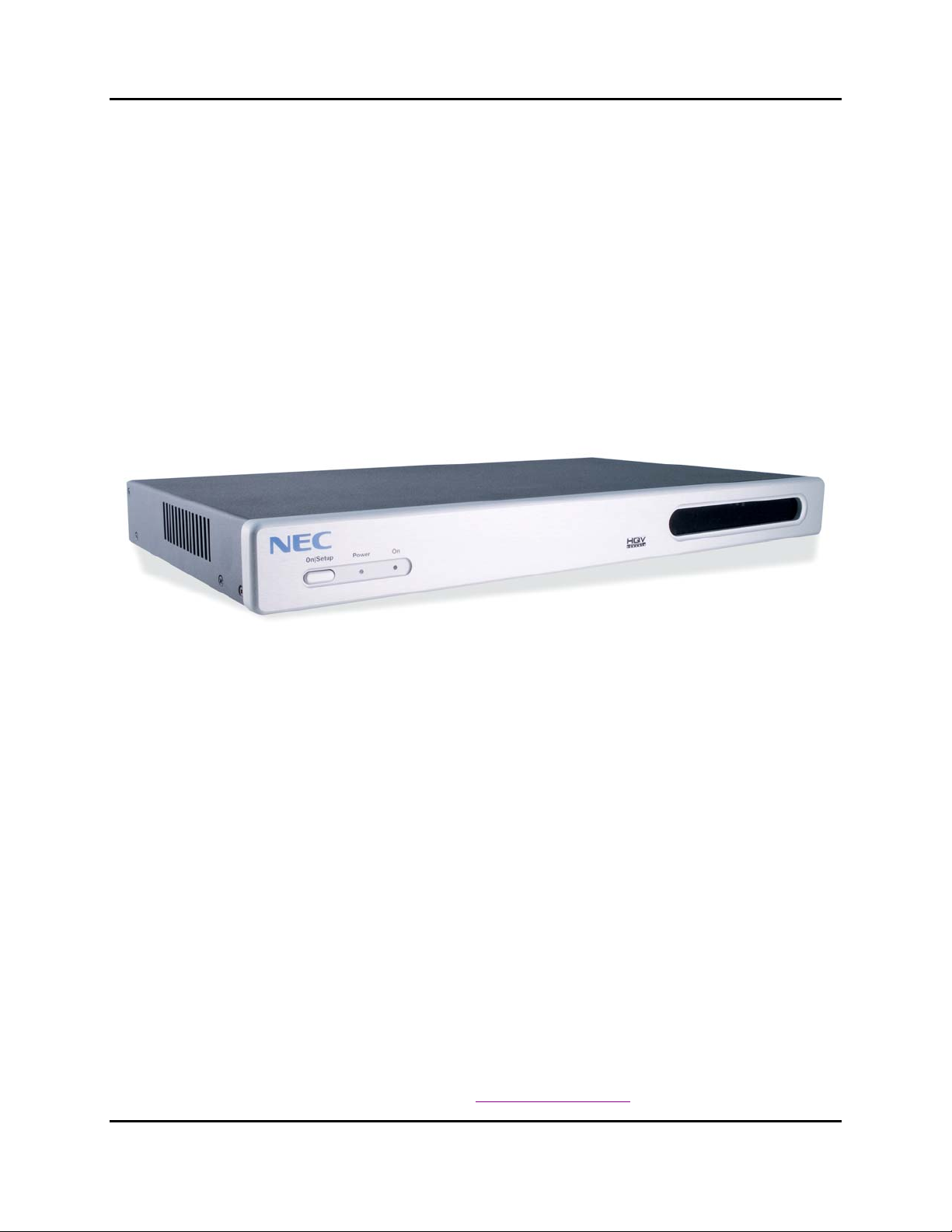
The NEC TheaterSync (see Figure 1) is a high performance video signal processor intended as a
companion for plasma and projector displays. TheaterSync brings the power of Silicon Optix
HQVTM (“Hollywood Quality Video”TM) technology to viewers of plasma and projector
displays. Initially conceived in the military research labs of Lockheed Martin and then refined
and commercialized by Teranex and Silicon Optix, HQV video processing has been the
technology of choice of film and video professionals in broadcast and studio environments for
years. A breakthrough in cost reduction and packaging now enables this revolutionary
technology - previously found only in Professional Post Production, Film Editing and Broadcast
Studios – to be delivered to your home or business viewing environment.
Figure 1: NEC TheaterSync Video Processor
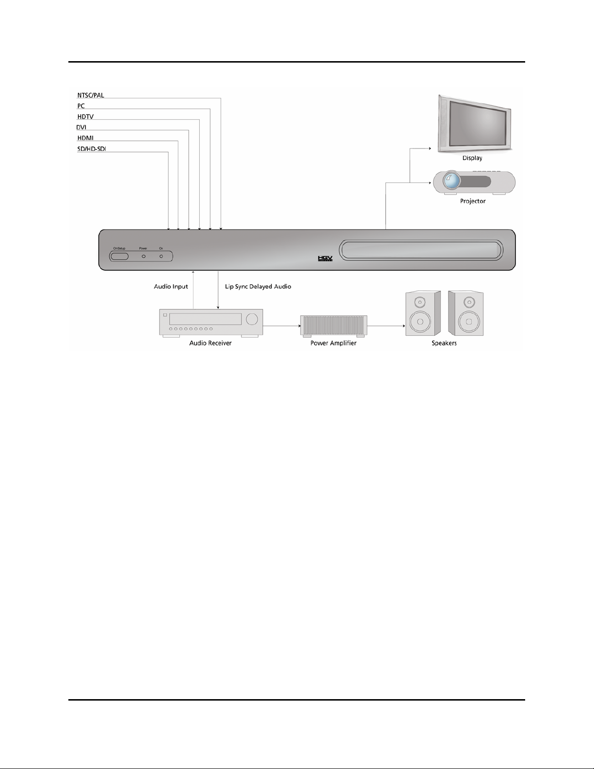
As a video signal processor, TheaterSync receives the video signals generated by a wide variety
of consumer electronic and professional devices, switches between them, and applies HQV
signal processing to the selected signal (see
appropriate resolution and aspect ratio of the plasma panel, projector, or other display device.
HQV signal processing includes the following powerful features:
• State-of-the-art, motion-adaptive de-interlacing for both SDTV and HDTV
• Temporal Recursive Noise Reduction
• Codec Noise Reduction (includes mosquito noise reduction and block artifact removal)
• Detail Enhancement
• Fully-automatic detection and correction for multiple film/video cadences (3:2, 2:2, vari-
speed, 6:4, 8:7, etc.)
• AnyPlace
• Brightness-Contrast Enhancement
• Color Space Conversion and Color Temperature Adjustment
For more information on HQV technology, visit http://www.hqv.com.
TM
technology for extreme off-axis keystone correction
Figure 2). The processed signal is then scaled to the
Page 10 NEC Solutions, Inc.
Page 11
TheaterSync Video Processor User Manual MKT-0026-UMN-1.002F
Figure 2: Typical TheaterSync Application
TheaterSync also performs a number of useful signal processing functions such as high-quality
video scaling, switching, extreme keystone correction and audio delay, thus eliminating the
requirement for stand-alone scalers or audio delay units within your system.
TheaterSync offers access to a truly wide range of signal inputs – everything from SDTV
(composite, S-Video and component) to HD-SDI and all popular video and computer graphics
signals in between (including analog RGB, DVI, and HDMI) may be selected as inputs.
TheaterSync provides video output in HDMI, DVI and analog RGB formats on dedicated
connectors.
All this functionality can be controlled through a simple 20-button IR remote control unit (see
Figure 5). Simple navigation keys bring access to a simple, yet elegant OSM (On-Screen
Menu). Video input device selection is accomplished using dedicated IR remote buttons.
Access to the HQV features is also provided through dedicated IR remote buttons. Also,
TheaterSync provides the professional user with flexible control methodologies of RS-232, USB
and Ethernet. For details on the control programming protocol, refer to the TheaterSync Service
Manual.
The TheaterSync video processor is available in a compact and attractive desktop package that
can be rapidly fitted to a standard 19” rack using a rack mounting kit (included).
NEC Solutions, Inc. Page 11
Page 12

MKT-0026-UMN-1.002F TheaterSync Video Processor User Manual
Features and Specifications
Input Video Signals
¾ Composite Video (NTSC, PAL and SECAM)
¾ S-Video (NTSC and PAL)
¾ Component (YPbPr for SDTV and HDTV in American and European formats)
¾ Analog RGB (VGA to SXGA60Hz)
¾ DVI (VGA to QXGA)
¾ HDMI
¾ SDI (including HD-SDI and audio)
Output Video Signals
¾ Analog RGB (VGA to UXGA)
¾ DVI (VGA to QXGA)
¾ HDMI
Input Audio Signals
¾ S/PDIF
¾ Toslink
¾ HDMI
Output Audio Signals
¾ S/PDIF
¾ Toslink
¾ HDMI
Video and Audio Processing Capability
¾ Scaling
¾ Extreme Keystone Correction (+/- 40o horizontal, +/- 30o vertical)
¾ Audio Delay
¾ Input Switching
¾ Aspect Ratio Correction
¾ HQV Video Processing …
• Temporal-Recursive Noise Reduction
• Codec Noise Reduction
• Fully-automatic cadence detection and correction
• Detail Enhancement
• Advanced motion-adaptive de-interlacing
Control
¾ IR Remote Control
¾ RS-232
¾ USB (for connection to Crestron / AMX boxes)
¾ Ethernet
Page 12 NEC Solutions, Inc.
Page 13

TheaterSync Video Processor User Manual MKT-0026-UMN-1.002F
Physical Characteristics
Dimensions: 17.0” x 9.7” x 1.75” (43.2 x 24.6 x 4.4 cm)
Weight : 7 lbs. (3.2 kg)
Power: 100-240V, 47-63 Hz, 72W
Panel Diagrams
Figure 3: TheaterSync Front Panel Drawing
Figure 4: TheaterSync Rear Panel Drawing
NEC Solutions, Inc. Page 13
Page 14

MKT-0026-UMN-1.002F TheaterSync Video Processor User Manual
3 Installation
3.1 List of Standard Components
The TheaterSync processor ships with a number of standard components. When unpacking your
unit, verify that the following items are included:
• TheaterSync unit (qty 1)
• IEC-320 American AC power cord (qty 1)
• Infrared remote control (qty 1)
• Rack-mount adapter kit (qty 1)
• TheaterSync User Manual (qty 1)
3.2 Setting up your TheaterSync
To set up your TheaterSync unit, follow the steps below:
1. Connect the TheaterSync unit to the video input sources.
2. Connect the TheaterSync unit to the display device.
NOTE: If you are connecting to a panel or projector that supports the coding of HDCP
encrypted material on its DVI input, you must connect to that DVI input using TheaterSync’s
HDMI OUT connector (and an HDMI to DVI adapter).
3. To power up the unit, press the Power switch located on the rear of the unit, close to the
power cord. The Power switch may be left on in normal operation. The On/Setup button
on the front panel may be used to put the unit into a low-power state (Setup Mode).
NOTE: When TheaterSync is in Setup (Stand-by) Mode, the output to the projector or panel is
temporarily suspended.
4. Select the output resolution to match the native resolution of the display device:
a) Place the unit in Setup (Stand-by) Mode by toggling the Operate/Setup button on the
IR remote (or by using the On/Setup button on the unit’s front panel).
b) Using the up/down arrow keys of the remote, cycle through the different setup modes
(which will be displayed on the box LCD display) until the output resolution mode is
selected (“OUT = xxx” will appear on the LCD display, where ‘xxx’ is the current
active output resolution)
c) Using the left/right arrow keys, select the desired output resolution.
5. Return TheaterSync to Operate Mode by pushing the On/Setup button on the front panel
or the Power button on the IR Remote. This activates the TheaterSync output circuits.
Further adjustments may be made using the TheaterSync OSM (On-Screen Menu).
Page 14 NEC Solutions, Inc.
Page 15

TheaterSync Video Processor User Manual MKT-0026-UMN-1.002F
For projection applications where keystone correction is required, continue with the following
steps:
6. If the projector has an AUTOSET or AUTODETECT feature, disable this function.
These projector modes may cause image distortion if a keystone-corrected image is
applied to the projector input.
7. Select the “Advanced” menu from the TheaterSync OSM, then select “Projection”, and
“Horizontal and Vertical Keystone” submenus.
8. Using the up/down arrow keys, select in turn each of the image corner sliders and then
use the left/right arrow keys to move the corner to the desired location on the screen.
Continue adjustments until the projected image matches the target screen geometry.
NEC Solutions, Inc. Page 15
Page 16

MKT-0026-UMN-1.002F TheaterSync Video Processor User Manual
4 TheaterSync User Interface
4.1 IR Remote Control
All TheaterSync user interface controls are accessed via infrared (IR) remote control. The
remote has three groups of controls:
a) OSM Navigation (including the Operate/Setup Key),
b) Video Source Selection, and
c) HQV Feature Selection.
You may also select video sources and HQV processing features through the
controls, however dedicated IR remote keys provide you with quick one-touch access to the most
frequently used commands.
Figure 5 illustrates the TheaterSync remote control.
OSM navigation
Figure 5: TheaterSync Remote Control
A description of the various buttons and their functions is as follows:
Page 16 NEC Solutions, Inc.
Page 17

TheaterSync Video Processor User Manual MKT-0026-UMN-1.002F
The Operate/Setup button toggles the TheaterSync between “Operate” and “Setup” modes of
operation (as described in the next section of this User Interface chapter).
The Menu button is used to invoke the OSM main menu.
The Up/Down/Left/Right Arrow buttons are used to navigate the
OSM.
The Enter/Select button is used to activate an OSM menu selection.
Direct (one-touch) input selection is possible using the buttons below:
• The RGB button selects the VGA port as the active input.
• The DVI button selects the DVI port as the active input.
• The Video button selects the composite video port as the active input.
• The S-Video button selects the S-Video port as the active input.
• The YPbPr button selects component video as the active input.
• The HDMI button selects HDMI as the active input.
• The SDI button selects the SDI port as the active input
Additional buttons are available to directly access key video processing features and to cycle
through the available enhancements:
• The BCE button activates/deactivates the Brightness / Contrast Enhancement feature
• The Aspect Ratio button cycles through and selects the available aspect ratio treatments
available for the current input and output mode combination (for description of aspect
ratio treatments, see section
5.2)
• The TRNR button accesses the Temporal Recursive Noise Reduction feature, cycling
through the four available settings (Off, Low, Medium, and High)
• The CNR button accesses the Codec Noise Reduction feature, cycling through the four
available settings (Off, Low, Medium, and High)
• The Film button cycles through the three available film mode treatments for active video
(Auto Film/Video mode detect, Force to Video mode, Force to Film mode)
• The Split button activates/deactivates a split-screen mode for direct comparison of the
image with and without noise reduction activated.
4.2 TheaterSync Operational Modes
TheaterSync has two operational modes, Operate and Setup. These modes are selected by a
dedicated key on the IR remote. TheaterSync also enables selection of the Operate Mode with
RS-232, USB, or Ethernet.
NEC Solutions, Inc. Page 17
Page 18

MKT-0026-UMN-1.002F TheaterSync Video Processor User Manual
4.2.1 Operate Mode
Operate Mode is entered by toggling the Operate/Setup button on the IR remote. A brief
transition of about 3 seconds occurs when Operate Mode is entered. During this transition
period, the 24 x 2 LCD Display indicates
THEATERSYNC
Please Wait
In Operate Mode, the video output signals are activated and you may control all of TheaterSync
parameters with the remote control (except for Setup restricted parameters, as noted below).
The LCD front panel display indicates the following information in its 24 x 2 character matrix:
(Selected Input Connector) = (Input Signal Detected)
Output = (Output Resolution currently selected)
Depending on which IR remote key that you select, the operation of the OSM is slightly
different.
If you select the Menu key, the TheaterSync OSM appears on the screen. Complete details on
the OSM may be found in chapter 5. The OSM remains on the screen until you press the Menu
key once again or until 30 seconds with no IR remote activity passes.
If you select one of the dedicated HQV Feature keys, the HQV feature is immediately activated.
A brief message indicating the status of the selected HQV feature appears momentarily on the
screen (e. g. TRNR = Medium or CNR = Off).
If you select one of the Input Source keys, the selected source is chosen as the input. The
previously selected HQV Features, Aspect Ratio Treatment, Scaling and Video Parameters are
all preserved for each input; each input will appear exactly as you left it.
TheaterSync powers up in Operate mode. All operational parameters are retained from the
previous session. A Factory Reset returns all parameters to the default state (defaults are
described in chapter 5), except for the input signal. The input signal most recently used is
retained as the power-up input signal.
4.2.2 Setup (Stand-by) Mode
Setup mode is entered by toggling the Operate/Setup button on the IR remote.
In Setup mode TheaterSync is in a low-power state. The output signals are de-activated (no
output will appear on your display device). Setup mode enables you to power the unit down, but
still leaves the IR receiver circuitry energized so that you can re-start the system with the IR
remote. When the unit is in Setup Mode, you can also make adjustments to certain sensitive
Page 18 NEC Solutions, Inc.
Page 19

TheaterSync Video Processor User Manual MKT-0026-UMN-1.002F
parameters, such as Output Resolution. Visual feedback for the adjustments of Setup Mode is
seen on the 24 x 2 LCD display, rather than on OSM of the main screen. Sensitive parameters
are placed in the Setup Menu so that an inadvertent key stroke with the IR remote does not cause
a change in a parameter that would be difficult to recover from. Table 1 lists the Setup
parameters and
Table 2 lists the output resolutions currently supported in the unit.
Table 1: Setup Parameters
Parameter Description
OUT = XXX ## Hz
LCD Brightness = On (Off)
Output Sync = Free Run (Vadjust 1:1,
Vjam)
BAUD = #####
OSM Location = Input (Output)
Cycles through all of the available TheaterSync output
modes (see
Turns On (Off) the 24 x 2 LCD Display during Operate
Mode
These settings enables to adjust the output sync:
Free Run – Establishes a precise output timeline
Vadjust 1:1 – Forces the output timeline to be frame
locked to the input by inserting or deleting entire lines of
output video
Vjam – Maintains frame lock by truncating final line of
output frame
Lets you choose a baud rate of 1200, 9600, 19200,
57600, or 115000.
The OSM may be located pre (Input side) or post (Output
side) scaling and keystone correction
1
Table 2 for a list of Output Resolutions).
PC Control = Active (Inactive)
DHCP = On (Off)
IP=aaa.bbb.ccc.ddd Select IP Address (selectable only if DHCP = Off)
DNS=aaa.bbb.ccc.ddd Select DNS Address (selectable only if DHCP = Off)
2nd DNS=aaa.bbb.ccc.ddd
Gateway=aaa.bbb.ccc.ddd Select Gateway Address (selectable only if DHCP = Off)
SubMask=aaa.bbb.ccc.ddd Select SubNet Mask (selectable only if DHCP = Off)
Serial No = ###### Indicates the Serial # of TheaterSync unit
MAC = ## ## ## ## ## ## Indicates the MAC Address of TheaterSync unit
Turns On (Off) the computer control capability
Turns on Dynamic IP Address Selection
Select Alternate DNS Address
(selectable only if DHCP = Off)
1
The default parameters configurations are highlighted in bold.
NEC Solutions, Inc. Page 19
Page 20

MKT-0026-UMN-1.002F TheaterSync Video Processor User Manual
Table 2: TheaterSync Output Modes
Output Mode Comments
VGA 60 Hz (640 x 480)
VGA 50 Hz (640 x 480)
848 x 480 60 Hz
SVGA 60 Hz (800 x 600)
SVGA 50 Hz (800 x 600)
720p 60 Hz (1280 x 720)
720p 50 Hz (1280 x 720)
XGA 72 Hz (1024 x 768) VESA Standard
XGA 60 Hz (1024 x 768) VESA Standard
XGA 50 Hz (1024 x 768)
1360 x 768 60 Hz
1365 x 768 60 Hz
1400 x 788 60 Hz
SXGA 60 Hz (1280 x 1024)
SXGA 50 Hz (1280 x 1024)
SXGA+ 60 Hz (1400 x 1050)
SXGA+ 50 Hz (1400 x 1050)
1080p 60 Hz (1920 x 1080)
1080p 50 Hz (1920 x 1080)
1080p 48 Hz (1920 x 1080)
QXGA 60 Hz (2048 x 1536)
QXGA 50 Hz (2048 x 1536)
QXGA 48 Hz (2048 x 1536)
VESA Standard
VESA Standard
/
VESA Standard
VESA Standard
SMPTE Standard
SMPTE Standard
VESA Standard
/
/
/
VESA Standard
VESA Standard
VESA Standard
VESA Standard
SMPTE Standard
SMPTE Standard
SMPTE Standard
/
/
/
On entry to setup mode, the 24 x 2 LCD display indicates the following:
THEATERSYNC
Setup
Select the Menu key on your IR Remote to bring up the Setup Menu on the 24 x 2 LCD display.
The LCD display will indicate the following:
“Parameter” = ???
Setup Mode
Using the Up and Down navigation keys on the remote, you can select the next parameter in a
circular list of parameters. Using the Left and Right navigation keys on the remote, you can
select the value of the parameter. In some cases, the parameter is visible in the setup menu, but
may not be altered (such as Serial Number or MAC Address).
Selection of IP addresses is slightly different. IP addresses may only be selected if the DHCP
parameter has been set to “Off”. In this case, you use the Left or Right navigation key to “enter”
the IP address. The Left key will highlight the rightmost octet; the Right key will select the
Page 20 NEC Solutions, Inc.
Page 21

TheaterSync Video Processor User Manual MKT-0026-UMN-1.002F
leftmost octet. The Up/Down keys may then be used to increase/decrease the value of the octet.
Subsequent presses of the Left/Right key will highlight the octet immediately to the left/right.
The Up/Down keys may then be used to increase/decrease the value of the octet. When the
leftmost/rightmost octet is selected, an additional Left/Right key selection will “exit” the IP
address. The Up/Down arrows may then be used to select the next parameter. Table 1 lists the
Setup parameters.
NEC Solutions, Inc. Page 21
Page 22

MKT-0026-UMN-1.002F TheaterSync Video Processor User Manual
5 On-Screen Menu
5.1 OSM Menu Structure
The On-Screen Menu (OSM) is the primary way of controlling and selecting functions in the
TheaterSync system. When first powered up, the TheaterSync will be in a Factory Default
configuration, with English as the OSM language, Component Video as Video Input, and
S/PDIF Audio as Audio input. All other Factory Default parameters are indicated in Table 4.
When the user selects the Factory Reset from the OSM menu, TheaterSync reloads all of these
default parameters, replacing any adjustments previously made. Certain parameters are not
affected by the Factory Reset and are left in their most recently selected position. These
parameters are: Language, Selected Input, and Selected Audio Input. As indicated in chapter
the Setup Parameters are not affected by Factory Reset.
TheaterSync remembers all the signal processing parameters on a selected input basis. When the
user powers down or selects a different input, the processing parameters previously selected are
automatically re-established when returning to that input. An Input Reset sets the currently
selected input to its default parameters. (This allows the user to reset a specific input channel
without disturbing selections that affect the entire TheaterSync operation).
4,
A complete view of the OSM menu structure is shown in
Table 3: OSM Main Menu Structure
Icon
ON OFF
Descriptio
n
Inputs Enter this submenu to select the video or audio input.
Enter this menu to adjust the image brightness, contrast,
Picture
Setup
Language Enter this submenu to select the language used by the OSM.
Info
sharpness, gamma correction, black level, color temperature,
color, hue, tint, and aspect ratio.
Enter this submenu to review the video system, select the
background color, reset to default settings, and setup the menu
position.
Enter this submenu to view information about the system (input
resolution, horizontal and vertical frequency, output resolution,
horizontal and vertical frequency, firmware revision, FPGA
revision, serial number, and IP address).
Table 3 and Table 4.
Functionality
Page 22 NEC Solutions, Inc.
Page 23

TheaterSync Video Processor User Manual MKT-0026-UMN-1.002F
Icon
ON OFF
Descriptio
n
Advanced Enter this submenu to access the advanced menu options.
Table 4: OSM Complete Menu Structure
OSM Menu Level
Level 1 Level 2 Level 3 Level 4 Level 5
Component - - HDTV or SDTV
VGA - - SDTV, HDTV, or Graphics
DVI - - Graphics, RGB HDTV
Video
Audio
Inputs
Audio
Delay
S-Video - - SDTV
Composite - - SDTV
SDI - - SDI input selection
HDMI - - HDMI input selection
TosLink - -
S/PDIF - -
-100 - +100,
0 (default)
- -
Functionality
Comments
Selects TosLink as audio
source
Selects S/PDIF as audio
source
Adjusts the Audio Delay
through TheaterSync. The
Audio Delay is calibrated in
milliseconds. A delay of ‘0’
selects a delay that is
automatically adjusted to the
number of frames of delay
introduced by TheaterSync
processing. The Audio Delay
adjustment allows the user to
compensate for Audio or Video
delay that is introduced by
other system components
The higher the setting, the
Brightness
Picture
NEC Solutions, Inc. Page 23
Picture
Settings
Contrast
0 - 100,
50 (default)
0 - 100,
50 (default)
-
-
greater the brightness.
The lower the setting, the lower
the brightness.
The higher the setting, the
greater the contrast.
The lower the setting, the lower
the contrast.
Page 24

MKT-0026-UMN-1.002F TheaterSync Video Processor User Manual
OSM Menu Level
Level 1 Level 2 Level 3 Level 4 Level 5
Sharpness
Detail
Enhancement
0 - 100,
50 (default)
0 - 100,
50 (default)
-
-
Gamma 1.0
(default)
Gamma 1.5
Gamma 2.2
Input
Gamma
Gamma 2.4
Gamma 2.5
Comments
The higher the setting, the
sharper the image (edge
enhancement).
The lower the setting, the lower
the sharpness.
The higher the setting, the
better the image (detail
enhancement).
The lower the setting, the lower
the detail enhancement.
Gamma LUT for linear
response (1.0).
Gamma LUT for non-linear
response (1.5).
Gamma LUT for non-linear
response (2.2).
Gamma LUT for non-linear
response (2.4).
Gamma LUT for non-linear
response (2.5).
Picture
Picture
Settings
Gamma
Mode
Color Temp
Color
Gamma 2.8
Gamma 1.0
(default)
Gamma 2.2
Output
Gamma 2.4
Gamma
Gamma 2.5
Gamma 2.8
9300K 6500K
(default)
-
5500K -
0 - 100,
50 (default)
-
Gamma LUT for non-linear
response (2.8).
Gamma LUT for linear
response (1.0).
Gamma LUT for non-linear
response (2.2).
Gamma LUT for non-linear
response (2.4).
Gamma LUT for non-linear
response (2.5).
Gamma LUT for non-linear
response (2.8).
Gives a blue tint to the white
colors.
Gives a neutral tint to the white
colors.
Gives a red tint to the white
colors.
The higher the setting, the
greater the intensity. The lower
the setting, the lower the
intensity.
Page 24 NEC Solutions, Inc.
Page 25

TheaterSync Video Processor User Manual MKT-0026-UMN-1.002F
OSM Menu Level
Level 1 Level 2 Level 3 Level 4 Level 5
0 - 360,
Picture
Picture
Settings
Aspect
Ratio
Hue
Input Reset
Standard
(default)
Full Screen - -
Zoom - -
180
(default)
Confirm
YES/NO
- -
-
-
Comments
The higher the setting, the
more greenish the picture. The
lower the setting, the more
purplish the picture.
Returns all of the adjustments
for a single input to the Factory
Default state. All the other
inputs and selections that affect
the TheaterSync operation
(such as Keystone Correction)
are unaffected
Maintains the aspect ratio:
• 4:3 input and 16:9 output -
Output image would be
displayed with black pillar
bars (maintains input
aspect ratio)
• 4:3 input and 4:3 output -
No change
• 16:9 input and 16:9 output -
No change
• 16:9 input and 4:3 output -
Output image would be
displayed with black letter
box bars (maintains input
aspect ratio)
Fills the Output Screen by
stretching the image (distorting
the aspect ratio):
• 4:3 input and 4:3 output –
Grayed out, no action
• 4:3 input and 16:9 output –
Image is linearly stretched
horizontally to fill the output
screen
• 16:9 input and 4:3 output -
Image is linearly stretched
vertically to fill the output
screen
• 16:9 input and 16:9 output
– Grayed out, no action
See section
information.
Fills the Output Screen by
cropping the image
(maintaining aspect ratio).
• 4:3 input and 4:3 output –
Grayed out, no action
• 4:3 input and 16:9 output –
Top and bottom portions of
the image are cropped
5.2 for more
NEC Solutions, Inc. Page 25
Page 26

MKT-0026-UMN-1.002F TheaterSync Video Processor User Manual
OSM Menu Level
Level 1 Level 2 Level 3 Level 4 Level 5
Picture
Anamorphic - -
Aspect
Ratio
Stadium - -
Vertical 0 - 100 -
Picture
Position
Horizontal 0 - 400 -
Autosync - - -
0 - 200,
Sync
Clock
100
- Adjusts clock sync
(default)
Comments
• 16:9 input and 4:3 output –
Left and right portions of
the image are cropped
• 16:9 input and 16:9 output
– Grayed out, no action
See section
5.2 for more
information.
This mode is used with DVDs
(Standard Definition) that are in
Widescreen [16:9] format:
• 4:3 input and 4:3 output –
The image is letter boxed
• 4:3 input and 16:9 output –
The image appears full
screen
• 16:9 input and 4:3 output –
Grayed out, no action
• 16:9 input and 16:9 output
– Grayed out, no action
See section
5.2 for more
information.
Fills the Output Screen by
stretching the image (distorting
the aspect ratio):
• 4:3 input and 4:3 output –
Grayed out, no action
• 4:3 input and 16:9 output –
Image is non-linearly
stretched horizontally to fill
the output screen
• 16:9 input and 4:3 output –
Grayed out, no action
• 16:9 input and 16:9 output
– Grayed out, no action
See section
5.2 for more
information.
Adjusts the vertical position of
image (default setting depends
on the input video/graphics
source)
Adjusts the horizontal position
of image (default setting
depends on the input
video/graphics source)
Automatically centers the
image for graphic inputs
Page 26 NEC Solutions, Inc.
Page 27

TheaterSync Video Processor User Manual MKT-0026-UMN-1.002F
OSM Menu Level
Level 1 Level 2 Level 3 Level 4 Level 5
Picture Overscan
Phase
Status
Left
Right
Top
Bottom
0 - 100,
50 (default)
- Adjusts clock phase
Off - On - -
0.0 – 10.0
0.0 (default)
0.0 – 10.0
0.0 (default)
0.0 – 10.0
0.0 (default)
0.0 – 10.0
0.0 (default)
-
-
-
-
Center - -
Top Left - -
Menu
Top Right - -
Position
Bottom Left - -
Bottom Right - -
Setup
Test
Patterns
12 V
Triggers
Factory
Reset
- - -
Trigger A
Trigger B
Confirm
YES/NO
Off (default)
On - -
Off (default)
On - -
- - Resets to default settings
- -
- -
Comments
Sets the percentage of
Overscan on the left edge
Sets the percentage of
Overscan on the right edge
Sets the percentage of
Overscan on the top edge
Sets the percentage of
Overscan on the bottom edge
Sets the OSM menu position in
the center of the display
Sets the OSM menu position in
the top left corner of the display
Sets the OSM menu position in
the top right corner of the
display
Sets the OSM menu position in
the bottom left corner of the
display
Sets the OSM menu position in
the bottom right corner of the
display
Displays test pattern images on
screen, with OSM off. Up- and
down-arrows navigate user
through all 10 available test
patterns. Left-arrow key
returns user to Test Pattern
menu.
Language
English - - -
Selects the language for the
OSM menus
French - - -
German - - -
Italian - - -
Spanish - - -
NEC Solutions, Inc. Page 27
Page 28

MKT-0026-UMN-1.002F TheaterSync Video Processor User Manual
OSM Menu Level
Level 1 Level 2 Level 3 Level 4 Level 5
Portuguese - - -
Swedish - - -
Russian - - -
Japanese - - -
Language
Chinese
Simplified
Chinese
Traditional
- - -
- - -
Korean - - -
Input
Resolution
Input H
Frequency
Input V
Frequency
Output
Mode
Output
Resolution
Output H
Frequency
Output V
Frequency
- - - Shows the source resolution
- - - Shows the source H frequency
- - - Shows the source V frequency
- - - Shows the display mode
- - - Shows the display resolution
- - - Shows the display H frequency
- - - Shows the display V frequency
Comments
Selects the language for the
OSM menus
Info
Sync - - - Shows the synchronization type
Firmware
Revision
Serial
Number
- - -
- - -
Shows the firmware revision
number
Shows the board serial
number.
Shows the IP address only if
IP Address - - -
the Ethernet cable is connected
to the board and the IP address
has been assigned by DHCP
FPGA
Revision
Standby
Micro
Rev. #
Advanced Projection
- - -
- - -
Horizontal
and Vertical
Top Left H -
Keystone
Top Left V -
Shows the current revision
number for the FPGA code
Shows the firmware revision
number for the standby-mode
microcontroller
Controls the horizontal position
of the display top left corner
Controls the vertical position of
the video display top left corner
Page 28 NEC Solutions, Inc.
Page 29

TheaterSync Video Processor User Manual MKT-0026-UMN-1.002F
OSM Menu Level
Level 1 Level 2 Level 3 Level 4 Level 5
Advanced
Bottom Left
H
Bottom Left
V
-
-
Top Right H -
Horizontal
and Vertical
Top Right V -
Keystone
Projection
Bottom
Right H
Bottom
Right V
-
-
Front
Tabletop
- Normal projection mode
(default)
Projection
Mounting
Front
Ceiling
Rear
Tabletop
-
-
Rear Ceiling -
Comments
Controls the horizontal position
of the video display bottom left
corner
Controls the vertical position of
the video display bottom left
corner
Controls the horizontal position
of the display top right corner
Controls the vertical position of
the display top right corner
Controls the horizontal position
of the video display bottom
right corner
Controls the vertical position of
the video display bottom right
corner
Compensate the image for
ceiling-mounting scenario
Compensate the image for
projection from behind the
screen
Compensate the image for
ceiling-mounted rear-projection
scenario
Video
Processing
Mode
HQV Film
Mode
BCE
HQV On
(default)
HQV Off
(Bypass)
Auto
(default)
Video - -
Film - -
2
Video
- - Process main image in the TVP
Process main image in Overlay
- -
Scaler (bypass the TVP
processor)
The system automatically
- -
selects the best mode for deinterlacing (film or video)
Forces to video mode for deinterlacing
Forces to film mode for deinterlacing
Expands video range signals
- -
(16-235) linearly to full range
output
Provides Luma processing
Cinema - -
optimized for movies; expands
video range signals.
2
Default for HDMI, Component, Composite, S-Video, and SDI inputs.
NEC Solutions, Inc. Page 29
Page 30

MKT-0026-UMN-1.002F TheaterSync Video Processor User Manual
OSM Menu Level
Level 1 Level 2 Level 3 Level 4 Level 5
BCE
Advanced
HQV Noise
Reduction
Vivid - -
Dark Scene - -
Bright Scene - -
Graphics
TRNR
CNR
3
- -
Off -
Low
(default)
Med -
High -
Off (default)
Low -
Medium -
- Select TRNR -- low bias setting
-
Comments
Enhances color, expands video
range signals.
Enhances detail in dark
scenes, expands video range
signals.
Enhances detail in bright
scenes, expands video range
signals.
Transfers full range input
signals (0-255) to full range
output
Turns off Temporal Recursive
Noise Reduction (TRNR)
Select TRNR -- medium bias
setting
Select TRNR -- high bias
setting
Turns off the Codec Noise
Reduction
Select Codec Noise Reduction,
low level
Select Codec Noise Reduction,
medium level
Select Codec Noise Reduction,
high level
Split
High -
Off (default)
On - - Toggles the split screen mode
- - Toggles the split screen mode
5.2 Aspect Ratio
TheaterSync provides five different aspect ratio treatments. The operation mode of these
treatments depends on the aspect ratio of the input channel and the output display.
The TheaterSync assumes that the aspect ratio of input and output is consistent with the industry
standard definition of the aspect ratio of the particular input signal and video mode. Output
aspect ratio is thus determined by the resolution selected by the user in Setup Mode. Input aspect
ratio is determined by the TheaterSync video mode recognition circuitry. Only two output aspect
ratios are supported, 4:3 and 16:9
3
Default for DVI and Analog RGB inputs.
4
The special case of 1280 x 1024 SXGA (an aspect ratio of 5:4) on output is treated as if it were 4:3. The output of
a 1280 x 1024 display will be slightly distorted; circles will appear to be vertically oriented ovals. Since the
Page 30 NEC Solutions, Inc.
4
.
Page 31

TheaterSync Video Processor User Manual MKT-0026-UMN-1.002F
Inputs considered to have 4:3 aspect ratio are:
• Computer Graphics signals with a 4:3 aspect ratio appearing on the DVI and Analog
RGB inputs
• SDTV signals (NTSC and PAL derived) appearing on the Composite, S-Video, and
Component inputs
• SDTV signals (NTSC and PAL derived) appearing on the SDI input
• SDTV signals (NTSC and PAL derived) appearing on the HDMI input
Inputs considered to have 16:9 aspect ratio are:
• Computer Graphics signals with a 16:9 aspect ratio appearing on the DVI and Analog
RGB inputs
• HDTV signals (480p, 720p, 1080i, 1080p) appearing on the Component input
• HDTV signals (480p, 720p, 1080i, 1080p) appearing on the SDI input
• HDTV signals (480p, 720p, 1080i, 1080p) appearing on the HDMI input
The five aspect ratio treatments, Standard, Full Screen, Zoom, Anamorphic, and Stadium are
intended to achieve different aspect ratio objectives, and therefore behave differently depending
on which input and output aspect ratios are currently selected. The Aspect Ratio objectives are
the following:
• Standard: always displays the correct aspect ratio of the input picture; adds black bars at
the top and bottom or sides of the picture to achieve this objective
• Full Screen: always fills the screen with the complete picture; linearly distorts the picture
to achieve this objective
• Zoom: always fills the screen with the correct aspect ratio of the input picture; crops the
picture’s top and bottom or sides to achieve this objective
• Anamorphic: intended to handle the specific case of 16:9 aspect ratio anamorphically
encoded into a 4:3 aspect ratio signal (e. g. an NTSC DVD encoded with a 16:9 picture
• Stadium: intended to handle the specific case of a 4:3 input aspect ratio and 16:9 output
aspect ratio
Table 5 to Table 8 present the five aspect ratio treatments over the four different combinations
of Input Aspect Ratio and Output Aspect Ratio.
TheaterSync is intended for Widescreen processing, the 1280 x 1024 SXGA is not a frequently encountered case.
Input of 1280 x 1024 will be treated as a pillar boxed 4:3 signal (i.e. it will have narrow black bars on the Right and
Left); aspect ratio of the picture content will be undistorted.
NEC Solutions, Inc. Page 31
Page 32

MKT-0026-UMN-1.002F TheaterSync Video Processor User Manual
Table 5: Aspect Ratio Treatments for 4:3 Input with 4:3 Output
OSM Menu Name Description
4:3 input signals shown full screen on 4:3 output display
Standard
Full Screen Grayed out. No action.
Zoom Same as “Standard” mode above.
Anamorphic or widescreen encoded DVDs shown letterbox on
4:3 output display. These DVDs have 16:9 content that has
been compressed and expanded vertically to fit the NTSC or
PAL signal.
Anamorphic
Stadium Grayed out. No action.
Table 6: Aspect Ratio Treatments for 4:3 Input with 16:9 Output
OSM Menu Name Description
4:3 input signals are shown in a pillar box on the 16:9 output
display
Standard
Full Screen
4:3 input is linearly stretched horizontally to fill the 16:9 screen
Page 32 NEC Solutions, Inc.
Page 33

TheaterSync Video Processor User Manual MKT-0026-UMN-1.002F
OSM Menu Name Description
Zoom Grayed out. No action.
SDTV input is displayed on a full screen 16:9 output display
Anamorphic
4:3 input signals are non-linearly stretched in the horizontal
direction to fill 16:9 output displays. Horizontal and vertical
scaling is equal in the middle, more horizontal stretching
towards left and right sides to fill 16:9 outputs
Stadium
NEC Solutions, Inc. Page 33
Page 34

MKT-0026-UMN-1.002F TheaterSync Video Processor User Manual
Table 7: Aspect Ratio Treatments for 16:9 Input with 4:3 Output
OSM Menu Name Description
All HDTV inputs are assumed to be 16:9. HDTV input signals
(1080i and 720p) are shown in a letterbox on the 4:3 output
display
Standard
Image stretched vertically to fill full screen.
Full Screen
16:9 HDTV input signals shown in 4:3 output display, cropped
on left and right sides
Zoom
Anamorphic Grayed out. No action.
Stadium Grayed out. No action.
Page 34 NEC Solutions, Inc.
Page 35

TheaterSync Video Processor User Manual MKT-0026-UMN-1.002F
Table 8: Aspect Ratio Treatments for 16:9 Input with 16:9 Output
OSM Menu Name Description
16:9 input signals shown full screen on 16:9 output display
Standard
Full Screen Grayed out. No action.
Zoom Grayed out. No action.
Anamorphic Grayed out. No action.
Stadium Grayed out. No action.
NEC Solutions, Inc. Page 35
Page 36

MKT-0026-UMN-1.002F TheaterSync Video Processor User Manual
6 Appendix A
Table 9: Input Modes Supported
Input Timing Format
Item
No.
1 480i (NTSC) 720 x 485 60 Hz - - YES YES YES YES YES
2 576i (PAL) 720 x 576 50 HZ - - - YES YES YES YES
3
4 480p 720 x 483 60 Hz - YES YES - - YES -
5 576p 720 x 576 50 Hz - YES YES - - YES -
6
7
8
Mode
Description
576i
(SECAM)
HDTV 720
Progressive
HDTV 720
50 Hz
Progressive
HDTV 1080
Interlaced at
60 Hz
Resolution Frequency RGB DVI HDMI Composite S-video Component SDI
720 x 576
1280 x 720 60 Hz - YES YES - - YES YES
1280 x 720 50 Hz - YES YES - - YES -
1920 x 1080 60 Hz - YES YES - - YES YES
50 Hz - - - YES YES - -
Input Video Source
HDTV 1080
9
10
11
12
13
14
15
16 DOS TEXT 640 x 400 70 Hz YES YES YES - - - -
Interlaced at
50 Hz
1080p at
24 Hz
1080p at
25 Hz
1080p at
30 Hz
1080p at
24sF
1080p at
25sF
1080p at
30sF
1920 x 1080 50 Hz - YES YES - - YES YES
1920 x 1080 24 Hz - - - - - - YES
1920 x 1080 25 Hz - - - - - - YES
1920 x 1080 30 Hz - - - - - - YES
1920 x 1080 48 Hz - - - - - - YES
1920 x 1080 50 Hz - - - - - - YES
1920 x 1080 60 Hz - - - - - - YES
Page 36 NEC Solutions, Inc.
Page 37

TheaterSync Video Processor User Manual MKT-0026-UMN-1.002F
Input Timing Format
Item
No.
17
18
19 848 x 480 848 x 840 60 Hz YES YES - - - - -
20 1024 x 576 1024 x 576 60 Hz YES YES - - - - -
21
22
23 1360 x 768 1360 x 768 60 Hz YES YES - - - - -
24 1365 x 768 1365 x 768 60 Hz YES YES - - - - -
25 SXGA+ 1400 x 1050 60 Hz YES YES - - - - -
Mode
Description
VGA at
60 Hz
SVGA at
75 Hz
XGA at
75 Hz
SXGA at
75 Hz
Resolution Frequency RGB DVI HDMI Composite S-video Component SDI
640 x 480 60 Hz YES YES YES - - - -
800 x 600 75 Hz YES YES YES - - - -
1024 x 768 75 Hz YES YES YES - - - -
1280 x 1024 76 Hz YES YES YES - - - -
Input Video Source
26 UXGA 1600 x 1200 60 Hz - YES YES - - - -
27 WUXGA 1920 x 1200 60 Hz - YES - - - - -
28 QXGA 2048 x 1536 60 Hz - YES - - - - -
29
30
31
32
33 MAC 1440 x 960 96 Hz - YES - - - - -
34 MAC 20 1680 x 1050 88 Hz - YES - - - - -
35 MAC 23 1920 x 1200 76 Hz - YES - - - - -
MAC II
Normal 13in
MAC II
Normal 16in
MAC II
Normal 19in
MAC II
Normal 21in
640 x 480 67 Hz YES YES YES - - - -
832 x 624 75 Hz YES YES - - - - -
1024 x 768 75 Hz YES YES - - - - -
1152 x 870 75 Hz YES YES YES - - - -
NEC Solutions, Inc. Page 37
Page 38

MKT-0026-UMN-1.002F TheaterSync Video Processor User Manual
Page 38 NEC Solutions, Inc.
 Loading...