How it Works
Log In / Sign Up
Buy Points
How it Works
FAQ
Contact Us
Questions and Suggestions
Users
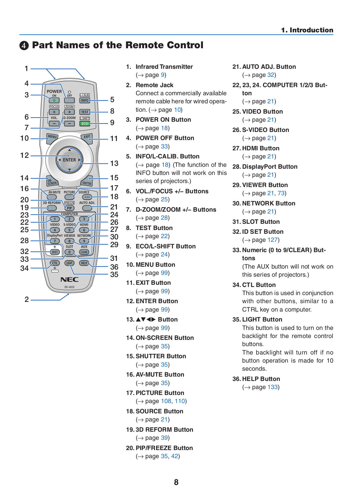
NEC
Loading...
P
PX1004UL
4
PX1004UL-B-18
2
PX1004UL-BK
2
PX1004UL black (NP18ZL)
PX1004UL-W-18
2
PX1004UL-WH
2
PX1005QL
6
PX1005QL-B-18
PX1005QL-W
PX1005QL-W-18
2
PX1005QL white
PX2000UL
4
PX2000UL-47ZL
2
PX2201UL
2
PX42M3
PX42M4A
PX42MP2A
PX42XM4A
5
PX602UL
4
PX602UL-B-35
2
PX602UL-BK
2
PX602UL-W-35
2
PX602UL-WH
2
PX602WL
3
PX602WL-B-36
2
PX602WL-BK
2
PX602WL-W-36
PX602WL-WH
2
PX602WL /WH/BK
PX-61XM3
3
PX-61XM3A
3
PX-61XM3G
PX-61XM4
2
PX-61XM4A
4
PX-61XM4G
PX-61XM4W
PX-61XR3
2
PX-61XR3A
3
PX-61XR3G
PX-61XR4
2
PX-61XR4A
5
PX700W
9
PX700W2
3
PX700W2-08ZL
PX700WG2
PX750CM
PX750U
10
PX750U-18ZL
2
PX750U2
3
PX750U2-18ZL
PX750UG2
PX800X
10
PX800X-08ZL
PX800X2
3
PX800X2-08ZL
PX800XG2
PX803UL
5
PX803UL-B-18
PX803UL-BK
PX803UL black
PX803UL black (NP18ZL)
PX803UL-W-18
PX803UL-WH
2
PX803UL white (NP18ZL)
PX-84VM5A
2
PX-84VP4
PX-84VP4DA
PX-84VP5A
PX-SP2U
PXT-32XD3
PXT-42S11S
PXT-42SPKR
PXT-42XD2
PX-TUAN-01
PX-TUAN-01 1005
PX-TUDI-01
Q
QB-MINI2
QIG-TMX-55UN
Quadro K2200
Quadro K4200
Quadro K5200
QuSL1100
QX-S5500
QX-S5500G
QX-S5524GP-4X1C
QX-S5524GT-4X1C
QX-S5524GT-4X2Q
QX-S5526P
QX-S5526P-D
QX-S5526T
QX-S5548GT-4X1C
QX-S5548GT-4X2Q
QX-S5550P
QX-S6632QP
QX-S6648XP-6Q
QX-S6648XT-6Q
R
R07F102A
R1000
R110d-1E
R 37 Xtra
Loading...
Loading...
Nothing found
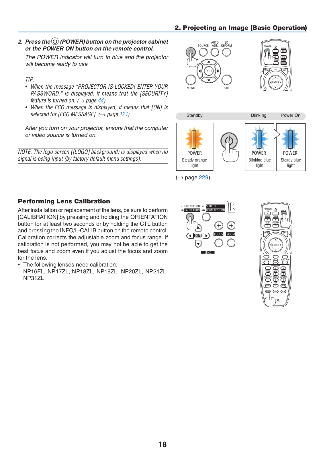
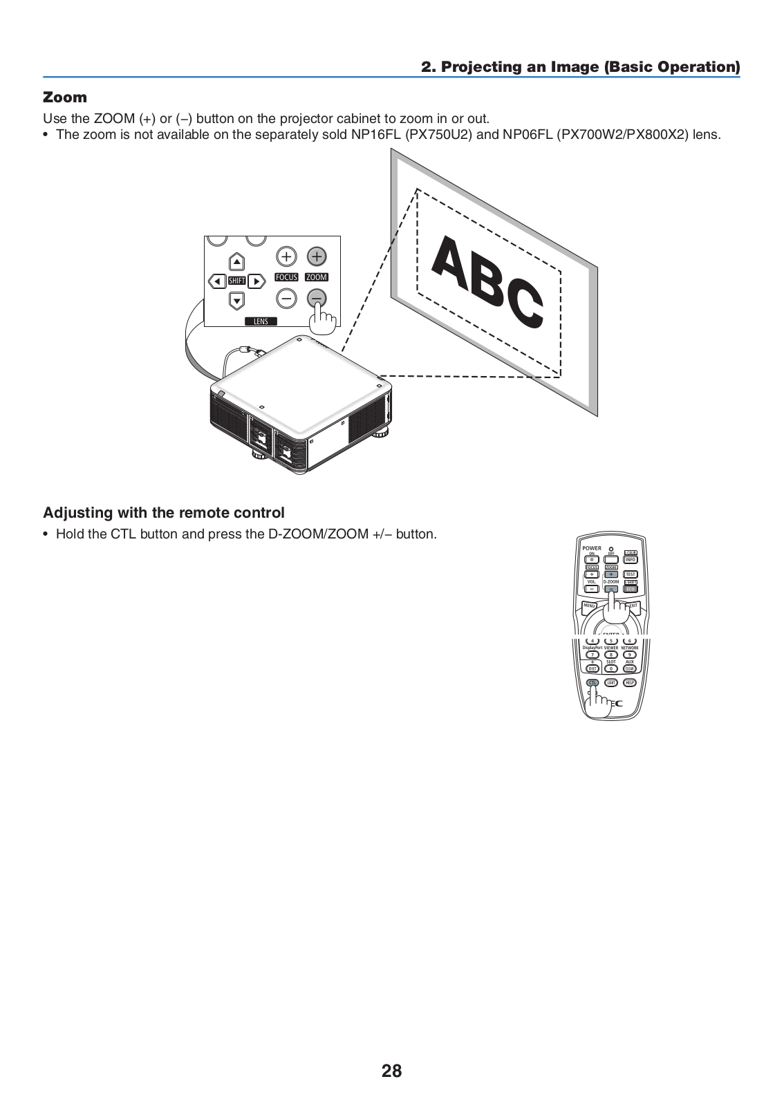
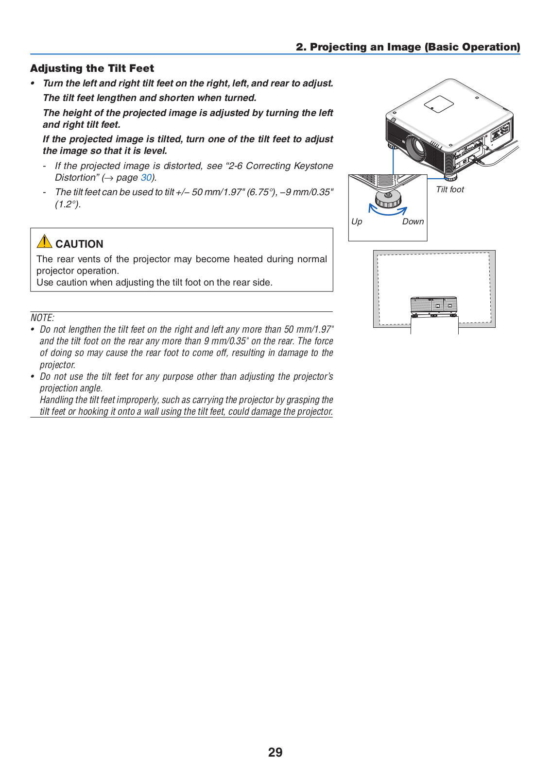
PX700W2
Installation Manual
5 pgs
3.46 Mb
0
Quick Setup Manual
6 pgs
2.67 Mb
0
User Manual
252 pgs
16.48 Mb
0
Table of contents
Loading...
NEC PX800X2, PX800X2-08ZL, PX750U2-18ZL, PX750U2, PX700W2 User Manual
...
NEC PX800X2, PX800X2-08ZL, PX750U2-18ZL, PX750U2, PX700W2, PX700W2-08ZL User Manual
Download
Specifications and Main Features
Frequently Asked Questions
User Manual
Download
Loading...
+
hidden pages
Unhide
You need points to download manuals.
1 point = 1 manual.
You can buy points or you can get point for every manual you upload.
Buy points
Upload your manuals