

Xen IPK
Enhancement Guide to Migrating
from Xen Axis/Master to Xen IPK
R1000
NEC Business Solutions Ltd
Document No.: 8283
Release 1.0
September 2003

September 2003 NEC Business Solutions Ltd
THIS PAGE INTENTIONALLY LEFT BLANK
2 Xen IPK R1000 Upgrade Procedure for Xen Axis/Master
Doc. No.: 8283 - Release 1.0
September 2003

Preface & Disclaimer
GENERAL
INFORMATION
The Xen IPK System is a feature-rich key system that provides over 200
features including Computer Telephony Integration, Least Cost Routing,
Automatic Call Distribution, ISDN Trunks and many others.
The Xen IPK system meets customer needs today and as business
expands the system can be expanded to grow as well.
The Xen IPK system has a set of manuals that provide all the information
necessary to install and support the system. The manuals are described in
this preface.
THIS MANUAL This manual provides specific detailed information and specifications for all
features provided with the Xen IPK system for Australia.
SUPPORTING
DOCUMENTS
Xen IPK General Description Manual
This Manual provides general information about the system, its features,
system configuration and standards. This manual provides an overview of
the Xen IPK System and can be used to present information to potential
customers.
Xen IPK Features and Specifications Manual
This manual provides details related to every feature available in the Xen
IPK system.
Doc. No. 8283 - Release 1.0
September 2003
Xen IPK System Hardware Manual
The System Hardware Manual is provided for the system installer. This
manual has detailed instructions for installing the Xen IPK system KSUs,
ETUs, Multiline Terminals, and optional equipment.
Xen IPK System Programming Manual
This manual provides instructions for programming the Xen IPK system via
a Multiline Terminal or PC.
Xen IPK Least Cost Routing Manual
This manual provides instructions to the service technician for programming
the customer site for least cost routing.
Xen IPK Automatic Call Distribution Manual
This manual provides the service technician with instructions for
programming the ACD. This manual can also be used by the ACD
supervisor, at the customer site, to use to become familiar with the ACD/
MIS feature.
Xen IPK R1000 Upgrade Procedure for Xen Axis/Master i

September 2003 NEC Business Solutions Ltd
NEC shall not be liable for any direct, indirect, consequential or incidental
damages about the use of this equipment, manual or any related materials.
The information in this technical manual is advisory in nature and is subject
to change. NEC may make improvements and changes in the products
described in this manual without notice. Changes will be periodically made
to the information in the new editions.
Efforts have been made to ensure that the contents of this manual are
correct. Should you find any error, NEC welcomes your comments to
improve our communications, please contact NEC on 1800 036 136.
Contents of this manual are subject to change without prior notice at the
discretion of NEC Business Solutions Ltd.
This document has been prepared for the use of employees and customers
of NEC Business Solutions Ltd and may not be reproduced without the prior,
written approval of NEC Business Solutions Ltd.
Copyright 2003
NEC Business Solutions Ltd
635 Ferntree Gully Road
Glen Waverley Vic 3150
ii Preface & Disclaimer
Doc. No. 8283 - Release 1.0
September 2003

Important Note About this Upgrade Procedure
This document provides all of the necessary information to upgrade your Xen Axis/Master system to Xen
IPK Release 1000 software and to install the related hardware.
This document is not intended as replacement pages for your current manuals. However, it can be used
to supplement those manuals.
Doc. No. 8283 - Release 1.0
September 2003
Xen IPK R1000 Upgrade Procedure for Xen Axis/Master iii

September 2003 NEC Business Solutions Ltd
THIS PAGE INTENTIONALLY LEFT BLANK
iv Important Note About this Upgrade Procedure
Doc. No. 8283 - Release 1.0
September 2003

Table of Contents
Preface & Disclaimer................................................................................................... i
Important Note About this Upgrade Procedure ..........................................................iii
Chapter 1 Xen IPK R1000 Upgrade Procedure for Xen Axis/Master
Section 1 Migration from Xen Axis/Master..........................................................1 - 1
Section 2 Direct Download from the Installed Xen System ................................1 - 1
Section 5 Upgrade Procedure for PRT(1)-U( ) ETU .........................................1 - 18
Chapter 2 Hardware Description and Specifications for Xen IPK
1.1 B64-U23 KSU
1.1.1 Basic KSU...........................................................................................21
1.1.2 Expansion KSUs.................................................................................21
1.2 CPUI( )-U( ) ETU............................................................................................22
1.3 PKU 192-UA (Port Key Unit)...........................................................................26
Chapter 3 Features and Specifications for Xen IPK
Attendant Transfer A-15 .........................................................................................33
Call Arrival (CAR) Keys C-3 ...................................................................................35
Caller ID - Incoming C-6 ......................................................................................... 38
Dterm Series i Multiline Terminals D-19 ................................................................. 45
DTU-type Multiline Terminal Migration D-20 .......................................................... 50
Electronic Volume Control E-2 ...............................................................................52
External Zone Paging (Meet-Me) E-6 .....................................................................55
Full Duplex Handsfree F-6 .....................................................................................58
ISDN-BRI Trunk Connections I-7 ...........................................................................60
ISDN-PRI Trunk Connections I-8 ...........................................................................64
Music on Hold M-7 .................................................................................................72
Station Transfer S-19 .............................................................................................75
Universal Slots U-3 .................................................................................................77
Doc. No.: 8283 - Release 1.0
September 2003
Xen IPK R1000 Upgrade Procedure for Xen Axis/Master v

September 2003 NEC Business Solutions Ltd
Chapter 4 Programming
11-2-04 Call Arrival Key Block Assignment ................................................................. 4 - 84
1-13-00 PRI Channel Assignment ............................................................................... 4 - 86
1-13-04 PRT B Channel Outgoing Priority Selection .................................................. 4 - 87
1-13-05 PRT B Channel-to-Trunk Group Assignment................................................. 4 - 88
3 - 12 Trunk-to-MOH Trunk Assignment .................................................................. 4 - 89
4 - 50 Multiline Terminal Type Selection .................................................................. 4 - 90
4 - 66 MOH or Ring Back Tone Selection ................................................................ 4 - 92
4 - 68 LCD Line Key – Name Assignment ............................................................... 4 - 94
7-1 Card Interface Slot Assignment ..................................................................... 4 - 96
vi Table of Contents
Doc. No.: 8283 - Release 1.0
September 2003

Xen IPK R1000 Upgrade
Procedure for Xen Axis/
Master
S
ECTION
MIGRATION FROM XEN
A
XIS/MASTER
1
Chapter 1
Use the following instructions to migrate from an existing Xen Axis/Master
system to a Xen IPK R1000 system.
The Xen IPK Maintenance Administration Terminal (MAT) software must be
used to perform this upgrade. The MIFM-U( ) ETU is required for PC
Programming and must be installed.
Two methods to access the database from the existing system are
explained below:
Direct download from the installed system
Import the Xen Axis/Master database saved using a previous version
of the Xen Axis/Master MAT.
S
ECTION
DIRECT DOWNLOAD
FROM THE INSTALLED
EN SYSTEM
X
2
1. Verify that the battery is connected to CN4 on Xen Master CPUB( )U( ) or Xen Axis MBD-U( ) Unit.
2. Confirm and record the following settings:
Answer Preset
Automated Attendant/DISA mode
Automatic Trunk-to-Trunk Transfer mode
Automatic Trunk-to-Trunk Transfer Outgoing Trunk
Background Music
Call Forward – All Calls, Busy, No Answer, Busy/No Answer, Off-
Premise/Split
Callback Messages
Customized Message Display
Day/Night Mode (System and Tenant)
Do Not Disturb
MIC Settings
Timed Alarm
Doc. No. 8283 - Release 1.0
September 2003
Migration from Xen Axis/Master Chapter 1 – 1
September 2003 NEC Business Solutions Ltd
The following memories are empty after the upgrade:
Last Number Redial Memory
Recorded messages in the VRS(4)-U( ) ETUs (messages must be
recorded again)
Store & Repeat/Save & Repeat
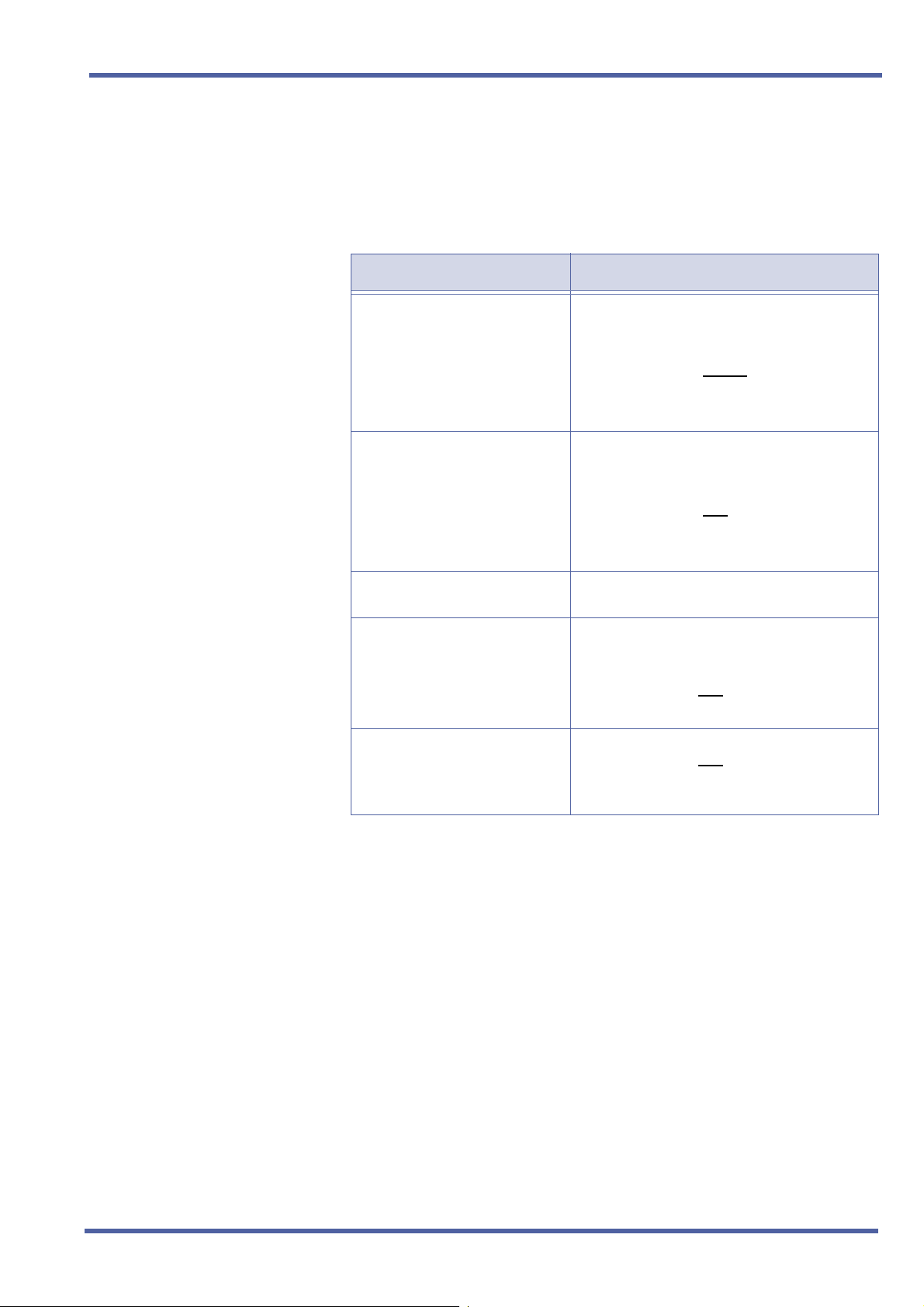
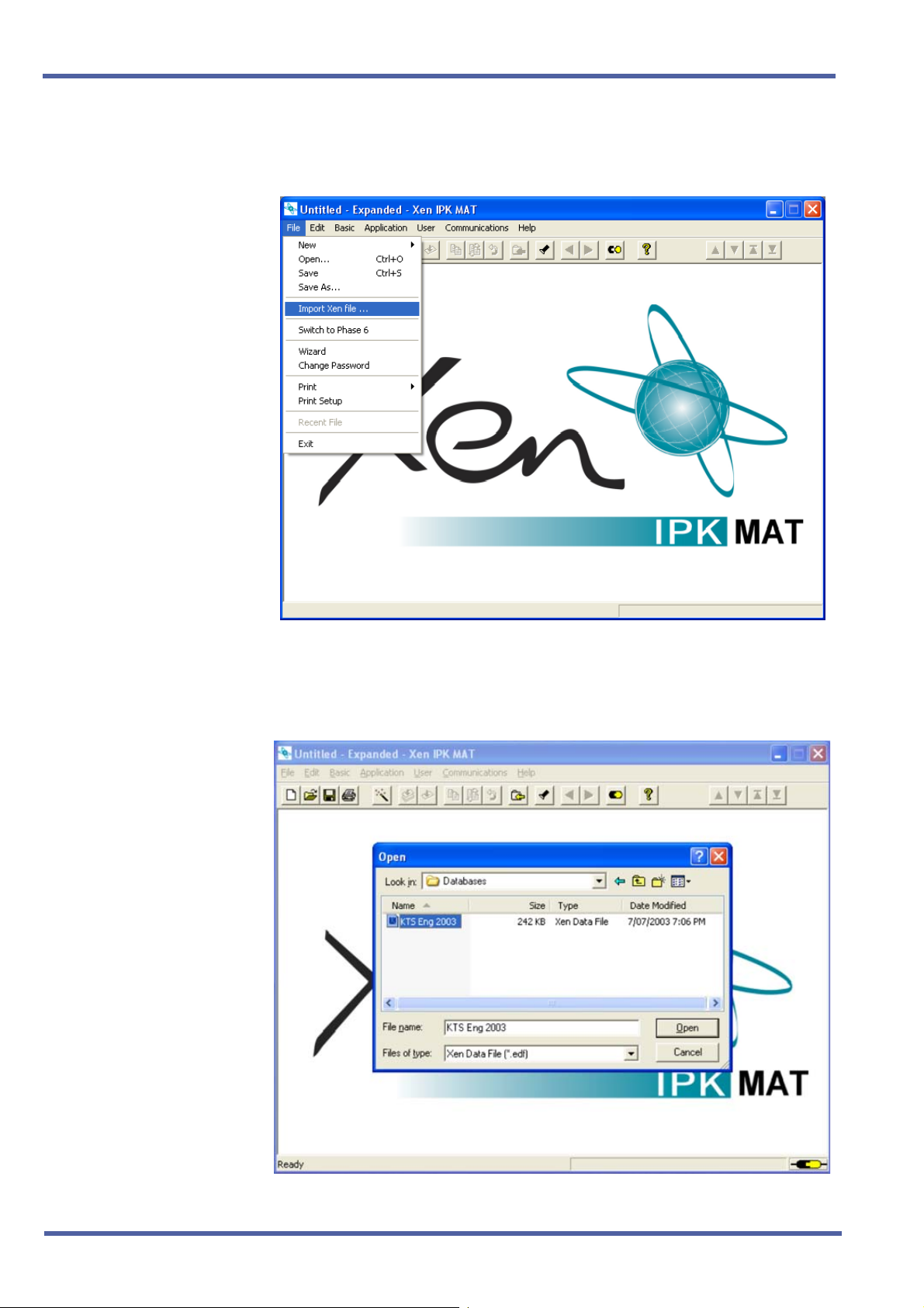
3. Select IPK, enter the password, and click OK to open Xen IPK MAT.
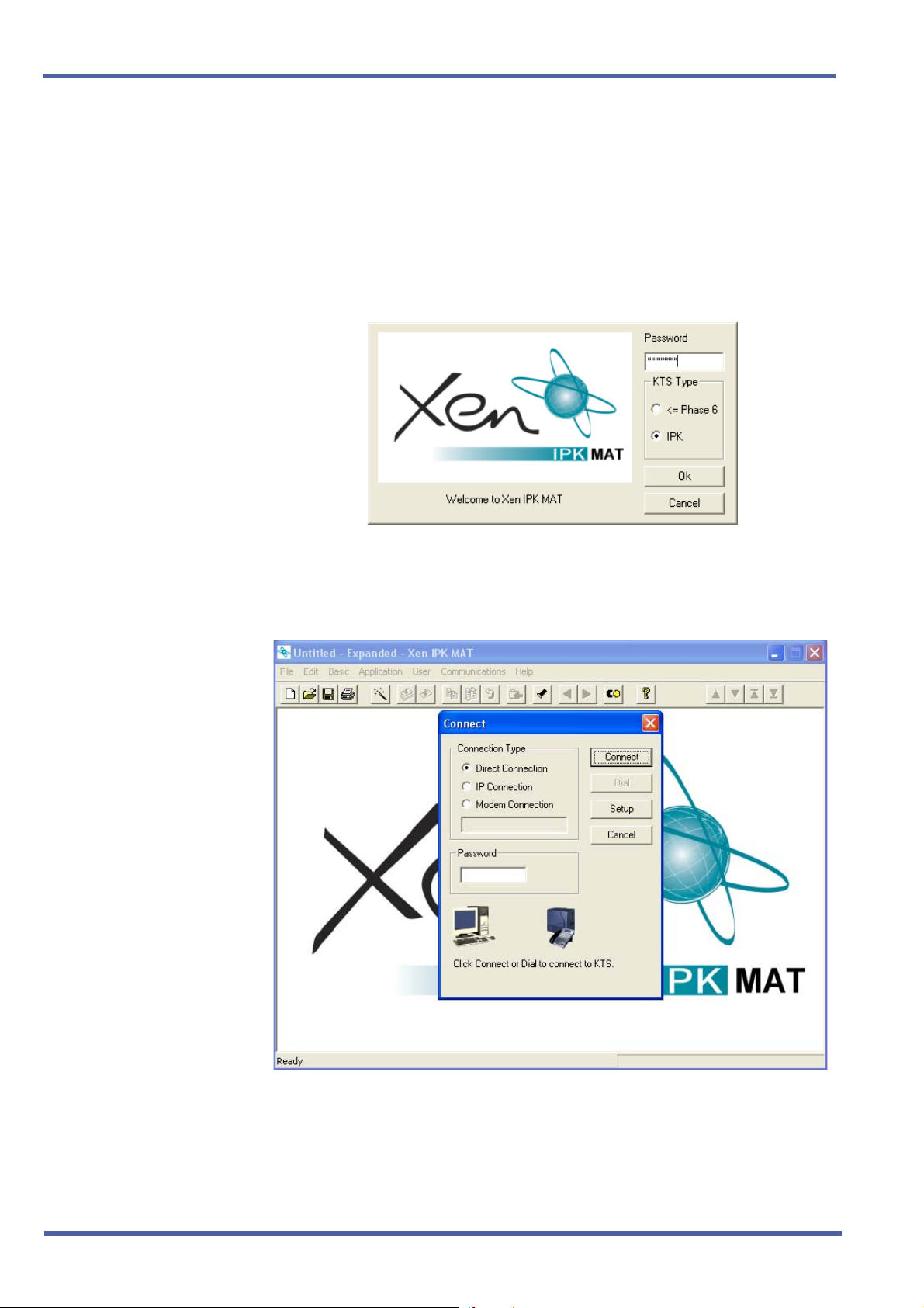
4. From the Communications Menu, Select Connect to connect to the
Xen Axis/Master system.
2 – Chapter 1 Direct Download from the Installed Xen System
Doc. No. 8283 - Release 1.0
September 2003
Enhancement Guide to Migrating from Xen Axis/Master to Xen IPK R1000
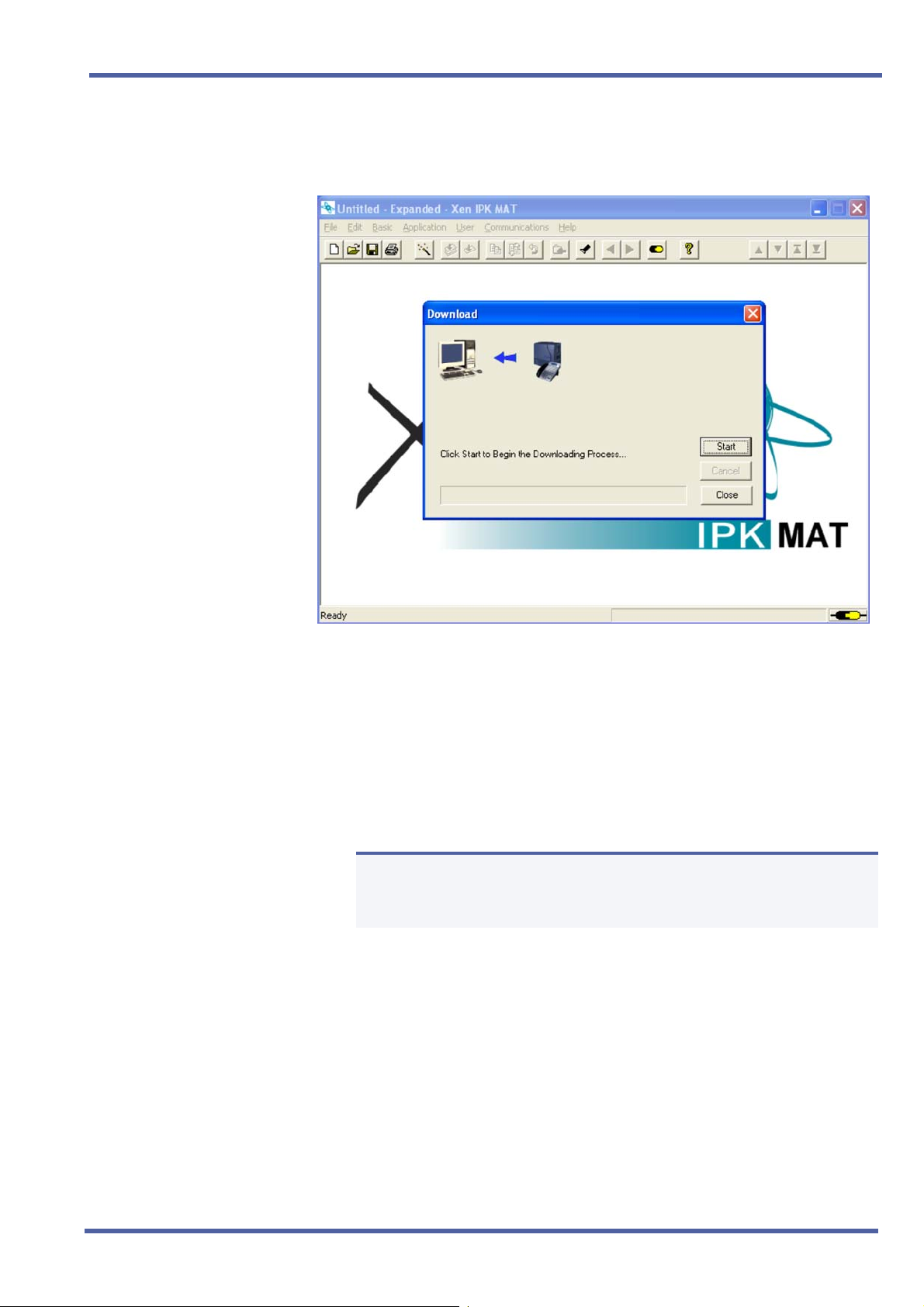
5. From the Communications menu, select Download and click Start to
download the database from the Xen Axis/Master system.
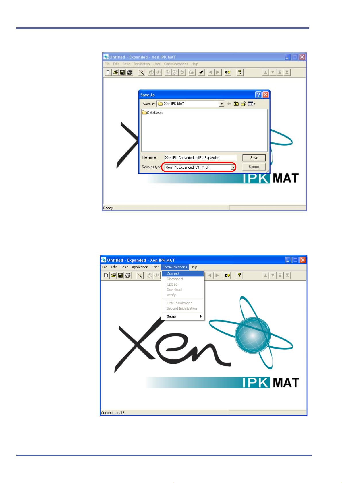
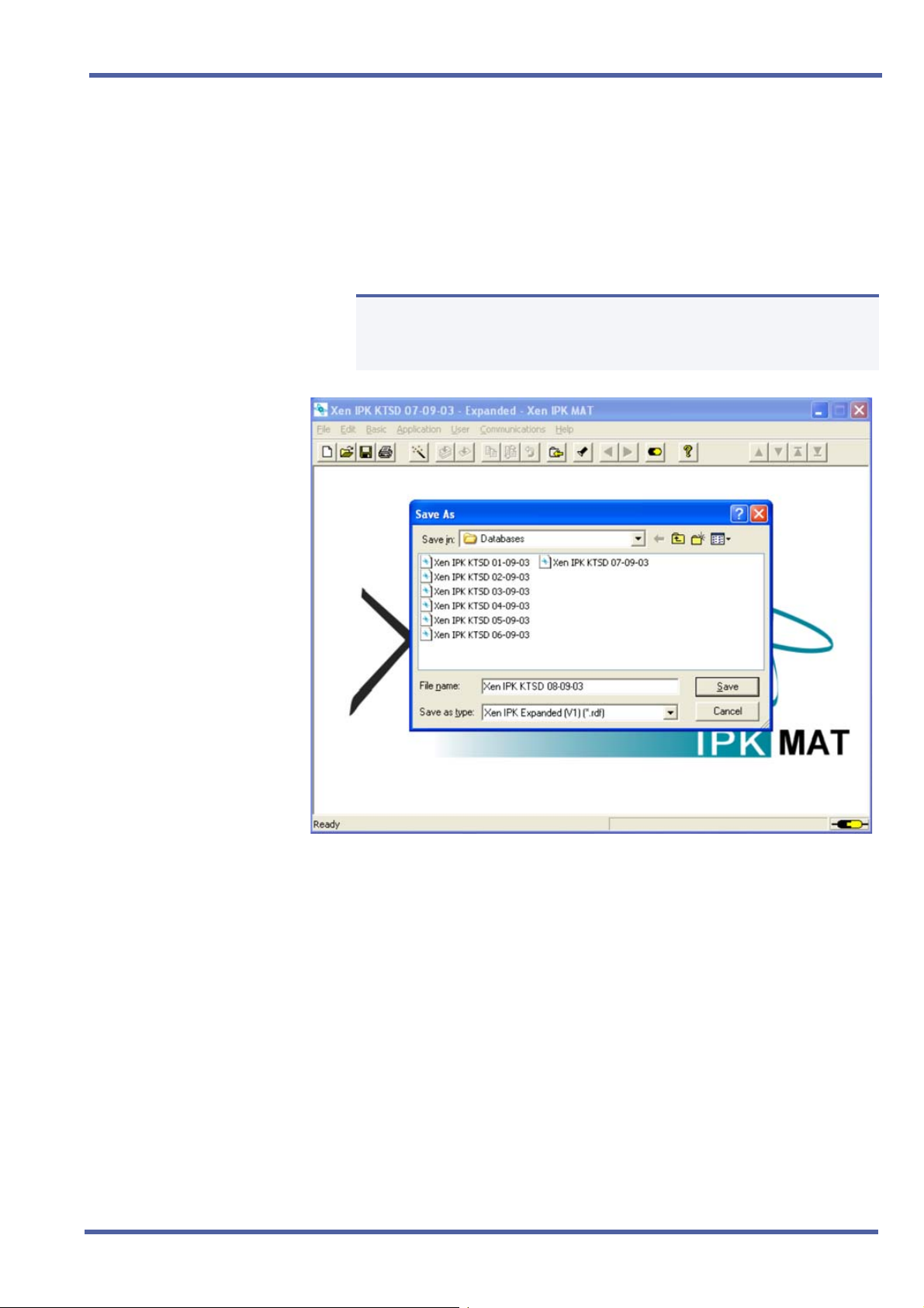
6. When the download is finished, select Save As from the File menu
and enter a file name.
When the system is to be saved as Xen IPK Basic, confirm that
Save As type is Xen IPK Basic (R1000) (*.rdf), and click Save.
When the system is to be saved as Xen IPK Expanded, confirm
that Save As type is Xen IPK Expanded (R1000) (*.rdf) and click
Save.
Only the Xen Axis system can be saved as Xen IPK Basic.
N
Doc. No. 8283 - Release 1.0
September 2003
Direct Download from the Installed Xen System Chapter 1 – 3
September 2003 NEC Business Solutions Ltd
7. From the Communications menu, select Disconnect to disconnect
from the Xen system.
4 – Chapter 1 Direct Download from the Installed Xen System
Doc. No. 8283 - Release 1.0
September 2003
Enhancement Guide to Migrating from Xen Axis/Master to Xen IPK R1000
8. Assign any other required system data assignment changes and from
the File menu, select Save if required.
9. Change hardware from the Xen Axis/Master system to the Xen IPK
system.
Upgrade Type Comments
Xen Axis to Xen IPK Basic Port
Package
Xen Axis to Xen IPK Expanded
Port Package
Xen Master to Xen IPK Basic
Port Package
Xen Master to Xen IPK
Expanded Port Package with
new Xen IPK KSUs
Xen Master to Xen IPK
Expanded Port Package without
new Xen IPK KSUs (Retrofit)
Replace the B48-U13 KSU hardware with the
following:
B64-U23 KSU
CPUI( )-U( ) ETU (without
ESI(8)-U( ) ETU in slot 1 *
Move all other hardware to new KSU.
Replace the B48-U13 KSU hardware with the
following:
B64-U23 KSU
CPUI( )-U( ) ETU (with
ESI(8)-U( ) ETU in slot 1 *
Move all other hardware to new KSU.
Not supported.
Replace the B64-U13 KSUs with the B64-U23
KSUs.
Replace the CPUB( )-U( ) ETU with the
CPUI( )-U( ) ETU with
Move all other hardware to new KSUs.
Replace the CPUB( )-U( ) ETU with the
CPUI( )-U( ) ETU with
Add Front Cover Extender [FCE-U( ) UNIT] to
each B64-U13 KSU/E64-U13 KSU.
PKU 192-UA)
PKU 192-UA)
PKU 192-UA.
PKU 192-UA.
* The ESI(8)-U( ) or ESIB(8)-U( ) ETU
Doc. No. 8283 - Release 1.0
September 2003
Direct Download from the Installed Xen System Chapter 1 – 5
September 2003 NEC Business Solutions Ltd
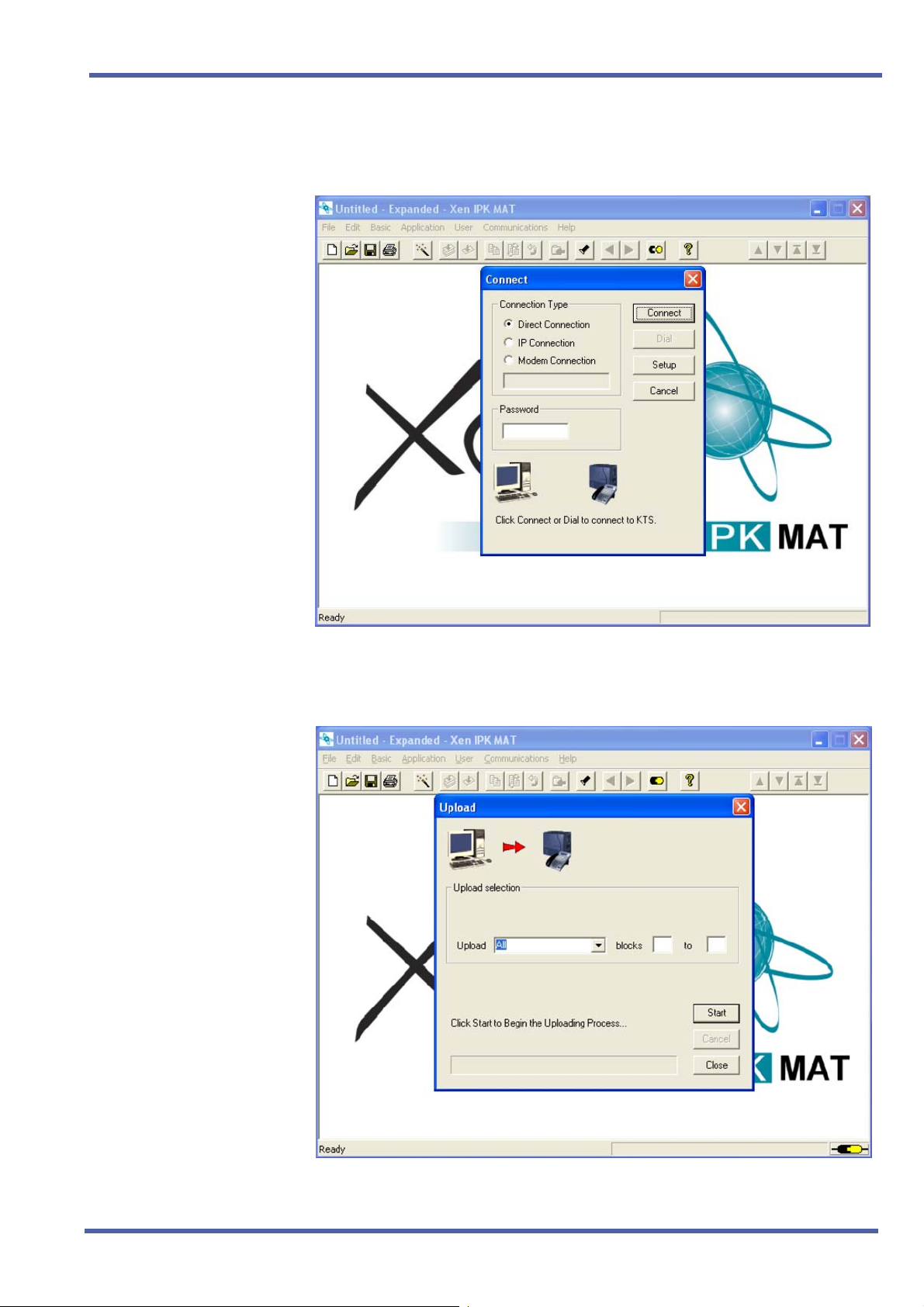
10. From the Communications menu, select Connect to connect the
Xen IPK.
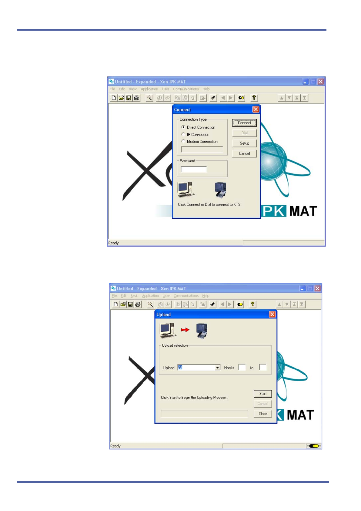
11. From the Communications menu, select Upload, and click Start.
6 – Chapter 1 Direct Download from the Installed Xen System
Doc. No. 8283 - Release 1.0
September 2003
Enhancement Guide to Migrating from Xen Axis/Master to Xen IPK R1000
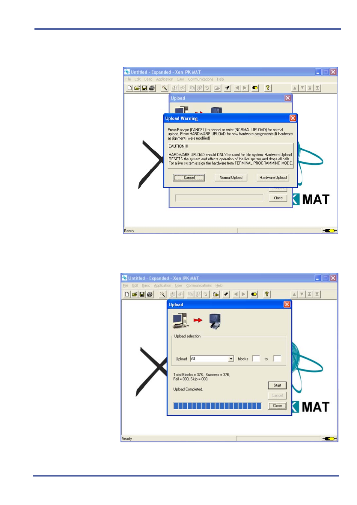
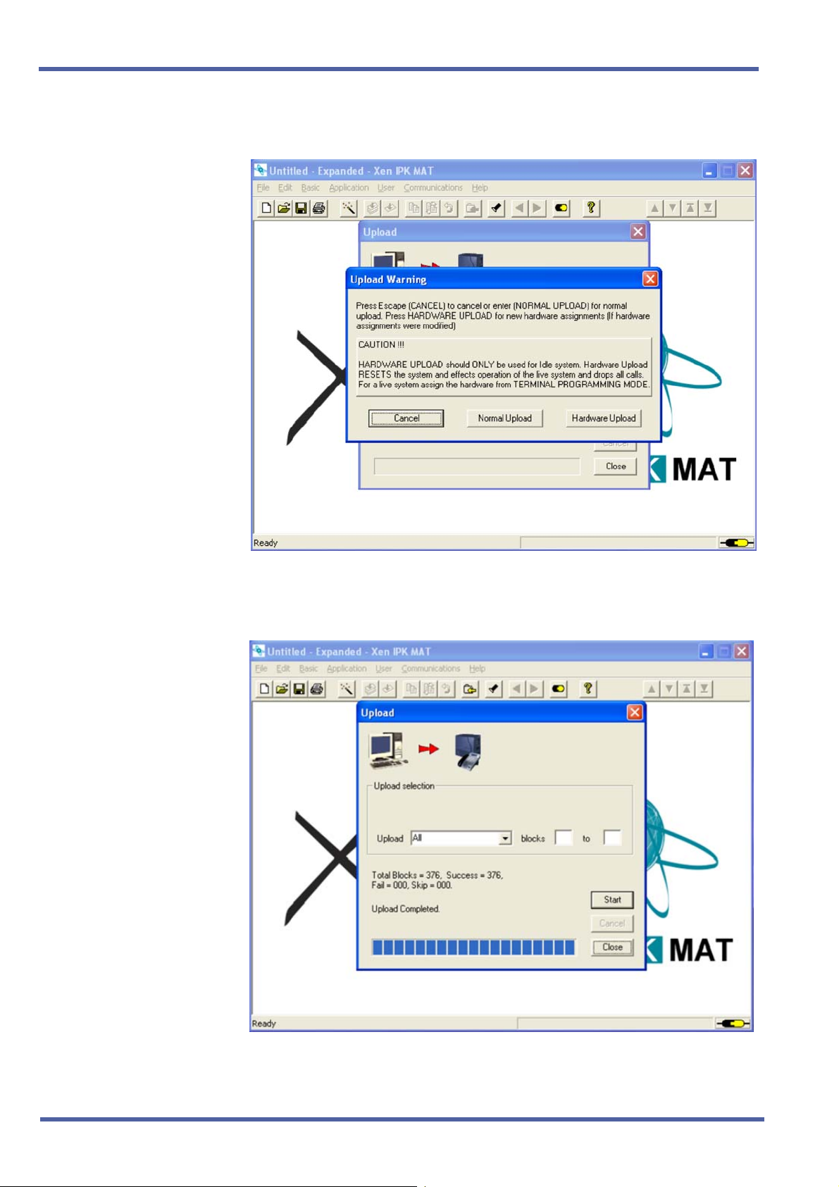
12. Click Hardware Upload.
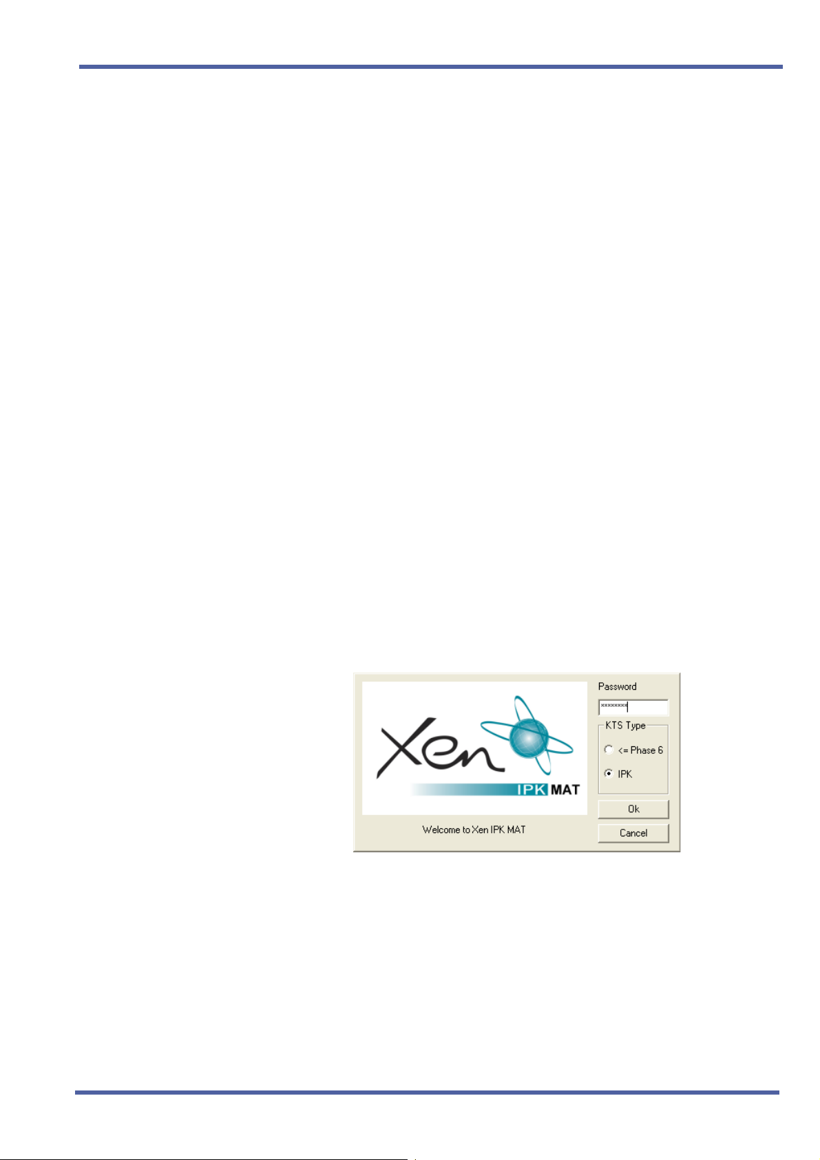
13. When Upload is complete, click Close.
Doc. No. 8283 - Release 1.0
September 2003
Direct Download from the Installed Xen System Chapter 1 – 7

September 2003 NEC Business Solutions Ltd
14. From the Communications menu, Select Disconnect to disconnect
from Xen IPK.
15. Reassign all settings recorded in Step 2, and confirm proper system
operation.
8 – Chapter 1 Direct Download from the Installed Xen System
Doc. No. 8283 - Release 1.0
September 2003
Enhancement Guide to Migrating from Xen Axis/Master to Xen IPK R1000
S
ECTION
IMPORT SAVED XEN
D
ATABASE USING A
P
REVIOUS VERSION OF
THE XEN AXIS/
M
ASTER MAT
3
1. Verify that the battery is connected to CN4 on Xen Master CPUB( )U( ) or Xen Axis MBD-U( ) Unit.
2. Confirm and record the following settings:
Answer Preset
Automated Attendant/DISA mode
Automatic Trunk-to-Trunk Transfer mode
Automatic Trunk-to-Trunk Transfer Outgoing Trunk
Background Music
Call Forward – All Calls, Busy, No Answer, Busy/No Answer, Off-
Premise/Split
Callback Messages
Customized Message Display
Day/Night Mode (System and Tenant)
Do Not Disturb
MIC Settings
Timed Alarm
The following memories are empty after the upgrade:
Last Number Redial Memory
Recorded messages in the VRS(4)-U( ) ETUs (messages must
be recorded again)
Store & Repeat/Save & Repeat
3. Select IPK, enter the password, and click OK to open Xen IPK MAT.
Doc. No. 8283 - Release 1.0
September 2003
Import Saved Xen Database Using a Previous Version of the Xen Axis/Master MAT Chapter 1 – 9
September 2003 NEC Business Solutions Ltd
4. From the File menu, select Import Xen Axis/Master file to import a
previously saved database.
5. Locate the directory where the Xen Axis/Master database is stored.
Select file name and click Open to import the database.
10 – Chapter 1 Import Saved Xen Database Using a Previous Version of the Xen Axis/Master MAT
Doc. No. 8283 - Release 1.0
September 2003
Enhancement Guide to Migrating from Xen Axis/Master to Xen IPK R1000
6. When the download is finished, select Save As from the File menu
and enter a file name.
When the system is to be saved as Xen IPK Basic, confirm that
Save as type is Xen IPK Basic (R1000) (*.rdf), and click Save.
When the system is to be saved as Elite IPK Expanded, confirm
that Save as type is Xen IPK Expanded (R1000) (*.rdf) and click
Save.
Only the Xen Axis system can be saved as Xen IPK Basic.
N
7. Assign any other required system data assignment changes and from
the File menu, select Save if required.
Doc. No. 8283 - Release 1.0
September 2003
Import Saved Xen Database Using a Previous Version of the Xen Axis/Master MAT Chapter 1 – 11

September 2003 NEC Business Solutions Ltd
8. Change hardware from the Xen Axis/Master system to the Xen IPK
system.
Upgrade Type Comments
Xen Axis to Xen IPK Basic Port
Package
Xen Axis to Xen IPK Expanded
Port Package
Xen Master to Xen IPK Basic
Port Package
Xen Master to Xen IPK
Expanded Port Package with
new IPK KSUs
Xen Master to Xen IPK
Expanded Port Package without
new Xen IPK KSUs (Retrofit)
Replace the B48-U13 KSU hardware with the
following:
B64-U23 KSU
CPUI( )-U( ) ETU (without
ESI(8)-U( ) ETU in slot 1 *
Move all other hardware to new KSU.
Replace the B48-U13 KSU hardware with the
following:
B64-U23 KSU
CPUI( )-U( ) ETU (with
ESI(8)-U( ) ETU in slot 1 *
Move all other hardware to new KSU.
Not supported.
Replace the B64-U13 KSUs with the B64-U23
KSUs.
Replace the CPUB( )-U( ) ETU with the
CPUI( )-U( ) ETU with
Move all other hardware to new KSUs.
Replace the CPUB( )-U( ) ETU with the
CPUI( )-U( ) ETU with PKU 192-UA.
Add Front Cover Extender [FCE-U( ) UNIT] to
each B64-U13 KSU/E64-U13 KSU.
PKU 192-UA)
PKU 192-UA)
PKU192-UA.
*The ESI(8)-U( ) or ESIB(8)-U ETU.
Doc. No. 8283 - Release 1.0
September 2003
12 – Chapter 1 Import Saved Xen Database Using a Previous Version of the Xen Axis/Master MAT
Enhancement Guide to Migrating from Xen Axis/Master to Xen IPK R1000
9. From the Communications menu, select Connect to connect to the
Xen IPK.
10. From the Communications menu, select Upload, and click Start.
Doc. No. 8283 - Release 1.0
September 2003
Import Saved Xen Database Using a Previous Version of the Xen Axis/Master MAT Chapter 1 – 13
September 2003 NEC Business Solutions Ltd
11. Click Hardware Upload.
12. When Upload is finished, Click Close.
14 – Chapter 1 Import Saved Xen Database Using a Previous Version of the Xen Axis/Master MAT
Doc. No. 8283 - Release 1.0
September 2003

Enhancement Guide to Migrating from Xen Axis/Master to Xen IPK R1000
13. From the Communications menu, select Disconnect to disconnect
from the Xen IPK.
14. Reassign all settings recorded in Step 2 and confirm proper system
operation.
Doc. No. 8283 - Release 1.0
September 2003
Import Saved Xen Database Using a Previous Version of the Xen Axis/Master MAT Chapter 1 – 15

September 2003 NEC Business Solutions Ltd
S
ECTION
UPGRADE P ROCEDURE
FOR MIFM-U( )
4
Upgrade Description
This ETU must be upgraded to firmware V5.00 or higher to be compatible
with the Xen IPK (R1000) system to support Caller ID Indication – 50 Caller
ID scroll buffers
The Caller ID scroll buffers are erased when firmware is upgraded.
N
Installation Precautions
WARNING
Observe the following precautions when installing the ETUs to avoid
damage to hardware due to static electricity or to being exposed to
hazardous voltages.
The ETUs and units used in this system make extensive use of CMOS
technology. CMOS technology is very susceptible to static; therefore,
extreme care must be taken to avoid static discharge when handling
ETUs and units.
When carrying a ETU or unit be sure to keep it in a conductive
polyethylene bag to prevent damage due to static electricity.
When handling a ETU or unit the installer must wear a grounded wrist
strap to protect the ETU or unit from static electricity.
Software Upgrade Procedure
Use the following procedure for software upgrade of the MIFM-U( ) ETU.
1. Remove the MIFM-U( ) ETU from the KSU.
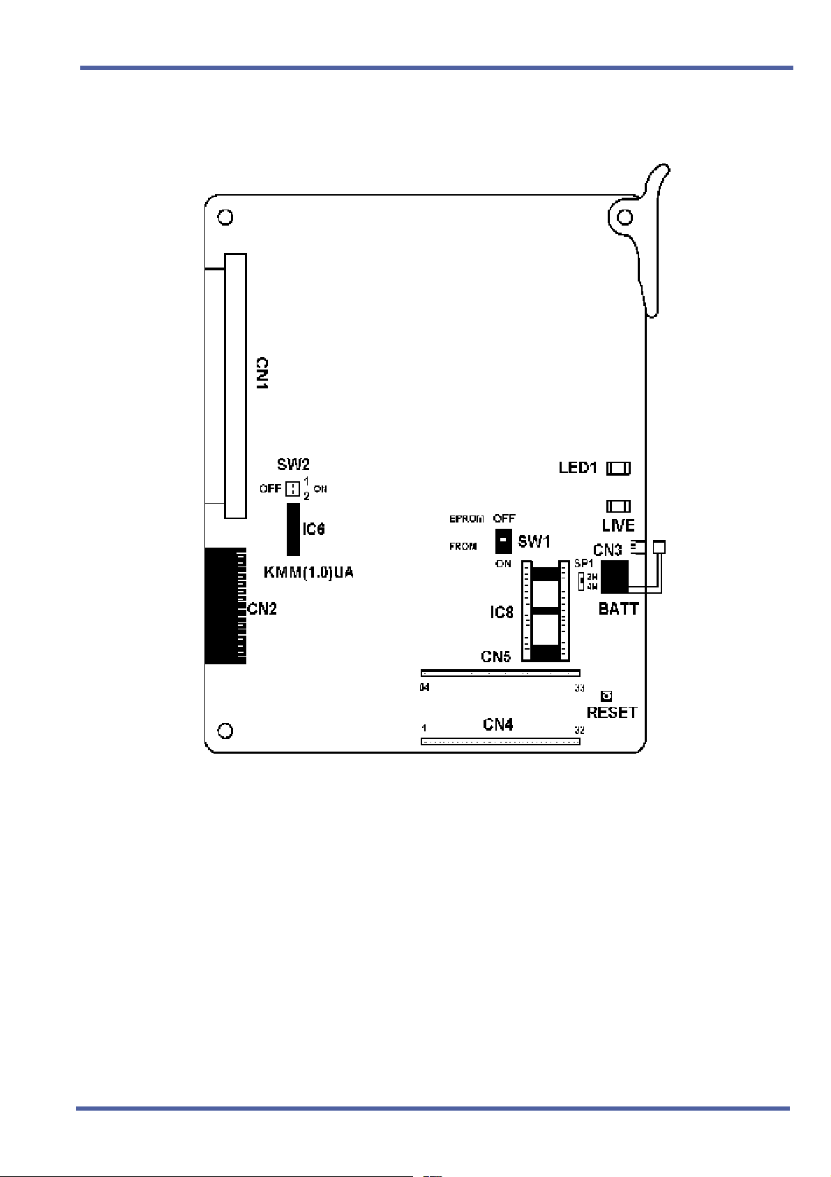
2. Mount the EPROM labelled “MIFM Rev 5.XX” on MIFM-U( ) card
(IC8). Refer to Figure 1-1: MIFM-U( ) ETU for a diagram of the card.
3. Set the switch SW1 to OFF (EPROM) and set the DIP SW2-1 and
SW2-2 to ON. Refer to Figure 1-1: MIFM-U( ) ETU for a diagram of the
card.
4. Install MIFM-U( ) ETU into same slot from Step 1 of the KSU. Notice
that LED 1 is winking or flashing.
5. After LED 1 goes off, pull out the MIFM-U( ) card from the KSU.
6. Remove the EPROM and set switch SW1 to ON (FROM) and set DIP
SW2-1 and SW2-2 to OFF.
16 – Chapter 1 Upgrade Procedure for MIFM-U( )
Doc. No. 8283 - Release 1.0
September 2003
Enhancement Guide to Migrating from Xen Axis/Master to Xen IPK R1000
7. Install the MIFM-U( ) into the same slot from Step 1 of the KSU.
Figure 1-1: MIFM-U( ) ETU
Software Verification for MIFM( )-U( ) ETU
To verify the current software version installed on the MIFM( )-U( ) ETU do
the following:
1. Go off-line.
2. Press LK8 + LK1 to access the Memory Block.
3. Press
4. Verify that the current software revision number is displayed.
5. Press
Doc. No. 8283 - Release 1.0
September 2003
Upgrade Procedure for MIFM-U( ) Chapter 1 – 17
N to locate the MIFM( )-U( ) ETU.
P to go back on line.

September 2003 NEC Business Solutions Ltd
S
ECTION
5
Upgrade Description
UPGRADE P ROCEDURE
FOR PRT(1)-U( ) ETU
The PRT(1)-U( ) ETU must be updated to firmware V2.12 or higher to be
compatible with the Xen IPK (R1000) system for individual channel
assignment and PRT B channel-to-trunk group assignment.
Installation Precautions
WARNING
Observe the following precautions when installing the ETUs to avoid
damage to hardware due to static electricity or to being exposed to
hazardous voltages.
The ETUs and units used in this system make extensive use of CMOS
technology. CMOS technology is very susceptible to static; therefore,
extreme care must be taken to avoid static discharge when handling
ETUs and units.
When carrying a ETU or unit be sure to keep it in a conductive
polyethylene bag to prevent damage due to static electricity.
When handling a ETU or unit the installer must wear a grounded wrist
strap to protect the ETU or unit from static electricity.
PRT Software Chip Installation
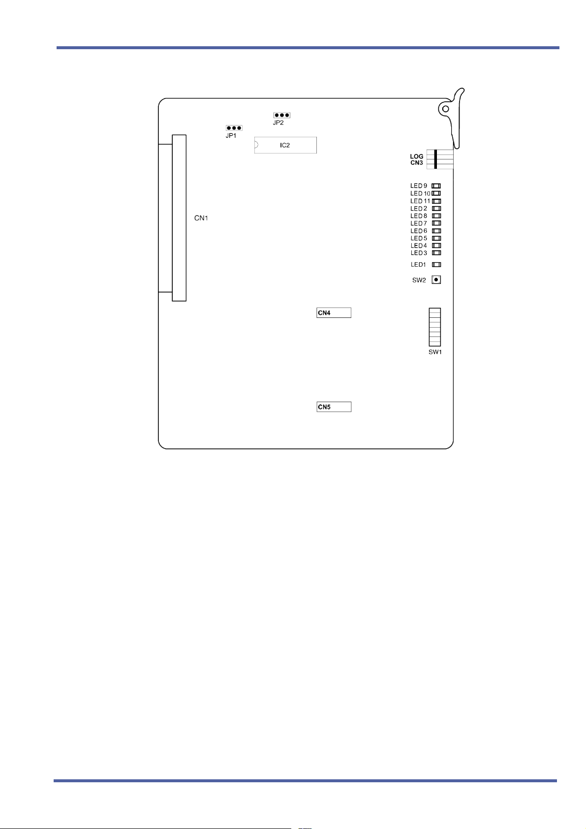
1. Remove the PRT(1)-U( ) ETU from the system.
This card can be removed with the system power on.
N
2. Remove the old chip located on IC2.
3. Install the new PRT chip on IC2.
Ensure that the notch on the chip lines up with the notch on
the socket.
N
This ETU must be updated to firmware V2.12 or higher to
be compatible with the Xen IPK for individual
Channel Assignment and PRT B Channel-to-Trunk Group
Assignment.
18 – Chapter 1 Upgrade Procedure for PRT(1)-U( ) ETU
Doc. No. 8283 - Release 1.0
September 2003
Enhancement Guide to Migrating from Xen Axis/Master to Xen IPK R1000
Doc. No. 8283 - Release 1.0
September 2003
4. Install the PRT(1)-U( ) ETU in the KSU.
Software Verification
To verify that the software revision was installed:
1. Go Off-Line.
2. Press LK8 + LK1.
3. Press
4. Verify that the current software version number is displayed.
5. Press
N to locate the PRT(1)-U( ) ETU.
P to go back On-line.
Upgrade Procedure for PRT(1)-U( ) ETU Chapter 1 – 19

September 2003 NEC Business Solutions Ltd
S
ECTION
ADDING AN EARTH
C
ONNECTION
6
The Xen IPK B64-U23 KSU must be properly and permanently grounded,
due to it being an ESELV (Earthed Safety Extra Low Voltage) compliant
product. The protective earth terminal located at the right rear corner of the
B64-U23 KSU must have a permanent conneciton to protective earth.
1. Connect the gorunding cable (green/yellow wire) to the ground
terminal on the right side of the Basic KSU. The grounding cable
(locally provided) must hav an AWG greater than #16.
Figure 1-2: KSU Grounding
2. Provide a suitable ground inside of the building in accordance with
local telephone company procedures.
3. If no suitable ground is available, a ground rod should be installed in
accordance with the operating procedures of the local telephone
company.
The protective Earth and Telecommunications Reference Conductor
N
(TRC) is permanently linked within the KSU, therefore, the Xen system
does not require the connectIon of an external TRC.
20 – Chapter 1 Adding an Earth Connection
Doc. No. 8283 - Release 1.0
September 2003

Hardware Description and
Specifications for Xen IPK
1.1 B64-U23 KSU
1.1.1 Basic KSU
The B64-U23 KSU provides service for outside lines,
Attendant Consoles, and interconnection of the station
terminals. The B64-U23 KSU has two fixed and eight
flexible slots. The first fixed slot is reserved for the CPUI( )U( ) ETU in the basic KSU or for the EXP-U( ) ETU in
expansion KSUs. The second fixed slot is for the MIFAU( ) ETU or MIFM-U( ) ETU.
The P64-U13 PSU (power supply unit), backup batteries,
[one external MOH/BGM input, one external paging zone
output] and three PFT relays are included with each KSU.
1.1.2 Expansion KSUs
Chapter 2
The B64-U23 KSU is also used as the expansion unit that
can be attached to the basic KSU to provide additional
ports. Two expansion units can be added to the Xen IPK
system. Each expansion KSU provides eight flexible slots
and accommodates 8-, 16-, 24-channel interface cards.
The P64-U13 PSU (power supply unit), backup batteries,
and three PFT relays are included with each KSU.
Doc. No. 8283 - Release 1.0
September 2003
Hardware Description and Specifications for Xen IPK Chapter 2 – 21
September 2003 NEC Business Solutions Ltd
The installation instructions provided in this chapter apply
to the basic B64-U23 KSU and the expansion B64-U23
KSUs unless otherwise specified.
1.2 CPUI( )-U( ) ETU
Description
The CPUI( )-U( ) ETU is the Central Processing Unit for the Xen IPK
system. This ETU has a Central Processing Unit and a
Microprocessing Unit.
A 32-bit microprocessor executes the programs stored on the Flash
ROM ICs of the MPU unit. This controls the entire system when data
is transferred to and from other ETUs.
This ETU provides the following items:
Time Division Switch (TDSW)
Static Random Access Memory (SRAM)
32-bit Processor
4-channel DTMF Receiver (PBR)
Sixteen 4-party Conference Circuits
Figure 2-1: B64-U23 KSU
Internal (digital music) Music-on-Hold source
External Music-on-Hold input (also used for station background
music)
Flash ROM
Call Progress and DTMF Tone Generator
22 – Chapter 2 Hardware Description and Specifications for Xen IPK
Doc. No. 8283 - Release 1.0
September 2003

Xen IPK R1000 Upgrade Procedure for Xen Axis/Master Xen IPK
Memory Backup Battery (Retains memory for approximately
21 days)
Key Function (KF)/Multifunction (MF) Registration
Installation
Each system must have one CPUI( )-U( ) ETU in the CPU/EXP slot
of the basic B64-U23 KSU. Refer to Figure 2-2: CPUI( )-U( ) ETU
Switch Settings.
WARNING
If the CPUI( )-U( ) ETU is installed in slots S1~S8, it will be damaged!
Figure 2-2: CPUI( )-U( ) ETU Switch Settings
Doc. No. 8283 - Release 1.0
September 2003
Hardware Description and Specifications for Xen IPK Chapter 2 – 23

September 2003 NEC Business Solutions Ltd
Switch Settings
Refer to Table 1-1: CPUI( )-U( ) ETU Default Switch Settings.
Table 1-1: CPUI( )-U( ) ETU Default Switch Settings
SW1-1 SW1-2 Description
Off Off Normal Operation
On Off Flash ROM load from COM1 port
Off On Factory Test
On On Flash ROM load from EPROM
SW1-3 Description
Off MF Mode
On KF Mode
SW2 Description
Momentary
Switch
System Reset
SW3-1 Description
On System boot by EPROM
Off System boot by Flash ROM
SW3-2 Description
N/A Not Used
WARNING
Pressing SW2 interrupts all service and causes a second initialization.
Use this switch only as a last resort.
Connectors
Before programming System Data, the battery must be connected to
CN4 to allow memory retention if a power failure or brownout occurs.
When a brownout or power failure does occur, and the battery
backup circuit is not activated, System Data resets to the default
values, all stations in the system reset to the default values, and all
data programmed on individual stations is cleared.
24 – Chapter 2 Hardware Description and Specifications for Xen IPK
Doc. No. 8283 - Release 1.0
September 2003

Xen IPK R1000 Upgrade Procedure for Xen Axis/Master Xen IPK
When a CPUI( )-U( ) ETU is installed in the system, the clock/
calendar must be set. This also applies when battery backup fails for
any reason.
When CPUI( )-U( ) ETU is removed for long term storage,
disconnect the battery from CN4. This prevents the battery from
discharging completely. The fully charged battery retains memory for
approximately 21 days.
The CPUI( )-U( ) ETU has the following connectors:
CN1 Connects to the backboard
CN2 Connects to the ISA-bus
CN3 Connects to CN2 on the EXP-U( ) ETU using the
expansion cable
CN4 Connects to the memory backup battery using the
battery cable (factory installed)
CN5 Connects to CN1 of the CLKG-U( ) Unit
CN6 Connects to CN2 of the CLKG-U( ) Unit
LED Indications
LED Description On Flashing Off
LIVE CPU status Operation stopped
(Power On)
LED2 Power status System Power On Not Used System
Normal
Operation
No Power
Power Off
Replacing Memory Backup
The CPUI( )-U( ) ETU provides memory backup for approximately
21 days. The Ni-Cad battery should be replaced about every two
years.
1. Remove the battery cable from CPUI( )-U( ) ETU
CN4. Refer to Figure 2-2: CPUI( )-U( ) ETU Switch
Settings.
2. Connect the cable from the new battery to CN4 on the
CPUI( )-U( ) ETU.
3. Turn off the KSU power.
4. Remove the CPUI( )-U( ) ETU from the slot in the
KSU.
5. Use a suitable cutting tool to cut the tie wrap and
remove the old battery.
6. Fasten the new battery with a tie wrap.
7. Install the CPUI( )-U( ) ETU again.
Doc. No. 8283 - Release 1.0
September 2003
Hardware Description and Specifications for Xen IPK Chapter 2 – 25
8. Turn on the KSU power.

September 2003 NEC Business Solutions Ltd
1.3 PKU 192-UA (Port Key Unit)
The Port Key Unit allows the system to be configured as an
Expanded Port Package. When the PKU 192-UA is not installed, the
system is configured as a Basic Port Package; when it is installed,
the system is configured as an Expanded Port Package.
The PKU 192-UA is installed in the IC30 socket.
Description
Basic Terminals (Telephones)
Shared Call Arrival (CAR) Keys with Basic Terminals
Dedicated Call Arrival (CAR) Keys
Basic Terminals + Call Arrival (CAR) Keys
Basic Trunks
Universal Slots
Shared MIF Slots with Universal Slots
Dedicated MIF Slot
4 Basic Terminals includes Wireless (PHS) and Voice Mail stations.
Basic Port
Package
Expanded
Port
Package
32 120 4
24 112
40 0
72 120
16 64
24 24
22
11
26 – Chapter 2 Hardware Description and Specifications for Xen IPK
Doc. No. 8283 - Release 1.0
September 2003

Xen IPK R1000 Upgrade Procedure for Xen Axis/Master Xen IPK
1.5 ESIB(8)-U( ) ETU
Description
The ESIB(8)-U( ) ETU is the basic Electronic Station Interface ETU
that provides an 8-channel interface for Multiline Terminals,
Attendant Consoles and Single Line Telephone Adapter SLT(1)-U( )
ADP. This ETU can be expanded to 16 channels by installing the
ESIE(8)-U( ) ETU.
Figure 2-3: ESIB(8)-U( ) ETU
Installation
A maximum of eight ESIB(8)-U( ) ETUs can be installed in slots
S1~S8 in any system KSU.
Refer to KSU Power-Based ETU Quantity Limitations in the Xen
IPK Features and Specifications manual for Universal Slots.
Switch Settings
SW1 resets the ETU.
Doc. No. 8283 - Release 1.0
September 2003
Hardware Description and Specifications for Xen IPK Chapter 2 – 27
September 2003 NEC Business Solutions Ltd
LED Indications
Live LED indications are listed below.
Blinking Red Normal Operation
Steady Red Operation Stopped (power On)
Off No Power
LED1 indications are listed below.
Steady Red Some port(s) busy
Off All ports idle
Connectors
The ESIB(8)-U( ) ETU has three connectors:
CN1 Connects to the backboard
EXCN1 Connects to EXCN1 on the ESIE(8)-U( ) ETU
EXCN2 Connects to EXCN2 on the ESIE(8)-U( ) ETU
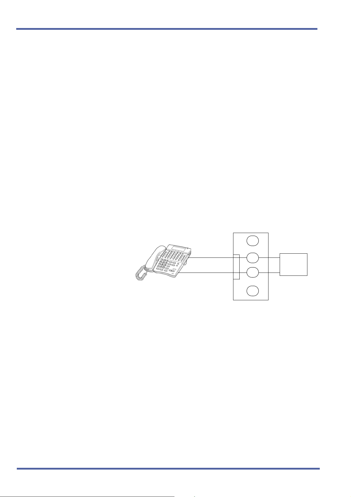
Connections
BK
RD
GN
To Telephone
YL
RJ-11
Figure 2-4: ESIB(8)-U( ) ETU Connection
To
MDF
28 – Chapter 2 Hardware Description and Specifications for Xen IPK
Doc. No. 8283 - Release 1.0
September 2003
Xen IPK R1000 Upgrade Procedure for Xen Axis/Master Xen IPK
1.6 ESIE(8)-U( ) ETU
Description
The ESIE(8)-U( ) ETU is the expansion Electronic Station Interface
ETU that provides an additional 8-channel interface for Multiline
Terminals, Attendant Consoles and Single Line Telephone Adapter
SLT(1)-U( ) ADP. This expansion ESI ETU is piggybacked on the
ESIB(8)-U( ) ETU.
Figure 2-5: ESIE(8)-U( ) ETU
Installation
A maximum of five ESIE(8)-U( ) ETUs can be installed in slots
S1~S8 in any system KSU.
Refer to KSU Power-Based ETU Quantity Limitations in the Xen IPK
Doc. No. 8283 - Release 1.0
September 2003
Hardware Description and Specifications for Xen IPK Chapter 2 – 29
Features and Specifications manual for Universal Slots.
September 2003 NEC Business Solutions Ltd
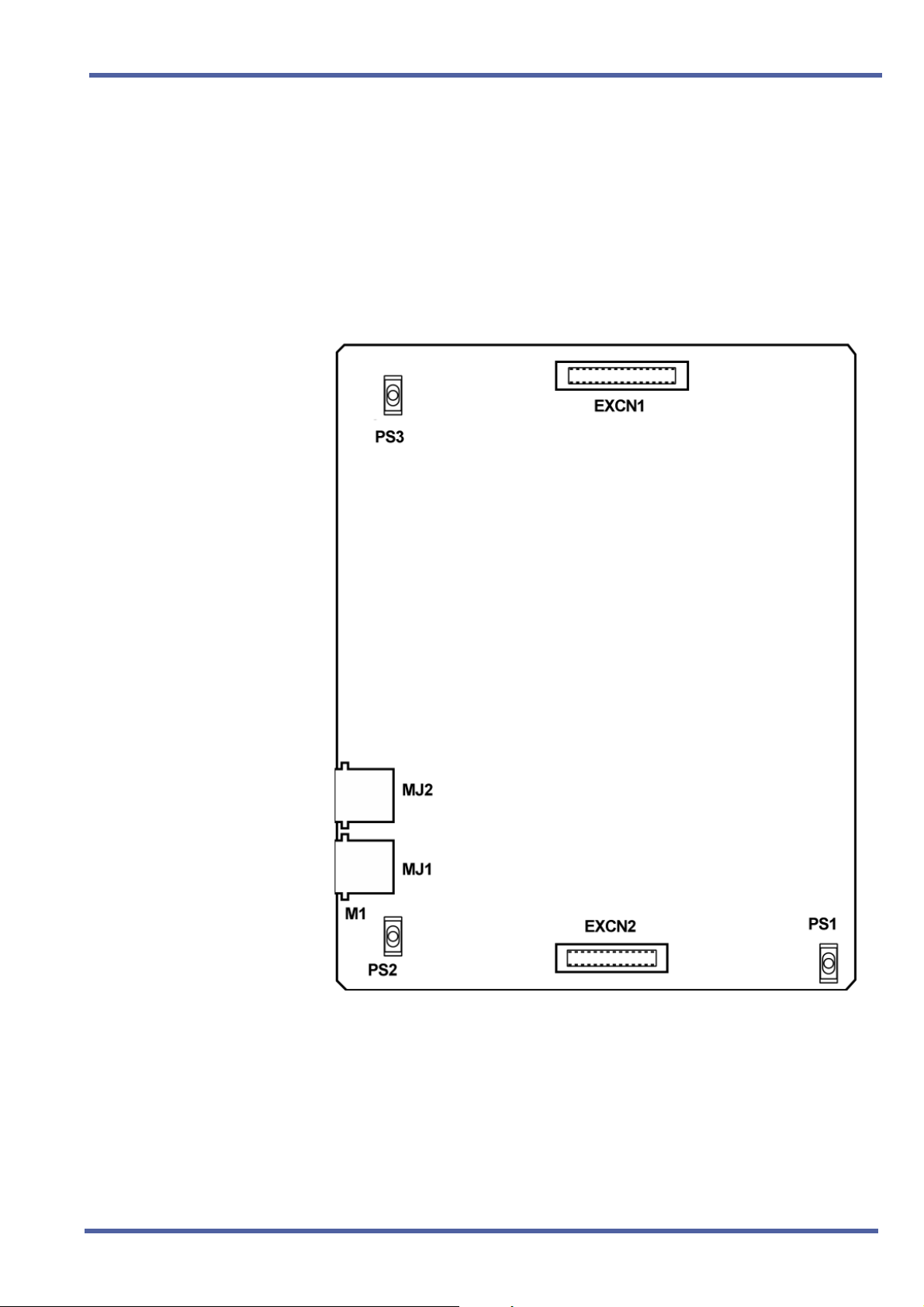
Connectors
The ESIE(8)-U( ) ETU has four connectors:
EXCN1 Connects to EXCN1 on the ESIB(8)-U( ) ETU
EXCN2 Connects to EXCN2 on the ESIB(8)-U( ) ETU
MJ1 Connects to MDF (eight ESI ports)
MJ2 Connects to MDF (eight ESI ports)
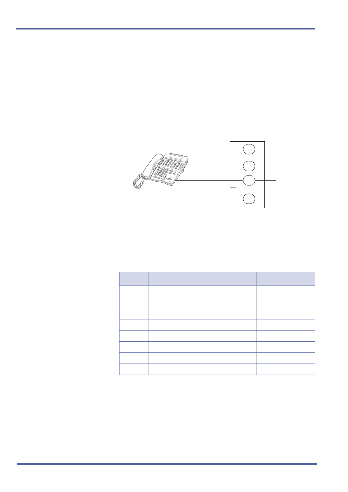
Connections
BK
RD
GN
To Telephone
YL
RJ-11
Figure 2-6: ESIE(8)-U( ) ETU Connection
To
MDF
Pin Assignments
The following pin assignments are used to connect eight Multiline
Terminals to the ESIE(8)-U( ) ETU.
MJ1 Pin Signal Signal Name Pin Colour
1T4 CH3–TipWHT–BLU
2T3 CH2–TipBLU–WHT
3T2 CH1–TipWHT–ORN
4 R1 CH0–Ring ORN–WHT
5T1 CH0–TipWHT–GRN
6 R2 CH1–Ring GRN–WHT
7 R3 CH2–Ring WHT–BRN
8 R4 CH3–Ring BRN–WHT
30 – Chapter 2 Hardware Description and Specifications for Xen IPK
Doc. No. 8283 - Release 1.0
September 2003

Xen IPK R1000 Upgrade Procedure for Xen Axis/Master Xen IPK
MJ2 Pin Signal Signal Name Pin Colour
1T8 CH7–TipWHT–BLU
2 T7 CH6–Tip BLU–WHT
3T6 CH5–TipWHT–ORN
4 R5 CH4–Ring ORN–WHT
5T5 CH4–TipWHT–GRN
6 R6 CH5–Ring GRN–WHT
7 R7 CH6–Ring WHT–BRN
8 R8 CH7–Ring BRN–WHT
Doc. No. 8283 - Release 1.0
September 2003
Hardware Description and Specifications for Xen IPK Chapter 2 – 31

September 2003 NEC Business Solutions Ltd
THIS PAGE INTENTIONALLY LEFT BLANK
32 – Chapter 2 Hardware Description and Specifications for Xen IPK
Doc. No. 8283 - Release 1.0
September 2003

Features and Specifications
for Xen IPK
Chapter 3
Attendant Transfer A-15
FEATURE
DESCRIPTION
SYSTEM
AVAILABILITY
Attendant Transfer permits efficient call transfers in the system using an
Attendant Multiline Terminal equipped with one to four Attendant Add-On
Console(s). Transferred calls can be voice announced, camped-on (when
the station is busy), or directly transferred to ring at stations. After a
programmed time, all unanswered transferred calls return to the Attendant
with distinct audible and visual indications.
Terminal Type
Any display Multiline Terminal programmed as an Attendant Position.
OPERATING
PROCEDURES
Required Components
DCR-60-1A/DCU-60-1A Console
From the Attendant Position with a CO/PBX call in progress:
1. Press the DSS key on the Attendant Add-On Console or the Attendant
Position for the desired station.
2. Wait for ringback tone or voice announcement.
3. Press
Position. The call is transferred.
4. Hang up.
5. After time-out, when the transferred call is not answered, a recall tone
is received at the Attendant Position; and the LED on the assigned
CO/PBX line key or Call Appearance Key returns to flashing green.
6. Press the CO/PBX line key with the flashing green LED to return to
the call.
N on the Attendant Add-On Console or on the Attendant
Doc. No. 8283 - Release 1.0
September 2003
Features and Specifications for Xen IPK Chapter 3 – 33

September 2003 NEC Business Solutions Ltd
SERVICE
CONDITIONS
RELATED
FEATURES LIST
General
When a Transfer/Camp-On is denied, the call remains on hold at the
Attendant Position Multiline Terminal.
The outside line key LED flashes green on the station receiving the
Transfer/Camp-On, when the line appears on that station. The Large
LED also flashes green and the LED or the ANS key flashes red.
An Attendant trying to Transfer/Camp-On a call to a station may be
denied, when the Multiline Terminal is busy and receiving Tone
Override.
Use Memory Block 4-66 (MOH or Ring Back Tone Selection) to
assign MOH or Ring Back Tone for the outside party when a trunk
call is placed on hold by the Transfer key on a D
term
Series i, hook
flash from a Single Line Telephone, or the Transfer or Hold keys
at a PHS station.
Feature
Number
A-11 Attendant Add-On Console
A-12 Attendant Camp-On
Feature Name
GUIDE TO FEATURE
PROGRAMMING
Order
and
Shortcut
4
¶+BTS
¶+BTS
¶+BTS
¶+BM
¶+AU
¶+BTD
System Transfer/Camp-On Selection
CO Transfer Ring Pattern Selection
CO Transfer Ring Tone Selection
Attendant Add-On Console Transfer/Camp-On
Recall Time Selection
Automated Attendant Delay Announcement Hold
Tone Selection
Attendant Add-On Console Key Selection
A-25 Automatic Release
System Data Name
Memory
Block
1-1-11
1-1-13
1-1-14
1-1-64
1-4-17
1-6-05
Function
1-8-07
Attendant
Page-Line
Key
1-8-08
Station
Page-Line
Key
¶+BTS
¶+BTT
When the system is at default this Memory Block must be programmed for the feature to be used.
4
34 – Chapter 3 Attendant Transfer A-15
Class of Service (Station) Feature Selection 2
MOH or Ring Back Tone Selection
1-8-08 4-2
4-66
Doc. No. 8283 - Release 1.0
September 2003

Xen IPK Features and Specifications for Xen IPK
Call Arrival (CAR) Keys C-3
FEATURE
D
ESCRIPTION
SYSTEM
AVAILABILITY
OPERATING
PROCEDURES
Call Arrival (CAR) keys are available software extensions as part of 120
station numbers on the Expanded Port Package. The Basic Port Package
provides 32 station numbers and 40 CAR ports. A Call Arrival extension
assigned to a line key, can appear and ring on an individual station or
multiple stations. When a call is directed to a CAR, any station with the CAR
can answer. This ensures that every call to that group is answered promptly.
Multiline Terminals may have several CAR extension appearances
depending on the application.
Terminal Type
All Multiline Terminals
Required Components
None
To answer an incoming outside call to the Call Arrival key on an
outside or internal line call with Off-Hook Ringing assigned:
1. Receive off-hook ringing.
2. Press CAR key. The first call is placed on hold, and the CAR is
answered.
3. The incoming call resides on a Call Appearance (CAP) key, or CO
Line key when it is assigned on the telephone.
To answer an incoming outside line call to the Call Arrival key on an
internal call with Ringing Line Preference:
1. Go on-hook on an internal call.
2. Go off-hook to answer incoming outside line call to a CAR key.
Doc. No. 8283 - Release 1.0
September 2003
Call Arrival (CAR) Keys C-3 Chapter 3 – 35

September 2003 NEC Business Solutions Ltd
SERVICE
CONDITIONS
General
Incoming outside line calls can ring on a CAR. When the call is
answered, it resides on a CAP (or CO Line key). The CAR becomes
idle for another incoming call or continues to flash when another call is
waiting to be answered. When a Call Appearance key (or CO Line key)
is unavailable, an outside line call to a Call Arrival key cannot be
answered.
Incoming internal calls to a Call Arrival key can be answered without
using a Call Appearance key. The ICM lamp (when provided) indicates
a call, and when the call is put on hold, flashes at the Conference key.
Go off-hook, press the Speaker key when Ringing Line Preference is
assigned, press the flashing Call Arrival key, or press the Answer key
to answer Calls ringing at a Call Arrival key.
Call Arrival Keys can be set for Call Forward - All Call and Call
Forward - Busy/No Answer.
Call Arrival keys can be set for Call Forward – Off - Premise.
Off-Hook Ringing can be provided for calls ringing into CAR keys.
CAR keys can be assigned as a station hunting master number and/or
as a member of a Station Hunt group.
A BLF indication is provided on an Attendant Add-On Console for
incoming calls.
A CAR key can be called using a DSS key from an Attendant Add-On
Console or a DSS key at a Multiline station.
An internal call to a CAR key is ring only. Voice announce is not
available.
Restrictions
The Xen IPK Expanded Port Package system can provide 112 Call
Arrival keys. This number is shared with 120 station ports.
The Xen IPK Basic Port Package system can contain 64 Call Arrival
keys. This number includes 40 dedicated CAR key ports and 24
Shared with station ports. When 64 CAR keys are assigned, eight port
numbers can be assigned for hardware extension numbers.
Two software packages (Basic Port Package and Expanded Port
Package) are available for the Xen IPK system using the CPUI( )U( ) ETU. Refer to the following table for maximum system
capacities for each software package.
36 – Chapter 3 Call Arrival (CAR) Keys C-3
Doc. No. 8283 - Release 1.0
September 2003

Xen IPK Features and Specifications for Xen IPK
Item
Basic Port
Package
Expanded
Port Package
Notes
Basic Terminals (Phones)
Shared Call Arrival (CAR) Keys with Basic Terminals
Dedicated Call Arrival (CAR) Keys
Basic Terminals + Call Arrival (CAR) Keys
Basic Trunks
Universal Slot
Shared MIF Slots with Universal Slots
Dedicated MIF Slot
RELATED
FEATURES LIST
GUIDE TO FEATURE
Feature
Number
C-2 Call Appearance (CAP) Keys
PROGRAMMING
32 120
24 112
40 0
72 120
16 64
24 24
22
11
Feature Name
Order
and
Shortcut
¶+BK
4 Call Arrival Key Block Assignment
System Data Name
¶+BA Access Code (1- or 2-Digit) Assignment
Memory
Block
1-2-04
1-1-46/47/
Function
001
Attendant
Page-Line
48
¶+BS
¶+BTM
¶+BTM
¶+BTM
¶+BTD Attendant Add-On Console Key Selection
¶+BTM SIE/CAR Ringing Line Preference Selection
¶+BTT Station to Call Appearance Block Assignment
4 When the system is at default this Memory Block must be programmed for the feature to be used.
4 Station Number Assignment
4 Line Key Selection for Telephone Mode
4 Extension Line Key Ring Assignment (Day Mode)
4 Extension Line Key Ring Assignment (Night
Mode)
4-10
4-12
4-37
4-38
1-6-05
4-41
4-43
1-8-07
Key
1-8-08
Station
Page-Line
Key
Doc. No. 8283 - Release 1.0
September 2003
Call Arrival (CAR) Keys C-3 Chapter 3 – 37

September 2003 NEC Business Solutions Ltd
Caller ID - Incoming C-6
FEATURE
DESCRIPTION
SYSTEM
AVAILABILITY
Caller ID displays the calling party telephone number and/or name on the
LCD of the Multiline Terminal for CO incoming calls. Up to 16 Multiline
Terminals that have CO ringing and/or CAR appearance assigned can
automatically display Caller ID information during an incoming call. Multiline
Terminals that are not part of these 16 terminals can display Caller ID if they
have the appropriate class of service by manual operation. After the CO call
has been answered the Caller ID information will follow the call wherever it is
transferred to.
When the MIFM-U( ) ETU with KMM( )UA is installed, the Caller ICD
information can be displayed for the last 50 incoming calls by using
the Caller ID Scroll key, if assigned.
Terminal Type
All Multiline Terminals with an LCD.
Required Components
COID(4)-U( ) ETU, COID(8)-U( ) ETU, BRT(4)-U( ) ETU, or PRT(1)-U( )
ETU to receive Caller ID indication from a central office.
MIFM-U( ) ETU with KMM( )UA installed when Caller ID Scrolling or Call
Return are desired.
OPERATING
PROCEDURES
To display a stored Caller ID:
Press the Scroll/Directory key to display the last incoming Caller ID.
Repeatedly press the Scroll/Directory key to display additional
Caller ID names/numbers. (A maximum of 50 Caller ID names/numbers
are displayed.)
The Scroll key is programmed in System Programming using the Line Key
Selection for the Telephone Mode Memory Block. Refer to the System
Programming Manual for instructions.
To return a call to the name/number displayed on the LCD:
Go off-hook. The system automatically accesses an outside line and dials the
ID number displayed on the LCD.
Doc. No. 8283 - Release 1.0
September 2003
38 – Chapter 3 Caller ID - Incoming C-6

Xen IPK Features and Specifications for Xen IPK
Manual Operation:
For Multiline Terminals without automatic Caller ID display but which have an
appropriate class of service assigned, the following key sequences will also
display Caller ID indication: Feature key + CO key, Feature key + CAR key,
or Feature key + Answer key.
SERVICE
CONDITIONS
Data Assignment:
Caller ID Indication
Use Memory Block 7-1 (Card Interface Slot Assignment) to specify the
COID(4)-U( ), COID(8)-U( ), BRT(4)-U( ) or PRT(1)-U( ) ETU.
Use Memory Block 1-1-78 (Caller ID Display Assignment for System
Mode) to assign up to 15 Multiline Display Terminals to display Caller ID
indication for incoming calls.
Use Memory Block 4-49 (Caller ID Display for CAR Key Assignment) to
assign one Multiline Terminal per CAR Key to display Caller ID
indication for incoming calls.
Use Memory Block 3-44 (Caller ID Display Assignment for CO/
PBX Line) to assign the Caller ID Display for normal incoming CO/
PBX calls.
Use Memory Block 3-71 (Caller Name Display Assignment) to specify
whether the network name or speed dial name match is to
be displayed.
Use Memory Block 1-8-08 [Class of Service (Station) Feature Selection
2] Page 4 LK3 to Allow (LED On) or Deny (default: LED Off) Caller ID.
Use Memory Block 1-8-08 [Class of Service (Station) Feature Selection
2] Page 4 LK4 to Allow (LED On) Caller ID Number display or Deny
(default: LED Off) to display the Caller ID Name, when Name and
Number are received.
Use Memory Block 1-8-08 [Class of Service (Station) Feature Selection
2] Page 5 LK7 to Allow (LED On) or Deny (default: LED Off) to display
on two rows of the MLT. Both the name and number must be received
from the network. Page 4 LK4 selects the position of the name or
number on the Display for stations assigned to the Class of Service.
When Page 4 LK4 is On, the number is displayed on the top line of the
display. When Page 4 LK4 is Off, the name is displayed on the top line
of the display.
Use Memory Block 4-17 (Station to Class of Service Feature
Assignment) to make each station Class of Service Assignment.
Use Memory Block 4-01 [CO/PBX Ring Assignment (Day Mode)] or 4-
02 [CO/PBX Ring Assignment (Night Mode)] to make the CO/PBX
ringing assignments.
Use Memory Block 3-53 (Caller Name Indication Selection) to allow the
name (NAM) (default: NUM) to be displayed When system speed dial
buffers are assigned number and name and when the Caller ID number
information matches an assigned speed dial number.
Doc. No. 8283 - Release 1.0
September 2003
Caller ID - Incoming C-6 Chapter 3 – 39

September 2003 NEC Business Solutions Ltd
When the name is not included in the Caller ID information, Memory
Block 3-53 (Caller Name Indication Selection) compares the Caller ID
information with the dial data in the speed dial area. When the numbers
match, the name in the speed dial area is used as the name.
When a CAR key is assigned on the Multiline Terminal and a DIT/ANA
or VRS/Automated Attendant transferred call is received at the CAR,
the following assignments are required:
z Use Memory Block 4-41 (SIE/CAR Ringing Line Preference Selection)
to specify whether to allow (default: YS) or deny (NO) Ringing Line
Preference (go off-hook or press speaker key) on all telephones that
are assigned to CAR keys.
z Assign the Multiline Terminal with the CAR key as part of the Caller
ID group.
Scrolling Caller ID with Return Call
Use Memory Block 7-3-04 [MIF (Caller ID) Assignment) to specify
Scrolling and/or Out Dial function to the MIFM-U( ) ETU with
KMM( )UA Unit.
Use Memory Block 4-44 (Caller ID Preset Dial Outgoing CO Selection)
to assign the Trunk Group, Route Advance Group, or Closed
Numbering Group that is seized for Caller ID Outgoing Calls.
Use Memory Block 4-12 (Line Key Selection for Telephone Mode) to
assign the Scroll Key to a line key for each Multiline Terminal using the
Scroll Feature.
Restrictions
To receive Caller ID Indication, the COID(4)/(8)-U( ) ETU, BRT(4)-U( )
ETU or PRT(1)-U( ) ETU must be installed.
SIE incoming calls do not support Caller ID Indication even when the
Multiline Terminal is ringing.
The user can press the Feature key and then the flashing red CO line
key (incoming CO call), CAR key or
A maximum of 16 stations can display Caller ID. - Five users can access
the Scroll function at the same time. IN USE is displayed on the
Multiline terminal of another user that tries to access it.
A maximum of 13 characters can be displayed on the LCD for Caller ID
Name/Number.
O key to display Caller ID.
Caller ID scrolling and automatic dial out features require installation of
the MIFM-U( ) ETU with attached KMM( )UA Unit.
When a call transferred to a station goes unanswered and is transferred
again, Caller ID information is not stored in the scrolling bin at that
station.
40 – Chapter 3 Caller ID - Incoming C-6
Doc. No. 8283 - Release 1.0
September 2003

Xen IPK Features and Specifications for Xen IPK
General:
Caller ID Indication
When the CO line key, CAR key or ANSWER key is flashing red
(Incoming CO call), the user can press Feature + Key to display Caller
ID even when Caller ID is not normally displayed.
When the telephone company sends the caller name and number, the
name or the number is displayed on the LCD while the Multiline
Terminal is ringing. When the telephone company sends the caller
number only, it is displayed on the top line of the LCD while the
Multiline Terminal is ringing.
A maximum of 15 Multiline Terminals can be assigned to display Caller
ID for normal incoming CO calls system-wide. A sixteenth Multiline
Terminal can be assigned to display Caller ID for normal incoming CO
calls per CO line. These 16 Multiline Terminals constitute a Caller ID
group. An answered call can be transferred to any station in the
system, and Caller ID is displayed at that station.
Press the green line key where the CO call resides during a CO call, to
verify the Caller ID. When the telephone company provides both
Name and Number (depending on the system assignment) they are
displayed for 5 seconds, followed by the remaining information.
When the telephone company sends the caller name and number, the
name or the number is displayed on the LCD while the Multiline
Terminal is ringing. When the telephone company sends the caller
number only, it is displayed on the top line of the LCD while the
Multiline Terminal is ringing.
When system speed dial buffers are assigned number and name, the
name can be displayed when the Caller ID number information
matches a speed dial number. This is only applicable for the first 100
(000 - 099) system speed dials when the system has been set to 1000
speed dials and first 80 (00 to 79) when the system has been set to
100 system speed dials. Memory Block 3-53, Caller ID Name
Indication assignment is used to allow this.
Caller ID Speed Dial matching will not take place if the speed dial
number is incorrectly entered e.g., missing the Area Code.
A caller ID name matched from a system speed dial buffer will be
displayed in preference to a caller ID name received from the network.
When a Multiline Terminal is busy, the Caller ID is displayed for an
incoming call.
When a Multiline Terminal is set for Do Not Disturb, the Caller ID is
displayed for incoming calls.
When a Multiline Terminal receives multiple incoming calls, the first
Caller ID is displayed. After the first call is answered, the second Caller
ID is displayed.
Doc. No. 8283 - Release 1.0
September 2003
Caller ID - Incoming C-6 Chapter 3 – 41

September 2003 NEC Business Solutions Ltd
The Caller ID Indication disappears:
z When an incoming call is answered.
z When an internal or ring transfer call is received.
z When Feature Access, DSS, Redial, or Feature key is pressed.
The Caller ID number is printed on the SMDR printout for incoming
calls that are answered at stations that can display Caller ID data. The
name is not printed.
When a station is engaged in a voice over, whisper page, or broker's
call, the station can display Caller ID until the process ends.
When an incoming call is answered before Caller ID is sent, the Caller
ID is not displayed.
The following incoming calls display Caller ID on a Multiline terminal:
z Ordinary CO Calls
z DIT/ANA calls
z VRS/AA calls
z Ring Transfer calls
z CAR calls
z ACD/UCD calls
z Calls with delayed ringing
When a Multiline Terminal displays Caller ID with off hook ringing and
receives another incoming CO call, the Caller ID changes to the
second caller.
When trunk name indication is assigned, the data in Memory Block 3-
00 (Trunk Name/Number Assignment) is displayed on the Multiline
Terminal assigned for Caller ID indication even when a terminal
receives a caller name and number.
When hotline/prime line is set in Memory Block 4-23 (Prime Line/
Hot Line Assignment, a station user can originate an outgoing call
using Caller ID.
Scrolling Caller ID with Return Call
When the Scroll key is used, a maximum of 50 Caller IDs can be
stored in System Memory. When 50 Caller IDs are stored and
an additional call is answered, the first Caller ID is erased
from System Memory. Press the Scroll key to display the stored
Caller IDs. When you go Off-hook, the displayed Caller ID is
automatically dialled.
When Scroll key is not pressed with five seconds of the last press, the
LCD returns to idle, and Caller ID disappears.
When an outgoing call is made using the Scroll function, the call follows
Code Restriction, Digit Restriction, and Least Cost Routing (LCR) or
Automatic Carrier Routing (ACR). The LCR or ACR feature is required
for the Scroll function to operate properly.
42 – Chapter 3 Caller ID - Incoming C-6
Doc. No. 8283 - Release 1.0
September 2003

Xen IPK Features and Specifications for Xen IPK
The DIRE key provided with the Dterm Series i Terminals performs
the same function as the Caller ID Scroll key.
Caller ID data is not stored when the following conditions apply:
RELATED
FEATURES LIST
z Mobile
z Pay Phone
z Out of Area
z Private
z Data Error
Call from a Mobile Telephone.
Caller ID is sent from a pay phone.
Data is sent from a CO that cannot process Caller ID data.
Calling party disables Caller ID information for the called
party.
The data stream includes an error.
When Out of Area or Private characters are received, the MIFM-U( )
ETU does not store them in the Scroll Key buffer.
Feature
Number
Feature Name
A-22 Automatic Carrier Routing
C-17 Class of Service
D-14 Do Not Disturb (DND)
I-7 ISDN-BRI Trunk Connections
I-8 ISDN-PRI Trunk Connections
L-3 Least Cost Routing (LCR)
Doc. No. 8283 - Release 1.0
September 2003
Caller ID - Incoming C-6 Chapter 3 – 43

September 2003 NEC Business Solutions Ltd
GUIDE TO FEATURE
PROGRAMMING
Order
and
Shortcut
¶+BS
¶+BS
¶+AI
¶+BTS
¶+BCT
¶+BCT
¶+AI
¶+AI
¶+BTT
¶+BTT
¶+BTM
System Data Name
Card Interface Slot Assignment
MIF (ANI/Caller ID) Assignment
Caller ID Display Assignment for System Mode
4 Class of Service (Station) Feature Selection 2
DIT Assignment
ANA Assignment
Caller ID Display Assignment for CO/PBX Line
Caller Name Indication Selection
CO/PBX Ring Assignment (Day Mode)
CO/PBX Ring Assignment (Night Mode)
Line Key Selection for Telephone Mode
1-8-07
Memory
Block
7-1
7-3-04
1-1-78
1-8-08 4-3, 4-4,
3-42
3-43
3-44
3-53
4-01
4-02
4-12
Function
Attendant
Page-Line
Key
1-8-08
Station
Page-
Line Key
5-7,
6-5
¶+BTT
¶+BTM
¶+BTM
¶+AI
¶+AI
4 When the system is at default this Memory Block must be programmed for the feature to be used.
Station to Class of Service Feature Assignment
Extension Line Key Ring Assignment (Day Mode)
Extension Line Key Ring Assignment (Night Mode)
Caller ID Preset Dial Outgoing CO Selection
Caller ID Display for CAR Key Assignment
4-17
4-37
4-38
4-44
4-49
44 – Chapter 3 Caller ID - Incoming C-6
Doc. No. 8283 - Release 1.0
September 2003

Xen IPK Features and Specifications for Xen IPK
Dterm Series i Multiline Terminals D-19
FEATURE
D
ESCRIPTION
SYSTEM
A
VAILABILITY
The D
friendly functions. With advanced digital circuitry, these terminals consist of
distinct models to meet users’ diverse telephone terminal needs.
Terminal Type
DTR-16LD-1A (BK)/(WH) TEL
DTR-32D-1A (BK)/(WH) TEL
DTR-16D-1A (BK)/(WH) TEL
DTR-8D-1A (BK)/(WH) TEL
DTR-2DT-1A (BK) TEL
DCR-60-1A (BK)/(WH) CONSOLE
Required Components
ESI(8)-U( ) ETU
ESIB(8)-U( ) ETU
ESIE(8)-U( ) UNIT
Optional Components
AD(A)-R( ) UNIT (Adapter for Call Recording)
AP(A)-R( ) UNIT (Analogue Port Adapter [without Ringer])
AP(R)-R( ) UNIT (Analogue Port Adapter [with Ringer])
CT(A)-R( ) UNIT (TAPI Adapter connect by RS-232C)
CT(U)-R( ) UNIT (TAPI Adapter connect by USB)
term
Series i Multiline Terminals provide ergonomic form and user-
WM-R( ) UNIT (Wall Mount Unit)
ACA-U( ) UNIT (AC Adapter)
Doc. No. 8283 - Release 1.0
September 2003
Dterm Series i Multiline Terminals D-19 Chapter 3 – 45

September 2003 NEC Business Solutions Ltd
OPERATING
PROCEDURES
Dedicated Function
Keys
Line/Feature Access/
Programmable
Feature Access Key
LCD (3x24) Yes Yes Yes Yes No
Call/Message
Indicator
Adjustable Base Yes Yes Yes Yes No
Built-in Wall Mount Yes Yes Yes Yes Yes
Headset Jack (Built-in) Yes Yes Yes Yes No
DESI Label by LCD Yes No No No No
Receiver Volume Control for:
Refer to individual feature for details.
Specifications
DTR-16LD-1A DTR-32D-1A DTR-16D-1A DTR-8D-1A DTR-2DT-1A
11 11 11 11 9
16 32* 16 8 2
Yes Ye s Yes Ye s Ye s
Handset Yes Yes Yes Yes Yes
Speakerphone Yes Yes Yes Yes Yes
Headset Yes Yes Yes Yes No
Ring Volume Control Yes Yes Yes Yes Yes
LCD Contrast Control Yes Yes Yes Yes No
Housing Colour White or Black White or Black White or Black White or Black Black
Soft Keys Yes Yes Yes Yes No
* A maximum of 24 keys may be programmed as Line Keys.
46 – Chapter 3 Dterm Series i Multiline Terminals D-19
Doc. No. 8283 - Release 1.0
September 2003

Xen IPK Features and Specifications for Xen IPK
SERVICE
CONDITIONS
General
term
The D
Series i Multiline Terminals with an adjustable display offer
soft key operation. The LCD panel has three lines of display, each
with 24 characters. Standard features include headset jacks, wall
mount units, and adjustable-base units.
term
The D
Series i Multiline Terminals support dedicated function keys
to provide easy one-touch access to the most common telephone
operations. These keys include: Feature, Recall, Conference,
Redial, Hold, Transfer, Answer, Speaker, Microphone, Directory,
and Message. Directory and Message keys are not available on the
DTR-2DT-1A (BK) TEL.
The dial pad is detachable allowing for easy customisation for a foreign
language or for Automatic Call Distribution (ACD) applications.
With the DTR-16LD-1A( ) TEL, the 16-Line Keys are labelled by the
LCD by assignment in system data. The LCD also supports the LED
status for trunks, Call Appearance Keys (CAP), DSS/BLF keys, and
select Feature keys/Feature Access keys.
Use Memory Block 4-68 (Line Key Name Assignment) to assign
names to each LCD Line Key of the DTR-16LD-1A( ) TEL Telephone.
Up to eight characters can be assigned.
term
The LCD of the D
Series i Multiline Terminals provide a volume bar
indication, while adjusting the following volume levels or controls:
z Speaker Volume
z Handset/Headset Volume
z BGM Volume
z Ring Volume/Off Hook Ring Volume
z LCD Contrast
Doc. No. 8283 - Release 1.0
September 2003
The MIC Key controls the built-in microphone during
speakerphone mode and controls the handset mute feature
during handset/headset operation.
The Directory Key performs the same function as the Caller ID
Scroll Key.
The Message Key acts as a Voicemail access key to call the
Voicemail pilot number.
Dterm Series i Multiline Terminals D-19 Chapter 3 – 47

September 2003 NEC Business Solutions Ltd
Restrictions
For compatibility of Adapter Units and Terminals, refer to the following
table:
Terminal
Adapter Unit DTR-16LD-1A DTR-32D-1A DTR-16D-1A DTR-8D-1A DTR-2DT-1A
AD(A)-R( ) X X X X –
AP(A)-R( ) X X X X –
AP(R)-R( ) X X X X –
CT(A)-R( ) X X X X –
CT(U)-R( ) X X X X –
Button Units
BS()-R() UNIT X X X X –
Other
WM-R() UNITXXXX–
ACA-U( ) UNIT X X X X –
X = Compatible
– = Non-compatible
Up to two adapters can be installed in a D
term
Series i Multiline Terminal
(except DTR-2DT-1A). For compatibility of multiple adapter units, refer
to the following table.
AD(A)-R( ) AP(A)-R( ) AP(R)-R( ) CT(A)-R( ) CT(U)-R( )
AD(A)-R( )
AP(A)-R( )
AP(R)-R( )
CT(A)-R( )
CT(U)-R( )
X = Compatible
X -XX *1
X- XX *1
XXX -
X X *1 X *1 -
XXXX
- = Non-compatible
*1 = The Voice Application of CT(U)-R( ) cannot be used when installed with
AP(A/R)-R( ) UNIT.
48 – Chapter 3 Dterm Series i Multiline Terminals D-19
Doc. No. 8283 - Release 1.0
September 2003

Xen IPK Features and Specifications for Xen IPK
The ACA-U( ) UNIT (AC Adapter) is required when any of the
term
following adapters are installed in a D
z AP(R)-R()
z CT(A)-R( )
z CT(U)-R()
z DCR-60-1A( ) Console
Series i Multiline Terminal:
RELATED
FEATURES LIST
GUIDE TO FEATURE
ROGRAMMING
P
The WM-R
installed in a D
() UNIT (Wall Mount Unit) is required when any adapter is
term
Series i Multiline Terminal and the terminal is to be
wall mounted.
Feature
Number
Feature Name
A-7 Ancillary Device Connection
D-20 DTU-Type Multiline Terminal Migration
E-1 Electronic Volume Control
F-6 Full Duplex Handsfree
F-7 Full Handsfree Operation
H-3 Handsfree Dialling and Monitoring
O-1 Off-Hook Ringing
S-9 Softkeys
Order
and
Shortcut
+BS
¶+BTM
¶+BTM
¶+BTM
Doc. No. 8283 - Release 1.0
September 2003
Dterm Series i Multiline Terminals D-19 Chapter 3 – 49
Telephone Type Assignment 7-2
Line Key Selection for Telephone Mode 4-12
Multiline Terminal Type Selection 4-50
LCD Line Key Name Assignment 4-68
System Data Name
Memory
Block
Function
1-8-07
Attendant
Page-Line
Key
1-8-08
Station
Page-Line
Key

September 2003 NEC Business Solutions Ltd
DTU-type Multiline Terminal Migration D-20
FEATURES
DESCRIPTION
SYSTEM
AVAILABILITY
OPERATING
PROCEDURES
SERVICE
CONDITIONS
DTU-type Multiline Terminal Migration allows an Xen Axis/Master customer
to protect their investment in terminals when purchasing Xen IPK system.
DTU-type Multiline Terminals can be easily used with the Xen IPK systems.
With very few exceptions, all terminal features and abilities that are possible
on Xen Axis/Master systems are also possible with the Xen IPK system.
Terminal Type
DTU-type Multiline Terminals
Required Components
ESI(8)-U( ) ETU
ESIB(8)-U( ) ETU
ESIE(8)-U( ) UNIT
Refer to individual feature for details.
Restrictions
Dedicated Function Keys for Microphone, Directory, and Message are
not provided with DTU-type Multiline Terminals.
The Full Duplex handsfree feature is only supported by the DTU-type
Multiline Terminals with an HFU-U( ) Unit installed.
ETW-type Multiline Terminals are not supported with the Xen IPK
system.
50 – Chapter 3 DTU-type Multiline Terminal Migration D-20
Doc. No. 8283 - Release 1.0
September 2003

Xen IPK Features and Specifications for Xen IPK
RELATED
FEATURES LIST
GUIDE TO FEATURE
ROGRAMMING
P
Order
and
Shortcut
Feature
Number
A-7 Ancillary Device Connection
D-19 Dterm Series i Multiline Terminals
E-2 Electronic Volume Control
F-6 Full Duplex Handsfree
F-7 Full Handsfree Operation
H-3 Handsfree Dialling and Monitoring
O-1 Off-Hook Ringing
S-9 Softkeys
System Data Name
Memory
Block
Feature Name
Function
1-8-07
Attendant
Page-Line
Key
1-8-08
Station
Page-Line
Key
+BS
¶+BTM
¶+BTM
Telephone Type Assignment 7-2
Line Key Selection for Telephone Mode 4-12
Multiline Terminal Type Selection 4-50
Doc. No. 8283 - Release 1.0
September 2003
DTU-type Multiline Terminal Migration D-20 Chapter 3 – 51

September 2003 NEC Business Solutions Ltd
Electronic Volume Control E-2
FEATURE
DESCRIPTION
SYSTEM
VAILABILITY
A
OPERATING
PROCEDURES
Electronic Volume Control is provided on all Multiline Terminals to allow
easy changes to the LCD contrast on Multiline Display Terminals, Off-Hook
Ringing volume, Station Ringing volume, and Handset/Station Speaker
volume.
Terminal Type
All Multiline Terminals
Required Components
None
To change the LCD contrast for Multiline Display Terminals:
1. Press P to go off-hook.
2. Dial default Access Code
3. Dial
4. Press
5. Go on-hook.
B from the dial pad.
M to adjust LCD contrast (
FK.
to increase or v to decrease).
^
- OR -
While the station is idle, press
increase or
.
To change the off-hook ringing volume:
1. Go off-hook with the handset.
2. Dial default Access Code
3. Dial
4. Press
5. Go on-hook.
A from the dial pad.
decrease).
v to decrease)
M to control off-hook ringing volume (
M to adjust LCD contrast (
FK.
to
^
to increase or v to
^
Doc. No. 8283 - Release 1.0
September 2003
52 – Chapter 3 Electronic Volume Control E-2

Xen IPK Features and Specifications for Xen IPK
To change the station ringing volume:
1. Press P to go off-hook.
2. Dial default Access Code
3. Dial
4. Press
5. Go on-hook.
To set the handset receiver volume:
1. Go off-hook with the handset.
2. Press
To set the speaker volume:
1. Press
A from the dial pad.
M while the station is ringing to control ringing volume (
increase or
v to decrease).
M to control handset receiver volume (
decrease).
P to go off-hook.
FK.
to increase or v to
^
^
to
SERVICE
C
ONDITIONS
2. Press
3. Go on-hook.
General
Multiline Terminal users can further increase station volume by
LCD contrast, off-hook ringing volume, station ringing volume, and
The LCD of Dterm Series i Terminals provides a volume bar
M to control speaker volume (
- OR -
While using the speakerphone, press
increase or
pressing Feature + 2 during internal calls.
speaker volume adjustments are saved in system memory.
indication while adjusting the following volumes or controls:
z Speaker Volume
z Handset/Headset Volume
z BGM Volume
z Ring Volume/Off Hook Ring Volume
z LCD Contrast
v to decrease).
to increase or v to decrease).
^
M to adjust the volume (
^
to
Doc. No. 8283 - Release 1.0
September 2003
Electronic Volume Control E-2 Chapter 3 – 53

September 2003 NEC Business Solutions Ltd
RELATED
FEATURE LIST
GUIDE TO FEATURE
ROGRAMMING
P
Order
and
Shortcut
¶+BTT
¶+BTT
4 Access Code (1-, 2-, or 3-Digit) Assignment
Receiving Volume Selection
Feature
Number
D-19 Dterm Series i Multiline Terminals
D-20 DTU-Type Multiline Terminal Migration
F-8 Full Handsfree Operation
H-3 Handsfree Dialling and Monitoring
O1 Off-Hook Ringing
System Data Name
Feature Name
Memory
Block
1-1-46/47/
48
4-92
Function
049
1-8-07
Attendant
Page-Line
Key
1-8-08
Station
Page-
Line Key
54 – Chapter 3 Electronic Volume Control E-2
Doc. No. 8283 - Release 1.0
September 2003

Xen IPK Features and Specifications for Xen IPK
External Zone Paging (Meet-Me) E-6
FEATURE
D
ESCRIPTION
SYSTEM
AVAILABILITY
OPERATING
PROCEDURES
External Zone Paging (Meet-Me) allows up to three zones of External Zone
Paging plus All Zone External Paging. The user can locate personnel
quickly using external paging. An external speaker can be installed in a
noisy area where a telephone would not be appropriate. All Zone External
Paging enables emergency announcements to be made to all areas quickly.
The Meet-Me function allows the paged party to respond quickly to the
paged call.
With the Xen IPK system, a single external paging zone output is built into
and provided with the basic B64-U23 KSU.
Termi n a l Type
All Multiline Terminals
Required Components
ECR-U( ) ETU and a 1- or 2-way amplifier
To originate using a Multiline Terminal:
1. Lift the handset.
Doc. No. 8283 - Release 1.0
September 2003
2. Dial the Access Code
zone, or press the programmed Feature Access or One-Touch key.
To answer using a Multiline Terminal:
1. Lift the handset.
2. Dial the Meet-Me Access Code (
External Page, or
default), or press the programmed Feature Access or One-Touch key.
EE~EI (as set in default) for the required
EJ, when the page is an Internal/
EL, when the page is an External Page, as set in
External Zone Paging (Meet-Me) E-6 Chapter 3 – 55

September 2003 NEC Business Solutions Ltd
To originate using a Single Line Telephones:
1. Lift the handset.
SERVICE
CONDITIONS
2. Dial the desired Access Code
EE~EI(as set in default) for the
required zone.
To answer using a Single Line Telephones:
1. Lift the handset.
2. Dial the Meet-Me Access Code (
External Page, or
EL, when the page is only an External Page, as
EJ, when the page is an Internal/
set in default).
General
Default Access Codes are:
All External Zones 55
External Zone A 56
External Zone B 57
External Zone C 58
All Internal/External Zones 59 NOTE: Default Access Codes can be
changed during installation.
External Meet-Me 5#
Internal Meet-Me 54
After a page is established and the Meet-Me code is dialled, the paging
circuit is released and another party may page.
A Multiline Terminal user can conference an outside line with an
External Zone Page to allow a conversation to be monitored by people
within speaker range.
Talk Back Paging is supported.
Restrictions
When an External Zone Page is in progress (either Zone A, B, C, or All
Zone), no other station can activate External Zone Paging until all
zones become idle again.
The built-in single external paging zone output with the Xen IPK,
B64-U23 KSU, can provide a pre-alert tone if assigned. The Chime
control (4-Tone Chime) is not supported.
Only three external paging zones and All Zone external Paging are
possible.
Doc. No. 8283 - Release 1.0
September 2003
56 – Chapter 3 External Zone Paging (Meet-Me) E-6

Xen IPK Features and Specifications for Xen IPK
RELATED
FEATURES LIST
GUIDE TO FEATURE
PROGRAMMING
Order
and
Shortcut
¶+BS
Card Interface Slot Assignment
Access Code (1-, 2-, or 3-Digit) Assignment
¶+BA
¶+BTD
¶+BP
¶+BP
Attendant Add-On Console Key Assignment
External Speaker Connection Selection
External Paging Alert Tone Selection
Feature
Number
B-1 Background Music Over External Speakers
System Data Name
Feature Name
Memory
Block
7-1
1-1-46/47/48074 ~ 079,
1-6-05
1-7-02
1-7-03
Function
081
1-8-07
Attendant
Page-Line
Key
1-8-08
Station
Page-
Line Key
¶+BP
¶+BP
¶+BP
¶+BTM
External Paging Timeout Selection
External Speaker Pre-Tone/Chime Selection
External Speaker Chime Start Time Selection
Line Key Selection for Telephone Mode
1-7-06
1-7-08
1-7-09
4-12
Doc. No. 8283 - Release 1.0
September 2003
External Zone Paging (Meet-Me) E-6 Chapter 3 – 57

September 2003 NEC Business Solutions Ltd
Full Duplex Handsfree F-6
FEATURE
DESCRIPTION
SYSTEM
VAILABILITY
A
OPERATING
PROCEDURES
SERVICE
CONDITIONS
The HFU-UA Unit is an add-on device to the DTU-type Multiline Terminals
that provides a full duplex speakerphone for small conference rooms. An
external microphone is also provided that has a push-to-mute control button
that must be held down to turn the microphone off.
Termi n a l Type
All DTU-type Multiline Terminals
Required Components
The HFU-UA Unit must be installed in each DTU-type Multiline Terminal
To use the HFU-UA using an DTU--type Multiline Terminal:
1. Press P, and make an internal or external call.
2. When muting is desired, press and hold down the Mute key on the
external microphone.
General
This full-duplex unit does not work as well as a conference-room-type
speakerphone. The echo cancellation works best in a smaller area
(such as an office) with average acoustics. Large environment areas
with hard surfaces that tend to bounce sound have an adverse affect
on the speakerphone. The HFU-UA Unit can be placed in half-duplex
mode for these cases.
Restrictions
A full Duplex Handsfree unit is not available for Dterm Series i
Terminals (DTR-( )-1A TEL).
RELATED
FEATURE LIST
58 – Chapter 3 Full Duplex Handsfree F-6
Feature
Number
A-7 Ancillary Device Connection
D-20 DTU-type Multiline Terminal Migration
Feature Name
Doc. No. 8283 - Release 1.0
September 2003

Xen IPK Features and Specifications for Xen IPK
GUIDE TO FEATURE
PROGRAMMING
Order
and
Shortcut
¶+BTM
4 When the system is at default this Memory Block must be programmed for the feature to be used.
4 HFU Selection
System Data Name
Memory
Block
4-29
Function
Attendant
Page-Line
1-8-07
Key
1-8-08
Station
Page-
Line Key
Doc. No. 8283 - Release 1.0
September 2003
Full Duplex Handsfree F-6 Chapter 3 – 59

September 2003 NEC Business Solutions Ltd
ISDN-BRI Trunk Connections I-7
FEATURE
DESCRIPTION
SYSTEM
AVAILABILITY
ISDN-BRI (Integrated Service Digital Network - Basic Rate Interface) is a
Public Switched Telephone Network (PSTN) service that provides two B
channels (2B + D) for voice call trunking. The B channels are used to
provide two CO/PBX type connections. Caller ID is a standard feature on
ISDN-BRI provided trunks. Caller ID indication displays the calling party
telephone number on the LCD of the Multiline Terminal for CO incoming
calls. This interface provides voice communication path only.
Malicious Call Trace is available for the Australian Network.
Stimulus type network supplementary services (Keypad mode of operation)
is also available.
Terminal Type
Not applicable
Required Components
To provide ISDN trunk connection:
z BRT(4)-U( ) ETU
z CLKG-U( ) Unit
OPERATING
ROCEDURES
P
SERVICE
C
ONDITIONS
Not applicable.
Data Assignment
Use Memory Block 1-1-80 (ISDN DTMF Duration/Interdigit Selection)
to specify tone duration (default:100ms.) and interdigit time
(default=70ms.) of DTMF signals for the ISDN trunk.
Use Memory Block 1-1-81 (ISDN Dial Interval Time Selection) to
specify the time (default: 4s) between dialled digits.
Use Memory Block 1-8-33 (Master Clock Selection) to assign the
necessary source for synchronisation clocking.
Use Memory Clock 3-29 (Trunk Interval Transmit Pad Selection) to
specify Internal Transmit (default: 8 dB) Pad (Volume) control.
Use Memory Block 3-31 (Trunk External Transmit Pad Selection) to
specify External Transmit (default: 0 dB) Pad control.
Use Memory Block 3-32 (Trunk External Receive Pad Selection) to
specify External Receive (default: 9 dB) Pad control.
Use Memory Block 3-52 (ISDN Trunk Directory Number Assignment)
to assign the ISDN directory Number.
Doc. No. 8283 - Release 1.0
September 2003
60 – Chapter 3 ISDN-BRI Trunk Connections I-7

Xen IPK Features and Specifications for Xen IPK
Use Memory Block 3-72 (ISDN BRT Connection Configuration) to
assign the BRT Interface as Point to Point or Point to Multipoint
(default: Point to Multipoint).
Use Memory Block 4-47 (ISDN Directory Number Selection) to specify
whether or not the directory number is presented to the network.
Use Memory Block 4-62 (ISDN DID Directory Number Assignment) to
specify per station the outgoing Caller ID Number to be presented.
Use Memory Block 7-1 (Card Interface Slot Assignment) to specify the
BRT(4)-U( ) ETU.
Restrictions
The ISDN-BRI interface provides a voice communication path only.
The System does not support Multipoint access.
General
Xen IPK Expanded
Eight BRT(4)-U( ) ETUs can be installed in a system.
Sixty-four ISDN trunks (B channels) can be assigned in a system.
The BRT(4)-U( ) ETU can be installed in any slot (1~8) of any
cabinet (1~3).
Xen IPK Basic
Two BRT(4)-U( ) ETUs can be installed in a system.
Sixteen ISDN trunks (B channels) can be assigned in a system.
The BRT(4)-U( ) ETU can be installed in any slot (1~8) of any
cabinet (1~3).
Common
ISDN Trunk DTMF Duration/Interdigit Selection is effective after
Answer Supervision is received from the CO.
When an ISDN line Layer 1 or Layer 2 down condition occurs, the
CO line key LED turns solid red, and the following message is
displayed on the first line of the LCD of the Multiline Terminals
connected to Port 01:
Layer 1 Down: COXX Layer1 DOWN
Layer 2 Down: COXX Layer2 DOWN
XX represents the CO Trunk number (01~64).
Layer 1 down display has a higher priority than Layer 2 down. This
error display disappears automatically when Layer 1/Layer 2 error
is recovered.
The Xen IPK system supports BRI ISDN lines conforming to the
ETSI standard.
The BRT(4)-U( ) ETU supports the T-interface, but not the U-
Doc. No. 8283 - Release 1.0
September 2003
ISDN-BRI Trunk Connections I-7 Chapter 3 – 61
interface.

September 2003 NEC Business Solutions Ltd
For BRI firmware version 1.35 or higher, Malicious Call Trace is
possible provided the class of service is set in the system and is
subscribed with the Telstra Network. If only class of services is set in
Xen IPK, activating Malicious Call Trace does not mean it has occurred
in the Network.
For BRI firmware version 1.63 or higher, access to network
Stimulus Mode supplementary services is possible using Keypad mode
of operation.
GUIDE TO FEATURE
PROGRAMMING
CO Line Service
Order
and
Shortcut
¶+BS
¶+AD
¶+AN
¶+AN
¶+BCT
¶+BCT
¶+BCT
¶+BCT
¶+AN
System Data Name
Card Interface Slot Assignment 7-1
4 Master Clock Selection
ISDN DTMF Duration/Interdigit Selection 1-1-80
ISDN Dial Interval Time Selection 1-1-81
Trunk Internal Transmit Pad Selection 3-29
Trunk Internal Receive Pad Selection 3-30
Trunk External Transmit Pad Selection 3-31
Trunk External Receive Pad Selection 3-32
4 ISDN Line SPID Assignment
Memory
Block
1-8-33
3-50
Function
1-8-07
Attendant
Page-Line
Key
1-8-08
Station
Page-Line
Key
¶+AN
¶+BTM
¶+BTT
¶+BTT
¶+BTM
¶+BTM
4 When the system is at default this Memory Block must be programmed for the feature to be used.
62 – Chapter 3 ISDN-BRI Trunk Connections I-7
4 ISDN Trunk Directory Number Assignment
Line Key Selection for Telephone Mode 4-12
CO/PBX Ring Assignment (Day Mode) 4-01
CO/PBX Ring Assignment (Night Mode) 4-02
Extension Line Key Ring Assignment (Day Mode) 4-37
Extension Line Key Ring Assignment (Night Mode) 4-38
3-52
Doc. No. 8283 - Release 1.0
September 2003

Xen IPK Features and Specifications for Xen IPK
Calling Party Number (CPN) Service
Order
and
Shortcut
¶+BS
¶+BS
¶+ AI
¶+BTS
¶+BCT
¶+BCT
¶+ AI
¶+ AI
¶+BTT
System Data Name
Card Interface Slot Assignment 7-1
MIF (Caller ID) Assignment 7-3-04
Caller ID Display Assignment for System Mode 1-1-78
4 Class of Service (Station) Feature Selection 2 1-8-08
DIT Assignment 3-42
ANA Assignment 3-43
Caller ID Display Assignment for CO/PBX Line 3-44
Caller Name Indication Selection 3-53
CO/PBX Ring Assignment (Day Mode) 4-01
Memory
Block
Function
1-8-07
Attendant
Page-Line
Key
1-8-08
Station
Page-Line
Key
4-3, 4-4, 5-
7, 6-5
¶+BTT
¶+BTM
¶+BTT
¶+BTM
¶+BTM
¶+ AI
¶+ AI
4 When the system is at default this Memory Block must be programmed for the feature to be used.
CO/PBX Ring Assignment (Night Mode) 4-02
Line Key Selection for Telephone Mode 4-12
Station to Class of Service Feature Assignment 4-17
Extension Line Key Ring Assignment (Day Mode) 4-37
Extension Line Key Ring Assignment (Night
Mode)
Caller ID Preset Dial Outgoing CO Selection 4-44
Caller ID Display for CAR Key Assignment 4-49
4-38
Doc. No. 8283 - Release 1.0
September 2003
ISDN-BRI Trunk Connections I-7 Chapter 3 – 63

September 2003 NEC Business Solutions Ltd
ISDN-PRI Trunk Connections I-8
FEATURE
DESCRIPTION
This feature allows the system to connect directly to ESTI Primary Rate
ISDN Lines. The PRT(1)-U( ) ETU is required for this facility and allows one
connection. Each Primary Rate ISDN connection carries up to 30 channels,
providing the system with a total of 30 outside trunks. The use of digital
ISDN lines enables voice calls to be made which take advantage of superior
voice quality and call security. They may also be more economical than
analogue trunks.
The following services are available with an ISDN-PRI circuit.
CO Line Service
When configured for CO Line Service, the trunks emulate Loop Start trunks
for both outgoing and incoming calls.
DID Line Service
When configures for DID Line Service, the trunks emulate Loop Start trunks
for outgoing calls and DID trunks for incoming calls.
Calling Party Number (CPN) Service
Calling Party Number (CPN) Service can display the calling party telephone
number and/or name on the LCD of the Multiline Terminal for incoming calls.
This emulates Caller ID Indication of Analogue Trunks.
Calling Party Number (CPN) Presentation from Station
Calling Party Number (CPN) Presentation from Station allows the unique
10-digit station number (representing the DID number of the originating
station) to be sent out over the PRI circuit.
Supplementary Services
Malicious Call Trace and Network Supplementary Services via the stimulus
(Keypad) mode of operation is supported.
Doc. No. 8283 - Release 1.0
September 2003
64 – Chapter 3 ISDN-PRI Trunk Connections I-8

Xen IPK Features and Specifications for Xen IPK
SYSTEM
AVAILABILITY
OPERATING
ROCEDURES
P
SERVICE
C
ONDITIONS
Terminal Type
All Stations.
Required Components
PRT(1)-U( ) ETU
CLKG-U( ) Unit
Not applicable.
Data Assignment for ISDN-PRI Installation
Use Memory Block 7-1 (Card Interface Slot Assignment) to select the
PRT(1)-U( ) ETU.
Use Memory Block 1-8-33 (Master Clock Selection) to assign the
source for necessary synchronisation of clocking.
Use Memory Block 1-13-00 (PRT Channel Assignment) to select
the available B channels.
Use Memory Block 1-13-04 (PRT B Channel Outgoing Priority
Selection) to specify how channels are selected for outgoing
calls).
Use Memory Block 1-13-05 (PRT B-Channel-to-Trunk Group
Assignment) to specify the correspondence between B channels
and trunk groups.
Use Memory Block 1-1-80 (ISDN DTMF Duration/Interdigit Selection)
to specify the tone duration (default: 100ms) and interdigit time (default:
70 ms) of DTMF signals sent from the ISDN trunk.
Use Memory Block 3-03 (Trunk-to-Trunk Group Assignment) to assign
each ISDN-PRI trunk to a Trunk Group.
Use Memory Block 3-92 (Trunk Installed, DP/DTMF Selection) to
specify each ISDN-PRI trunk as DP or DTMF.
Use Memory Block 3-91 (Trunk Type Selection) to specify each ISDN-
PRI trunk as CO or DID. CO sets ISDN trunks for CO services. DID sets
ISDN Trunks for DID services.
Use Memory Block 3-29 (Trunk Internal Transmit Pad Selection) to
specify Internal Transmit volume level (default: 8 dB).
Use Memory Block 3-30 (Trunk Internal Receive Pad Selection) to
specify Internal Receive volume level (default: 8 dB).
Use Memory Block 3-31 (Trunk External Transmit Pad Selection) to
specify External Transmit volume level (default: 0 dB).
Use Memory Block 3-32 (Trunk External Receive Pad Selection) to
specify External Receive volume level (default: 0 dB).
Doc. No. 8283 - Release 1.0
September 2003
ISDN-PRI Trunk Connections I-8 Chapter 3 – 65

September 2003 NEC Business Solutions Ltd
Data Assignment for CO Line Services
Use Memory Block 3-52 (ISDN Trunk Directory Number Assignment)
to assign the ISDN Directory Number.
Use Memory Block 3-91 (Trunk Type Selection) to specify each ISDN-
PRI trunk as CO Lines.
Use Memory Block 4-12 (Line Key Selection for Telephone Mode) to
assign the Trunk Appearance, Route Advance Block or CAP key to line
keys for each MLT using ISDN-PRI.
Use Memory Block 4-01 [CO/PBX Ringing Assignment (Day Mode)] to
assign ISDN-PRI trunks to ring during day mode at specified stations.
Use Memory Block 4-02 [CO/PBX Ringing Assignment (Night Mode)] to
assign ISDN-PRI trunks to ring during night mode at specified stations.
Use Memory Block 1-1-81 (ISDN Dial Interval Time Selection) to
specify the time (default: 4s) between dialled digits.
Data Assignment for DID Line Services
Use Memory Block 3-91 (Trunk Type Selection) to specify each ISDN-
PRI trunk as DID Lines.
Refer to D-9 Direct Inward Dialling in the Features and Specifications
Manual to convert incoming digits to the correct Station number.
Data Assignments for Caller ID Calling Party Number (CPN)
Use Memory Block 1-8-08 [Class of Service (Station) Feature
Selection 2] Page 4 LK3 to allow (LED ON) or deny (default: LED Off)
Caller ID.
Use Memory Block 1-8-08 [Class of Service (Station) Feature Selection
2] Page 4 LK4 to allow (LED ON) Caller ID Number display or deny
(default: LED Off) to display the Caller ID Name when Name and
Number are received.
Use Memory Block 1-8-08 [Class of Service (Station) Feature
Selection 2] Page 5 LK7 to allow (LED ON) or deny (default: LED Off)
display of both name and number. Page 4 LK4 selects the position of
the name or number on the display for the stations assigned to the
Class of service.
Use Memory Block 4-17 (Station to Class of Service Feature
Assignment) to assign each station to Class of Service Assignments.
66 – Chapter 3 ISDN-PRI Trunk Connections I-8
Doc. No. 8283 - Release 1.0
September 2003

Xen IPK Features and Specifications for Xen IPK
Data Assignments for Calling Party Number (CPN) Presentation
from Station
Use Memory Block 4-47 (ISDN Directory Number Selection) to specify
whether or not the station is allowed to present the assigned number
in Memory Block 4-62 to the network for Caller ID information when
trunks are assigned as DID in Memory Block 3-91.
Use Memory Block 4-62 (ISDN-PRI Directory Number Selection) to
provide individual stations with the 10-digit number to be presented to
the ISDN Network when trunks are assigned as DID in Memory Block
3-91. User provided Call screening and presentation may or may not
be needed from the ISDN provider.
Restrictions
The ISDN-PRI interface provides voice communication only.
The ISDN-PRI interface does not support Multipoint Access.
Restrictions for Calling Party Name and Calling Party Number
Presentation from Station
The Xen IPK can only display 13 characters of the provided Name or
Number from the ISDN Network.
The Xen IPK does not display the name presentation status as private
or unavailable.
When Memory block 4-47 is assigned as YES, and Memory Block 4-62
has a number assigned, the setting in Memory Block 4-62 overrides the
number set in Memory Block 3-52 when the station places an outgoing
call using PRI.
PRT trunk types must be assigned as DID in Memory Block 3-91 for
Memory Block 4-62 to provide the number to the ISDN Network.
Incoming calls may display either the Calling Line Identification (CLI)
information or the internal Trunk Name information, as specified in
system programming (Memory Block 3-00).
Calling Line Identification Restrictions (CLIR), when set, restricts the
caller’s line information from being sent on outgoing calls. This can also
be accessed by dialling a code using the telephone key pad, on a call
by call or station by station basis from analogue or digital phones.
Outgoing calls display the Exchange Group Directory Number (GDN) if
no number is programmed for the B Channel.
GENERAL
Xen IPK Basic
Eight PRT(1)-U( ) ETUs can be installed in a system.
Sixteen ISDN trunks (B Channels) can be assigned in a system.
The PRT(4)-U( ) ETUs can be installed in any slot (1~8) of any
Doc. No. 8283 - Release 1.0
September 2003
ISDN-PRI Trunk Connections I-8 Chapter 3 – 67
cabinet (1~3).

September 2003 NEC Business Solutions Ltd
Xen IPK Expanded
Eight PRT(1)-U( ) ETUs can be installed in a system.
Up to 64 ISDN trunks (B Channels) can be assigned in a system.
The PRT(1)-U( ) ETU can be installed in any slot (1-8) in any
cabinet (1-3), except when more than 24 channels are assigned in
which case a free slot is required to be left to the right of the slot
containing the PRT card.
Common
Each PRT(1)-U( ) ETU supports the connection of one Primary Rate
ISDN line, complying to the European ETSI standard (Australian
standard ACA TS038).
Memory Block 1-1-80 (ISDN DTMF Duration/Interdigit Selection) is
effective after answer supervision is received from the CO.
When an ISDN line layer 1 or layer 2 down condition occurs, the CO line
key red LED is On, and the following error message is displayed on the
first line of the LCD of Multiline Terminals connected to port 1:
z Layer 1 Down: COxx Layer1 DOWN
z Layer 2 Down: COxx Layer2 DOWN
z xx is the CO Trunk Number (01~64)
Layer 1 has a higher priority than Layer 2. This display disappears
automatically when the error is recovered.
For the Australian Network only, Malicious Call Trace is possible on
MLT. This service can only operate when the class of service is
assigned and is subscribed with the Telstra Network.
The subscription to Malicious Call Trace (MCT) is per interface. That is,
to have MCT for more than one PRT(1)-U( ) ETU in a system, all are
required to be subscribed.
PRI firmware version 2.12 or higher, access to network supplementary
services is possible via the stimulus (Keypad) mode of operation
The CLKG-U( ) Unit must be fitted onto the CPUI-U( ) ETU when the
PRT(1)-U( ) ETU is installed. The clock unit is a Phase Locked
Oscillator which automatically synchronises the Xen IPK system with
the ISDN Network. If a BRT(4)-( ) ETU is also installed in the system,
the synchronisation can be provided from either interface. Switch SW1
on the CLKG-U( ) Unit must be set to the ISDN-PHS setting.
The PRT(1)-U( ) ETU supports DTMF signalling during the
conversation phase of the call.
68 – Chapter 3 ISDN-PRI Trunk Connections I-8
Doc. No. 8283 - Release 1.0
September 2003

Xen IPK Features and Specifications for Xen IPK
GUIDE TO FEATURE
PROGRAMMING
ISDN – PRI Installation
Order
and
Shortcut
¶+BS
¶+AD
¶+AN
¶+AN
¶+AN
¶+AN
¶+BCT
¶+BCT
¶+BCT
System Data Name
Card Interface Slot Assignment 7-1
Master Clock Selection 1-8-33
ISDN DTMF Duration/Interdigit Selection 1-1-80
PRT Channel Assignment 1-13-00
PRT B Channel Outgoing Priority Selection 1-13-04
PRT B Channel-to-Trunk Group Assignment 1-13-05
Trunk-to-Trunk Group Assignment 3-03
Trunk Internal Transmit Pad Selection 3-29
Trunk Internal Receive Pad Selection 3-30
Memory
Block
Function
1-8-07
Attendant
Page-Line
Key
1-8-08
Station
Page-Line
Key
¶+BCT
¶+BCT
¶+BCT
Trunk External Transmit Pad Selection 3-31
Trunk External Receive Pad Selection 3-32
Trunk Type Selection 3-91
CO Line Service
Order
and
Shortcut
¶+BCT
¶+AN
¶+BTT
¶+BTT
Trunk Type Selection
4 ISDN Trunk Directory Number Assignment
CO/PBX Ring Assignment (Day Mode) 4-01
CO/PBX Ring Assignment (Night Mode) 4-02
System Data Name
Memory
Block
3-91
3-52
Function
1-8-07
Attendant
Page-Line
Key
1-8-08
Station
Page-Line
Key
¶+BTM
Doc. No. 8283 - Release 1.0
September 2003
ISDN-PRI Trunk Connections I-8 Chapter 3 – 69
Line Key Selection for Telephone Mode 4-12

September 2003 NEC Business Solutions Ltd
DID Line Service
Order
and
Shortcut
¶+BCT
¶+ALN
¶+ALN
¶+ALN
¶+ALN
¶+ALN
4 Trunk Type Selection
Digit Add/Delete for Tie Line Networking
Assignment
DID Digit Length Selection 1-1-20
DID Digit Conversion Assignment 1-1-21
DID Digit Conversion Table 1-1-22
DID Forward Station Number for Busy Station or
Undefined Digit
System Data Name
Calling Party Number (CPN) Service
Order
and
Shortcut
System Data Name
Memory
Block
3-91
5-00
1-1-23
Memory
Block
Function
Function
1-8-07
Attendant
Page-Line
Key
1-8-07
Attendant
Page-Line
Key
1-8-08
Station
Page-Line
Key
1-8-08
Station
Page-Line
Key
¶+BS
¶+AI
¶+BTS
¶+AI
¶+BTT
¶+AI
¶+AI
MIF (Caller ID) Assignment 7-3-04
Caller ID Display Assignment for System Mode 1-1-78
Class of Service (Station) Feature Selection 2 1-8-08
Caller ID Display Assignment for CO/PBX Line 3-44
Station to Class of Service Feature Assignment 4-17
Caller ID Preset Dial Outgoing CO Selection 4-44
Caller ID Display for CAR Key Assignment 4-49
4-3, 4-4, 5-
7, 6-5
70 – Chapter 3 ISDN-PRI Trunk Connections I-8
Doc. No. 8283 - Release 1.0
September 2003

Xen IPK Features and Specifications for Xen IPK
Calling Party Number (CPN) Presentation from Station
Order
and
Shortcut
¶+BCT
¶+AN
¶+AN
System Data Name
4 Trunk Type Selection 3-91
ISDN Directory Number Selection 4-47
4 ISDN-PRI Directory Number Selection 4-62
Memory
Block
Function
1-8-07
Attendant
Page-Line
Key
1-8-08
Station
Page-Line
Key
Doc. No. 8283 - Release 1.0
September 2003
ISDN-PRI Trunk Connections I-8 Chapter 3 – 71

September 2003 NEC Business Solutions Ltd
Music on Hold M-7
FEATURE
DESCRIPTION
SYSTEM
A
VAILABILITY
OPERATING
PROCEDURES
SERVICE
CONDITIONS
A locally provided music source or an internal music source can be used to
supply music to parties on hold, to assure them that they are still connected
to the system.
System Software allows CO ports to provide multiple music sources to
different COs in the system.
Termi n a l Type
Not applicable
Required Components
External source connected to the RCA jack on the basic B64-U23 KSU.
None
Data Assignment
Use Memory Block 1-8-09 (Music on Hold Pattern Selection) to select
the Music on Hold pattern (default: A).
Use Memory Block 1-8-31 (Hold Tone Source Assignment) to assign
the internal (default: INT) or external (EXT) Music on Hold source.
Use Memory Block 1-8-32 (Hold Interval Tone Volume Selection) to
pad the Music (default: 0 dB) by -6dB when the Internal source is used.
Use Memory Block 4-66 (MOH or Ring Back Tone Selection) to
assign MOH or Ring Back Tone for the outside party when a trunk
call is placed on hold by the Transfer key on a D
hook flash from a Single Line Telephone, or the Transfer or Hold
keys at a PHS station.
General:
Music On Hold (MOH) is provided for all outside and internal calls on
hold.
Music On Hold can be disabled if required.
Music On Hold is provided using the built-in tone melodies or
an external source connected to the RCA jack on the basic B64U23 KSU.
term
Series i, or
Doc. No. 8283 - Release 1.0
September 2003
72 – Chapter 3 Music on Hold M-7

Xen IPK Features and Specifications for Xen IPK
Internal Source:
z Program one of two melodies (American Folk Song melody, or
Christmas Song melody) as an internal source. A volume control
for the built-in MOH source can also be programmed.
External Source:
z Music source (radio, tape player, or CD) must be provided locally.
z Source output levels should be less than 0.6 RMS signal level with
Ω impedance.
600
z Optional interface ETUs are not required for this feature.
A CO line that is assigned as a CO external music on hold source
cannot be seized, even when the CO trunk is assigned on a line key of
a Multiline terminal.
A CO line that is assigned to a CO external music of hold source is
skipped without being seized, even when that CO is assigned to a
trunk group.
RELATED
FEATURE LIST
When Memory Block 3-11 (CO External Source Selection) contradicts
Memory Block 3-12 (CO Hold Melody Selection) MOH works
according to the Memory Block 1-8-31 (Hold Tone Source
Assignment) setting.
Use Memory Block 3-11 (CO External Source Selection) to specify
whether the MOH source is from the CO (default) or an EXT
SOURCE. Unused circuits on a COI/COID ETU can be assigned as
MOH inputs.
Use Memory Block 3-12, (CO Hold Melody Selection) to assign the
external music source to each trunk.
Example:
Trunks 09 and 10 are assigned as external sources. Trunk 09 is
programmed as the external source for Trunks 01~05 when a call is
placed on hold. Trunk 10 is programmed as the external source for
Trunks 06~08 when a call is placed on hold.
Feature
Number
A-8 Answer Hold
Feature Name
A-15 Attendant Transfer
A-22 Automatic Hold
H-5 Hold With Recall (Exclusive and Non-Exclusive)
S-18 Station Transfer
Doc. No. 8283 - Release 1.0
September 2003
Music on Hold M-7 Chapter 3 – 73

September 2003 NEC Business Solutions Ltd
GUIDE TO FEATURE
PROGRAMMING
Order
and
Shortcut
¶+AU
¶+BCS
¶+BCS
¶+BCS
¶+BCT
¶+BCT
¶+BTT
System Data Name
Automated Attendant Delay Announcement
Hold Tone section
Music on Hold Pattern Selection
Hold Tone Source Assignment
Hold Internal Tone Volume Selection
CO External Source Selection
CO External Hold Melody Selection
MOH or Ring Back Tone Selection
Memory
Block
1-4-17
1-8-09
1-8-31
1-8-32
3-11
3-12
4-66
Function
1-8-07
Attendant
Page-Line
Key
1-8-08
Station
Page-
Line Key
74 – Chapter 3 Music on Hold M-7
Doc. No. 8283 - Release 1.0
September 2003

Xen IPK Features and Specifications for Xen IPK
Station Transfer S-19
FEATURE
D
ESCRIPTION
SYSTEM
A
VAILABILITY
OPERATING
PROCEDURES
Station Transfer allows any station user in the system to transfer any call to
any other station. Outside calls can be transferred to Multiline Terminals
without the direct line appearance. To initiate Call Transfer, press the
Transfer key on a Multiline Terminal or use the hookswitch on a Single Line
Telephone. The transfer is completed by going on-hook on a Multiline
Terminal or Single Line Telephone.
Terminal Type
All Multiline Terminals
Required Components
None
Using a Multiline Terminal with a call in progress:
1. Press N . Receive internal dial tone. The call is placed on
Non-Exclusive Hold.
2. Dial the station number where the call is to be transferred.
3. Hang up.
Using a Single Line Telephone with a call in progress:
1. Provide hookflash. The call is put on Exclusive Hold. Receive internal
dial tone.
2. Dial the station number of the station where call is to be transferred.
3. Hang up.
- OR -
When the party answers, announce the transfer.
4. Restore the handset (transfer is completed).
Doc. No. 8283 - Release 1.0
September 2003
Station Transfer S-19 Chapter 3 – 75

September 2003 NEC Business Solutions Ltd
SERVICE
CONDITIONS
RELATED
FEATURE LIST
General
After transferring an answered call, the Multiline Terminal user can
enter a conference by pressing the Conference key on the Multiline
Terminal even after the Transfer key is pressed.
After transferring an answered call, the Single Line Telephone user
can enter a conference by providing a second hookflash.
Use Memory Block 4-66 (MOH or Ring Back Tone Selection) to
assign MOH or Ring Back Tone for the outside party when a trunk
call is placed on hold by the Transfer key on a D
term
Series i, or
hook flash from a Single Line Telephone, or the Transfer or Hold
keys at a PHS station.
Feature
Number
A-15 Attendant Transfer
D-13 Direct Station Selection (DSS)
M-7 Music on Hold
Feature Name
GUIDE TO FEATURE
PROGRAMMING
Order
and
Shortcut
¶+BTS
¶+BM
¶+BCS
¶+BCS
¶+BM
¶+BTS
¶+BTT
System Transfer/Camp-On Selection
System Transfer/Camp-On Recall Time
Selection
CO Transfer Ring Pattern Selection
CO Transfer Ring Tone Selection
Attendant Add-on Console Transfer/Camp-on
Recall Time Selection
Class of Service (Station) Feature Selection 2
MOH or Ring Back Tone Selection
System Data Name
Memory
Block
Function
1-8-07
Attendant
Page-Line
Key
1-8-08
Station
Page-
Line Key
1-1-11
1-1-12
1-1-13
1-1-14
1-1-64
1-8-08 4-2
4-66
76 – Chapter 3 Station Transfer S-19
Doc. No. 8283 - Release 1.0
September 2003

Xen IPK Features and Specifications for Xen IPK
Universal Slots U-3
FEATURE
D
ESCRIPTION
SYSTEM
VAILABILITY
A
OPERATING
PROCEDURES
SERVICE
CONDITIONS
The Xen IPK system, B64-U( ) KSU, has eight universal slots and up to
three cabinets can be installed for both the Basic and Expanded
systems. The system uses the same KSU for the basic and expansion
cabinets to support up to 24 Universal Slots.
Terminal Type
Not applicable.
Required Components
None.
Not applicable.
General
Two software packages (Basic Port Package and Expanded Port
Package) are available for the Xen IPK system using the CPUI( )U( ) ETU. Refer to the following table for maximum system
capacities for each software package.
Doc. No. 8283 - Release 1.0
September 2003
Item
Basic Terminals (Phones) 32 120
Shared Call Arrival (CAR) Keys with
Basic Terminals
Dedicated Call Arrival (CAR) Keys 40 0
Basic Terminals + Call Arrival (CAR)
Keys
Basic Trunks 16 64
Universal Slot 24 24
Shared MIF Slots with Universal Slots 2 2
Dedicated MIF Slot 1 1
Basic Port
Package
24 112
72 120
Expanded
Port
Package
Notes
Universal Slots U-3 Chapter 3 – 77

September 2003 NEC Business Solutions Ltd
The Basic Port Package does not limit the number of slots. It only
limits the number of ports.
An ESIB(8)-U( ) ETU with an ESIE(8)-U( ) ETU installed supports 16
Electronic Station Interface ports. This combination can be
installed in any Interface Slot (1~8) of any Cabinet (1~3) without
requiring adjacent slots to be vacant.
PRT(1)-U( ) ETUs can be installed in any Interface Slot (1~8) of any
Cabinet (1~3), only requiring one adjacent slot to be vacant when
the number of channels is more than 24.
PRT(1)-U( ) ETUs can be assigned in Memory Block 7-1 (Card
Interface Slot Assignment) with the following configurations:
z PRT4 (4 ports, 4 B channels)
z PRT8 (8 ports, 8 B channels)
z PRT12 (12 ports, 12 B channels)
z PRT16 (16 ports, 16 B channels)
z PRT20 (20 ports, 20 B channels)
z PRT24 (24 ports, 24 B channels)
z PRT28 (28 ports, 28 B channels)
z PRT32 (32 ports, 30 B channels)
The following Memory Blocks are used to assign non-physical station
ports and will reduce the maximum station port capacity:
z 1-2-04 Call Arrival (CAR) Key Block Assignment
z 1-2-21 PS Telephone Block Assignment
z 1-2-32 IP Phone Block Assignment
78 – Chapter 3 Universal Slots U-3
Doc. No. 8283 - Release 1.0
September 2003

Xen IPK Features and Specifications for Xen IPK
The available interface cards and maximum capacities for
Universal Slots with the Xen IPK system are shown in the following
tables.
Station Interface Units Description
ACD(8)-U( ) ETU 8-port ACD System 1 1 Note 1, 4, 6
CNF(8)-U( ) ETU 8-port Conference Unit 2 2 Note 1, 7, 8
ESI(8)-U( ) ETU 8-port Electronic Station Interface 4 15 Note 1
ESIB(8)-U( ) ETU 8-port Electronic Station Interface 4 15 Note 1
Maximum Capacities
Basic Port
Package
Expanded
Port Package
Notes
ESIB(8)-U( ) ETU with
16-port Electronic Station Interface 2 7 Note 1
ESIE(8)-U( ) ETU
FMS(2)/(4)-U( ) ETU 2-or 4-port Digital Voice Mail System 1 1 Note 1~4
OPX(2)-U( ) ETU 2-port Off-Premise Extension Interface 6 22 Note 1, 2
SLI(4)-U( ) ETU 4-port Single Line Interface 6 22 Note 1
SLI(8)-U( ) ETU 8-port Single Line Interface 3 14 Note 1
VMS(2)/(4)-U( ) ETU 2-or 4-port Digital Voice Mail System 1 1 Note 1~4
VMS(8)-U( ) ETU 8-port Digital Voice Mail System 1 1 Note 1, 3, 4
NOTE 1: Calculating maximum capacities are based on the system having a minimum of 8 Electronic Station
Interface (ESI) ports and 4 Trunk ports.
NOTE 2: When 2-port Station Interface ETUs are installed, the system uses 4 ports from its maximum port
capacity.
NOTE 3: Only one FMS or VMS system can be installed in one Xen IPK system.
NOTE 4: In Memory Block 7-2 (Telephone Type Assignment), a maximum of 32 Digital Voice Mail ports are
available.
NOTE 5: In Memory Block 7-1 (Card Interface Slot Assignment), the ACD(8)-U( ) ETU is assigned as “VMS 8”
and “Digital VM” in Memory Block 7-2 (Telephone Type Assignment).
NOTE 6: In Memory Block 7-1 (Card Interface Slot Assignment), the CNF(8)-U( ) ETU is assigned as “SLI 8” and
“VM (Yes)” in Memory Block 4-35 (Voice Mail/SLT Selection).
NOTE 7: In Memory Block 4-35 (Voice Mail/SLT Selection), a maximum of 16 analogue Voice Mail ports are
available.
Doc. No. 8283 - Release 1.0
September 2003
Universal Slots U-3 Chapter 3 – 79

September 2003 NEC Business Solutions Ltd
Trunk Interface Units Description
Maximum Capacities
Basic Port
Package
Expanded
Port Package
Notes
BRT (4)-U( ) ETU 4-port ISDN Interface for 8 trunks 2 8 Note 1
COI(4)-U( ) ETU 4-port CO/PBX Line Interface 4 16 Note 1
COI(8)-U( ) ETU 8-port CO/PBX Line Interface 2 8 Note 1
DID (4)-U( ) ETU 4-port Direct Inward Dialling Interface 4 18 Note 1
IPT(4)-U( ) ETU
IPT(8)-U( ) ETU
4-port Voice over Internet Protocol
Trunk Interface
8-port Voice over Internet Protocol
Trunk Interface
4 15 Note 1, 4
2 7 Note 1
PRT(1)-U( ) ETU ISDN-Primary Rate Trunk Interface 4 8 Note 1, 3~5
TLI (2)-U( ) ETU 2-port Tie Line Interface 4 16 Note 1, 2
NOTE 1: Calculating maximum capacities are based on the system having a minimum of 8 Electronic Station
Interface (ESI) ports and 4 Trunk ports.
NOTE 2: When 2-port Trunk Interface ETUs are installed, the system uses four ports from its maximum port
capacity.
NOTE 3: With the Basic Port Package, a maximum of four PRT(1)-U( ) ETUs can be installed. When four PRT
ETUs are installed, up to four trunks each can be assigned.
NOTE 4: With the Xen IPK Expanded Port Package, a maximum of 14 of the following 4-port trunk-type
interface ETUs can be installed:
z IPT(4)-U( ) ETU [installed as a COI/COID(4)-U( ) ETU]
80 – Chapter 3 Universal Slots U-3
Doc. No. 8283 - Release 1.0
September 2003

Xen IPK Features and Specifications for Xen IPK
Maximum Capacities
Application Interface
Units
BSU(2)-U( ) ETU 2-Channel - Base Station Unit for PHS 3 8
DPH(4)-U( ) ETU 4-Channel - Door Phone Interface Unit 1 1
ECR-U( ) ETU External Control Relay Unit 1 1
MIFA-U( ) ETU Multiple Interface Unit for UCD/ACD 1 1 Note 1, 3
MIFM-U( ) ETU Multiple Interface Unit for Multifunction 1 1 Note 1, 2, 3
PBR( )-U( ) ETU 4-Channel - Push Button Receiver Unit 1 1
Description
Basic Port
Package
Expanded
Port Package
Notes
VRS(4)-U( ) ETU
NOTE 1: The MIFM-U( ) or MIFA-U( ) ETU must be installed in the ISA slot, slot 1, or slot 2 of the first B64-U( )
4-Channel - Voice Recording Service
Unit
22
KSU.
NOTE 2: The MIFM-U( ) ETU has an optional built-in modem that works only when the The MIFM-U( ) ETU is
installed in slot 1 or slot 2 of the first B64-U( ) KSU.
NOTE 3: The MIFA-U( ) ETU (with KMA( )UA installed) has an ACD-MIS output that works only when the
MIFA-U( ) ETU is installed in the ISA slot. When ACD-MIS and remote MAT PC programming are
required, install the MIFA-U( ) ETU in the ISA slot and the MIFM-U( ) ETU in slot S1 or slot S2 of the
first B64-U( ) KSU.
Refer to the Xen IPK System Hardware Manual for more information.
Restrictions
KSU Power-Based ETU Quantity Limitations
The following charts indicate the maximum number of specific ETU
combinations in each KSU that are restricted by power limitations of
the KSU.
*NO. of
ESI(8) ETUs
NO. of
ESI Ports
Maximum NO. of
ACD+/FMS/VMS/IPT/
SLI/OPX or DID ETUs
Other ETUs
10 80 2 No Limitation
9 72 2 No Limitation
8 64 3 No Limitation
7 56 4 No Limitation
6 48 5 No Limitation
5 40 5 No Limitation
4 32 6 No Limitation
3 24 6 No Limitation
2 16 7 No Limitation
1 8 7 No Limitation
Doc. No. 8283 - Release 1.0
September 2003
Universal Slots U-3 Chapter 3 – 81

September 2003 NEC Business Solutions Ltd
RELATED
FEATURE LIST
Feature
Number
C-3 Call Arrival Keys (CAR)
D-7 Digital Voice Mail
D-8 Direct Inward Dialling (DID)
D-16 Door/Monitor Telephone
E-3 E&M Tie Lines (4-Wire)
A-21 Automatic Call Distribution (ACD Plus)
E-6 External Zone Paging (Meet-Me)
G-1 General Purpose Relays
I-7 ISDN-BRI Trunk Connections
I-8 ISDN-PRI Trunk Connections
L-5 Loop Start Trunks
M-3 Microphone Control
S-15 Station Message Detail Recording (SMDR)
V-1 Voice Mail Integration (Analogue)
Feature Name
GRUIDE TO F EATURE
PROGRAMMING
Order
and
Shortcut
¶+BS
¶+BS
¶+BK
¶+AP
¶+AH
Card Interface Slot Assignment
Telephone Type Assignment
Call Arrival Key Block Assignment
PS Telephone Block Assignment
IP Phone Block Assignment
V-3 Voice Over Internet Protocol (VoIP)
System Data Name
Memory
Block
7-1
7-2
1-2-04
1-2-21
1-2-32
Function
1-8-07
Attendant
Page-Line
Key
1-8-08
Station
Page-Line
Key
¶+BTI
82 – Chapter 3 Universal Slots U-3
Voice Mail/SLT Selection
4-35
Doc. No. 8283 - Release 1.0
September 2003

Programming
The Memory Blocks listed in this section are new or modified Memory Blocks for Xen IPK
Release 1000 software.
Chapter 4
Doc. No.: 8283 - Release 1.0
September 2003
Programming DRAFT 3 Chapter 4 – 83

September 2003 NEC Business Solutions Ltd
11-2-04
Call Arrival Key Block
System Mode
1
Assignment
Submode
1
General Description
Use this Memory Block to specify the number of Call Arrival keys that can be used in the system.
Display
Data
No.
0 4 : C A R A S S I G N | 0 1
T I M E D I S P L A Y
Title
Setting
Data
Data No.
04
PC Programming
+ BK
Settings
(Page 1)
LK 1 LK 2 LK 3 LK 4
Port 01~04 Port 05~08
LK 5 LK 6 LK 7 LK 8
Port 17~20 Port 21~24 Port 25~28 Port 29~32
(Page 2)
LK 1 LK 2 LK 3 LK 4
Port 33~36 Port 37~40 Port 41~44 Port 45~48
LK 5 LK 6 LK 7 LK 8
Port 49~52 Port 53~56 Port 57~60 Port 61~64
(Page 3)
LK 1 LK 2 LK 3 LK 4
Port 65~68 Port 69~72 Port 73~76 Port 77~80
LK 5 LK 6 LK 7 LK 8
Port 81~84 Port 85~88 Port 89~92 Port 93~96
(Page 4)
LK 1 LK 2 LK 3 LK 4
Port 97~100 Port 101~104 Port 105~108 Port 109~112
LK 5 LK 6 LK 7 LK 8
Port 113~116 Port 117~120
Port 0
9~12
Port 13~16
No Call Arrival Key Blocks
are assigned.
84 – Chapter 4 DRAFT 3 Call Arrival Key Block Assignment, 11-2-04
Doc. No.: 8283 - Release 1.0
September 2003

Xen IPK Programming
Programming Procedures
1
Go off-line.
2
Press LK1 + LK2 + KDto access the Memory Block.
3
Press the corresponding CO/PBX line key to change the data option.
LK is green = block assigned for CAR
LK is red = block not available for CAR (hardware is installed)
4
PressNto write the data.
5
PressPto go back on-line.
Related Programming
M.B. Number Memory Block Name
Refer to Chapter 2Guide to Feature Programming.
1. The Xen IPK Expanded system allows a maximum of 120 ports to be shared by station ports (ESI, SLI, VMS) and Call
Arrival Keys. If 32 station ports are being used, 88 remain for use as Call Arrival Keys. In addition to the shared ports,
N
40 dedicated CAR ports can also be defined. Dedicated CAR ports are 33-72.
2. The Xen IPK Basic system allows a maximum of 32 ports to be shared by station ports (ESI, SLI, VMS) and
Call Arrival Keys. If 24 station ports are being used, 8 remain for use as Call Arrival Keys.
Default Values
No Call Arrival Key Blocks are assigned.
Hardware equipped ports are red.
Doc. No.: 8283 - Release 1.0
September 2003
11-2-04, Call Arrival Key Block Assignment DRAFT 3 Chapter 4 – 85

September 2003 NEC Business Solutions Ltd
1-13-00
PRI Channel Assignment
System Mode
1
General Description
This Memory Block specifies the number of channels available on each PRI ISDN line connected
to the system via a PRT(1)-U( ) ETU.
Submode
13
Data No.
Display
PRT
(1-8
0 1 / 0 0 : C H A N E L 0 1
Data
No.
T I M E D I S P L A Y
Title
Setting
Data
Settings
Page 1
LK 1 LK 2 LK 3 LK 4 LK 5 LK 6 LK 7 LK 8
Channel 1 Channel 2 Channel 3 Channel 4 Channel 5 Channel 6 Channel 7 Channel 8
Page 2
LK 1 LK 2 LK 3 LK 4 LK 5 LK 6 LK 7 LK 8
Channel 9 Channel 10 Channel 11 Channel 12 Channel 13 Channel 14 Channel 15 Channel 16
Page 3
LK 1 LK 2 LK 3 LK 4 LK 5 LK 6 LK 7 LK 8
Channel 17 Channel 18 Channel 19 Channel 20 Channel 21 Channel 22 Channel 23 Channel 24
Page 4
LK 1 LK 2 LK 3 LK 4 LK 5 LK 6 LK 7 LK 8
Channel 25 Channel 26 Channel 27 Channel 28 Channel 29 Channel 30
PC Programming
00
+ AN
The shaded area
indicates the
default setting.
CO/PBX
Line LED
Data
Off
No (Not
Assigned)
On
Yes
(Assigned)
The shaded selection
is the default
Programming Procedures
1
Go off-line.
2
Press LK1+ LK13 +KKto access the Memory Block.
3
Press the corresponding CO/PBX line key to change the data option.
4
PressNto write the data.
5
PressPto go back on-line.
Related Programming
M.B. Number Memory Block Name
7-1 Card Interface Slot Assignment
3-92 Trunk (Installed, DP/DTMF) Selection
1-8-33 Master Clock Selection
86 – Chapter 4 DRAFT 3 PRI Channel Assignment, 1-13-00
Doc. No.: 8283 - Release 1.0
September 2003

Xen IPK Programming
1-13-04
PRT B Channel Outgoing
System Mode
1
Priority Selection
Submode
13
General Description
Use this Memory Block to assign the Outgoing Priority for the B-channels when calls are
originated on a PRT(1)-U( ) ETU.
Data No.
04
PC Programming
This assignment is allowed by handset programming and MAT.
Display
PRT
(1-2)
0 1 / 0 4 : C H S L C = N E T
Data
No.
T I M E D I S P L A Y
Title
Setting
Data
Settings
LK 1 LK 2 LK 3 LK 4 LK 5 LK 6 LK 7 LK 8
H J L
High to Low
L J H
Low to High
+ AN
NEW
The shaded area
indicates the
default setting.
Programming Procedures
1
Go off-line.
2
Press LK1+ LK13 +KDto access the Memory Block.
3
Press the corresponding CO/PBX line key to change the data option.
4
PressNto write the data. The next Memory Block is displayed.
5
Program the next Memory Block or pressPto go back on-line.
Related Programming
M.B. Number Memory Block Name
7-1 Card Interface Slot Assignment
1-13-00 PRI Channel Assignment
This Memory Block applies to all firmware versions of the PRT(1)-U( ) ETU.
N
Doc. No.: 8283 - Release 1.0
September 2003
1-13-04, PRT B Channel Outgoing Priority Selection DRAFT 3 Chapter 4 – 87

September 2003 NEC Business Solutions Ltd
1-13-05
PRT B Channel-to-Trunk
System Mode
1
Group Assignment
Submode
13
General Description
Use this Memory Block to assign a Trunk Group Number to each B channel or any Trunk
Group for each B channel. Changing this assignment is not normally required and default
should be set. This Memory Block could be used when different trunks are used in the same
PRI span or for a tenant application where multiple tenants share the PRI span and
separation of B channels is required
.
Data No.
05
PC Programming
+ AN
Display
0 1 / 0 5 : B 0 1 = T G 0 0
PRT
No.
Data
No.
T I M E D I S P L A Y
Title
Setting
Data B-
Setting
Data CO
Programming Procedures
1
Go off-line.
2
Press LK1 + LK13 + KE to access the Memory Block.
3
Use the following to enter data:
Jto move the cursor left.
Lto move the cursor right.
K~Ito enter numeric data. (00~30, 00=Not Assigned)
00 is Any Trunk Group
01~32 are Trunk Groups 01~32
4
PressNto write the data and display the next B channel or next Memory Block.
5
Program the next Memory Block or pressPTo go back on-line.
NEW
Default Values
00, Any Trunk Group
Related Programming
M.B. Number Memory Block Name
7-1 Card Interface Slot Assignment
1-13-00 PRI Channel Assignment
1-13-04 PRT B Channel Outgoing Priority Selection
3-03 Trunk-to-Trunk Group Assignment
3-91 Trunk Type Selection
1. This Memory Block must be coordinated with Memory Block 3-03 (Trunk-to-Trunk Group Assignment). The number
of assigned channels must be the same or greater (including default) than the number of trunks to a trunk group
N
assigned In Memory Block 3-03.
For Example, When Memory Block 3-03 has five PRT trunks for Trunk Group 1, this Memory Block must have at least
five B channels for Trunk Group 1.
2. This Memory Block applies only to PRT(1)-U( ) ETU firmware version 4.0 or higher.
88 – Chapter 4 DRAFT 3 PRT B Channel-to-Trunk Group Assignment, 1-13-05
Doc. No.: 8283 - Release 1.0
September 2003

Xen IPK Programming
3 -12
Trunk-to-MOH Trunk
System Mode
3
Assignment
Submode
—
General Description
Use this Memory Block to specify the music on hold
source for each CO/PBX line.
Data No.
12
PC Programming
Display
CO/PBX
No.
(01~64)
0 1 1 2 : H O L D C O 0 0
Programming Procedures
Data
No.
T I M E D I S P L A Y
Title
Title
Setting
Data
+ BCT
1 Go off-line.
2 Press LK3 + N +AB access the Memory Block.
3 Enter data for CO/PBX No. using the dial pad to assign the music selection.
. Use the following to enter data:
J to move the cursor left
L to move the cursor right
K~I to enter numeric data or CO/PBX No.
– OR –
R to go to the next assigned CO/PBX No.
4 Press N to write the data and display the next Memory Block.
5 Program the next Memory Block or press P to go back on-line.
Related Programming
M.B. Number Memory Block Name
1-4-17
1-8-09
1-8-31
1-8-32
3-11
4-66
Automated Attendant Delay Announcement Hold Tone Selection
Music on Hold Pattern Selection
Hold Tone Source Assignment
Hold Internal Tone Volume Selection
CO External Source Selection
MOH or Ring Back Tone Selection
Default Values
00 = Not Assigned for CO/PBX No. 01~64
Doc. No.: 8283 - Release 1.0
September 2003
3 -12, Trunk-to-MOH Trunk Assignment DRAFT 3 Chapter 4 – 89

September 2003 NEC Business Solutions Ltd
4 -50
Multiline Terminal Type
System Mode
4
Selection
Submode
—
General Description
This Memory Block is used to assign a DTU-32D-1A (BK)/(WH), or DTR-32D-1A (BK)/(WH) TEL
with 16 line keys or 24 line keys.
Data No.
50
PC Programming
Display
Tel Port No.
(01~99)
A0~C0
0 1 / 5 0 : M L T T P 1 6
Data
No.
T I M E D I S P L A Y
Title
Settings
LK 1 LK 2 LK 3 LK 4
16 24 24A
LK 5 LK 6 LK 7 LK 8
Setting
Data
The shaded area indicates
the default setting.
+ BTM
Programming Procedures
1
Go off-line.
2
Press LK4 +EK to access the Memory Block.
3 Use line keys to assign 16 or 24 line keys.
4
PressNto write the data.
5
PressPto go back on-line.
Related Programming
No related programming is necessary for this Memory Block.
Default Values
All stations have 16 line keys.
90 – Chapter 4 DRAFT 3 Multiline Terminal Type Selection, 4 -50
Doc. No.: 8283 - Release 1.0
September 2003

Xen IPK Programming
Telephone ports A0~C0 are ports 100~120.
Line Key Orientation
LK = Line Keys
OT = One-Touch DTU-32-1A TEL Keys
16 Line Key Type 24 Line Key Type
LK1 LK2 LK3 LK4 OT 1 OT 9 LK1 LK2 LK3 LK4 LK17 LK21
LK5 LK6 LK7 LK8 OT 2 OT 10 LK5 LK6 LK7 LK8 LK18 LK22
LK9 LK10 LK11 LK12 OT 3 OT 11 LK9 LK10 LK11 LK12 LK19 LK23
LK13 LK14 LK15 LK16 OT 4 OT 12 LK13 LK14 LK15 LK16 LK20 LK24
OT 5 OT 13 OT 1 OT 5
OT 6 OT 14 OT 2 OT 6
OT 7 OT 15 OT 3 OT 7
OT 8 OT 16 OT 4 OT 8
DTR-32D-1A TEL
16 Line Key Mode 24 Line Key Mode
LK1 LK2 LK3 LK4 LK5 LK6 LK7 LK8 LK1 LK2 LK3 LK4 LK5 LK6 LK7 LK8
LK9 LK10 LK11 LK12 LK13 LK14 LK15 LK16 LK9 LK10 LK11 LK
OT1OT2OT3OT4OT5OT6OT7OT8 LK17 LK18 LK19 LK20OT 1OT 2OT 3OT 4
OT9 OT10 OT11 OT12 OT13 OT14 OT15 OT16
LK21 LK22 LK23 LK24OT 5OT 6OT 7OT 8
LK1 LK2 LK3 LK4 LK5 LK6 LK7 LK8
LK9 LK10 LK11 LK12 LK13 LK14 LK15 LK16
LK
17 LK18 LK19 LK20 LK21 LK22 LK23 LK24
OT 1OT 2OT 3OT 4OT 5OT 6OT 7OT 8
12 LK13 LK14 LK15 LK16
24A Line Key Mode
Doc. No.: 8283 - Release 1.0
September 2003
4 -50, Multiline Terminal Type Selection DRAFT 3 Chapter 4 – 91

September 2003 NEC Business Solutions Ltd
4 - 66
MOH or Ring Back Tone Selection
System Mode
4
General Description
Use this memory block to assign MOH or Ring Back Tone for the outside party when a trunk call
is placed on hold by the Transfer key on a Multiline Terminal, hook flash from a Single Line
Telephone, or the Transfer or Hold key at a PSII station.
Display
Tel Por t
No.
(01~CO)
0 1 / 6 6 : H O L D M O H
Settings
Page 1
LK 1 LK 2 LK 3 LK 4 LK 5 LK 6 LK 7 LK 8 The shaded
MOH RBT
Programming Procedures
1 Go off-line.
2 Press LK4 +
Data
No.
T I M E D I S P L A Y
FF to access the Memory Block.
Title
Setting
Data
PC Programming
selection is the
Submode
—
Data No.
66
+ —
NEW
default.
3 Press the corresponding CO/PBX line key to change the setting data option.
. Use the following to enter data:
J to move the cursor left
L to move the cursor right
K~I to enter Tel Port No.
– OR –
Press
R to go to next assigned Tel Port No.
Press
Press
Press
4 Press N to write the data and advance to the next memory block.
5 Program the next memory block or press
Q + Ato enter A for Port Numbers 100~109.
Q + Bto enter B for Port Numbers 110~119.
Q + Cto enter C for Port Number 120.
P to go back on-line.
92 – Chapter 4 DRAFT 3 MOH or Ring Back Tone Selection, 4 - 66
Doc. No.: 8283 - Release 1.0
September 2003
 Loading...