

Page 1

NEC Versa® UltraLite™/DayLite™ Series Notebook Computers
ERSA
ERSA
VVVV
ERSAERSA
UUUU
LTRA
LTRA
LTRALTRA
LLLL
ITE
ITE
ITEITE
/D
/D
/D/D
AY
AY
AYAY
LLLL
ITE
ITE
ITEITE
SERVICE AND REFERENCE
SERVICE AND REFERENCE
SERVICE AND REFERENCESERVICE AND REFERENCE
MANUAL
MANUAL
MANUALMANUAL
Page 2

Proprietary Notice and Liability Disclaimer
The information disclosed in this document, including all designs and related materials, is the valuable
property of NEC Computers Inc. and/or its licensors. NEC and/or its licensors, as appropriate, reserve all
patent, copyright and other proprietary rights to this document, including all design, manufacturing,
reproduction, use, and sales rights thereto, except to the extent said rights are expressly granted to others.
The NEC product(s) discussed in this document are warranted in accordance with the terms of the Warranty
Statement accompanying each product. However, actual performance of each such product is dependent upon
factors such as system configuration, customer data, and operator control. Since implementation by customers
of each product may vary, the suitability of specific product configurations and applications must be
determined by the customer and is not warranted by NEC.
To allow for design and specification improvements, the information in this document is subject to change at
any time, without notice. Reproduction of this document or portions thereof without prior written approval of
NEC is prohibited.
As an ENERGY STAR partner, NEC Computers Inc. has determined that this product meets the ENERGY STAR
guidelines for energy efficiency. ENERGY STAR is a U.S. registered mark.
NEC is a registered trademark; Versa is a U.S. registered trademark; UltraLite, DayLite, and VersaGlide are trademarks;
and UltraCare is a U.S. registered service mark of NEC Corporation and/or one or more of its subsidiaries. All are
used under license.
Microsoft and Windows are registered trademarks of Microsoft Corporation.
Transmeta, Crusoe, and LongRun are trademarks of Transmeta Corporation.
All other trademarks and registered trademarks are the property of their respective trademark owners.
First Printing — August 2001
Copyright 2001
NEC Computers Inc.
15 Business Park Way
Sacramento, CA 95828
All Rights Reserved
Page 3

Contents
Preface .................................................................................................................................................. vii
Abbreviations.........................................................................................................................................ix
1 System Overview
About the NEC Versa Notebook .........................................................................................................1-2
Front Features......................................................................................................................................1-2
LCD Panel and Base Unit..............................................................................................................1-2
Keyboard........................................................................................................................................1-4
Front Features ................................................................................................................................1-6
Back Features ......................................................................................................................................1-7
Left Side Features................................................................................................................................1-7
Right Side Features..............................................................................................................................1-7
Power Button .................................................................................................................................1-8
Bottom Features...................................................................................................................................1-8
Component Features............................................................................................................................1-9
Primary Battery..............................................................................................................................1-9
Secondary Battery..........................................................................................................................1-9
CMOS Battery ...............................................................................................................................1-9
Hard Drive .....................................................................................................................................1-9
Chipset Features ................................................................................................................................1-10
2 System Configuration and Setup
Power Sources .....................................................................................................................................2-2
AC Adapter....................................................................................................................................2-2
Connecting the AC Adapter...........................................................................................................2-2
Powering on the System.................................................................................................................2-3
Batteries .........................................................................................................................................2-4
Extending Battery Life .......................................................................................................2-4
Determining Battery Status ................................................................................................2-4
Low Battery Status .............................................................................................................2-5
Charging the Battery...........................................................................................................2-5
Secondary Battery Handling ..........................................................................................................2-5
Precautions .........................................................................................................................2-6
Replacing the Secondary Battery........................................................................................2-6
BIOS Setup..........................................................................................................................................2-8
BIOS Setup Main Menu.................................................................................................................2-8
Main Menu.....................................................................................................................................2-9
Advanced Menu...........................................................................................................................2-12
Security Menu..............................................................................................................................2-13
Boot Menu ...................................................................................................................................2-14
Exit Menu ....................................................................................................................................2-14
Updating the BIOS ............................................................................................................................2-15
Obtaining the BIOS Update.........................................................................................................2-15
Preparing the BIOS Update Diskette ...........................................................................................2-15
Setting the DIP Switch.................................................................................................................2-16
Performing the BIOS Update.......................................................................................................2-17
Transmeta LongRun Utility...............................................................................................................2-18
Uninstalling the LongRun Utility.................................................................................................2-19
NEC Customize Utility......................................................................................................................2-19
Application and Driver CD................................................................................................................2-19
Launching the Application and Driver CD ..................................................................................2-19
Contents iii
Page 4

Product Recovery CD ....................................................................................................................... 2-20
Guidelines for Using the Product Recovery CD ......................................................................... 2-20
Product Recovery CD Options.................................................................................................... 2-20
Full Disk Drive Restore............................................................................................................... 2-21
Partition Only Restore................................................................................................................. 2-22
3 Disassembly and Reassembly
Required Tools and Equipment........................................................................................................... 3-2
Disassembly........................................................................................................................................ 3-2
Secondary Battery ......................................................................................................................... 3-3
Memory Module............................................................................................................................ 3-4
Hard Drive..................................................................................................................................... 3-5
Keyboard....................................................................................................................................... 3-6
Top Cover Assembly..................................................................................................................... 3-7
Speaker.......................................................................................................................................... 3-9
CMOS Battery............................................................................................................................... 3-9
USB Connector Board................................................................................................................... 3-9
Mini PCI Board........................................................................................................................... 3-10
Power Switch Board.................................................................................................................... 3-10
Main Board ................................................................................................................................. 3-11
Processor Assembly .................................................................................................................... 3-12
Communication Board ................................................................................................................ 3-12
LCD Panel................................................................................................................................... 3-13
Reassembly ....................................................................................................................................... 3-13
4 System Boards
Mini PCI Board................................................................................................................................... 4-2
Power Switch Board ........................................................................................................................... 4-2
USB Connector Board ........................................................................................................................ 4-2
Main Board ......................................................................................................................................... 4-3
Communications Board ...................................................................................................................... 4-3
5 Illustrated Parts Breakdown
Illustrated Parts Breakdown................................................................................................................ 5-2
Parts List ............................................................................................................................................. 5-3
6 Preventive Maintenance
Cleaning the Exterior .......................................................................................................................... 6-2
Cleaning the Interior ........................................................................................................................... 6-2
Protecting the Hard Drive ................................................................................................................... 6-2
Maintaining the Secondary Battery..................................................................................................... 6-3
7 Troubleshooting
Problem Checklist............................................................................................................................... 7-2
Startup Problems................................................................................................................................. 7-3
POST Error Messages................................................................................................................... 7-3
Beep Codes ................................................................................................................................... 7-5
Diagnostics.......................................................................................................................................... 7-6
8 NEC Computers Information Services
Service and Support Functions ........................................................................................................... 8-2
Technical Support............................................................................................................................... 8-2
NEC Computers Web Site............................................................................................................. 8-2
Email to Technical Support Services ............................................................................................ 8-3
NEC Computers Technical Support Services................................................................................ 8-3
iv Contents
Page 5

9 Specifications
System Components ............................................................................................................................9-2
Memory Map .......................................................................................................................................9-7
Interrupt Controllers ............................................................................................................................9-8
Glossary
Index
Contents v
Page 6

Preface
This service and reference manual contains the technical information necessary to set up and
maintain the NEC Versa
The manual also provides hardware and interface information for users who need an overview of
the system design. The manual is written for NEC-trained customer engineers, system analysts,
service center personnel, and dealers.
The manual is organized as follows:
Chapter 1, System Overview, provides an overview of the hardware and interface components.
Chapter 2, System Configuration and Setup, provides information on setup and how to operate
the notebook.
Chapter 3, Disassembly and Reassembly, provides detailed instructions on how to disassemble
the notebook.
Chapter 4, System Board Layout, shows the system boards and the board connectors.
Chapter 5, Illustrated Parts Breakdown, shows the Illustrated Parts Breakdown (IPB) and
corresponding part numbers.
Chapter 6, Preventive Maintenance, lists general notebook preventive maintenance procedures.
Chapter 7, Troubleshooting, lists troubleshooting procedures as well as helpful servicing hints.
Chapter 8, NEC Computers Information Services, provides information as to how to contact
NEC Computers Inc. for service information and technical support.
Chapter 9, Specifications, lists physical specifications, memory map, and interrupt controllers.
®
UltraLite™ notebook and the NEC Versa DayLite™ notebook series.
A Glossary and an Index are included for convenience.
Preface vii
Page 7

Abbreviations
Aampere
AC alternating current
AGP Advanced Graphics Port
AT advanced technology (IBM PC)
BBS Bulletin Board Service
BCD binary-coded decimal
BCU BIOS Customized Utility
BIOS basic input/output system
bit binary digit
BUU BIOS Upgrade Utility
bpi bits per inch
bps bits per second
C capacitance
C centigrade
Cache high-speed buffer storage
CAM constantly addressable memory
CAS column address strobe
CD-ROM compact disk-ROM
CG character generator
CGA Color Graphics Adapter
CGB Color Graphics Board
CH channel
clk clock
cm centimeter
CMOS complementary metal oxide
semiconductor
COM communication
CONT contrast
CPGA ceramic pin grid array
CPU central processing unit
DAC digital-to-analog converter
DACK DMA acknowledge
DC direct current
DIP dual in-line package
DLAB Divisor Latch Address bit
DMA direct memory access
DMAC DMA controller
DOS disk operating system
DRAM dynamic RAM
DVD digital video disk
ECC error checking and correction
ECP enhanced capabilities port
EDO extended data output
EGA Enhanced Graphics Adapter
EPP enhanced parallel port
EPROM erasable and programmable ROM
EVGA Enhanced Video Graphics Array
F Fahrenheit
FAX facsimile transmission
FCC Federal Communications Commission
FG frame ground
FM frequency modulation
FP fast page
FRU field-replaceable unit
GB gigabyte
GND ground
HEX hexadecimal
Hz hertz
IC integrated circuit
ID identification
IDE intelligent device electronics
IDTR interrupt descriptor table register
in. inch
INTA interrupt acknowledge
IPB illustrated parts breakdown
IR infrared
IRR Interrupt Request register
ISA Industry Standard Architecture
ISR In Service register
I/O input/output
IPC integrated peripheral controller
ips inches per second
IRQ interrupt request
K kilo (1024)
k kilo (1000)
KB kilobyte
kg kilogram
kHz kilohertz
lb pound
LED light-emitting diode
LCD liquid crystal display
LSB least-significant bit
LSI large-scale integration
Mmega
ix
Page 8

mA milliamps
max maximum
MB megabyte
MDA Monochrome Display Adapter
MFM modified frequency modulation
MHz megahertz
mm millimeter
ms millisecond
MSB most-significant bit
NASC National Authorized Service Center
NC not connected
NMI Non-maskable Interrupt
ns nanosecond
NSRC National Service Response Center
PAL programmable array logic
PCB printed circuit board
PCI Peripheral Component Interconnect
PDA personal digital assistant
PFP plastic flat package
PIO parallel input/output
pixel picture element
PLCC plastic leaded chip carrier
PLL phase lock loop
p-p peak-to-peak
PPI programmable peripheral interface
PROM programmable ROM
QFP quad flat pack
RAM random-access memory
RAMDAC RAM digital-to-analog converter
RAS row address strobe
RGB red green blue
RGBI red green blue intensity
ROM read-only memory
rpm revolutions per minute
R read
RTC real-time clock
R/W read/write
Sslave
SCSI Small Computer System Interface
SDRAM synchronous dynamic random-access
memory
SG signal ground
SIMM single inline memory module
SPM standard page mode
SRS Sound Retrieval System
SVGA Super Video Graphics Array
SW switch
TFT thin film transistor
TSC Technical Support Center
TTL transistor/transistor logic
tpi tracks per inch
USB universal serial bus
Vvolt
Vac volts, alternating current
Vdc volts, direct current
VESA video electronics standards
association
VFC VESA-compliant feature connector
VGA Video Graphics Array
VRAM video RAM
Wwatt
XGA Extended Graphics Array
x
Page 9

System Overview
!
About the NEC Versa Notebook
!
Front Features
!
Back Features
!
Left Side Features
!
Right Side Features
!
Bottom Features
!
Component Features
!
Chipset Features
1
Page 10

About the NEC Versa Notebook
The NEC Versa UltraLite and NEC Versa DayLite series of notebooks consist of the following
models:
!
NEC Versa UltraLite notebook with a 10.4-inch Thin Film Transistor (TFT), backlit
Extended Graphics Array (XGA), liquid crystal display (LCD) panel
!
NEC Versa DayLite notebook with a 10.4-inch TFT, reflective Super Video Graphics Array
(SVGA) LCD panel
!
NEC Versa DayLite notebook with a 10.4-inch TFT, XGA, transflective
(transmissive/reflective) LCD panel. The transflective panel allows maximum visibility in
high light conditions (reflective mode) or in dim light conditions using the backlight
(transmissive mode) feature.
The three notebooks are similar, differing mainly in the type of LCD panel and in the type of
primary and secondary batteries. Additionally, the NEC Versa DayLite notebook with the
transflective LCD panel has an on/off backlight switch on the side of the panel.
Each notebook features a Transmeta
VersaGlide™ Touchpad, Peripheral Component Interconnect (PCI) architecture, LCD panel,
internal hard drive, external CD-ROM and diskette drives, and PC Card support.
Crusoe TM5600 600-MHz microprocessor, NEC
Front Features
The following sections describe the front features of the notebook.
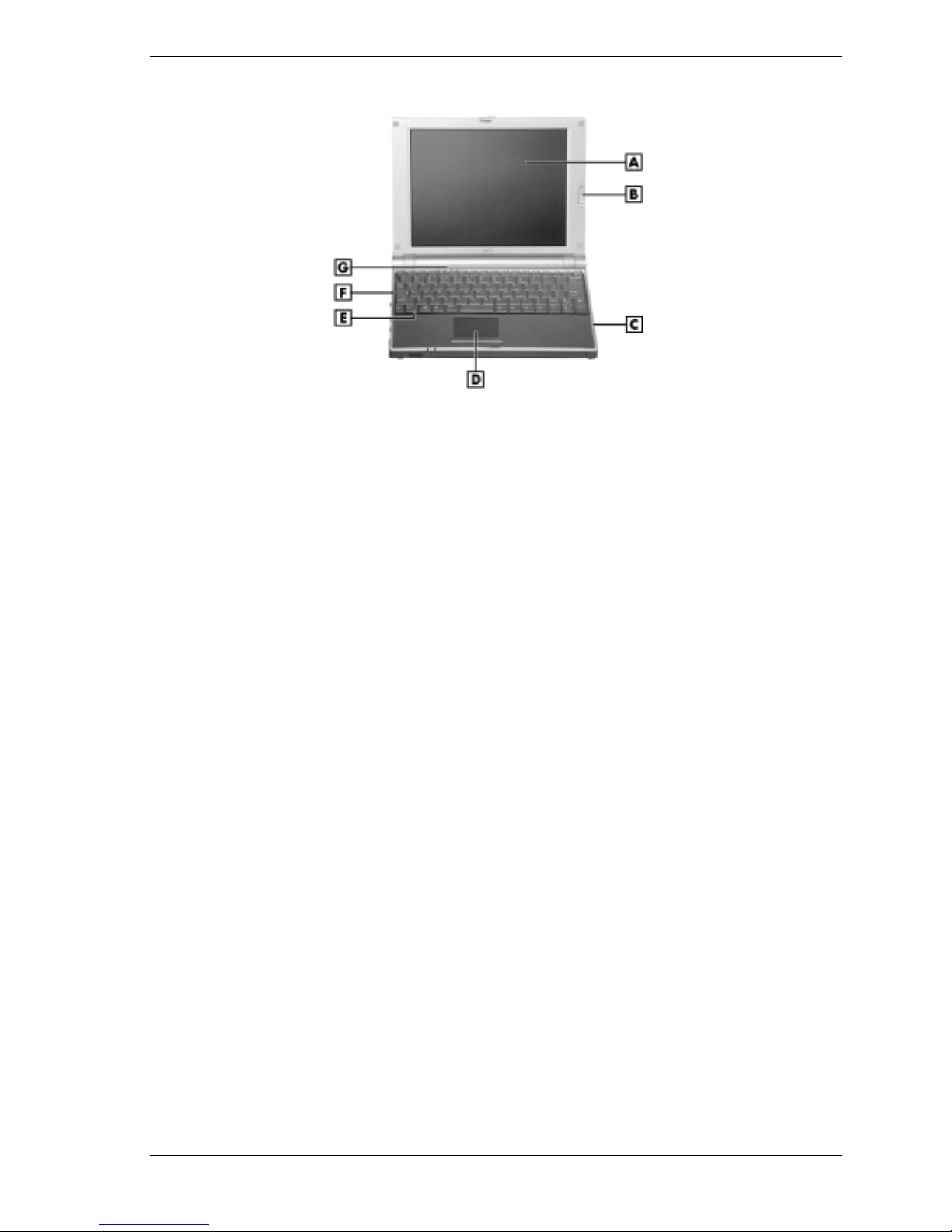
LCD Panel and Base Unit
The LCD panel and base unit features are shown in the following figures. Feature descriptions
are provided after the figures.
NEC Versa UltraLite backlit notebook/DayLite reflective notebook
A – Operating Status LEDs D – NEC VersaGlide Touchpad
B – LCD Panel E – Speaker
C – Microphone F – Keyboard
1-2 System Overview
Page 11
NEC Versa DayLite transflective notebook
A – LCD Panel E – Speaker
B – LCD Backlight On/Off Switch F – Keyboard
C – Microphone G – Operating Status LEDs
D – NEC VersaGlide Touchpad
!
LCD Panel — Provides a high-resolution display for sharp visuals on the notebook.
— Adjust the LCD panel by tilting it up or down.
— Adjust the LCD panel brightness by pressing the
!
LCD Panel Backlight On/Off Switch (NEC Versa DayLite transflective notebook only)
Fn-F8
and
Fn-F9
functions keys.
— Provides backlighting to the reflective LCD panel.
— Switch up position is on, down position is off.
!
Microphone — Allows recording of monophonic sound directly into the notebook hard
drive.
!
NEC VersaGlide Touchpad — Move a fingertip over the VersaGlide Touchpad to control
the position of the mouse pointer. Use the selection buttons below the VersaGlide Touchpad
to select menu items.
!
Speaker — Provides mono sound for the notebook when speakers are not plugged into the
speaker jack.
!
Keyboard — 86 keys with a country-specific QWERTY-key layout.
!
Operating Status LEDs — Informs user of the notebook's current operating status. See the
following figure and list for each icon's meaning.
System Overview 1-3
Page 12
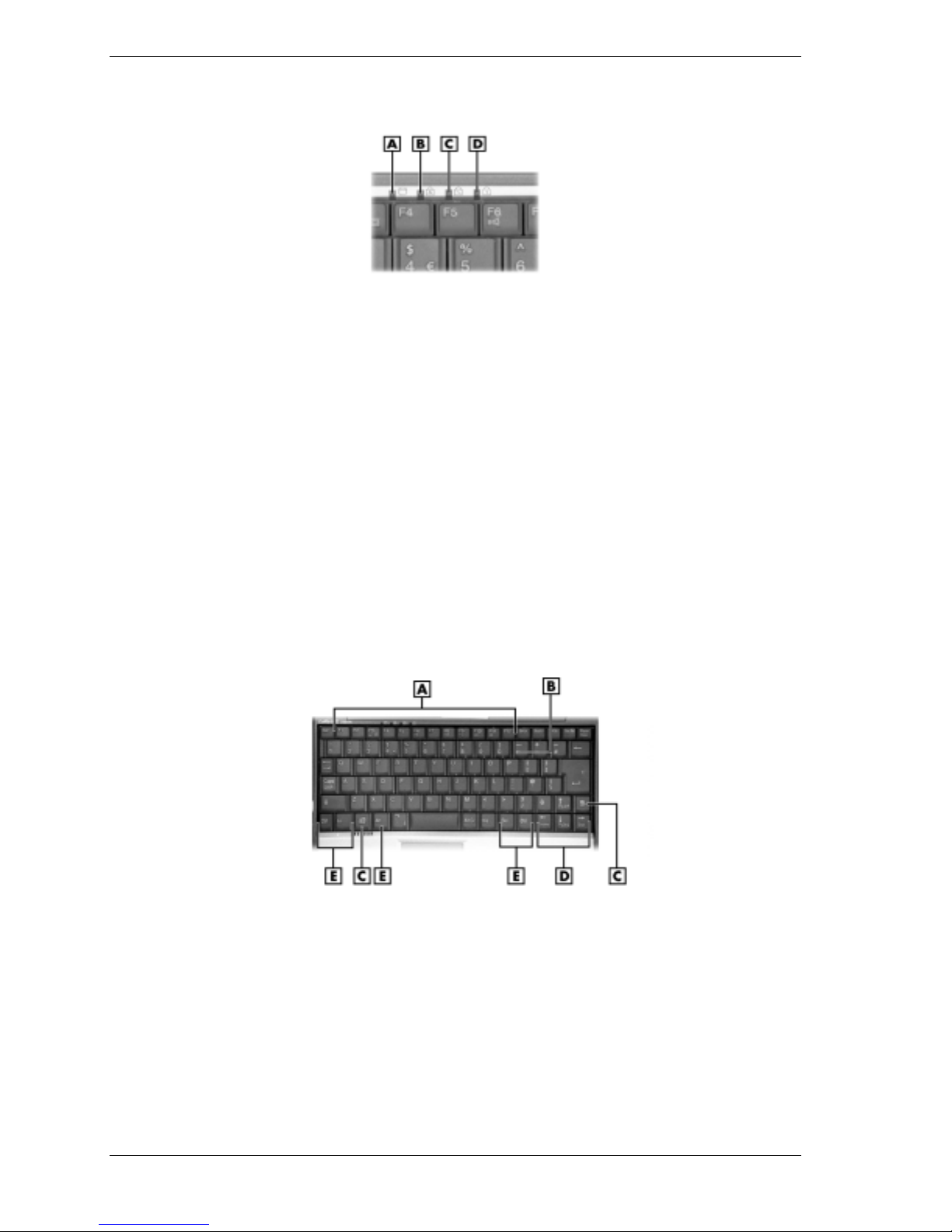
Operating status LEDs
Keyboard
A
– Hard Drive
B
– Caps Lock
C
– Scroll Lock
D
– Num Lock
— Hard Drive — lights when the notebook writes data to or retrieves data from the
internal hard drive.
— Caps Lock — lights when Caps Lock is on.
— Scroll Lock — lights when Scroll Lock is on.
— Num Lock — lights when Num Lock in on.
The keyboard features are shown in the following figure. Feature descriptions are provided after
the figure.
Keyboard
A
– Function Keys
B
– Numeric Keys
C – Windows keys
!
Function keys — Twelve function keys, F1 through
These keys work together with the
preprogrammed with dual functions and some are printed in blue on the key.
Function keys are application-driven. See the specific application's user guide for
information about how each function key works within the application you are using.
1-4 System Overview
D
– Cursor Control Keys
E
– Control Keys
F12
, are available on the keyboard.
Fn
key to activate special functions. Several keys are
Page 13
The following function key combinations are preprogrammed.
Fn-F3
— toggles between three video modes: LCD, CRT, or both (LCD and CRT).
Fn-F6
— sets the beeper volume to low, medium, high, or mute.
Fn-F8
— increases the LCD panel brightness.
Fn-F9
— decreases the LCD panel brightness.
Fn-F10
— increases the system speaker volume.
Fn-F11
— decreases the system speaker volume.
Fn-F12
— toggles the scroll lock feature.
Fn-Ins
—print screen.
Fn-Del
— system request.
Fn-Pause
— break.
Fn-↑↑↑↑ — page up.
Fn-↓↓↓↓ — page down.
Fn-←←←← — end.
Fn-→→→→ — home.
!
Numeric keypad — Pressing NumLk on the keyboard activates the numeric keypad
numbers and functions printed in blue on the keys.
The keypad lets you type numbers and mathematical operands (+, -) as you would on a
calculator. The keypad is ideal for entering long lists of numbers.
When you press NumLk again, the keys revert to their normal functions as typewriter keys.
!
Cursor Control keys — Cursor control keys let you position the cursor on the screen where
you want. On the screen, the cursor is a blinking underline, block, or vertical line depending
on the application. The cursor indicates where the next text typed is inserted.
!
Windows keys — In Windows use the following two keys to facilitate the work.
Quick access to shortcut menus
!
Control keys —
change their functions. To use control keys, press and hold the control key while pressing
another key. For example, “press
c. How the key combination works depends on the application you are running.
!
Typewriter keys — The typewriter keys (also called alphanumeric keys) are used to enter
text and characters. Keys with blue printing on them behave differently when combined
with control keys or the
Displays the Start menu
Ctrl, Alt, Fn
Fn
, and
key.
Shift
are controls used in conjunction with other keys to
Ctrl c
” means to hold down the
Ctrl
key and type the letter
System Overview 1-5
Page 14
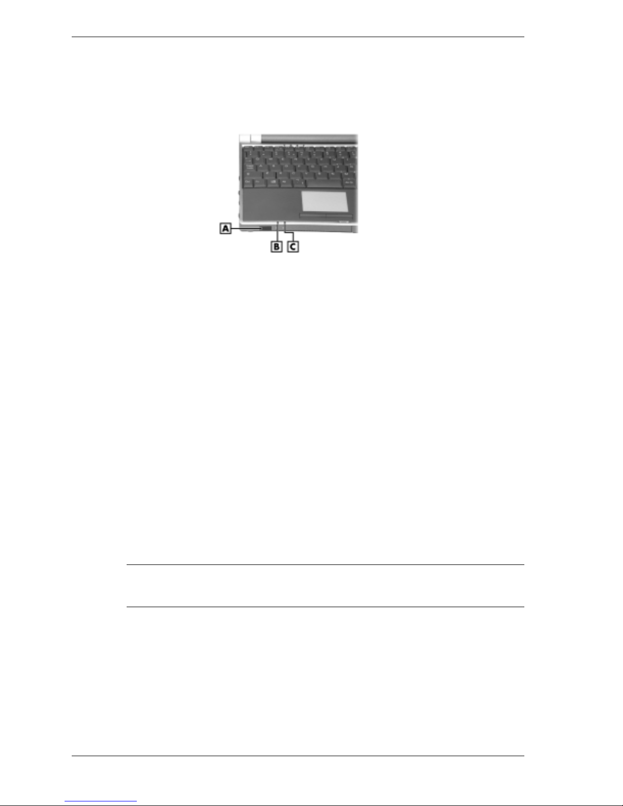
Front Features
The front features are shown in the following figure. Feature descriptions follow the figure.
Front features
A
– IR Port
B
– Battery Charging LED
!
Power Status LED — This LED lights to indicate the following:
C
– Power Status LED
— Lights green when the system power is on.
— Blinks green when the system is in Standby mode.
— Lights yellow (blinks when in Standby mode) to indicate that battery power is at 8%
capacity or less.
— Lights amber (blinks when in Standby mode) to indicate that battery power is at 3%
capacity or less.
!
Battery Charging LED — lights to indicate battery charging activity.
— Lights amber when the primary battery is charging. Blinks amber to indicate an error.
The primary battery is installed in the battery bay.
— Lights green when the secondary battery is charging. Blinks green to indicate an error.
The secondary battery is connected to the back of the system.
!
IR Port — Use this infrared (IR) port to transfer files between the NEC Versa notebook and
an IR-equipped desktop or notebook computer or to print to an IR-capable printer.
Note
enable the IR port, see Chapter 6, “Communicating with The NEC Versa” in the user’s guide that
ships with the system.
The NEC Versa ships with the IR port disabled. For detailed instructions on how to
1-6 System Overview
Page 15
Back Features
The system's secondary lithium-ion (Li-Ion) battery or an optional Extra Life Li-Ion battery can
be installed in the battery bay at the back of the notebook.
Left Side Features
The left side features are shown in the following figure. Feature descriptions follow the figure.
A – AC Power Port D – RJ-11 Jack
B – Vent E – USB Port
C – External Monitor (Video) Port F – LAN Cable Jack
!
AC Power Port — Attaches the notebook to a power source, such as the AC adapter.
!
Vent — Allows the system to cool properly and maintain a safe operating temperature.
Left-side features
!
External Monitor (Video) Port — Use this port to attach an external monitor to the
notebook. The LCD display and external monitor can be run simultaneously or run alone.
!
RJ-11 Jack — Connects the internal modem to an analog telephone line.
!
USB Port — The Universal Serial Bus (USB) port allows connection of up to 127 USBequipped peripheral devices (printers, monitors, scanners, etc.).
!
LAN Cable Jack (optional) — If the system has this feature, the system ships with a local
area network (LAN) adapter cable to connect the jack to a LAN.
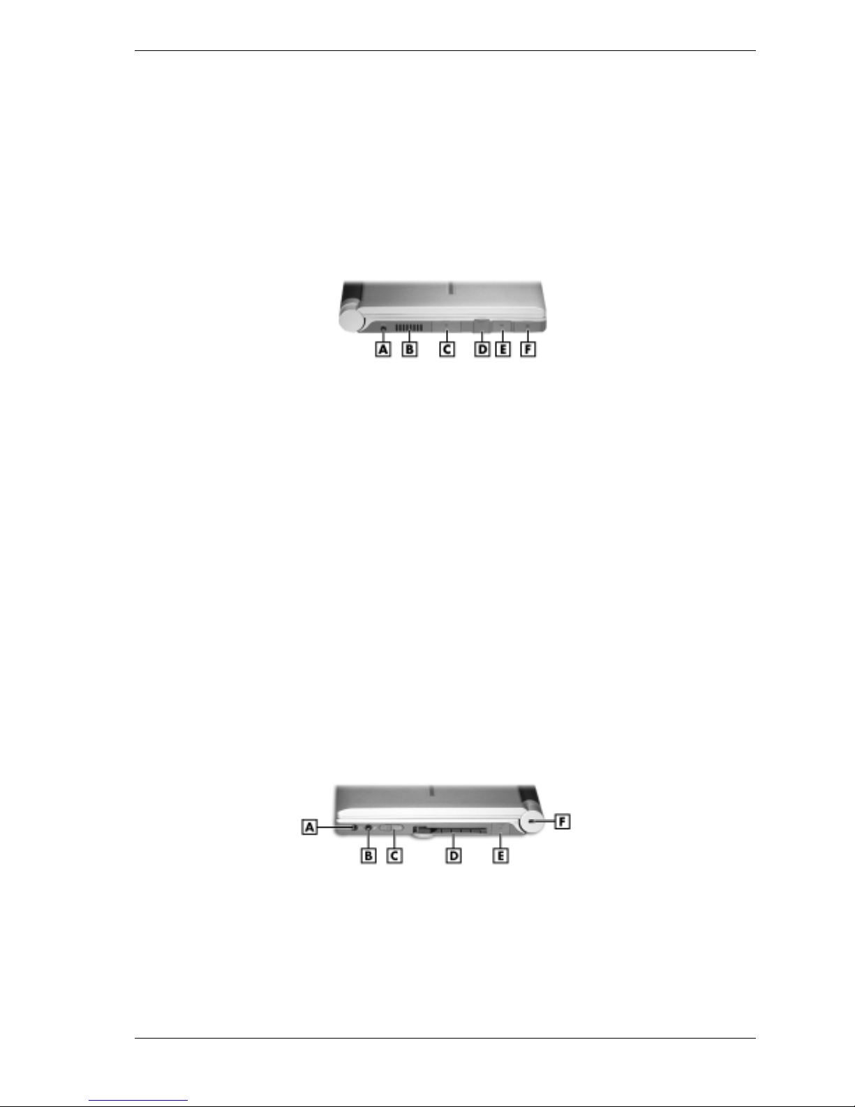
Right Side Features
The right side features are shown in the following figure. Feature descriptions follow the figure.
A – Headphone Jack/External Speakers D – PC Card Slot
B – External Microphone Jack E – USB Port
C – Power Button F – Kensington
Right-side features
®
Lock Slot
!
Headphone Jack/External Speakers — Connect an external headphone set or speakers to
this jack. Plugging in headphones disables the built-in system speakers.
System Overview 1-7
Page 16
!
!
!
!
!
Power Button
The Power button is a “smart” switch and recognizes when the notebook is in Standby mode. If
in Standby mode, the Power button must be slid to the right to resume operation. (The BIOS
parameter “System Switch” must be set to “Sleep.”)
Put the unit in Standby mode when it’s necessary to be away from the system for a short period
of time and want to return to where you left off. Standby mode shuts down all devices in the
system while retaining data and system status. Go to Start, Shut Down, Standby to put the
system into Standby mode.
Use the Power button in the following ways:
External Microphone (MIC) Jack — Connect an external microphone to this jack. Plugging
in an external microphone disables the built-in microphone.
Power Button — Slide the Power button forward to power on, power off, and to resume
from Standby mode. For more information, see “Power Button” in the following section.
PC Card Slot — Accommodates one type II PC Card. These cards are often storage or
communication devices such as Static Random Access Memory (SRAM), Read Only
Memory (ROM), Flash Memory, LAN, and Small Computer System Interface (SCSI).
USB Port — The Universal Serial Bus (USB) port allows connection of up to 127 USBequipped peripheral devices (printers, monitors, scanners, etc.).
Kensington Lock Slot — Provides a connection for an optional Kensington Lock.
— Slide the Power button forward to power on.
— Slide the Power button forward to resume from Standby mode and proceed with normal
operation.
— Hold the Power button in place for four or more seconds to power off the system
(power override). Only use this option if you cannot power off the system using Start,
Shut Down.
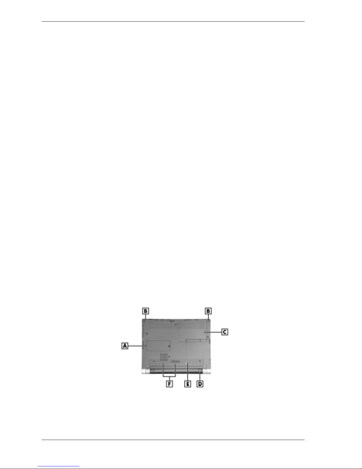
Bottom Features
The bottom features are shown in the following figure. Feature descriptions follow the figure.
Bottom features
A – Memory Module Bay D – Secondary Li-Ion Battery
B – Notebook Feet (2 of 5) E – Battery Release Latch
C – Hard Drive Bay F – Vents
!
Memory Module Bay — Holds an optional memory module.
1-8 System Overview
Page 17

!
Notebook Feet — Opens space under the notebook for proper ventilation.
!
Hard Drive Bay — Holds the notebook’s hard drive.
!
Secondary Li-Ion Battery — Removable secondary power supply.
!
Battery Bay Release Latch — Releases and removes the notebook’s secondary battery.
!
Vents — Allow the notebook to cool properly and maintain a safe operating temperature.
Component Features
The following sections contain brief descriptions of the notebook’s internal hardware.
Primary Battery
Each notebook is equipped with a rechargeable, non-replaceable, primary Lithium Polymer
(Li-Poly) battery. The NEC UltraLite notebook uses a 12-cell battery. The NEC DayLite SVGA
reflective notebook uses a 12-cell battery. The NEC DayLite XGA transflective notebook uses a
9-cell battery. The primary battery is built into the back of the LCD panel.
Secondary Battery
Always keep the vents unobstructed for proper system cooling.
A removable secondary Li-Ion 3-cell battery is installed in the battery bay to help prevent data
loss. An optional Extra Life Li-Ion battery can be installed in the battery bay in place of the
standard secondary battery.
CMOS Battery
The lithium CMOS battery on the main board provides battery backup and prevents data loss in
the system's complementary metal oxide semiconductor (CMOS) RAM. This memory area
contains information on the system's configuration, for example date, time, drives, and memory.
The CMOS battery charges when the notebook is connected to AC power. The CMOS battery
may discharge completely if the notebook remains unused for approximately two months.
Hard Drive
A standard 2.5-inch, 9.5 mm hard drive ships with the system.
System Overview 1-9
Page 18

Chipset Features
The following table provides information on the chipset.
Chip Manufacturer Description
TransMeta TM5600 Crusoe TransMeta 600 MHz CPU
82440MX Intel System Controller
FDC37N869 Standard Microsystems Super I/O
SM721 Silicon Motion Video
EV1938 Creative Technology Audio
29F004TC-90 ROM BIOS
M38813M4 Mitsubishi Keyboard Controller
TI PCI 1420 Texas Instruments PCI CardBus Controller
System Chipset
1-10 System Overview
Page 19

System Configuration and Setup
!
Power Sources
!
BIOS Setup
!
Updating the BIOS
!
Transmeta LongRun Utility
!
NEC Customize Utility
!
Application and Driver CD
!
Product Recovery CD
2
Page 20

Power Sources
The notebook can be powered using one of the following sources:
!
AC adapter connected to an electrical wall outlet [alternating power (AC) power]
!
primary battery and secondary battery
!
optional Auto adapter (for use, see the accessory sheet that ships with the option).
The following sections include specific information about using the power sources.
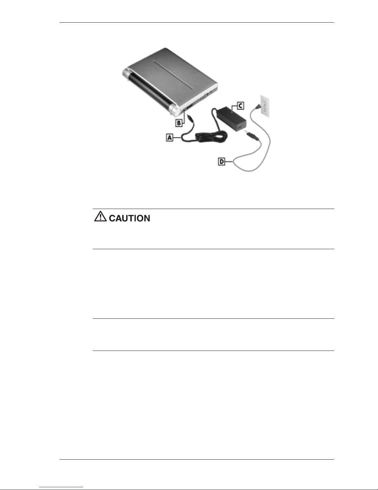
AC Adapter
Use the AC adapter and power cable that came with the notebook to run it on AC power, or to
recharge the primary and secondary batteries. Use the AC adapter whenever a wall outlet is
nearby.
Keep the adapter connected whenever possible. The AC adapter charges the battery when it is
connected, whether the notebook is powered on or off.
AC adapter
A – AC Adapter C – Power Cable
B – Adapter Cable
replaceable or serviceable parts inside. Dangerous voltage in the AC adapter can cause serious
personal injury or death. The AC adapter is intended for use with a notebook computer and must
meet EN609050 standards.
Connecting the AC Adapter
Note
being used. Contact the local dealer to purchase the correct power cable.
Connect the AC adapter as follows:
1.
2.
The AC power cable type that the system uses depends on the country where it is
Connect the AC adapter cable to the power port on the left side of the notebook.
Plug one end of the AC power cable into the AC adapter and the other end into a properly
grounded 120- or 240-volt, 50- or 60-Hz wall outlet.
Do not disassemble the AC adapter. The AC adapter has no
2-2 System Configuration and Setup
Page 21
Connecting the AC adapter
A – Adapter Cable C – AC Adapter
B – AC Power Port D – Power Cable
clear of objects lets the adapter cool properly during use.
Only use the AC adapter that comes with the NEC Versa notebook. Although other adapters look
similar, using them can damage the system.
Powering on the System
Power on the system as follows:
1.
Locate the latch on the front of the notebook, slide it to the right, and raise the LCD panel.
2.
Locate the Power button and slide it forward to turn on power. For additional information
about power buttons and LEDs, see Section 1, “System Overview.”
Note
system, you might encounter a warning message suggesting that a problem exists with the
hibernation file. The warning message is inaccurate. To disable this message, simply enable
hibernate support.
When powering on the notebook running the Microsoft Windows 2000 operating
Do not cover or place objects on the AC adapter. Keeping the adapter
System Configuration and Setup 2-3
Page 22

Batteries
The notebook comes with a rechargeable Lithium Polymer primary battery, a rechargeable
Li-Ion secondary battery, and a rechargeable CMOS battery. In addition, an optional Li-Ion
battery can be purchased as a backup battery.
The primary battery is installed behind the LCD panel and is not replaceable. The secondary
battery is installed in the battery bay and is replaceable. The CMOS battery is installed on the
main board and is replaceable (see Section 3, “Disassembly and Reassembly,” for CMOS
battery replacement).
The following sections include information for extending battery life, determining battery status,
and handling the secondary battery.
Extending Battery Life
The following tips can help ensure the longest possible battery run time for the primary and
secondary batteries.
!
Change the display color depth setting from 16-million colors to 64K colors. This change is
not detectable in non-graphics applications, and uses less power. The system default setting
is 16M colors.
!
Install the LongRun™ utility, which is described in more detail later in this document. You
can use the LongRun utility to force the processor to run at a slower speed, extending
battery run time.
!
Note that add-in PC Cards increase battery usage, reducing battery run time.
!
Keep the notebook fully charged when working near available AC power.
!
Use the
Fn-F8
and
extend battery life.
!
Disable the IR device port if not using it.
Determining Battery Status
Notebook tools help keep track of the primary and secondary battery power levels. If the
notebook is configured to display the power icon on the taskbar (default setting), an electrical
plug appears when it is connected to an AC power source or a battery icon appears when it is not
connected to an AC power source.
Use the power meter to determine battery status. Access the power meter in the following ways:
!
Move the cursor over the Power icon on the taskbar to display the remaining battery power
for the primary battery.
!
Right click the Power icon on the taskbar to open the power meter or to adjust power
properties.
!
Double click the Power icon on the taskbar to display the remaining power for both the
primary battery and the secondary battery.
!
On the Windows desktop, point to
Management
. Select the Power Meter tab.
Fn-F9
function keys to control brightness. Lowering brightness can
Start, Settings, Control Panel
, and double click
Power
2-4 System Configuration and Setup
Page 23

Low Battery Status
When battery power is
!
low (8% or less), the power LED lights yellow when in use, and flashes yellow in standby.
!
very low (3% or less) the power LED lights amber when in use, and flashes yellow in
standby.
When the notebook is in a low battery status, do one of the following:
!
Power off the notebook, remove the secondary battery, and replace it with a fully charged
battery.
!
Leave the secondary battery in the notebook and charge the battery. (See “Charging the
Battery” in the following section. Also see the appropriate user’s guide for specifics on
charging times.)
Charging the Battery
Adhere to the following precautions when recharging the battery (also see “Secondary Battery
Precautions” later in this section).
!
Charge the battery for the specified charge time only.
!
During charging, keep the environmental temperature between 32° F and 104° F
(0° C to 40° C).
Charge the primary and secondary batteries by connecting the notebook to an AC power source.
It takes approximately 8 hours to fully charge the battery while the notebook is on, and 4.5 hours
while off. To monitor the charging activity, observe the battery charging LED on the front of the
notebook. The battery charging LED lights as follows:
!
Lights amber when the primary battery is charging.
!
Blinks amber if the primary battery encounters an error while charging.
!
Lights green when the secondary battery is charging.
!
Blinks green if the secondary battery encounters an error while charging.
Secondary Battery Handling
Keep the following in mind when removing or replacing the secondary battery (the primary
battery is not replaceable).
!
Use only the NEC Versa notebook battery designed for the notebook. Using other
manufacturers’ batteries or using very old batteries can deteriorate battery and equipment
performance.
!
Turn off power to the notebook after use. Keeping power on can degrade battery
performance and shorten battery life.
!
Clean the battery connectors with a dry cloth when they get dirty.
!
Keep the battery out of the reach of children.
System Configuration and Setup 2-5
Page 24

Precautions
To prevent accidental secondary battery ignition, rupture, or explosion, adhere to the following
precautions.
replaced. Replace only with the same or equivalent type recommended by the
manufacturer. Discard used batteries according to the manufacturer’s instructions.
To avoid personal injury and property damage, read these battery precautions on handling,
charging, and disposing of Li-Ion batteries.
!
!
!
!
!
!
!
!
If the battery leaks:
!
!
!
There is a danger of explosion if the battery is incorrectly
Keep the battery away from heat sources including direct sunlight, open fires,
microwave ovens, and high-voltage containers. Temperatures over 140º F (60º C) may
cause damage.
Do not drop or strike the battery.
Do not disassemble the battery.
Do not solder the battery.
Do not puncture the battery.
Do not use a battery that appears damaged or deformed, has any rust on its casing, is
discolored, overheats, or emits a foul odor.
Keep the battery dry and away from water.
Keep metal objects away from battery connectors. Metal objects in contact with the
connectors can cause a short circuit and damage.
If the battery leaks onto skin or clothing, wash the area immediately with clean water.
Battery fluid can cause a skin rash and damage fabric.
If battery fluid gets into eyes, DO NOT rub; rinse with clear water immediately and
consult a doctor.
Take extra precautions to keep a leaking battery away from fire. There is danger of
ignition or explosion.
Replacing the Secondary Battery
Replace the secondary battery (or optional Extra Life battery) when it displays the following
end-of-life symptoms:
!
shorter work times
!
discoloration, warping
!
hot to the touch
!
strange odor.
Replace the secondary battery as follows.
1.
Save the files, exit the Windows operating system, and turn off notebook power.
2.
Close the LCD panel and turn over the notebook.
3.
Slide the battery release latch toward the right side of the notebook and hold firmly.
2-6 System Configuration and Setup
Page 25
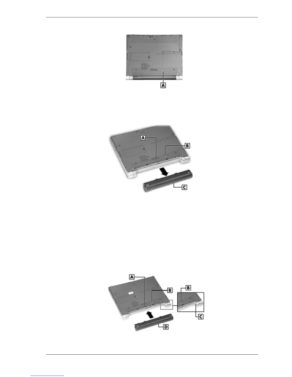
Locating the battery bay release latch
A – Battery Release Latch
4.
While holding the battery release latch to the right, slide the battery out of the notebook.
Removing the secondary battery
A – Battery Bay Connectors C – Secondary Li-Ion Battery
B – Battery Bay Release Latch
5.
Install the new secondary (or optional Extra Life) battery as follows:
! Locate the alignment grooves on the edge of the battery and inside the battery bay (see
the following figure).
! Align the grooves on the battery with the grooves in the bay.
! Slide the battery into the bay until it is securely locked in place.
6.
Turn over the notebook.
Installing the secondary battery
A – Battery Bay Connectors C – Alignment Grooves
B – Battery Bay Release Latch D – Secondary Li-Ion Battery
System Configuration and Setup 2-7
Page 26

BIOS Setup
The notebook comes with a BIOS Setup Utility that allows parameter viewing and setting. BIOS
Setup also allows setting password features that protect the system from unauthorized use.
Use BIOS Setup to:
!
set the current time and date
!
customize the operating system to reflect the computer hardware
!
secure the system with a password
!
balance the performance needs with power conservation.
Access the BIOS utility at power-on by pressing
Press <F2> to Enter Setup.
When you press F2 to enter BIOS Setup, the system interrupts the Power-On Self-Test (POST)
and displays the current CMOS RAM settings.
If the system detects an error during POST, it prompts you with a double beep and a message:
“Press <F1> to resume.” If you press
want to fix the error, carefully read the error message that appears above the prompt (taking
notes if you want), and press
discharged.
F2
when the following prompt appears.
F1
, the system enters BIOS Setup automatically. If you
F2
. You will see this message if the CMOS battery becomes fully
BIOS Setup Main Menu
After pressing F2, the system displays the BIOS Setup Main Menu window. The bar at the top
of the Main Menu window lists the following top-level menus.
!
Main Use the Main menu for basic system configuration. For example, select Main to set
the system time and date, set diskette and hard disk parameters, or check memory
parameters.
!
Advanced Use the Advanced menu to set IR serial port, I/O device configuration, LCD
panel view, and more.
!
Security Use this menu to set User and Supervisor passwords, password on boot, fixed
disk boot sector.
!
Boot — Use this menu to set boot sequence.
!
Exit Exits the Setup utility with various save or discard options.
Use the keys listed in the legend bar on the bottom of the Setup menu to make the selections or
exit the current menu. The following table describes the legend keys.
2-8 System Configuration and Setup
Page 27

Setup Key Functions
Key Function
F1 Provides help for the parameter field being displayed.
Esc Exits the menu.
Up or down arrow keys Moves cursor up and down for item selection.
Left or right arrow keys Selects next menu.
F5/F6 Changes values.
Enter Executes a command or selects submenu.
F9 Loads the default configuration values for the current menu.
F10 Saves the current values and exits Setup.
To select one of the five menus from the menu bar, use the left and right arrow keys. Use the up
or down arrow keys to select an item under the menu.
Menu items preceded by a > contain a submenu of selectable fields for setting system
parameters. Display a submenu by using the up or down arrow keys to move the cursor to the
desired submenu, then press
An Item Specific Help window on the right side of each menu displays the help text for the
currently selected Setup option. It updates as the cursor moves to each new field.
Enter
.
Pressing
their functions.
Press
The following subsections describe the five top-level menus and their submenus.
Note
may differ, depending on the notebook model and the hardware installed in the notebook.
Main Menu
Choose the Main menu by selecting Main in the legend bar on the Main menu screen. Other
Main menu options are available by selecting submenus.
Use the arrow keys to select one of the Main menu options and press
Items with grayed-out text are not available. Explanations of each Main menu item are in the
following table.
F1
on any menu brings up the General Help window that describes the legend keys and
Esc
to exit the current window.
The following menu information is typical. The actual settings on the menu screens
Enter
to select a submenu.
System Configuration and Setup 2-9
Page 28

Setting items on this menu to incorrect values can cause notebook
malfunctions.
Main Menu Items
Menu Item Settings (default is bold)
System Time
System Date
Language
Diskette A
Internal HDD
Set system time in this field. Press Tab or Enter to move
between hour, minute, and second fields.
Example: 09:30:00
Set system date in this field. Press Tab or Enter to move
between month, date, and year fields.
Example: 07/09/2001
English, Japanese
Selects the display language for the BIOS. Bring up the
Language submenus by pressing
Disabled,
Selects the diskette drive type. Bring up the Diskette A
submenu by pressing Enter.
Displays the HDD capacity.
Example: xxxxx MB
Bring up the Internal HDD submenu by pressing Enter.
The submenus include Type and LBA Format.
See the table, “Internal HDD Menu Items” for descriptions
of each submenu and its fields.
1.44
Enter
.
LCD
Boot Display Device
System Memory Displays amount of conventional memory detected during
Extended Memory Displays amount of extended memory detected during
CPU Type Displays the processor type.
Both,
Allows you to choose either display devices, or both.
boot.
This field is read-only and cannot be changed from BIOS
Setup.
Example: 640 KB
boot.
This field is read-only and cannot be changed from BIOS
Setup.
Example: xxxxx KB
This field is read-only and cannot be changed from BIOS
Setup.
, CRT
2-10 System Configuration and Setup
Page 29

Main Menu Items
Menu Item Settings (default is bold)
CPU Speed Displays the processor speed.
This field is read-only and cannot be changed from BIOS
Setup.
Example: 600 MHz
BIOS Revision Displays the BIOS revision number.
This field is read-only and cannot be changed from the
BIOS Setup.
Example: 1.0F-3707-6211/149A-0100
QuickBoot Mode
Enabled, Disabled
Internal HDD Submenu Items
Menu Item Settings (default is bold)
Type
Cylinders When Type is Auto, value in the Cylinders field is auto-
Heads When Type is Auto, value in Heads field is auto-detected
Auto, None, User
When set to Auto, the values for Cylinders, Heads,
Sectors, and Maximum Capacity as read only.
When set to Auto, the BIOS detects what the drive is
capable of, not the translation mechanism that was used to
format the drive. If a drive is run in a mode other than the
mode in which it was partitioned and formatted,
unpredictable results may occur, including data loss.
When set to None, informs the system to ignore this drive.
When set to User, allows the manual entry of all fields
described next.
detected and field is read only.
and field is read only.
Sectors When Type is Auto, value in Sectors field is auto-detected
Maximum Capacity This field is read-only and cannot be changed from BIOS
Multi-Sector Transfers
and field is read only.
Setup.
Example: xxxxx MB
Disabled, 2, 4, 8, 16 sectors
Determines the number of sectors per block for multi-sector
transfers.
When Type is Auto, value in Multi-Sector Transfers field is
auto-detected and field is read only.
System Configuration and Setup 2-11
Page 30

Internal HDD Submenu Items
Menu Item Settings (default is bold)
LBA Mode Control
32-Bit I/O
Transfer Mode Standard, Fast PIO1, Fast PIO2, Fast PIO3, Fast PIO4,
Ultra DMA Mode
Enabled, Disabled
When Enabled is selected, it causes logical block
addressing to be used in place of cylinders, heads, and
sectors.
When Type is set to Auto, the value in the LBA Mode field
is auto-detected and the field is read only.
Disabled,
When Enabled, allows 32 bit data transfers.
Fast PIO3/DMA1, Fast PIO4/DMA2
Selects the method for moving data to and from the drive.
When Type is set to Auto, the value in the field is autodetected and the field is read only.
Disabled, Mode 0, Mode 1, Mode 2, Mode 3, Mode 4
Selects the Ultra DMA Mode for moving data to and from
the drive. Autotype the drive to select the optimum transfer
mode.
When Type is set to Auto, the value in the field is autodetected and the field is read only.
Enabled
Advanced Menu
Choose the Advanced menu by selecting Advanced in the legend bar on the Main menu screen.
Other Advanced menu options are available by selecting submenus.
Use the arrow keys to select one of the Advanced menu options and press
submenu. Items with grayed-out text are not available. Explanations of each Advanced menu
item are in the following table.
malfunction.
Menu Item Settings (default is bold)
BootUp Num-Lock
PS/2 Mouse
Enter
to select a
Setting items on this menu to incorrect values can cause the system to
Advanced Menu
LockOn,
Selects the state for Num Lock at power on.
Enabled, Disabled
Enabled forces the PS/2 mouse port to be enabled
regardless of whether a mouse is present. Disabled
prevents any installed PS/2 mouse from functioning, but
frees up IRQ 12.
LockOff
2-12 System Configuration and Setup
Page 31

Advanced Menu
Menu Item Settings (default is bold)
LCD Panel View Expansion
BootUp Message
Summary Screen Disabled, Enabled.
Silent Boot
I/O Device Configuration
On Board Device Configuration
USB Device
Enabled, Disabled
Disabled reduces the panel view in some video modes.
Enabled expands the panel view. The enabled setting
sometimes affects graphic quality.
Enabled, Disabled
Disabled suppresses the logo screen during boot.
When set to Enabled, information about the system’s
configuration is displayed onscreen during boot.
Disabled, Enabled, Black
When set to Enabled, the logo screen appears during
boot. Disabled causes the POST messages to appear
during boot. Black causes the screen to remain black
during boot.
Press Enter to bring up the I/O Device Configuration
submenu to configure the IR serial port.
Press Enter to view submenu.
Enable, Disable
Security Menu
Choose the Security menu by selecting Security from the Main menu screen. Other Security
menu options are available by selecting submenus.
Use the arrow keys to select one of the Security menu options and press
submenu. Items with grayed-out text are not available. Explanations of each Security menu item
are in the following table.
Menu Item Settings (default is bold)
Set Supervisor Password
Set User Password
Enter
to select a
Security Menu Items
Press Enter to access.
Use this field to set or change the supervisor password.
Press Enter to bring up a dialog box where the password
can be entered and confirmed.
Press Enter to access.
Use this field to set or change the user password. Press
Enter to bring up a dialog box where the password can be
entered and confirmed.
System Configuration and Setup 2-13
Page 32

Security Menu Items
Menu Item Settings (default is bold)
Boot Menu
Password on Boot
Fixed Disk Boot Sector
Disabled, Enabled
When Enabled, requires password entry before boot.
System remains in secure mode until the password is
entered.
Normal
Write Protect protects the boot sector on the hard disk
from viruses.
, Write Protect
Choose the Boot menu by selecting Boot in the legend bar on the Main menu screen. Other Boot
menu options are available by selecting submenus.
Use the arrow keys to select one of the Boot menu options and press
Enter
to select a submenu.
Items with grayed-out text are not available. Explanations of each Boot menu item are in the
following table.
Boot Menu Settings
Menu Item Settings (default is bold)
USB Drive
Hard Drive
The Boot Menu displays the bootable devices in the
current boot order.
Exit Menu
Use the up or down arrows to select a device.
Press Enter to expand or collapse device information.
Press Ctrl Enter to expand or collapse all device
information.
Use the plus (+) or minus (-) key to move a selected
device up or down in the boot order.
Choose the Exit menu by selecting Exit in the legend bar on the Main menu screen. Other Exit
menu options are available by selecting submenus.
Use the arrow keys to select one of the Exit menu options and press
Enter
. Explanations of each
Exit menu item are in the following table.
Exit Menu Items
Menu Item Settings (default is bold)
Exit Saving Changes Implements the changes just made, and exits BIOS.
Exit Discarding Changes Exits, leaving BIOS unchanged.
Load Setup Defaults Loads default values for all BIOS setup fields.
2-14 System Configuration and Setup
Page 33

Menu Item Settings (default is bold)
Discard Changes Loads previous values from BIOS for all setup fields.
Save Changes Saves all setup value changes to BIOS.
Battery Refresh Reactivates the battery (applies to the Li-Ion battery).
Updating the BIOS
The BIOS only needs updating if NEC Computers makes significant improvements or fixes to
the current system BIOS. Call NEC Computers Support Services to determine if the BIOS needs
updating and for assistance in updating the BIOS (see Section 8, “Getting Service and Support”
for contact information).
If the BIOS needs updating, use the procedures in the following sections. Be sure to use the
BIOS Update Diskette for the specific NEC Versa notebook model.
To update the BIOS you must:
!
obtain the BIOS Update
!
prepare the BIOS Update Diskette
!
enable the BIOS Flash DIP Switch
!
perform the BIOS Update
Exit Menu Items
!
disable the BIOS Flash Setting.
Obtaining the BIOS Update
Contact NEC Computers Support Services to obtain the BIOS Update Diskette. Or you can
download the BIOS update from the NEC Computers web site (see Section 8 for web site
information). Download the BIOS Update onto a diskette.
Preparing the BIOS Update Diskette
Once the BIOS Update Diskette is available (either from NEC Computers or downloaded), you
must make it BIOS flash ready. See the readme.txt file on the diskette before using the diskette.
Use these steps to prepare the BIOS Update Diskette.
1.
Scan the hard drive for viruses.
2.
Enable the diskette for write access.
3.
Insert the diskette into the external diskette drive.
4.
Type a:install at the DOS prompt and follow the prompts.
5.
Install.bat copies the DOS system files from the hard drive onto the BIOS Update Diskette
to make it BIOS flash ready.
6.
The system prompts you when the process is complete.
7.
Scan the BIOS Update Diskette for viruses.
8.
The BIOS Update Diskette is ready for use.
9.
Set the BIOS Flash switch (DIP switch 5) to OFF (see “Setting the DIP Switch,” later in this
section).
System Configuration and Setup 2-15
Page 34

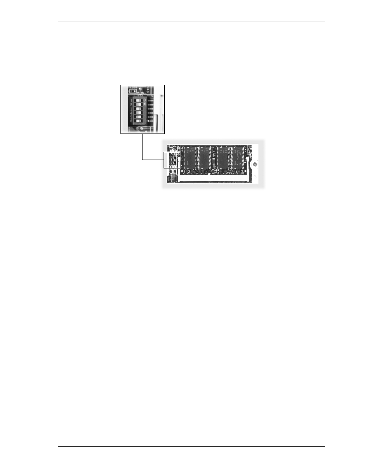
Setting the DIP Switch
Several system settings, including BIOS Flash, are set through a six-position DIP switch located
on the bottom of the notebook, under the memory bay cover. The following list identifies each
switch, its default setting, and its function. Procedures for setting the switches follow the list.
Switch 1 — Password override, default setting is OFF. If the password is forgotten, change
the switch setting to ON and the current password is erased.
Switch 2 — Keyboard select; default setting is ON for U.S. 85 key keyboard and OFF for
European keyboard.
Switch 3 — Not assigned; default setting is OFF.
Switch 4 — Keyboard select 2; default setting is ON for US and OFF for European
keyboards.
Switch 5 — Reserved for factory use; default setting is ON. Off is for BIOS Flash.
Switch 6 — Logo select; default setting is OFF.
Use these steps to access the DIP switch in the memory bay and to set a switch.
1.
Power off the system and disconnect any peripheral devices.
processor, and other system components. Before opening the system and handling system
components, attach an antistatic wrist strap to your wrist and to chassis ground (any unpainted
metal surface on the system) to avoid ESD damage.
Hold a board only by its edges. If removing a board, place it component-side up on a grounded,
static-free surface or in a static-free wrapper. If installing a new board, do not remove it from its
protective wrapper until you are ready to install it.
Electrostatic discharge (ESD) can damage hard drives, boards,
2.
Turn the system over and locate the memory bay cover and fastening screw (see the
following figure).
3.
Remove the screw and memory bay cover.
Removing the memory bay cover
A – Screw B –Memory Bay Cover
2-16 System Configuration and Setup
Page 35
4.
Check and set the DIP switch as necessary (see the following figure for switch location).
! Use a ball point pen to slide the switch to the desired setting.
! If setting for BIOS Flash, set switch 5 to its OFF position.
Default switch settings
5.
Replace the memory bay cover and screw.
6.
Turn over the notebook.
7.
Continue to “Performing the BIOS Update.”
Performing the BIOS Update
Use these steps to perform the BIOS update.
1.
Before you begin, do the following.
! Connect the notebook to AC power and power on the notebook.
! Configure the Boot Device Setup to boot from a diskette.
! Remove any bootable CDs from the CD-ROM drive, if connected.
! Document all customized BIOS settings.
2.
Power on the notebook with the BIOS Update diskette in the drive. The computer boots and
automatically loads the utility. A message similar to the following appears.
The NEC BIOS Update Utility should not be used to modify the BIOS in a Versa system
which is docked. If your Versa is docked, please exit the BIOS Update Utility, power down,
and undock your Versa before running the utility. Plug in your AC cable before restarting the
flash utility.
3. Press
Enter
The utility checks the currently installed BIOS version and the diskette’s BIOS version. The
Main Menu appears.
4.
Use the arrow keys to highlight the “Display BIOS Version” option on the Main Menu. Use
this option to check the currently installed BIOS version and the version of the new
replacement BIOS. Press any key to return to the Main Menu.
to continue.
System Configuration and Setup 2-17
Page 36

5.
Highlight the “Install New BIOS” option and press
Enter
.
6.
Press Y and press
Enter
. After a brief pause, a message appears telling you to remove the
diskette from the drive.
7.
Remove the diskette and press any key to continue. The utility updates the BIOS.
8.
Power off the notebook. The next time the notebook is powered on, you will have the latest
NEC Versa notebook BIOS.
9.
Power on the notebook. A CMOS Checksum message appears and prompts you to press
to enter Setup.
10.
Press F1 to enter Setup and restore the default parameter settings.
11.
Modify any custom settings that that may have been configured in the old BIOS. Use the
BIOS setting information that was copied before starting the BIOS upgrade.
12.
Set DIP switch 5 to “ON” after completing the BIOS update.
Transmeta LongRun Utility
The Crusoe processor that powers the notebook is equipped with the LongRun power
management utility. This utility automatically adjusts the clock speed and voltage of the
processor based on the needs of the application. If the system is in an idle state, or doing
processing that doesn’t require faster clock speeds, it automatically lowers to 300MHz. If the
system is completing more demanding tasks, it adjusts up to a full 600MHz. The ability to lower
the processor speed results in longer battery life for your notebook.
The LongRun utility allows overriding the automatic adjustments by the processor. You can
F1
! Force the processor to stay at the lower 300MHz speed to preserve the battery when
you need the notebook to run for a long time without an AC source. Forcing the battery
to run at lower speeds slows some applications but extends the battery life by hours.
! Force the processor to stay at the higher 600MHz speed when speed is necessary, or
when the notebook is running on an AC power source.
To install the LongRun utility, run the NEC Customize utility (see “NEC Customize Utility”
later in this section) and select “Install/Uninstall LongRun Utility.” Press
OK
and reboot the
notebook after the installation is completed. Click on the LongRun icon in the Windows desktop
tray to bring up the LongRun Utility status bar.
LongRun utility status bar
A – Current Speed D – Current Speed Indicator
B – Range of Speeds E – Maximum Speed Slider
C – Minimum Speed Slider
2-18 System Configuration and Setup
Page 37

To manually adjust the processor speed, use the slider bar on the LongRun utility status. To
adjust the default GUI properties of the LongRun utility, right click on the top of the LongRun
dialog title bar and select Properties from the pull-down menu.
Uninstalling the LongRun Utility
The LongRun utility can be removed and reinstalled at any time.
Before removing the utility, close the application by right clicking on the icon in the system tray
and choosing “Close LongRun.” Run the NEC Customize utility and select “Install/Uninstall
OK
LongRun Utility.” Click
and reboot the notebook after the uninstall process is completed.
Uninstalling the LongRun utility does not remove it from the hard drive. If the LongRun utility
is uninstalled, it can be reinstalled at any time through the NEC Customize Utility.
NEC Customize Utility
The NEC Customize Utility allows installation or launch of the following:
!
Application and Driver CD — to install a variety of software applications, drivers, utilities,
internet browsers, and the NEC INFO Center.
!
Transmeta LongRun Utility — to optimize battery power consumption by managing
processor speed.
!
NEC wallpaper — to set the NEC logo as the background image.
Follow these steps to use the NEC Customize utility.
1.
Double click the NEC Customize icon on the Windows desktop.
2.
From the display window, select the desired option, click
3.
For some of the selected options, you are prompted to reboot the system.
4.
If necessary, click
Exit
to close the NEC Customize screen after rebooting.
Application and Driver CD
A variety of third-party software applications, drivers, utilities, internet browsers, and the NEC
INFO Center are provided on the Application and Driver CD that ships with the NEC Versa
notebook. Some of the drivers are already installed as part of the operating system environment.
Use the Application and Driver CD to install the software. Some software applications install
their own desktop icon allowing quick access to the application. Some applications can be
accessed through the Start, Programs pop-up menus on the Windows desktop.
Launching the Application and Driver CD
Follow these procedures to launch the Application and Driver CD using the NEC Customize
Utility.
1.
Insert the Application and Driver CD into the CD-ROM drive.
Install
, and follow the prompts.
!
If AutoPlay is enabled, the CD launches and the Application and Driver CD dialog box
appears. Continue to step 3.
!
If AutoPlay is disabled and the CD does not auto run, continue to step 2.
System Configuration and Setup 2-19
Page 38

2.
Double click the NEC Customize icon on the Windows desktop.
! Select Application and Driver CD.
! Click
! The Application and Driver CD dialog box appears.
Note
and then click the CD icon. The Application and Driver CD dialog box appears.
3.
At the Application and Driver CD, click the selection tab of your choice.
4.
Click the desired application, driver, or utility.
5.
Click
6.
Click
7.
Remove the CD from the CD-ROM drive when the installation is complete.
Install
to launch the CD.
If the NEC Customize icon is not available, double click My Computer on the desktop
Install
to install your selection. Follow the on-screen prompts to install the selection.
Exit
to close the Application and Driver CD dialog box.
Product Recovery CD
The Product Recovery CD allows restoration of the notebook’s operating system and software to
its initial installation state. If you determine that the notebook needs to be restored to its initial
installation state, follow the procedures provided here.
Note
state as a last resort. Check the problem checklist in Section 7 for information about solving
problems before using the CD. The Product Recovery utility provides options that either remove
or replace existing files, a process that might result in data loss.
Only use the Product Recovery utility to restore the notebook to its initial installation
Before using the Product Recovery CD, enter the BIOS Setup utility and restore the BIOS default
settings. Save the default settings before exiting the BIOS Setup utility.
Guidelines for Using the Product Recovery CD
Follow these guidelines when using the Product Recovery CD.
Use AC power.
!
Remove all optional hardware such as PC Cards, USB devices, printers, and monitors.
!
Product Recovery CD Options
The Product Recovery CD and Utility provides a number of choices. Move the cursor over each
selection on the NEC Product Recovery Utility screen to display a description of the selection in
the window at the right side of the screen.
Restore System — Select this option to restore the hard drive to its initial installation state.
!
Restore System allows restoration in one of the following ways.
— Full Disk Drive — Completely rebuilds the hard drive, destroying all existing data in
the process.
Note
Use the Full Disk Drive restore option if the hard drive consists of one partition (drive).
2-20 System Configuration and Setup
Page 39

— Partition Only — Lets you preserve the existing hard drive partition structure and
format only the primary partition without affecting the extended partition(s). Partition
Only formats drive C: (of a multiple partitioned drive) and restores drive C: to its initial
installation state. To use the Partition Only option, drive C: must be equal to or greater
than 1 GB. Additional partitions, e.g., drives D:, E:, etc., remain intact.
Note
partitions (drives).
!
Use the Partition Only restore option if the hard drive is partitioned into two or more
Exit — Exits the NEC Product Recovery utility.
Full Disk Drive Restore
If the preinstalled software becomes unusable and you cannot boot from the hard drive, use the
Product Recovery utility to restore the notebook to its initial shipping configuration. The Full
Disk Drive restore option erases the hard disk completely before reinstalling the files.
replaces them with the original factory installed files.
Only use the Full Disk Drive restore option if the preinstalled software is unusable.
Use these steps to perform a Full Disk Drive restore.
1.
Check the Product Recovery CD title and make sure that it is the correct CD for the NEC
Versa notebook and operating system.
2.
Power off the system before connecting the external CD-ROM drive to the notebook.
3.
Put the CD into the CD-ROM drive tray, close the drive door, and power on the notebook.
The Full Disk Drive restore option deletes
all
files on the hard drive and
4.
Read the License Agreement screen that appears.
You have the option of accepting or declining the agreement. If you decline the agreement,
the recovery utility exits.
5.
In the NEC Product Recovery utility screen, select Full Disk Drive to restore the hard drive
to its original factory installed state.
Choose the restore option carefully to prevent losing data and
applications installed on the notebook.
6.
Read the Warning screen.
A warning displays indicating that the hard drive is about to be erased.
7.
Select Continue to proceed to perform a Full Disk Drive restore.
Do not turn off or disturb the notebook during the recovery process.
8.
When the recovery process is complete, you are prompted to remove the CD from the
CD-ROM drive and reboot the notebook.
9.
Press
Enter
, click
Reboot
, or press
Alt-R
to reboot.
System Configuration and Setup 2-21
Page 40

A series of hardware detection screens display, the system reboots, and the Windows Setup
screen appears. Follow the on-screen instructions to set up Windows.
You are required to reenter the Microsoft license number.
Partition Only Restore
If the preinstalled software on drive C: of the multiple partitioned drive becomes unusable and
you cannot boot from the hard drive, use the Product Recovery Utility to restore the primary
partition to its initial shipping configuration.
multiple partitions and if drive C: contains the operating system and related drivers. Move all
other data and applications to other partitions (drives) or the Partition Only restore process will
erase them completely.
The Partition Only restore option deletes all files on drive C: and replaces them with the original
factory installed files. Only use the Partition Only restore option if the preinstalled software on
drive C: is unusable.
Use these steps to perform a Partition Only restore as follows:
1.
Check the Product Recovery CD title and make sure that it is the correct CD for the NEC
Versa notebook and operating system.
Use the Partition Only restore option only if the hard drive consists of
2.
Power off the system before connecting the external CD-ROM drive to the notebook.
3.
Put the CD into the CD-ROM drive tray, close the drive door, and reboot the notebook.
4.
Read the License Agreement screen that appears. Left click to accept the agreement.
You have the option of accepting or declining the agreement. If you decline, the recovery
utility exits.
5.
In the NEC Product Recovery Utility screen, select Partition Only to restore drive C: of a
multiple partitioned drive to its original factory installed state.
Choose the restore option carefully to prevent losing data and
applications installed on the notebook.
If the hard drive is configured with multiple or extended partitions, you might have to reinstall
some software to restore configuration settings and shared files.
6.
Read the Warning screen.
A warning displays indicating that drive C: (the primary drive/partition) is about to be
erased and formatted. It may be necessary to reinstall software to the other drives
(partitions) to reestablish Start Menu links and other configuration requirements stored on
drive C:.
7.
Select Continue to proceed to perform a Partition Only restore.
8.
When the recovery process is complete, you are prompted to remove the CD from the
CD-ROM drive and reboot.
2-22 System Configuration and Setup
Do not turn off or disturb the notebook during the recovery process.
Page 41

9.
Press
Enter
, click
Reboot
, or press
Alt-R
to reboot the notebook.
A series of hardware detection screens display, the notebook reboots, and the Windows
Setup screen appears. Follow the on-screen instructions to set up Windows.
You are required to reenter the Microsoft license number.
System Configuration and Setup 2-23
Page 42

Disassembly and Reassembly
!
Required Tools and Equipment
!
Disassembly
!
Reassembly
3
Page 43

Required Tools and Equipment
All NEC Versa UltraLite/DayLite notebook disassembly/reassembly procedures are performed
using the following tools:
!
set of small Phillips screwdrivers (small and large #0 and #1)
!
set of small flat-head screwdrivers (1/32 inch through 1/8 inch)
!
magnifying glass
!
tweezers.
Disassembly
This section contains step-by-step disassembly procedures for the system. Reassembly is the
reverse of disassembly. Each procedure is supported by a simplified disassembly illustration.
The Illustrated Parts Breakdown and parts lists for the system unit are shown in Chapter 5.
For complete disassembly of the system, follow the disassembly order in the following table.
For disassembly of a specific part, go the section containing the part removal procedure.
NEC Versa UltraLite/DayLite Notebook Disassembly Sequence
Sequence Part Name Page
1 Secondary Battery 3-3
2 Memory Module 3-4
3 Hard Drive 3-5
4 Keyboard 3-6
5 Top Cover Assembly 3-7
6 Speaker 3-9
CMOS Battery 3-9
7 USB Connector Board 3-9
8 Mini PCI Board 3-10
10 Power Switch Board 3-10
11 Main Board 3-11
12 Processor Assembly 3-12
13 Communication Board 3-12
14 LCD Panel 3-13
When disassembling the notebook, follow these general rules.
!
Record the BIOS settings before disassembling the notebook. All customized BIOS settings
are lost if the CMOS battery is disconnected.
3-2 Disassembly and Reassembly
Page 44

!
Turn off the notebook and disconnect all power and options, including the AC adapter (if
connected). Remove the secondary battery (or optional battery, if installed).
Note
secondary battery removed.
!
The non-removable primary battery still provides power to the notebook, even with the
Do not disassemble the notebook into parts that are smaller than those specified in the
procedure.
!
Label all removed screws and connectors. Note where the screws and connectors go and in
what position they were installed.
processor, and other system components. Before opening the system and handling system
components, attach an antistatic wrist strap to your wrist and to chassis ground (any unpainted
metal surface on the system) to avoid ESD damage.
Hold a board only by its edges. If removing a board, place it component-side up on a grounded,
static-free surface or in a static-free wrapper. If installing a new board, do not remove it from its
protective wrapper until you are ready to install it.
Secondary Battery
Remove the secondary battery as follows.
Note
another manufacturer’s battery can deteriorate battery and equipment performance.
Use the batteries specifically designed for use in the NEC Versa notebook. Installing
Electrostatic discharge (ESD) can damage hard drives, boards,
1.
Save any open files, exit Windows, and turn off notebook power.
2.
Close the LCD panel and turn over the notebook.
3.
Slide the battery release latch toward the right side of the notebook and hold in place.
4.
Continue to hold the battery release latch in place as you slide the battery out of the
notebook.
Removing the secondary battery
A – Battery Bay Connectors C – Lithium-Ion Secondary Battery
B – Battery Release Latch
Disassembly and Reassembly 3-3
Page 45

Memory Module
Remove the memory module as follows.
1.
Save any open files, exit Windows, turn off notebook power, unplug the power cable, and
disconnect any peripherals.
2.
Close the LCD panel, turn over the notebook, and locate the memory module bay.
3.
Remove the screw and bay cover.
Removing the memory module bay cover
A – Screw B – Memory Module Bay Cover
4.
Press the locking tabs away from the sides of the memory module until the module pops up
at an angle.
5.
Carefully pull the memory module out of its socket. Store the module in a static-free bag.
Removing the memory module
3-4 Disassembly and Reassembly
Page 46

Hard Drive
Remove the internal hard drive as follows.
1.
Save any open files, exit Windows, turn off notebook power, unplug the power cable, and
disconnect any peripherals.
2.
Close the LCD panel, turn over the notebook, remove the secondary battery, and locate the
hard drive bay cover.
Hard drives on earlier notebooks might not be accessible from the bottom. If so, remove the
top cover assembly to access the hard drive from inside the notebook. See “Top Cover
Assembly” later in this section for removal procedures.
3.
Remove the two screws securing the cover. Slide the cover out of the notebook.
Removing the hard drive bay cover
A – Hard Drive Bay Cover Screws (2) B – Hard Drive Bay Cover
4.
Carefully unplug the hard drive cable from connector P6 on the main board.
5.
Grasp the pull tab on the hard drive and carefully pull up until the hard drive is released
from the bay.
6.
Remove the hard drive from the bay and set aside on a static-free surface. Handle the hard
drive by its edges to avoid squeezing the top and bottom of the drive.
Disassembly and Reassembly 3-5
Page 47
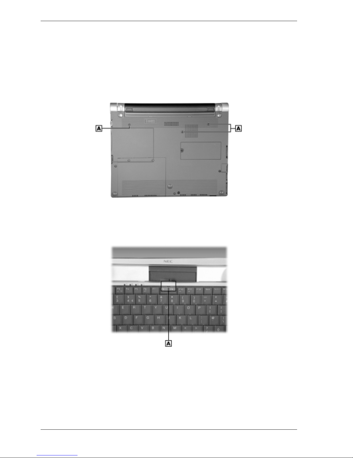
Keyboard
Remove the keyboard assembly as follows.
1.
Save any open files, exit Windows, turn off notebook power, unplug the power cable, and
disconnect any peripheral devices.
2.
Close the LCD panel, turn the notebook over, and remove the secondary battery.
3.
Remove the three screws holding the keyboard in place.
Removing the keyboard screws
A – Keyboard Screws (3)
4.
Turn the notebook over, open the LCD panel, and locate the slot on the keyboard above and
between the F8 and F9 keys.
Removing the keyboard
A – Keyboard Slot
5.
Insert the blade of a small flat-blade screwdriver into the slot and pull up on the keyboard
enough to gain access to the keyboard cable.
6.
Use care in this step to avoid damage to the keyboard cable clamp. Release the keyboard
cable from main board connector P8 by gently grasping the cable clamp at the left and right
corners (nearest the cable insertion point) and pulling up on the corners (the clamp pivots up
at an angle). Slide the cable out of the connector and set the keyboard aside. Press the clamp
down on the connector to avoid breaking the clamp while disassembling.
3-6 Disassembly and Reassembly
Page 48

Top Cover Assembly
Remove the top cover assembly as follows.
Note
The assembly is replaceable as a whole unit.
1.
The top cover assembly consists of the top cover, VersaGlide Touchpad, and speaker.
Save any open files, exit Windows, turn off notebook power, close the LCD panel, unplug
the power cable, and disconnect any peripheral devices.
2.
Remove the secondary battery, hard drive cover, and keyboard.
The two screws securing the hard drive cover and the three screws securing the keyboard
also partially secure the front cover assembly.
3.
On the bottom of the notebook, remove
! two adhesive-backed feet (
! two long screws (
! three short screws (
A
)
C
)
B
)
Removing the bottom screws
4.
Turn the system over and open the LCD panel.
A – Long Screws (2) C – Foot (2)
B – Short Screws (3)
Disassembly and Reassembly 3-7
Page 49

5.
Open the LCD panel approximately half way. Remove the left and right inside caps by
carefully pushing each cap towards the middle of the notebook until it pops off the top
cover assembly. The caps are held tightly in place by three internal tabs.
Removing the inside cap
A – Left Inside Cap (right side similar)
6.
Unplug the following top cover assembly cables from the main board.
! Unplug the speaker cable from connector P18 on the main board. (The speaker is
fastened to the underside of the top cover.)
! Release the cable locks on connectors P9 and P10 on the main board and unplug the
two VersaGlide Touchpad cables from the connectors. Remove and save the tape
holding the two cables.
7.
Remove the six screws securing the top cover assembly.
Removing the top cover assembly screws
A
– Round Head Screws (4)
B
– Flat Head Screws (2)
8.
Carefully lift a corner of the top cover assembly to unsnap it from the base. Slowly work
around the cover, carefully unsnapping a small portion of the cover at a time.
When reassembling, be careful to align the top cover assembly with the base so that the
power slide switch is positioned against the inside wall of the base.
3-8 Disassembly and Reassembly
Page 50

During reassembly and after the cover assembly is snapped in place, check that the switch
slides smoothly and returns to the off position when released. Slide the switch and release it
quickly so that power is not turned on.
9.
Lift the top cover assembly off the two LCD panel hinges and remove the from the base.
Speaker
Remove the speaker from the top cover assembly as follows.
1.
Save any open files, exit Windows, turn off notebook power, close the LCD panel, unplug
the power cable, and disconnect any peripheral devices.
2.
Remove the secondary battery, hard drive cover, keyboard, and top cover assembly.
3.
Turn the top cover assembly over, carefully lift the black insulator off the speaker, and
remove the two screws fastening the speaker to the top cover assembly.
4.
Remove the speaker from its mount.
CMOS Battery
Remove the CMOS battery as follows.
1.
Save any open files, exit Windows, turn off notebook power, close the LCD panel, unplug
the power cable, and disconnect any peripheral devices.
2.
Remove the secondary battery, hard drive cover, keyboard, and top cover assembly.
Note
customized BIOS settings are lost when the CMOS battery is disconnected.
3.
Be sure that the BIOS settings are recorded before removing the CMOS battery. Any
Unplug the CMOS battery from connector P36 on the communication board (see the
following figure “Removing the Mini PCI Board” for connector location).
4.
Remove the CMOS battery from the base.
USB Connector Board
Remove the USB connector board as follows.
1.
Save any open files, exit Windows, turn off notebook power, close the LCD panel, unplug
the power cable, and disconnect any peripheral devices.
2.
Remove the secondary battery, hard drive cover, keyboard, and top cover assembly.
3.
Unplug the following cables from the USB connector board (see the following figure
“Removing the Mini PCI board” for board and connector locations):
! Mini PCI board cable from connector P43 on the USB connector board
! main board cable from connector P41 on the USB connector board.
4.
Open the three access panels covering the USB connectors, and lift the USB connector
board off its guide pin on the base. Remove the USB connector board from the base.
5.
Remove the two screws fastening the board to its frame. Save the frame and screws.
Disassembly and Reassembly 3-9
Page 51

Mini PCI Board
Remove the Mini PCI LAN/modem board as follows.
1.
Save any open files, exit Windows, turn off notebook power, close the LCD panel, unplug
the power cable, and disconnect any peripheral devices.
2.
Remove the secondary battery, hard drive cover, keyboard, and top cover assembly.
3.
Unplug the Mini PCI board cable from connector P34 on the communication board and the
Mini PCI board cable from connector P43 on the USB connector board (see the following
figure).
4.
Remove the two screws securing the Mini PCI board to the communication board.
5.
Unplug the PCI board from connector P32 on the communication board.
6.
Remove the Mini PCI board from the base.
Removing the Mini PCI board
A – Mini PCI Board Cable Connector P34 G – Mini PCI Board
B – CMOS Battery H – CMOS Battery Connector P36
C
– Main Board Cable Connector P41 I – PCI Board Connector P32 (under board)
D
– USB Connector Board
E
– Mini PCI Board Cable Connector P43
F
– Communication Board
Power Switch Board
Remove the power switch board as follows.
1.
Save any open files, exit Windows, turn off notebook power, close the LCD panel, unplug
the power cable, and disconnect any peripheral devices.
2.
Remove the secondary battery, hard drive cover, keyboard, and top cover assembly.
3.
Unplug the signal cable from connector P5 on the power switch board (see the previous
figure “Removing the Mini PCI board” for board and connector locations).
4.
Carefully lift the power switch board out of the base.
You might need to flex the side of the base to release the board.
Use care to prevent loss of the plastic power slide switch between the hard drive bay and the
side of the base.
3-10 Disassembly and Reassembly
J
– Power Switch Board
K
– Main Board Cable Connector P51
Page 52
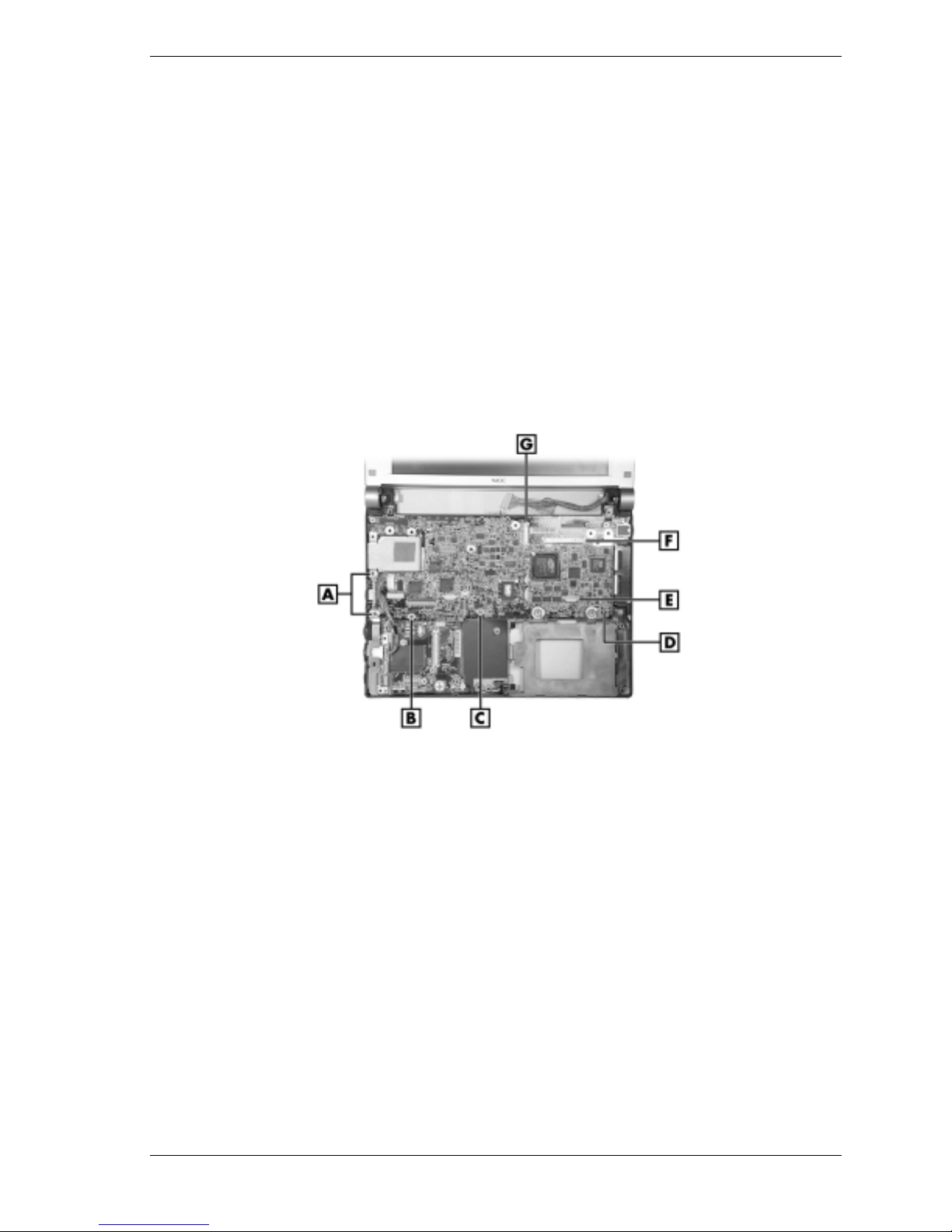
Main Board
Remove the main board as follows.
1.
2.
3.
4.
5.
6.
Save any open files, exit Windows, turn off notebook power, close the LCD panel, unplug
the power cable, and disconnect any peripheral devices.
Remove the secondary battery, hard drive, keyboard, top cover assembly, and USB
connector board.
If installed, remove the PC Card or dummy card from the PC Card bay.
Unplug the LCD panel cables from connectors P20 and P2 on the main board (see the
following figure for connector locations).
Unplug the switch board cable from connector P16 on the main board.
Remove the screws (A, B, C on the figure) fastening the main board to the base.
Removing the main board
A – Long Screws (2) E – Switch Board Connector P16
B – Short Black Screw (1) F – LCD Panel Connector P2
C – Short Silver Screw (1) G – LCD Panel Connector P20
D – Main Board
Carefully lift the main board off the base.
7.
You might need to flex the sides of the base to allow clearance for board removal.
When reinstalling the main board, use care to prevent damage to the PC Card ejection lever.
8.
Set the main board on a static-free surface.
If replacing the board, remove and save the processor assembly, memory module, and Mini
PCI board for installation on the new board.
Disassembly and Reassembly 3-11
Page 53

Processor Assembly
Remove the processor assembly as follows.
1.
Save any open files, exit Windows, turn off notebook power, close the LCD panel, unplug
the power cable, and disconnect any peripheral devices.
2.
Remove the secondary battery, hard drive cover, keyboard, top cover assembly, USB
connector board, and main board.
3.
Lift the processor assembly off its four standoffs on the base. Store the assembly in a staticfree bag.
Removing the processor assembly and communication board
A – Processor Assembly D – LAN Connector
B – Processor Standoff (1 of 4) E – Micro Switch Connector P37
C – Communication Board F – Mini PCI Board Connector P32
Communication Board
Remove the communication board as follows.
1.
Save any open files, exit Windows, turn off notebook power, close the LCD panel, unplug
the power cable, and disconnect any peripheral devices.
2.
Remove the secondary battery, hard drive, keyboard, top cover assembly, Mini PCI board,
USB connector board, and main board.
3.
Unplug the following cables from the communication board (see the preceding figure
“Removing the processor assembly and communication board” for cable connector and
component locations):
! LAN connector cable from connector P35
! CMOS battery cable from P36 or, to avoid losing BIOS customized settings, move the
battery off the base, out of the way, without unplugging the cable
! microswitch cable from connector P37.
4.
Remove the screw and standoff fastening the communication board to the base.
5.
Remove the board from the base.
3-12 Disassembly and Reassembly
Page 54

LCD Panel
Remove the LCD panel as follows.
1.
Save any open files, exit Windows, turn off notebook power, close the LCD panel, unplug
the power cable, and disconnect any peripheral devices.
2.
On the back of the notebook, remove the adhesive backed foot and screw from each side of
the battery bay. The two screws partially secure the LCD panel to the base.
3.
Remove the secondary battery, hard drive, keyboard, top cover assembly, and main board.
4.
Remove the screw and cable clamp securing the LCD panel cable in place on the base (see
the preceding figure “Removing the processor assembly and communication board” for
clamp and cable locations).
5.
On each side, remove the screw securing the LCD panel hinge bracket to the base (the
following figure shows the left side hinge bracket and screw, the right side is similar).
6.
Remove the LCD panel and place in a safe place.
Removing the LCD panel screw
A – Bracket Screw (left side) B – LCD Panel Hinge Bracket (left side)
Reassembly
Reassembly is the reverse of the disassembly process. Use care to ensure that all cables and
screws are returned to their correct positions.
Check that the power switch on the side of the notebook slides smoothly and does not bind. If it
does not slide smoothly, remove the top cover assembly (see “Top Cover Assembly” earlier in
this section for removal procedures). Reseat the top cover assembly, ensuring that the power
switch is against the side of the base while snapping the top cover assembly in place.
Disassembly and Reassembly 3-13
Page 55

System Boards
!
Mini-PCI Board
!
Power Switch Board
!
USB Connector Board
!
Main Board
!
Communications Board
4
Page 56
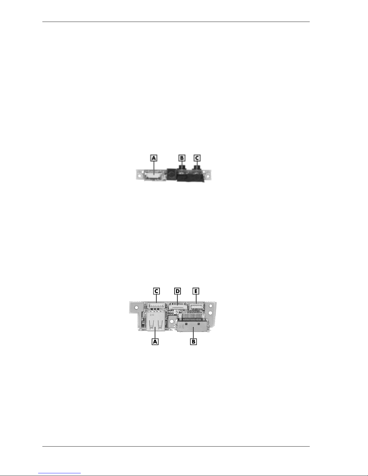
This chapter includes information on the five circuit boards used in the notebook.
Mini PCI Board
The Mini PCI LAN/modem board is located under the top cover assembly. The board is
mounted on the communications board. The Mini PCI board connectors include
communications board cable connector J1, a modem cable connector, and a LAN cable
connector.
Power Switch Board
The power switch board (G7EZAB) is located under the top cover assembly. The board is
mounted on the right side of the notebook, between the hard drive bay and the side of the base.
The following figure shows the board and its connectors and ports.
A – Main Board Cable Connector P51 C – Headphone Jack P53
B – Microphone Jack P52
Power switch board
USB Connector Board
The USB connector board (G7EWK A 2/3) is located under the top cover assembly. The board
is mounted on the left side of the notebook. The following figure shows the board and its
connectors and ports.
A – USB Port D – Cable Connector P42
B – Parallel Port E – Mini PCI Board Cable Connector P43
C – Main Board Cable Connector P41
USB connector board
4-2 System Boards
Page 57

Main Board
The main board (G7EZA B A2) is located under the keyboard and the top cover assembly . The
following figure shows the board and its connectors and ports. The back of the main board
contains the processor (non-removable), communications board connector P12, memory module
connector P1, hard drive connector P6, and a DIP switch.
Main board connectors
A – Secondary Battery Connector P11 H – VersaGlide Touchpad Cable Connector P10
B – LCD Panel Cable Connector P20 I – Speaker Cable Connector P18
C – LCD Panel Cable Connector P2 J – Cable Connector P14 (not used)
D – USB Port P4 K – Keyboard Cable Connector P8
E – PC Card Bay L – Cable Connector P19 (not used)
F – Power Switch Board Cable Connector P16 M – Monitor Connector Port P15
G – VersaGlide Touchpad Cable Connector P9 N – USB Board Cable Connector P5
Communications Board
The communications board (G7EWK B A 1/3) is located under the top cover assembly. The
board is connected to the main board. The following figure shows the board and its connectors.
Communications board connectors
A – Main Board Connector P31 E – Cable Connector P35 (not used)
B – Mini PCI Board Connector P32 F – CMOS Battery Cable Connector P36
C – Cable Connector P33 (not used) G – Microswitch Cable Connector P37
D – Mini PCI Board Cable Connector P34
System Boards 4-3
Page 58

Illustrated Parts Breakdown
!
Illustrated Parts Breakdown
!
Parts List
5
Page 59

Illustrated Parts Breakdown
The NEC Versa UltraLite/DayLite notebook computers illustrated parts breakdown (IPB) is
shown in the following figure. See the table, “Field-Replaceable Parts List,” later in this chapter
for a list of field-replaceable unit (FRU) parts.
NEC Versa UltraLite/DayLite Notebook illustrated Parts Breakdown
5-2
Illustrated Parts Breakdown
Page 60

Parts List
The following table contains a listing of the NEC Versa UltraLite/DayLite notebook computers
field-replaceable unit (FRU) parts.
Field-Replaceable Parts List
Item Description
1 USB Connector Board Cable
2 USB Connector Board
3 USB Connector Board Bracket
4 RJ-11 Connector Assembly
5 CMOS Battery
6 Base, Bottom
7 Main Board (G7EZAD)
8 Heatsink Assembly
9 Speaker Assembly
10 128-MB Memory Module
11 Communications Board (G7EWKBA, 1/3)
12a
12b
13 Keyboard
14 LCD Panel (shown for reference purposes only)
15 Secondary Battery, 3-Cell
16 Outer and Inner LCD Hinge Caps (left and right)
17 Mini PCI LAN/Modem Board Modem Cable
18 Mini PCI LAN/Modem Board LAN Cable
19 Mini PCI LAN/Modem Board
20 Dummy PC Card
21 Power Switch Board Cable
22 Power Switch
23 Power Switch Board
24 Power Switch Board Bracket
25 Hard Drive, 10 MB or 20 MB
26 Hard Drive Access Panel
27 Hard Drive Cable
Top Cover
VersaGlide Touchpad
28a
28b
Foot, Rear
Foot, Front
Illustrated Parts Breakdown 5-3
Page 61

Field-Replaceable Parts List
Item Description
* External USB CD-ROM Drive
* External USB Diskette Drive
* UltraLite Backlight LCD Panel
* DayLite Reflective LCD Panel
* DayLite Transflective LCD Panel
*
*
*
*
*
*
*
*
*
*
UltraLite Backlight LCD Cable
DayLite Reflective LCD Cable
DayLite Transflective LCD Cable
UltraLite Backlight Inverter
DayLite Transflective Inverter
Speaker Bracket
Speaker Cable
Auto Adapter
Auto Adapter DC Cable
Microphone and Cable Assembly
* Item not shown on IPB.
5-4
Illustrated Parts Breakdown
Page 62

Preventive Maintenance
!
Cleaning the Exterior
!
Cleaning the Interior
!
Protecting the Hard Disk Drive
!
Maintaining the Secondary Battery
6
Page 63

This section contains general preventive maintenance information for cleaning the notebook
case, LCD, and keyboard.
battery, if installed) before performing maintenance. Voltage is present inside the notebook and
LCD even after it is turned off.
Cleaning the Exterior
Clean the exterior of the notebook as follows.
1.
Power off the notebook, unplug all cables and peripherals connected to the notebook, and
remove the secondary battery (or optional battery, if installed).
contain caustic materials. These cleaners are usually high in alkalinity which can cause the
notebook case to crack or discolor.
2.
Wipe the outside of the notebook with a slightly damp, almost dry soft, clean cloth. Never
use solvents or strong, abrasive cleaners on any part of the notebook.
3.
Clean the LCD screen with a soft lint-free cloth or a screen wipe designed for that purpose.
Unplug the AC adapter and remove the secondary battery (or optional
Never use harsh solutions, household cleaners, or spray cleaners that
4.
Clean the keyboard with a slightly damp, almost dry soft, clean cloth. If necessary, use a
small, soft-bristle brush to clean between the keys.
5.
Periodically use a head-cleaning diskette in the USB diskette drive to prolong the life of the
drive and to help maintain data integrity. Do not use abrasive head cleaning kits (kits
without cleaning solution).
Cleaning the Interior
Clean the interior of the notebook as follows.
1.
Remove the front cover and VersaGlide™ assembly, keyboard, and top cover to access the
interior of the notebook (see Chapter 3, “Disassembly and Reassembly” for procedures).
2.
Dust or use a vacuum specifically designed for computer use (with a rubber-tipped nozzle)
to clean inside the notebook, particularly the main board surface. Use care to avoid
damaging or dislodging any components or cables.
3.
Inspect all cables connectors for damage. Ensure that connectors are seated properly before
replacing the removed assemblies.
Protecting the Hard Drive
To protect the hard drive and data, back up the drive periodically on diskettes, CD-RW discs, or
a network drive.
Here are some tips to use when servicing a hard drive:
!
Do not squeeze the top and bottom of the hard drive or the drive might be damaged.
!
Always back up the data files on the hard drive.
!
Run a virus detecting program to check for possible virus infected areas on the hard drive.
6-2 Preventive Maintenance
Page 64

!
Use the Microsoft® Windows® operating system ScanDisk program to correct any errors
found in the directory and File Allocation Table (FAT). This also frees up space from any
unused sectors.
!
Never turn the notebook off when the hard drive is being accessed.
!
Use a hard drive maintenance program like the Microsoft Windows operating system
DEFRAG program to eliminate fragmentation and improve the hard drive access time.
Maintaining the Secondary Battery
Periodically inspect the secondary battery (or optional battery) terminals and the battery for
evidence of corrosion and oxide build-up.
Observe the following precautions when handling the secondary battery.
!
Observe the safety precautions outlined under “Secondary Battery Handling” in Section 2,
“System Configuration and Setup.”
!
Do not drop the secondary battery or subject it to excessive shock and vibration.
!
Do not expose the secondary battery to direct sunlight, moisture, chemical compounds, or
extreme heat.
!
Do not disassemble the secondary battery.
!
Do not use the secondary battery to power other devices.
!
Never attempt to charge the secondary battery in any way other than as described in this
manual (see Section 2, “Batteries”) and the user’s guide.
!
Always charge the secondary battery as soon as possible after a low battery indication.
Preventive Maintenance 6-3
Page 65

Troubleshooting
!
Problem Checklist
!
Startup Problems
!
Diagnostics
7
Page 66

This chapter provides information to help isolate and repair notebook malfunctions at the field
level. The notebook has a built-in program that automatically checks its components when the
notebook is powered on. If there is a problem, the notebook displays an error message. If this
happens, follow any instructions on the screen.
If screen messages do not help or an error message does not appear, refer to the information in
this chapter to help determine and correct the problem. For the more common problems, refer to
“Problem Checklist” for assistance. If the information in the checklist does not help, refer to
“Startup Problems” for additional help. See “Diagnostics” for more detailed problem solving.
If disassembly is required, see Section 3, “Disassembly and Reassembly.” Jumper setting
information is given in Section 2, “System Configuration.”
Problem Checklist
Check the items in the following list. If these items don't help, see the “Troubleshooting” table
that follows the list.
!
Check that power is on to the notebook.
!
Check that the AC adapter is plugged into a working electrical outlet. Test the outlet by
plugging in a lamp or other electrical device.
!
Check that all cables are securely plugged in.
!
Check that the display setting is configured correctly.
!
Check that the display’s brightness control is adjusted properly.
!
If using battery power, check that the secondary battery is properly inserted and fully
charged.
Troubleshooting
Problem What to Do
The notebook does not power
on.
LCD screen is dark and blank. Power-saving mode has shut off the backlight. Recover by
Battery power does not last
long.
If you are operating the notebook with battery power, check that
the secondary battery is correctly inserted. Attach the AC adapter
to recharge the battery.
If you have the AC adapter attached, check that the electrical
outlet you are using works.
pressing any keyboard key.
Fn-F3
The built-in LCD may not be selected. Press
Screen brightness needs adjustment. Use the Fn-F8 and Fn-F9
keys.
The notebook entered Standby mode due to low battery power.
Use the power meter to check battery status. Plug in the AC
adapter or replace the battery, and then press the power button
to resume operation.
Use power-saving modes.
Fully charge and fully discharge the battery several times to
recondition it.
once or twice.
7-2 Troubleshooting
Replace the battery.
Page 67

Troubleshooting
Problem What to Do
Information on the LCD screen
is difficult to see.
An optional component does
not work.
The power button does not
resume the notebook from
Standby mode.
The notebook does not autosuspend (Standby).
Upon resuming from a manual
STF, the notebook displays the
message “Following system
component(s) changed since
last suspend – Do you want to
(B)oot or (P)ower down?
Startup Problems
The notebook displays an invalid configuration error message at power on and when there are
the following conditions:
Use the Fn-F8 and Fn-F9 function keys to adjust the brightness
control.
Make sure the component is securely installed or connected.
Verify that the parameter for the I/O port configuration is set
correctly in Setup.
If the notebook does not resume, it may have auto suspend
suspended (Standby) or a low battery. Attach the AC adapter and
try again.
Check that the “System Switch” BIOS parameter is set to “Sleep.”
A disk drive might be busy. Wait until the disk drive stops and try
again.
Check that Auto Play is disabled.
Power down the notebook and reseat the memory.
If new memory was installed prior to manual STF, remove the
new memory before resuming.
!
current configuration information doesn't match configuration information stored in Setup,
such as when an internal option is added.
!
notebook loses configuration information.
If either condition is true, the notebook displays an invalid configuration information message.
To continue start-up procedures, press
current notebook parameters.
Note
either the LCD or a CRT. The notebook warns you by beeping.
When the notebook detects an error related to display devices, it cannot display on
POST Error Messages
The notebook computer has a built-in Power-On Self-Test (POST) checking program that
automatically tests its components when you turn power on. If the notebook finds a problem
during POST, it displays an error message or emits a series of beep signals. If this happens,
follow the instructions in the “POST Error Messages” table or the “Beep Code” table, as
appropriate.
If an error message appears before the operating system starts, look up the error message in the
following table and follow the instructions. If you see other error messages, the hardware might
need repair.
F2
(or
F1
when prompted) and run the Setup utility to set
Troubleshooting 7-3
Page 68

Post Error Messages
Message Resolution
Address line is short Error in the address decoding circuit on the main board.
C: Drive Error Hard disk drive C: does not respond. Confirm that C: hard disk
type in Setup is correct.
C: Drive Failure Hard disk drive C: does not respond. Replace the hard disk drive.
Cache Memory Bad, Do
Not Enable Cache
CH-2 Timer Error Most ISA computers include two timers. There is an error in timer
CMOS Battery State Low CMOS RAM is powered by a battery. The battery power is low.
CMOS Checksum Failure After CMOS RAM values are saved, a checksum value is
CMOS System Options
Not Set
CMOS Display Type
Mismatch
CMOS Time and Date Not
Set
Diskette Boot Failure The boot diskette is corrupt. It cannot be used to boot the
DMA Error Error in the DMA controller. Replace the CMOS battery.
DMA#1 Error Error in the first DMA channel.
Cache memory is defective. It must be replaced.
2.
Connect the system to AC power to charge the CMOS battery. If
the battery does not charge, replace the CMOS battery.
generated for error checking. The previous value is different from
the current value. Run Setup to reset the value.
The values stored in CMOS RAM are either corrupt or
nonexistent. Run Setup to reset the value.
The amount of memory on the main board is different than the
amount in CMOS RAM. Run Setup to reset the value.
Run Setup to set the time and date.
notebook. Use another boot disk and follow the on-screen
instructions.
DMA#2 Error Error in the second DMA channel.
FDD Controller Failure The BIOS cannot communicate with the floppy disk controller.
HDD Controller Failure The BIOS cannot communicate with the hard disk drive
INTR #1 Error Interrupt channel 1 failed POST.
INTR #2 Error Interrupt channel 2 failed POST.
Invalid Boot Diskette The BIOS can read the diskette in the disk drive, but cannot boot
Keyboard is Locked
Unlock It
Keyboard Error There is a timing problem with the keyboard. Set the keyboard
KB/interface Error There is an error in the keyboard connector.
7-4 Troubleshooting
Check all appropriate connections.
controller. Check all appropriate connections.
the notebook. Use another boot diskette.
The keyboard lock on the notebook is engaged. The notebook
must be unlocked to continue.
option in Setup to “Not Installed” to skip the keyboard POST
routines.
Page 69

Message Resolution
Off Board Parity Error Parity error in an expansion slot. Check that the memory module
On Board Parity Error Parity error in main board memory.
Parity Error Parity error in system memory at an unknown address.
Beep Codes
Fatal errors that occur during POST are communicated through a series of beeps. All beep code
errors, except beep code 8, are fatal errors and do not allow the notebook to continue to boot.
If beep codes occur during POST, check the items in the Problem Checklist (at the start of this
chapter), verify that all the hardware is set up properly and securely connected, and try
rebooting. If you still get a beep code, go to the section “If You Need Assistance” at the end of
this chapter.
Beep Codes are listed in the following table.
Post Error Messages
is installed correctly.
The error format is:
OFF BOARD PARITY ERROR
ADDR(HEX) = (XXXX)
XXXX is the hex address where the error occurred.
Beep Codes
Number of
Beeps Error Description
1 Refresh Failure The memory refresh circuit on the
main board is faulty.
2 Parity Error Parity error in the first 64 KB of
memory.
3 Base 64 KB Memory
Failure
4 Timer Not Operational Memory failure in the first 64 KB of
5 Processor Failure The CPU on the main board
6 Gate A20 Failure The keyboard controller may be bad.
7 Processor Exception
Interrupt Error
8 Display Memory
Read/Write Error
Memory failure in the first 64 KB.
memory or Timer 1 on the main board
is not functioning.
generated an error.
The BIOS cannot switch to protected
mode.
The CPU generated an exception
interrupt.
The system video adapter is either
missing or its memory is faulty. (This
is not a fatal error.)
9 ROM Checksum Error The ROM checksum value does not
match the value encoded in the BIOS.
Troubleshooting 7-5
Page 70

Beep Codes
Number of
Beeps Error Description
10 CMOS Shutdown
Register Read/Write
Error
11 Cache Error/External
Cache Bad
The shutdown register for CMOS
RAM failed.
The external cache is faulty.
Diagnostics
This section summarizes problems that might develop during notebook operation and lists
suggested corrective actions.
Diagnostics
Problem or Symptoms Corrective Actions
No power Check that the AC adapter is plugged into the power port of the
notebook. Also, check that the AC adapter is plugged into a properly
grounded and working AC power outlet.
Check that the secondary battery is the correct type, charged properly,
and is inserted correctly.
Power LED is on but no
display and notebook does
not turn on
Check if the memory module is inserted properly.
Check that the CPU is inserted properly.
Display on the LCD can not
be read
LCD screen does not show
display
Replace the memory module, CPU, or main board.
Adjust the brightness.
Check if the installed driver is correct and resolution is set according to
the LCD size and type.
Check if the LCD panel is connected properly.
Replace the main board.
Check if the power saving mode is activated. Press any key or press
the power button to resume operation and display.
Check if the display output is switched to the external monitor.
Check if there is power.
Check if the LCD panel is disconnected or loose.
Replace the LCD panel.
7-6 Troubleshooting
Page 71

Diagnostics
Problem or Symptoms Corrective Actions
Battery power does not last
long
Notebook halts during boot
sequence
I/O processing malfunctions Check the connections of all internal devices.
USB diskette drive does not
work
Make sure that the power management options under BIOS Setup are
enabled and set properly.
Recharge the secondary battery for at least 4.5 hours before using.
Discharge and recharge the secondary battery twice.
Replace the secondary battery.
Check condition of the selected bootload device (diskette or hard drive)
for bad boot track or incorrect O/S files.
Try booting from a new boot diskette and recopy or repartition the hard
drive.
Check for any BIOS error messages on the display.
Replace the main board.
Replace the main board.
Check if the diskette drive option is set properly in BIOS Setup.
Check if the diskette USB cable is connected properly.
Check that the diskette is not faulty.
Replace the USB diskette drive.
Replace the main board.
Hard drive malfunction Check if the hard drive is set properly in BIOS Setup.
Check that the hard drive interface cable is firmly connected to P9 on
the main board and that the cable is firmly connected to the hard drive.
Try reseating the interface cable to the main board and to the hard disk
drive.
Replace the hard drive.
Replace the main board.
USB CD-ROM drive
malfunction
Check if the drive is set properly in BIOS Setup.
Check if the drive has the latest software driver (check the internet for
the vendor’s latest driver).
Check that the USB cable is connected properly.
Check the drive with a different CD.
Troubleshooting 7-7
Page 72

Diagnostics
Problem or Symptoms Corrective Actions
Memory malfunction Check if the memory module is seated properly.
Reseat the module.
Replace the memory module.
Replace the main board.
PC Card does not work Check if the PC Card is correctly inserted.
Check that the PC Card is the correct type.
Replace the PC Card.
Check the PC Card software for malfunctions.
Check if the PC Card assembly is firmly plugged into its connector on
the main board. Otherwise, replace the PC Card assembly.
Replace the main board.
NEC VersaGlide™ Touchpad
does not work
USB port does not work Check if the USB controller in BIOS Setup is enabled.
Audio components do not
work
Check if the PS/2 or Alps mouse driver is properly installed.
Check if the VersaGlide Touchpad cable is firmly connected to P18 on
the main board.
Replace the front panel and VersaGlide Touchpad assembly.
Replace the main board.
Check the USB device connection. Unplug and reseat the device.
Check if the USB port driver and the USB device driver are installed.
Replace the USB device or contact the USB device manufacturer for
support.
Replace the main board.
Check that the external connections are set properly.
Check if the audio source (CD, tape) is faulty.
Check if the audio driver is installed.
Check if the internal connections for speaker and microphone are
working.
7-8 Troubleshooting
Check the sound board, cables, and connections.
Replace the main board.
Page 73

8
NEC Computers Information Services
!
Service and Support Functions
!
Technical Support
Page 74

This chapter contains the following NEC Computers service and support information:
!
service and support telephone numbers and web addresses
!
technical support.
Service and Support Functions
The following table lists the telephone numbers and web addresses for the NEC Computers
service and support functions.
NEC Computers Service and Support Telephone and Web Addresses
Service Telephone Numbers and Web Addresses
To contact NEC Computers Technical
Support Center:
To order spare parts: Call 800-632-4525
To send technical questions by email: tech-support@nec-computers.com
To access the NEC Computers web site: www.neccomp.com
Technical Support
The following sections provide information for obtaining technical support from NEC
Computers. With access to a telephone and/or modem, you can use these services to obtain
information about the system at any time, day or night, seven days a week.
NEC Computers Web Site
If you have access to the Internet (via a network or a modem connection), you can access the
NEC Computers web site. You can do this through a commercial online service or through your
Internet account. The NEC Computers web site contains general information about NEC
Computers and its products. The web site also contains press releases, reviews, and service and
support information.
Look in the Service and Support area for the following:
!
technical documentation, including Frequently Asked Questions, user’s guides, reference
manuals, and warranty information
In the U.S., call 800-632-4525
!
BIOS updates and drivers to download
!
contact information, including telephone numbers for Technical Support and links to vendor
web sites
!
automated email form for your technical support questions
!
a password-accessible area for Resellers.
To access the NEC Computers web site, enter the following Internet Uniform Resource Locator
(URL) in your browser:
http://www.neccomp.com
8-2 NEC Computers Information Services
Page 75

Email to Technical Support Services
The NEC Computers Technical Support Center offers technical support by email over the
Internet network if you have access. The Internet email address is:
tech-support@nec-computers.com/
When using the email support service, please include the word
prompt response from the appropriate technical person.
Provide as much specific information in your questions as possible. You should receive a
response to your questions within one business day.
NEC Computers Technical Support Services
NEC Computers also offers direct technical support through its Technical Support Center. (NEC
Computers technical support is for U.S. and Canadian customers only; international customers
should check with their sales provider.)
Direct assistance is available 24 hours a day, 7 days a week. Call the NEC Computers Technical
Support Center, toll free, at
1-800-632-4525
Please have the system accessible when you call the Technical Support Center so that a
technician can troubleshoot the system.
For callers outside the U.S. or Canada, please contact your local NEC Computers sales provider.
(U.S. and Canada only).
Notebook
in the subject field for
NEC Computers Information Services 8-3
Page 76

Specifications
!
System Components
!
Memory Map
!
Interrupt Controllers
9
Page 77

System Components
The following system component specifications are standard except where noted.
Note
The components that ship with the system are subject to change without notice.
System Processor
600-MHz Transmeta Crusoe TM5600 microprocessor
Architecture
64-bit Peripheral Component Interconnect (PCI)
Random Access Memory
!
System Memory
— 64-MB SDRAM on main board, 125-MHz SDRAM
— 128-MB SDRAM SO-DIMM module in single DIMM slot, 125-MHz SDRAM
— 192 MB total system memory (approximately 16 MB of total system memory shared
with video)
!
Cache Memory
— L1: 64-KB code and 64-KB data 8/16 way set associate, write back (data)
— L2: 512-KB built-in (4-way)
— operates at full core speed
— 4-GB cacheable range
Read-Only Memory
2-MB x 8-bit, Flash ROM
Calendar Clock
Year/month/day/hour/minute/second maintained by internal back-up battery
Input/Output (I/O) Facilities
Integrated industry-standard interfaces
!
Infrared — 1 FIR
!
VGA — 1 port, 20-pin (via CRT cable)
!
Mono microphone — 1 port, 3-pin, Mini Pin Jack
!
Stereo Headphones — 1 port, stereo 3-pin, Mini Pin Jack
!
DC In — 1 port, for AC adapter cable
!
USB ports — 2 ports, 4-pin
!
Modem — 1 port, RJ-11 modular jack
!
LAN I/F — 1 port, 26-pin
9-2 Specifications
Page 78

Speaker
LCD Panel
One built-in speaker, 1 watt
!
Mono speaker
!
Sound Blaster PRO compatible
!
ESS® Solo-1 PCI AudioDrive + ESS 1946S
!
Software-controlled sound and beep volume
!
UltraLite (Reflective)
— 10.4-inch high-resolution active-matrix illuminated reflective XGA
— 1024 x 768 resolution TFT display
!
DayLite (Reflective)
— 10.4-inch high-resolution active-matrix illuminated reflective SVGA
— 1024 x 768 resolution TFT display
!
DayLite (Transflective)
— 10.4-inch high-resolution active-matrix transmissive/reflective XGA
— 1024 x 768 resolution TFT display
!
Colors — 32 bit
Graphics
!
ATI® RAGE™ MOBILITY™-M graphics accelerator with 4-MB VRAM and 2X AGP
graphics capability
Keyboard
Membrane 86 keys with country-specific QWERTY-key layout
!
Function keys — 12 keys
!
Cursor Control keys — 8 functions on 5 keys; arrow keys arranged in inverted T layout
!
Numeric keypad — embedded
!
Fn key — function key for ROM-based key functions
!
Stroke — 2.5 mm
!
Height — 6 mm
!
Pitch — 17.5 mm
External USB Floppy Diskette Drive
!
Size — 3.5-inch
!
Capacity — 1.44 MB1 (formatted), 2 MB1 (unformatted)
!
Transfer Rate — 250 to 500 K/bps
!
Number of tracks — 160
Specifications 9-3
Page 79

Hard Drive
Specifications vary depending upon model:
!
!
!
!
!
!
!
1
When referring to storage capacity, GB stands for one billion bytes and MB stands for one million bytes.
Some utilities may indicate varying storage capabilities. Total user-accessible capacity may vary depending
on operating environments.
PC Card Slots
!
!
Busmaster IDE, Ultra DMA/33 support
Capacity — Internal 10- or 20-GB
Drive height — 9.75 mm
1
Read/write track-to-track seek rate — 3 ms
Average seek time — 12 ms – 14 ms
Revolutions per minute — 4200
Data transfer rate
— 16.6 MB/sec (PIO mode4/DMA mode2)
— 66.6 MB/sec (ultra DMA mode 4)
One 32-bit card slot for a Type II card, 5 V or 3.3 V interface
32-bit CardBus support
External 24X-Maximum/10X-Minimum Variable Speed USB CD-ROM Drive
!
Type — 5-inch CD-ROM Pack
!
Average Data Transfer Rates — 1545 KB/second to 3600 KB/second
!
Burst Transfer Rate — 16.7 MB/second, PIO mode4/DMA mode
!
Average Access Time
— 190 ms (Random)
— 350 ms (Fullstroke)
!
Photo CD Compatibility — Single Session/Multisession Photo CD,
Video CD (CD-1, CD-I Ready, CD-G, CD-Plus, CD-DA,
CD-EXTRN, and CD-ROM XA mode 2)
Internal Xircom
®
Mini PCI LAN/Modem Combo
!
10BASE-T and 100BASE-TX compatible
!
IEEE 802.3 and IEEE 802.3u compliant
!
10/100 Mbps transmission rate
!
10/100M, LINK, and ACT diagnostic LEDs
!
V.90 data/V.17 fax soft, MMX optimized
!
K56flex™ compatible
!
SmartDAA™ technology
!
V.80 synchronous access mode
9-4 Specifications
Page 80

Power
AC Adapter
Batteries
Dimensions
!
Input Voltage — 100 to 240 volts (V) AC, 50 or 60 Hz, maximum 2.8A
!
Output Voltage — 16.0 V DC, 45 watt
!
Australia, Europe, and Asia use an AC power cable specific to each country's standards.
!
Primary Battery
— DayLite Transflective, 9-cell Lithium Polymer
— DayLite Reflective, 9-cell Lithium Polymer
— UltraLite Reflective, 12-cell Lithium Polymer
!
Secondary Battery — 3-cell Lithium Ion; 10.9 volts, 2000 mAh
!
Recharging Time — Approximately 8 hours when the system is on, 4.5 hours when off.
!
Width — 10.4 in. (264 mm)
!
Depth — 8.3 in. (211 mm)
!
Height — 1.06 in. (27 mm)
Weight
3.3 lb. (1.39 kg) — without external drives
Recommended Environment
Operation
!
Temperature — 41°F to 95°F (5°C to 35°C)
!
Relative Humidity — 20% to 80% (Noncondensing)
Storage
!
Temperature — -4°F to 104°F (-20°C to 40°C)
!
Relative Humidity — 20% to 80% (Noncondensing)
Specifications 9-5
Page 81

Memory Map
The system supports system and video shadowing, both controlled through complementary
metal oxide semiconductor (CMOS). The system supports BIOS as a cacheable area with write
protection. The following table shows the system's memory map.
Memory Space Size Function
FFFE 0000H-FFFF FFFFH 128K Upper ROM, System and Video
FFFC 0000H-FFFD FFFFH 128K Lower ROM, Power Management
System Memory Map
BIOS
BIOS
FFFA 0000H-FFFB FFFFH
FFF8 0000H-FFF9 FFFFH
FFF0 0000H-FFF7 FFFFH 512K 1MB Extended, BIOS 512KB
0A00 0000H-0BFF FFFFH Up to 176MB Extended Memory
000F 0000H-000F FFFFH
000E 0000H-000E FFFFH
000A 0000H-000B FFFFH 128K Video Buffer Ram
000C 0000H-000D FFFFH 128K Available for Applications
0000 0000H-0009 FFFFH 640K System/Application Memory
128K
128K
64K
64K
New Extended Area
System BIOS, 128K
9-6 Specifications
Page 82

Interrupt Controllers
Using interrupts, hardware can request software services. If non-Plug and Play software is being
used, the interrupt may need to be moved for software application or driver compatibility. Some
interrupts cannot be moved. Fifteen interrupts can be used with a cascade connection of
8259INTC x 2. The table shows default interrupt level assignments 0 through 15, in order of
decreasing priority.
Priority Name Device
0 IRQ00 Internal Timer 1
1 IRQ01 Keyboard
2IRQ02 PIC
3 IRQ08 Real-time Clock
4 IRQ09 SCI, CardBus, Modem, LAN
5 IRQ10 Video
6 IRQ11 Sound
7 IRQ12 Mouse
8 IRQ13 Coprocessor
9 IRQ14 IDE Controller
10 IRQ15 (Free)
11 IRQ03 or IRQ04 (Free) Infrared Port
12 IRQ04 or IRQ03 (Free)
13 IRQ05 or IRQ09 USB
14 IRQ06 (Free)
15 IRQ07 (Free)
1
When enabled.
1
Specifications 9-7
Page 83

Glossary
A
applications programs
Software designed to perform specific functions, like solving business or mathematical
problems.
AC Adapter
A device that connects an NEC Versa portable computer and an AC wall outlet to provide
AC power for running the system or recharging the battery.
AGP
Advanced Graphics Port is an interface specification designed for the throughput demands
of 3D graphics. AGP introduces a point-to-point channel allowing the graphics controller
direct access to main memory, increases bandwidth to 266-MBps, and supports throughputs
of 533-MBps and 1.07-GBps.
B
base RAM
Area of system memory between 0 and 640 kilobytes available to the user for operating
system and application programs.
BIOS
Basic Input Output System. A collection of primitive computer routines, usually burnt into
ROM, that controls the real-time clock, keyboard, disk drives, video display, and other
peripheral devices.
bit
Binary digit. The smallest unit of computer data.
bits per second
(bps) A unit of transmission. Also called baud rate.
board
Printed circuit board. Board onto which computer components are soldered and thin wires
are printed to connect the components.
boot
To start up a computer. See cold boot and warm boot.
bus
An electronic circuit within a computer used for transmitting data or electrical power from
one device to another.
byte
Group of eight contiguous bits.
Glossary 1
Page 84

C
clock
Electronic timer used to synchronize computer operations.
CMOS
Complementary Metal Oxide Semiconductor. A chip that contains nonvolatile memory in
the NEC Versa. CMOS is backed up by an internal lithium battery that preserves
clock/calendar data and system configuration parameters stored in CMOS.
cold boot
Process of starting up the computer by turning on the power. If power is already on, the
process means to turn off the computer and turn it on again. A cold boot reinitializes all
devices.
crt
Cathode-Ray Tube. A type of display screen used in desktop monitors. It forms the screen
image using tiny dots called pixels. See also LCD.
cursor
A movable image on the display screen that indicates where the next entered data appears.
D
diskette
A thin flexible platter coated with a magnetic material for storing information.
diskette drive
A magnetic drive that writes on and retrieves data from a diskette.
DSTN
Double-Scan Super-Twisted Nematic. A type of technology used in some NEC Versa LCD
screen displays.
E
enhanced VGA
A video interface that offers more colors or higher resolution than VGA.
extended RAM
The area of RAM above the first megabyte of memory in the system available for
enhancing system performance.
F
function key
The set of keys on the keyboard (usually F1 through F12) that let you get help and error
message information or quickly select frequently used commands.
2 Glossary
Page 85

H
hard disk
A rigid magnetic storage device that provides fast access to stored data.
hardware
The electrical and mechanical parts from which a computer is made.
hertz
(Hz) A unit of frequency equal to one cycle per second.
hot key
Combination of two or three keys (such as Ctrl-Alt-Del) that you press simultaneously for
a particular function.
I
input/output
(I/O) The process of transferring data between the computer and external devices.
IDE
Intelligent Drive Electronics. A hard disk drive type that has controller electronics built into
the drive and delivers high throughput.
interface
A connection that enables two devices to communicate.
interrupt
A special control signal from an I/O device that diverts the attention of the microprocessor
from the program to a special address.
K
kilobyte
(KB) 1024 bytes.
L
LAN
Local Area Network.
LCD
Liquid Crystal Display. An LCD consists of a thin sandwich of two glass plates with sealed
edges, containing nematic liquid-crystal material that forms the screen image. The NEC
Versa displays are LCD type.
load
To copy a program into the computer's memory from a storage device.
Glossary 3
Page 86

M
megabyte
(MB) 1,048,576 bytes.
memory
Electronic storage area in a computer that retains information and programs. A computer
has two types of memory — read-only memory (ROM) and random access memory
(RAM).
menu
A video display of programs or options.
microprocessor
A semiconductor central processing unit that is the principal component of a
microcomputer. Usually contained on a single chip that includes an arithmetic logic unit,
control logic, and control-memory unit.
mode
A method of operation; for example, the NEC Versa operates in either normal or powersaving modes.
modem
MOdulator-DEModulator. A device that links computers over a telephone line.
N
nonvolatile memory
Storage media that retains its data when system power is turned off. Nonvolatile memory in
the NEC Versa is a complementary metal oxide semiconductor (CMOS) chip which
is backed up by an internal battery. The backup battery
preserves the clock/calendar data and system configuration parameters stored in CMOS. See
volatile memory.
O
operating system
Set of programs that manage the overall operation of the computer.
overwrite
Storing information at a location where information is already stored, thus destroying the
original information.
P
page
A type of message transmission in which a message is sent or received via modem to a
paging device from a computer (with paging communications software) or telephone.
parallel interface
Interface that communicates eight bits at a time.
parallel printer
A printer with a parallel interface.
4 Glossary
Page 87

parameter
A characteristic of a device or system.
password
A string of characters that the user must enter before the system allows access or system
privileges.
PCMCIA
A credit card sized peripheral interface standard for portable devices. Types of PCMCIA
cards currently offered by major vendors include fax/modems, LAN, storage cards, and
wireless communications devices.
peripheral
Input or output device not under direct computer control. A printer is a peripheral device.
pixels
Picture elements. Tiny dots that make up a screen image.
port
Provides the means for an interface between the microprocessor and external devices. A
cable connector is usually plugged into the port to attach the device to the computer.
processor
In a computer, a functional unit that interprets and executes instructions.
prompt
A special symbol indicating the beginning of an input line. Also a message that appears on
the screen indicating that the user must take a certain action.
Q
QWERTY
The QWERTY keyboard, designed in the 1800s for mechanical typewriters, refers to the
first six keys (QWERTY) on the top row of letters on the standard keyboard.
R
RAM
Random Access Memory. A storage device into which data is entered and from which data
is retrieved in a nonsequential manner.
read
To extract data from a storage device such as a diskette.
ROM
Read-Only Memory. Memory in which stored data cannot be modified by the user except
under special conditions.
reset
The process of returning a device to zero or to an initial or arbitrarily selected condition.
Glossary 5
Page 88

resolution
The degree of screen image clarity. Video display resolution is determined by the number of
pixels on the screen. Resolution is usually specified in pixels by scan lines, for example,
640 by 480. See pixels.
RS-232C
Standard interface for serial devices.
S
scanner
An optical device that reads printed material and converts it to a computer screen image.
serial interface
An interface that communicates information one bit at a time.
serial printer
A printer with a serial interface.
software
Programs that run on a computer, such as operating systems, word processors, and
spreadsheets.
super video graphics array (SVGA)
A color bit-mapped graphics display standard, that provides a resolution of 1024x 768 with
up to 256 colors displayed simultaneously.
system board
The main printed circuit board inside the system unit into which other boards and major
chip components, such as the system microprocessor, are connected.
T
TFT
Thin Film Transistor. A type of NEC Versa LCD color screen that supports 256 colors and
provides exceptional screen display.
V
VersaGlide
A small, touch-sensitive pad used as a pointing device on your NEC Versa notebook
computer. With the VersaGlide, you can move your finger along the pad to move the cursor
or simulate a mouse click by tapping the pad.
VGA
Video Graphics Array. Graphics technology that supports up to 256 K colors and a graphics
resolution of 640 by 480 pixels.
volatile memory
Storage media that loses its data when system power is turned off. Standard memory and
memory that you add to the NEC Versa are volatile memory. See nonvolatile memory.
6 Glossary
Page 89

W
warm boot
Process of resetting the computer without turning off the power through keyboard input
(pressing Ctrl, Alt, and Del keys simultaneously) or the reset button. The system returns to
an initial or arbitrarily selected condition.
write
To record or store information to a storage device.
Glossary 7
Page 90

Index
A
AC adapter
connecting, 2-2
using, 2-2
AC Power port, 1-7
ACPI
hibernation, 2-3
Application and Driver CD
using, 2-19
B
Backup
hard drive, 6-2
Battery
bay, 1-7
charging, 2-5
charging LED, 1-6
CMOS, 1-9
determining power status, 2-4
extending life, 2-4
handling, 2-5
low power status, 2-5
primary, 1-9
recharging, 2-5
recharging precautions, 2-5
secondary, 1-9, 2-5
secondary, removal, 3-3
types of, 2-4
Beep codes, 7-5
BIOS
Advanced menu, 2-12
Boot menu, 2-14
Exit menu, 2-14
Main menu, 2-9
performing update, 2-17
Security menu, 2-13
update diskette, 2-15
updating, 2-15
BIOS setup, 2-8
entering, 2-8
legend bar, 2-8
using, 2-8
Board layout
communications board, 4-3
Main board, 4-3
Mini PCI board, 4-2
power switch board, 4-2
USB connector board, 4-2
C
Cache memory, 9-2
Caps lock, 1-4
Charging
battery, 2-5
Chipset
features, 1-10
Cleaning
notebook exterior, 6-2
notebook interior, 6-2
CMOS battery, 1-9
removal, 3-9
Communication board
removal, 3-12
Communications board
layout, 4-3
Component features, 1-9
Connecting
AC adapter, 2-2
Control keys, 1-5
Cursor control keys, 1-5
Customize Utility
NEC, 2-19
D
Determining battery status, 2-4
Diagnostics, 7-6
DIP switch
settings, 2-16
Disassembly
CMOS battery, 3-9
communication board, 3-12
hard disk, 3-5
keyboard, 3-6
LCD panel, 3-13
main board, 3-11
memory module, 3-4
Mini PCI board, 3-10
power switch board, 3-10
processor assembly, 3-12
required tools, 3-2
secondary battery, 3-3
sequence, 3-2
speaker, 3-9
top cover assembly, 3-7
USB/printer connector board, 3-9
E
Electrostatic discharge
avoiding, 2-16, 3-3
Email
support, 8-3
Error messages
POST, 7-3
Extending battery life, 2-4
External devices
microphone, 1-8
Index-1
Page 91

F
Features
front, 1-2
FRU Parts list, 5-3
Full restore, 2-21
Function keys, 1-4
G
Graphics
ATI RAGE, 9-3
H
Hard disk
removal, 3-5
Hard drive
features, 1-9
protection, 6-2
Headphones, 1-7
Hibernate mode, 2-3
Hibernation, 2-3
I
Interrupt controllers, 9-8
IPB
illustrated parts breakdown, 5-2
IR port, 1-6
K
Keyboard, 1-3, 1-4
removal, 3-6
L
LCD panel
backlight switch, 1-3
display, 1-3
removal, 3-13
Low battery
power, 2-5
M
Main board
layout, 4-3
removal, 3-11
Memory
cache, 9-2
map, 9-7
module bay, 1-8
system, 9-2
Memory module
removal, 3-4
Menus
Advanced, 2-12
Boot, 2-14
Exit, 2-14
Main, 2-9
Security, 2-13
Microphone, 1-3
Mini PCI board
layout, 4-2
removal, 3-10
Monitor
port, 1-7
N
NEC
VersaGlide Touchpad, 1-3
NEC Computers
email support, 8-3
Technical support services, 8-3
web site, 8-2
NEC Customize Utility
using, 2-19
Num lock, 1-4
Numeric keypad, 1-5
O
Operating status LEDs, 1-3
P
Partition Only restore, 2-22
Parts list
FRU, 5-3
PC Card Slot, 1-8
Ports
DC power, 9-3
headphones, 9-3
infrared, 9-3
LAN, 9-3
microphone, 9-3
modem, 9-3
monitor, 9-3
USB, 9-3
POST error messages, 7-3
Power
button, 1-8
status LED, 1-6
Power switch board
layout, 4-2
removal, 3-10
Powering on, 2-3
Power-on self test (POST), 2-8
Primary battery
features, 1-9
Problems
checklist, 7-2
startup, 7-3
Processor assembly
removal, 3-12
Product Recovery CD, 2-20
Full Disk Drive restore, 2-21
Partition Only restore, 2-22
restore options, 2-20
Index-2
Page 92

R
Reassembly, 3-13
Recharging
battery, 2-5
Recommended operating environment, 9-6
Release latch
battery, 1-9
Replacing
secondary battery, 2-6
S
Scroll lock, 1-4
Secondary battery, 1-9
end-of-life symptoms, 2-6
features, 1-9
handling precautions, 2-6
maintaining, 6-3
optional, 1-9
removal, 3-3
replacing, 2-6
Service and Support
contact information, 8-2
Speaker, 1-3
removal, 3-9
Specifications
calendar clock, 9-2
CD-ROM drive, 9-5
diskette drive, 9-4
hard drive, 9-4
input/output facilities, 9-3
keyboard, 9-4
main battery, 9-6
Mini PCI LAN/modem combo, 9-5
PC card slots, 9-5
power, 9-5
read-only memory, 9-2
secondary battery, 9-6
speaker, 9-3
system processor, 9-2
Startup problems, 7-3
Switch
DIP, 2-16
System
dimensions, 9-6
feet, 1-9
weight, 9-6
System features
back, 1-7
bottom, 1-8
front, 1-2, 1-6
left, 1-7
right side, 1-7
System memory, 9-2
Top cover assembly
removal, 3-7
Transmeta LongRun utility, 2-18
installing, 2-18
uninstalling, 2-19
Troubleshooting, 7-2
diagnositcs, 7-6
problems, 7-2
U
USB
port, 1-7, 1-8
USB connector board
layout, 4-2
USB/printer connector board
removal, 3-9
Using
AC adapter, 2-2
Utility
Transmeta LongRun, 2-18
W
Web site
NEC Computers, 8-2
Windows keys, 1-5
T
Technical support, 8-2
Tools required
disassembly, 3-2
Index-3
Page 93

Regulatory Statements
The following regulatory statements include the Federal Communications Commission
(FCC) Radio Frequency Interference Statement, compliance statements for Canada and
Europe, and battery disposal and replacement information.
FCC Statement for United States Only
Changes or modifications to this unit not expressly approved by
the party responsible for compliance could void the user’s authority to operate the
equipment.
Note This equipment has been tested and found to comply with the limits for a Class B
digital device, pursuant to Part 15 of the FCC Rules. These limits are designed to provide
reasonable protection against harmful interference in a residential installation. This
equipment generates, uses and can radiate radio frequency energy and, if not installed and
used in accordance with the instructions, may cause harmful interference to radio
communications.
However, there is no guarantee that interference will not occur in a particular installation. If
this equipment does cause harmful interference to radio or television reception, which can
be determined by turning the equipment off and on, the user is encouraged to try to correct
the interference by one or more of the following measures.
! Reorient or relocate the receiving antenna.
! Increase the separation between the equipment and receiver.
! Connect the equipment to an outlet on a circuit different from the one to which the
receiver is connected.
! Consult the dealer or an experienced radio/TV technician for help.
Canadian Department of Communications Compliance Statement
This Class B digital apparatus meets all requirements of the Canadian
Interference-Causing Equipment Regulations (pursuant to ICES-003
Issue 2, Revision 1).
Avis de conformité aux normes du ministere des communications du Canada
Cet equipment numérique de la Classe B respecte toutes les exigences du Reglement sur le
matérial brouillage du Canada (en conformité avec ICES-003 Emission 2, Révision 1).
European Community Directive Conformance Statement
This product is in conformity with the protection requirements of EC Council Directive
89/336/EEC on the approximation of laws of the Member States relating to electromagnetic compatibility. This product satisfied the Class B limits of EN55022.
Regulatory Statements 1
Page 94

Battery Replacement
A lithium battery maintains system configuration information. In the event that the battery
fails to maintain system configuration information, NEC Computers recommends that you
replace the battery. For battery replacement information, see Chapter 3 in this manual.
There is a danger of explosion if the battery is incorrectly
replaced. Replace only with the same or equivalent type recommended by the manufacturer.
Discard used batteries according to the manufacturer’s instructions.
incorrect de la batterie. Remplacer uniquement avec une batterie du même type ou d’un
type recommandé par le constructeur. Mettre au rébut les batteries usagées conformément
aux instructions du fabricant.
Battery Disposal
The secondary battery is made of Lithium Ion (Li-Ion) and the CMOS battery is made of
Lithium.
Contact your local waste management officials for other information regarding the
environmentally sound collection, recycling, and disposal of the batteries.
Mini PCI FCC Registration Numbers
If the system has a built-in Mini PCI modem, the FCC registration number of the system is
H8NTAI-34309-M5-E REN 0.4A. If the system has a built-in Mini PCI modem/LAN, the
FCC registration number of the system is 2U6MLA-34036-M5-E REN 0.5A.
Il y a danger d’explosion s’il y a replacement
2 Regulatory Statements
Page 95

NEC Computers Inc.
15 Business Park Way
Sacramento, CA 95828
819-200725-000
8/2001
*819-200725-000*
 Loading...