

Page 1

Tracker 5430/5430i
CHARTPLOTTER
Pilot 3380
AUTOPILOT
Installation and
Operation Manual
www.navman.com
www.navman.com
Page 2

FCC Statement
Note: This equipment has been tested and found to comply with the limits for a Class B digital
device, pursuant to Part 15 of the FCC Rules. These limits are designed to provide reasonable
protection against harmful interference in a normal installation. This equipment generates,
uses and can radiate radio frequency energy and, if not installed and used in accordance with
the instructions, may cause harmful interference to radio communications. However, there
is no guarantee that interference will not occur in a particular installation. If this equipment
does cause harmful interference to radio or television reception, which can be determined
by turning the equipment off and on, the user is encouraged to try to correct the interference
by one or more of the following measures:
Reorient or relocate the receiving antenna.
Increase the separation between the equipment and receiver.
Connect the equipment into an output on a circuit diff erent from that to which the
receiver is connected.
Consult the dealer or an experienced technician for help.
A shielded cable must be used when connecting a peripheral to the serial ports.
Page 3

Contents
1 Introdu ction .......................................................................................................................................... 6
1-1 Care . . . . . . . . . . . . . . . . . . . . . . . . . . . . . . . . . . . . . . . . . . . . . . . . . . . . . . . . . . . . . . . . . . . . . . . . . . . . . . 6
1-2 Plug-in cards . . . . . . . . . . . . . . . . . . . . . . . . . . . . . . . . . . . . . . . . . . . . . . . . . . . . . . . . . . . . . . . . . . . . . 6
1-3 Removing and replacing the display unit . . . . . . . . . . . . . . . . . . . . . . . . . . . . . . . . . . . . . . . . . 7
2 Basic ope ration ......................................................................................................................................8
2-1 Turning on and off / auto power . . . . . . . . . . . . . . . . . . . . . . . . . . . . . . . . . . . . . . . . . . . . . . . . . . 9
2-2 The main displays . . . . . . . . . . . . . . . . . . . . . . . . . . . . . . . . . . . . . . . . . . . . . . . . . . . . . . . . . . . . . . . . 9
2-3 Backlight and display contrast . . . . . . . . . . . . . . . . . . . . . . . . . . . . . . . . . . . . . . . . . . . . . . . . . . . 10
2-4 Man overboard (MOB) . . . . . . . . . . . . . . . . . . . . . . . . . . . . . . . . . . . . . . . . . . . . . . . . . . . . . . . . . . . 10
2-5 Alarms . . . . . . . . . . . . . . . . . . . . . . . . . . . . . . . . . . . . . . . . . . . . . . . . . . . . . . . . . . . . . . . . . . . . . . . . . . . 10
2-6 Simulate mode . . . . . . . . . . . . . . . . . . . . . . . . . . . . . . . . . . . . . . . . . . . . . . . . . . . . . . . . . . . . . . . . . . 10
2-7 Navigating . . . . . . . . . . . . . . . . . . . . . . . . . . . . . . . . . . . . . . . . . . . . . . . . . . . . . . . . . . . . . . . . . . . . . . 11
3 Chart ................................................................................................................................................... 11
3-1 Chart display . . . . . . . . . . . . . . . . . . . . . . . . . . . . . . . . . . . . . . . . . . . . . . . . . . . . . . . . . . . . . . . . . . . . 12
3-2 Distance and bearing calculator . . . . . . . . . . . . . . . . . . . . . . . . . . . . . . . . . . . . . . . . . . . . . . . . . 14
3-3 Goto . . . . . . . . . . . . . . . . . . . . . . . . . . . . . . . . . . . . . . . . . . . . . . . . . . . . . . . . . . . . . . . . . . . . . . . . . . . . 14
3-4 Projected course . . . . . . . . . . . . . . . . . . . . . . . . . . . . . . . . . . . . . . . . . . . . . . . . . . . . . . . . . . . . . . . . 15
3-5 Tracks and tracking . . . . . . . . . . . . . . . . . . . . . . . . . . . . . . . . . . . . . . . . . . . . . . . . . . . . . . . . . . . . . . 15
4 Fuel disp lay .......................................................................................................................................... 16
5 Data dis play ......................................................................................................................................... 17
6 Highway di splay .................................................................................................................................. 17
7 Satelli tes ............................................................................................................................................. 18
7-1 Satellite display . . . . . . . . . . . . . . . . . . . . . . . . . . . . . . . . . . . . . . . . . . . . . . . . . . . . . . . . . . . . . . . . . . 19
8 Tides di splay ........................................................................................................................................ 19
9 Waypoints ............................................................................................................................................ 20
9-1 Waypoints display . . . . . . . . . . . . . . . . . . . . . . . . . . . . . . . . . . . . . . . . . . . . . . . . . . . . . . . . . . . . . . . 21
9-2 Managing waypoints . . . . . . . . . . . . . . . . . . . . . . . . . . . . . . . . . . . . . . . . . . . . . . . . . . . . . . . . . . . .21
10 Routes ...............................................................................................................................................22
10-1 Routes display . . . . . . . . . . . . . . . . . . . . . . . . . . . . . . . . . . . . . . . . . . . . . . . . . . . . . . . . . . . . . . . . . . 22
10-2 Managing routes . . . . . . . . . . . . . . . . . . . . . . . . . . . . . . . . . . . . . . . . . . . . . . . . . . . . . . . . . . . . . . .23
10-3 Navigating a route . . . . . . . . . . . . . . . . . . . . . . . . . . . . . . . . . . . . . . . . . . . . . . . . . . . . . . . . . . . . .24
NAVMAN
TRACKER 5430/5430i Installation and Operation Manual
3
Page 4

11 User card dis play ................................................................................................................................ 25
12 About displ ay ..................................................................................................................................... 26
13 Setup menu ........................................................................................................................................ 26
13-1 System setup . . . . . . . . . . . . . . . . . . . . . . . . . . . . . . . . . . . . . . . . . . . . . . . . . . . . . . . . . . . . . . . . . . .28
13-2 Chart setup . . . . . . . . . . . . . . . . . . . . . . . . . . . . . . . . . . . . . . . . . . . . . . . . . . . . . . . . . . . . . . . . . . . . .28
13-3 GPS setup . . . . . . . . . . . . . . . . . . . . . . . . . . . . . . . . . . . . . . . . . . . . . . . . . . . . . . . . . . . . . . . . . . . . . .30
13-4 Fuel Setup . . . . . . . . . . . . . . . . . . . . . . . . . . . . . . . . . . . . . . . . . . . . . . . . . . . . . . . . . . . . . . . . . . . . .30
13-5 Track setup . . . . . . . . . . . . . . . . . . . . . . . . . . . . . . . . . . . . . . . . . . . . . . . . . . . . . . . . . . . . . . . . . . . . .31
13-6 Logs setup . . . . . . . . . . . . . . . . . . . . . . . . . . . . . . . . . . . . . . . . . . . . . . . . . . . . . . . . . . . . . . . . . . . . . 32
13-7 Alarms setup . . . . . . . . . . . . . . . . . . . . . . . . . . . . . . . . . . . . . . . . . . . . . . . . . . . . . . . . . . . . . . . . . . . 32
13-8 Units setup . . . . . . . . . . . . . . . . . . . . . . . . . . . . . . . . . . . . . . . . . . . . . . . . . . . . . . . . . . . . . . . . . . . . . 33
13-9 Comms setup . . . . . . . . . . . . . . . . . . . . . . . . . . . . . . . . . . . . . . . . . . . . . . . . . . . . . . . . . . . . . . . . . . 33
13-10 Time setup . . . . . . . . . . . . . . . . . . . . . . . . . . . . . . . . . . . . . . . . . . . . . . . . . . . . . . . . . . . . . . . . . . . .33
13-11 Simulate setup . . . . . . . . . . . . . . . . . . . . . . . . . . . . . . . . . . . . . . . . . . . . . . . . . . . . . . . . . . . . . . . . 33
14 Systems of sever al instrument s .......................................................................................................... 34
15 Installat ion ........................................................................................................................................ 35
15-1 What comes with the TRACKER . . . . . . . . . . . . . . . . . . . . . . . . . . . . . . . . . . . . . . . . . . . . . . . . . 35
15-2 Options and accessories . . . . . . . . . . . . . . . . . . . . . . . . . . . . . . . . . . . . . . . . . . . . . . . . . . . . . . . . 35
15-3 Installation . . . . . . . . . . . . . . . . . . . . . . . . . . . . . . . . . . . . . . . . . . . . . . . . . . . . . . . . . . . . . . . . . . . . . 36
Append ix A - Specifica tions ..................................................................................................................... 39
Append ix B - Trouble shooting ................................................................................................................. 40
Append ix C - Glossary an d navigation data .............................................................................................. 42
4
NAVMAN
TRACKER 5430/5430i Installation and Operation Manual
Page 5

Important
It is the owner's sole responsibility to install and use the instrument in a manner that will not cause
accidents, personal injur y or property damage. The user of this product is solely responsible for
observing safe boating practices.
Global Positioning System: The Global Positioning System (GPS) is operated by the US government
which is solely responsible for its operation, accuracy and maintenance. The GPS system is subject
to changes which could af fect the accurac y and performance of all GPS equipment anywhere in the
world including the TRACKER. Whilst the NAVMAN TRACKER is a precision navigation instrument,
it can be misused or misinterpreted, which can result in its use being unsafe. To reduce the risk of
misusing or misinterpreting the TRACKER, the user must read and understand all aspects of this
Installation and Operation manual. We also suggest that the user practice all operations using the
built in simulator before using the TRACKER at sea.
Electronic Chart: The electronic chart used by the TRACKER is an aid to navigation and is designed
to supplement the use of official government charts not replace them. Only official government
charts supplemented by notices to mariners contain the information required for safe and prudent
navigation. Always supplement the information provided by the TR ACKER with other plotting
sources such as observations, depth soundings, radar and hand compass bearings. Should the
information not agree then the discrepancy must be resolved before proceeding any further.
Fuel Compute r: Fuel economy can alter drastically dep ending on the boat loading and sea
conditions. The fuel computer should not be the sole source of information concerning available fuel
onboard and the electronic information should be supplemented by visual or other check s of the
fuel load. This is necessary due to possible operator induced errors such as forgetting to reset the
fuel used when filling the tank, running the engine with the fuel computer not switched on or other
operator controlled actions that may render the device inaccurate. Always ensure that adequate fuel
is carried onboard for the intended trip plus a reserve to allow for unforeseen circumstances.
NAVMAN NZ LIMITED DISCLAIMS ALL LIABILITY FOR ANY USE OF THIS PRODUCT IN A WAY THAT MAY
CAUSE ACCIDENTS, DAMAGE OR THAT MAY VIOLATE THE LAW.
Governing Language: This statement, any instruction manuals, user guides and other information
relating to the product (Documentation) may be translated to, or has been translated from, another
language (Translation). In the event of any conflict between any Translation of the Documentation,
the English language version of the Documentation will be the official version of the Documentation.
This manual re presents the TRACKER as at the ti me of printing. Navman NZ L imited reserves the right to
make changes to s pecifications witho ut notice.
Copyright © 20 05 Navman NZ Limited, New Zealand, all rights reserved. NAVMAN is a registered
trademark of Navman NZ Limited.
NAVMAN
TRACKER 5430/5430i Installation and Operation Manual
5
Page 6

1 Introduction
TRACKER char tplotters
NAVMAN’s TRACKER chartplotters are compact,
ruggedly built, highly integrated navigation
instruments. They have been designed to be
easy to use. Complex navigation functions can
be performed with a few key presses, taking the
hard work out of navigation.
This manual covers these NAVMAN chartplotters:
TRACKER 5430
Greyscale display, external GPS antenna.
TRACKE R 5430i
Greyscale display, internal GPS antenna.
The TRACKER has a built-in chart of the world,
suitable for route planning and general interest.
To see chart details for a region, plug in a C-MAP™
chart card (an elec tronic chart).
The TRACKER receives information from the GPS
system and displays the boat’s position and speed.
1-1 Care
Cleaning and maintenance
Caution should be used when cleaning the
TRACKER, and especially the screen of the
TRACKER. Only use a clean sponge or chamois
soaked in fresh water and mild detergent. Never
use a dry cloth as this may drag dried salt crystals
across the screen resulting in scratching. Do not
use any form of abrasive cleaner, solvent, petrol
or other chemical cleaner.
Push the dust cover over the display when the
TRACKER is turned of f.
The TRACKER can navigate to a point or can
navigate along a route. When the boat is
navigating to one of these points, the TRACKER
displays course information for the helmsman
to follow.
The TRACKER can control an autopilot and can
display depth information from a depth sounder.
With an optional fuel kit, the TRACKER becomes
a sophisticated yet easy to use fuel computer.
Navigation data can be saved to a plug-in user
card so that it can be easily transferred to another
NAVMAN chartplotter.
The TRACKER is part of the NAVMAN family
of instruments, which includes instruments
for speed, depth, wind and repeaters. These
instruments can be connected together to form
an integrated data system (see sec tion 14).
For maximum benefit, please read this manual
carefully before installing and using the unit.
Special terms are explained in appendix C.
Plug-in cards
Handle plug-in cards carefully. Keep them in
their protective cases when not plugged into the
TRACKER.
If a card gets dirt y or wet, clean it with a damp
cloth or mild detergent.
Keep the card holder in place in the display unit
at all times to prevent moisture from entering the
card compartment.
1-2 Plug-in cards
The TRACKER can use two kinds of plug-in cards:
C-MAP™ chart cards have char t details
required for navigating in a par ticular
region. When a char t card is plugged in, the
extra details automatically appear on the
TRACKER’s chart display.
C-MAP™ user cards are used to store
navigation data. Each user card expands the
6
TRACKER’s memory and allows the data to be
transferred to another TRACKER easily (see
section 11).
Note: The older 5 vo lt user cards are not
supported .
When a card is inserted or removed it does not
matter if the TRACKER is turned on or off.
NAVMAN
TRACKER 5430/5430i Installation and Operation Manual
Page 7
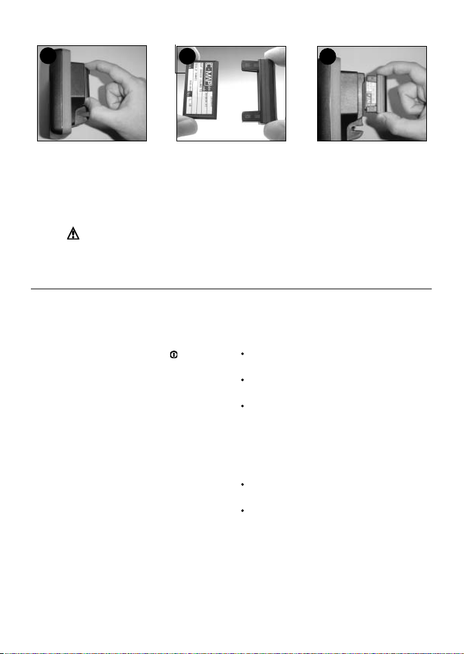
Changing the plug-in card
1
Gold contacts under here
2
2
Card
Holder
3
Turn the TRACKER off (see section 2-1).
Pull the card holder out of the TRACKER and
pull any card out of holder.
Put the card in its case.
Warning : Keep the holder in place i n the TRACKER at al l times to prevent
moisture from entering card compartment.
1-3 Removing and rep lacing the display unit
If the display unit is bracket mounted then the
display unit can easily be removed and replaced
for security or protection.
Removing the dis play unit:
1 Turn the TRACKER off by holding
display turns off.
2 Push the dust cover over the display unit.
3 Hold the display unit with one hand. Loosen
the knob on the mounting bracket and
carefully lift the unit of f the mounting
bracket.
4 The display unit has some cables plugged
into the back .
Unplug each black plug by turning the
locking collar a quar ter turn anticlockwise
and pulling the plug out.
If there is a gold plug, unscrew the locking
collar anticlockwise and pull the plug out.
5 Push the attached dust covers over the
exposed ends of the plugs to protect them.
6 Store the display unit in a safe place, such
as the TRACKER carry case or the optional
NAVMAN carry bag.
until the
Push new card into holder. Ensure the
gold contacts are on the outer edge and
underneath (see above).
Keep the card’s case.
Push card holder fully into TRACKER
Replacing the d isplay unit
1 Remove the dust covers from the plugs. Plug
the black plugs into their sockets on the back
of the display unit:
Match the colour on the end of the plug to
the colour of the nut on the socket.
Hold the plug against the socket and rotate
the plug until it slides into the socket.
Lock the plug in place by pushing the locking
collar towards the socket and turning it a
quarter turn clockwise.
Nothing will be damaged if a cable is
plugged into the wrong socket by mistake.
2 If the unit has a gold plug:
Plug it into its socket on the back of the
display unit.
Hand tighten the locking collar clockwise do not overtighten.
3 Hold the display unit in place on the
mounting bracket shaf t.
4 Adjust the tilt and rotation of the display for
best viewing and hand tighten the knob on
the mounting bracket. Remove the dust cover.
NAVMAN
TRACKER 5430/5430i Installation and Operation Manual
7
Page 8
2 Basic operation
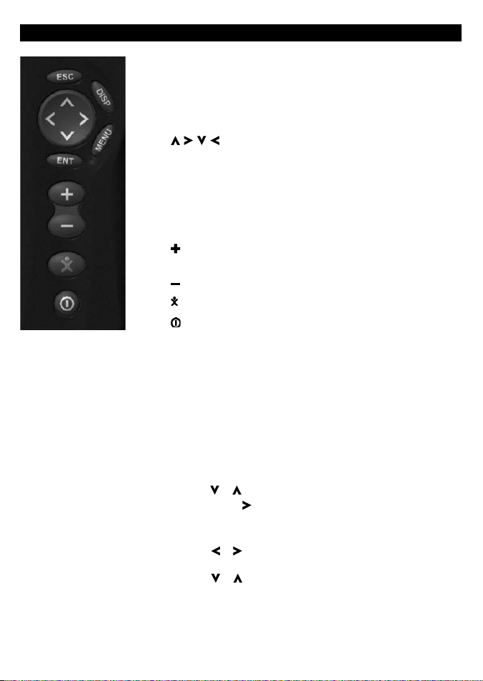
Overview of the keys
ESC Go back to an earlier menu or display. Any changes are
ignored.
DISP Show a menu of the main TRACKER displays. To go to a
display, select it from the menu (see section 2-2).
, , , Cursor keys, to move the cursor or the selection
highlight.
MENU Show a menu of the options for the current display. Press
MENU again to display the setup menu (see section 13).
ENT Start an action or accept a change or when displaying a
map press twice to create an instant waypoint at the boat
position (see section 9 -2-1).
Zoom in and display a smaller area of the chart in more
detail.
Zoom out and display a bigger area in less detail.
Man overboard (MOB, see section 2- 4).
Turn TRACKER on and off (see section 2-1); adjust the display
(see sec tion 2-3).
Keys
In this manual:
Press means to push the key for less than a second.
Hold means to hold the key down.
The internal beeper beeps when a key is pressed (to disable or
enable the beep, see section 13-1).
To select an item in a menu
The TRACKER is operated by selecting items from menus shown on
the display.
1 Press or to move the highlight to the item.
2 Press ENT or to select the item.
Change a number or word
To change a number or word on the display:
1 Press or to move the highlight to the digit or letter to
change.
Press or to change the digit or letter.
2 Repeat the above step to change any other digits or letters.
3 Press ENT to accept the change.
8
NAVMAN
TRACKER 5430/5430i Installation and Operation Manual
Page 9
2-1 Turning on and off / auto power
Auto power
If the TRACKER is wired for auto power (see
section 15-3), then the TRACKER automatically
turns on and off with the boat power, and can
not be turned on or of f manually.
Turning on manually
If the TRACKER is not wired for auto power, turn
the unit on by pressing
.
Start up
After the TRACKER has been turned on:
1 The unit displays a title display for a few
seconds, then beeps again and displays a
navigation warning.
2-2 The main displays
After you have turned the TRACKER on, it shows
the satellite display until the GPS receiver gets a
GPS fix, then displays the Char t. The Chart is the
display that you will normally use for navigation.
2 If necessary, adjust the display to be easy to
read (see section 2-3).
Read the warning and press ENT.
3 The satellite display is shown.
Either wait for the GPS receiver to start up
and the status to change from ‘acquiring’
to ‘GPS fix’ (see section 7).
Or press ESC.
4 The TRACKER chart is displayed (see section 3).
Turning of f manually
If the TRACKER is not wired for auto power, turn
the unit of f by holding down until the display
turns off.
To use one of the other main displays, press DISP
for the display menu and select a display to use.
To return to the char t display, press ESC.
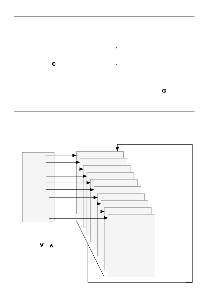
Display menu
Chart
Fuel
Data
Highway
Satellite
Tides
Waypoints
Routes
User card
About
Press DISP for
display menu
To select a display:
i press or to
highlight the display
ii press ENT to go to
the display
NAVMAN
TRACKER 5430/5430i Installation and Operation Manual
The main displays See:
Chart (navigation) Section 3
Fuel (fuel computer) Section 4
Data (numeric data) Section 5
Highway (boat path) Section 6
Satellite (GPS data) Section 7
Tides (tide chart) Section 8
Waypoints Section 9
Routes Section 10
User card Section 11
About Section 12
Press ESC to
return to
chart display
9
Page 10

2-3 Backlight and displ ay contrast
1 Press briefly to show the display controls.
2 The display and keys are backlit, with sixteen
brightness levels.
To change the backlight, press (dimmer)
or (brighter)
2-4 Man overboard (MOB)
The MOB feature saves the boat’s position and
then navigates back to this point. To do this:
1 Press
The TRACKER beeps four times and stores the
2 The TRACKER changes to the chart display,
The chart zooms in for accurate navigation.
3 If the autopilot output is off (see section 13-8)
If the autopilot output is on, the TR ACKER
.
boat’s position as a waypoint called MOB.
with the MOB waypoint at the centre of
the chart.
If the char t can not show the required small
scale, the TRACKER changes to plotter mode
(a white display with crosshatching, and no
chart details, see section 13-2).
the TRACKER immediately star ts navigating
back to the MOB waypoint.
asks if the autopilot is active. Select:
2-5 Al arms
When the TR ACKER detec ts an alarm condition,
it displays a warning message on the display, the
internal beeper sounds and any ex ternal beepers
or lights operate.
3 To change the display contrast:
i Press to choose Contrast.
ii Press or to adjust the contrast.
4 Press ENT to accept the new values.
No: The TRACKER immediately starts navigating
back to the MOB waypoint.
Yes : The TRACKER asks if the boat is to go to the
MOB waypoint. Select:
Yes : to immediately start navigating to the
MOB waypoint.
Warn ing: This might result i n a sudden
and dangerous turn.
No: to allow time to disengage the autopilot;
then use Goto to navigate back to the MOB
waypoint (see section 3-3) .
To cancel MOB or set another MOB.
1 Press again to display a menu.
2 Select an option from the menu.
Tip: The MOB waypoint remains on the chart
after the MOB has been cancelled. To delete the
MOB waypoint, (see section 9-2-5).
Press ESC to clear the alarm. The alarm will sound
again if the alarm condition occurs again.
The TRACKER has user settable alarms plus an
alarm for loss of GPS fix (see section 13-7)
2-6 Simulate mode
Simulate mode allows a user to become familiar
with the TRACKER off the water. In Simulate
mode, the data from the GPS receiver and
other sensors is ignored and the TRACKER
generates this data internally to simulate the
movement of the boat. Otherwise, the TRACKER
functions normally.
10
To see if the TRACKER is in Simulate mode, press
DISP and selec t Satellite. If it is in Simulate
mode, then it shows Simulate at the top lef t of
the display.
To start and s top Simulate mode, (se e section 13-1).
Warning : Never have Simulate m ode on
when the TRACKE R is navigating on t he water.
NAVMAN
TRACKER 5430/5430i Installation and Operation Manual
Page 11

2-7 Navi gatin g
The TRACKER has two ways of navigating, going
straight to a point or following a route.
Enter waypoints at points of interest before
starting to navigate (see section 9-2-1).
Tip: create a waypoint at the start of the trip
to navigate back to.
Goto: Going straig ht to a point
The TRACKER can navigate straight to a waypoint
or to any arbitrary point:
1 In the chart display, move the cursor to the
destination point to navigate to (see section
3-1-1).
2 Start navigating using the Goto function from
the chart menu (see section 3-3).
The chart, data and highway displays show
navigation data. The chart shows:
The boat position .
The destination point marked with a
circle.
The boat ’s plotted course to the
destination.
Two CDI lines, parallel to the boat’s
plotted course (see appendix C, CDI).
If the TRACKER is connected to an autopilot,
the TRACKER will send data to the autopilot
to steer the boat to the destination.
If the XTE alarm is enabled, an alarm will
sound if the boat deviates too much from its
intended course (to set the XTE alarm, see
section 13-7).
3 If the arrival radius alarm is enabled, then,
when the boat comes within the arrival
radius of the destination, an alarm will
sound to show that the boat has reached the
destination (to set the arrival radius alarm,
see section 13-7).
4 To stop the Goto, (see section 3-3).
Following a route
A route is a list of waypoints that the boat can
follow (see section 10).
1 To create waypoints before creating the
route, use the waypoints display (see section
9-2-1).
2 To create a route, go to the chart or routes
display (see section 10-2-1).
3 To start the route, see section (10-3-1).
The chart, data and highway displays show
navigation data. The chart shows:
The boat position .
The waypoint at the end of the current
leg marked with a circle.
The boat ’s plotted course along the leg.
Two CDI lines, parallel to the boat’s
plotted course (see appendix C, CDI).
If the TRACKER is connected to an autopilot,
the TRACKER will send data to the autopilot
to steer the boat to the destination.
If the XTE alarm is enabled, an alarm will
sound if the boat deviates too much from its
intended course (see section 13-7).
If the arrival radius alarm is enabled, then,
when the boat comes within the arrival radius
of the waypoint at the end of the current leg,
an alarm will sound (to set the arrival radius
alarm, see section 13-7).
4 The TRACKER stops navigating to the
waypoint at the end of the current leg and
start s the next leg of the route:
a When the boat comes within 0.025 nm of
the waypoint.
b Or when the boat passes the waypoint.
c Or if the waypoint is skipped (see section
10- 3-2).
5 When the boat has reached the final
waypoint, or to stop the boat following
the route at any time, cancel the route (see
section 10-3-3).
3 Chart
The chart display is the most important of the TRACKER’s displays, showing the chart, the boat ’s
position and course, and navigation data.
NAVMAN
TRACKER 5430/5430i Installation and Operation Manual
11
Page 12
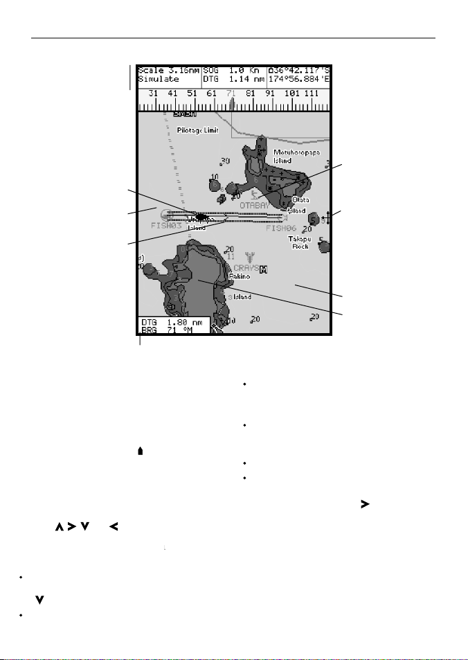
3-1 Chart display
A typic al chart display shows:
Data display. To turn
the data of f or on or to
change what data is
displayed, see sec tion
The chart. To change
the types of information
displayed, (se e sect ion
(see sec tion 3-1-1)
(see section 3-5)
Boat course and CDI
lines (see appendix
Boat is going to the
waypoint called
Distance and bearing of
cursor from boat.
3-1-8.
13-2 ).
Boat position
Boat track
C, CDI)
FISH06.
Chart is in cursor mode, press ESC to return to
centre on boat mode (see section 3-1-1)
3-1-1 Chart mode s
The Chart has two modes, centre on boat mode
and cursor mode. These are explained below.
Centre on boat mode
To switch to centre on boat mode in the chart
display, press ESC. The boat is at the centre of
the chart. As the boat moves through the water,
the chart automatically scrolls to keep the boat
in the centre of the chart. The cursor (see below)
is turned off.
Cursor mode
The keys , , and are called cursor keys.
To switch to cursor mode in the chart display,
hold down a cursor key. The cursor
moves away from the boat:
Press the key which points in the direction
that the cursor will move, for example press
to move the cursor down.
Press midway between t wo of the cursor keys
to make the cursor move diagonally.
12
appears and
Compass display
(see sec tion 3-1-4).
To turn the compass off
or on, see section 3-1-8.
Typical waypoint
(see section 9).
The cursor
(see section 3-1-1).
Sea
Land
Hold a cursor key down to make the cursor
move continuously across the display.
In Cursor mode:
The distance (+DST) and bearing (+BRG) of
the cursor from the boat are displayed at the
bottom, left corner of the display.
The chart does not scroll as the boat moves.
If the cursor reaches the edge of the display,
the chart will scroll.
For example, hold down to move the
cursor to the right side of the display and the
chart will scroll to the left.
3-1-2 Latitude and longitude
Latitude and longitude can be displayed at
the top of the chart. Normally the position is
the boat ’s position, and the latitude has a boat
symbol to show this:
NAVMAN
TRACKER 5430/5430i Installation and Operation Manual
Page 13
36° 29.637' S
175° 09.165
Degrees
Minutes, to 3 decimal places
If the cursor has been moved in the last ten
seconds, then the position is the cursor’s
position, and the latitude has a cursor symbol to
show this:
(about 2 m (6 ft) resolution)
Latitude
Longitude
' E
+ 36° 29.684' S
175° 09.201
Warning : When reading t he boat positio n,
make sure the posi tion is not the cursor
position.
' E
3-1-3 Chart scale
Press to zoom in and display a smaller area of
the chart in more detail. Press to zoom out and
display a bigger area in less detail.
The chart scale can be displayed (e.g. scale
= 8 nm, see below). The scale is the vertical
distance across the currently visible char t area.
For example if the scale is 8 nm then a portion
of chart eight nautical miles high is currently
displayed.
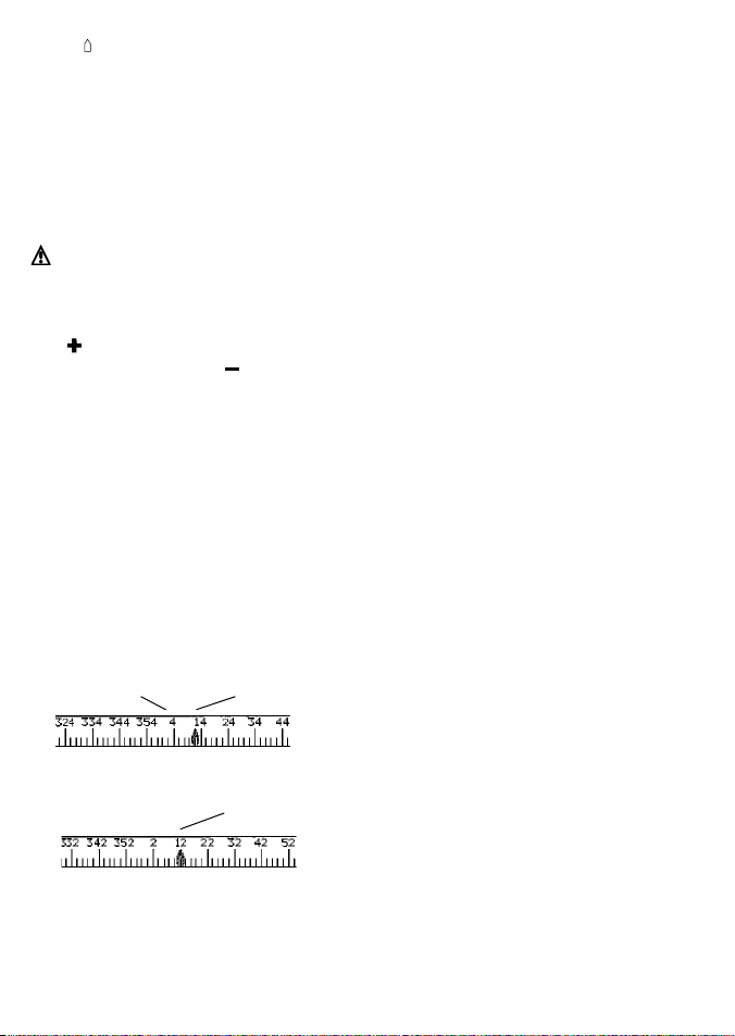
3-1-4 The compass
A compass can be displayed at the top of the
chart (see section 3-1-8).
When the boat is navigating to a point, the
compass shows the bearing to the destination
(BRG) in the middle and the boat ’s course over
ground (COG), for example here BRG is 4° and
COG is 12°:
Otherwise the compass shows the boat’s COG in
the middle, for example here COG is 12°:
BRG
COG
COG
3-1-5 Chart symbols
The chart will show symbols, such as waypoints
and chart symbols. When the cursor is placed
over a symbol for at least two seconds, a data
window appears at the bottom left of the display
with information about the symbol.
NAVMAN
TRACKER 5430/5430i Installation and Operation Manual
3-1-6 Chart information
To see stored data about a point on the chart (for
example, a chart symbol):
1 Move the cursor to that point on the chart.
2 Press MENU and selec t Chart info.
3 A menu of objects is displayed :
i Select an object to display.
ii Press ESC to return to the menu. Select
other objects.
iii Finally, press ESC to return to the chart.
3-1-7 Find nearby services
To find and display nearby services:
1 To see services near the boat’s position, press
ESC to switch to centre on boat mode. To
see services near a different point, move the
cursor to that point on the chart.
2 Press MENU and selec t Find.
3 Select the type of service. There are three
types of service:
Ports
A list of ports is displayed. Select the port
to display.
To search for a por t:
i Press MENU and selec t Find.
ii Enter some or all of the letters of the
port name. Press ENT.
Port ser vices
i Select the type of service to find.
ii A list of places with this service are
displayed. Select the place to display.
Tide stations
A list of tide stations is displayed. Selec t
the station to display. The chart redraws
with the tide station centred. To now
display a tide chart (see section 8) for the
station:
i Press MENU and selec t Chart info.
ii Select Tide height.
3-1-8 Change the data display and compass
display
Numeric data and a compass can be displayed at
the top of the chart display. To change these:
1 Press MENU and selec t Data header.
2 To turn the data display off or on:
i Select Data.
ii Select Off or On.
13
Page 14

3 To choose the size of the numbers:
i Select Size.
ii Select:
Small: displays three fields per line and
up to four lines.
Medium/Large: displays two fields per
line and up to four lines.
4 To change the data display:
i Select Data setup.
ii Change a data field:
a Press the cursor keys to highlight
the field.
3-2 Distance and bearing calculator
The distance and bearing calculator can plot a
course of one or several legs and to show the
bearing and length of each leg, as well as the
total distance along the course. The completed
course can be converted into a route.
To use the distance and bearing calculator:
1 Press ESC until the char t display is displayed.
Press MENU and select Distance.
2 Move the cursor to the start of the first leg. It
does not matter if this point is a waypoint or
not. Press ENT.
3 To add a leg to the course, move the cursor
to the end of the leg. It does not matter if this
point is a waypoint or not. The display shows
3-3 Goto
Goto is a simple way of navigating straight to
one point.
To start the Goto
1 Choose the point to go to:
To go to a waypoint or to any point on the
chart:
i Press ESC until the char t display is
displayed.
ii Move the cursor to the destination.
iii Press MENU and select Goto.
To go to a waypoint from the waypoints
display:
i Press DISP and selec t Waypoint s.
ii Press or to highlight the
destination waypoint.
14
b Press ENT to display a menu of the
data that can be shown in the field.
c Select the data to show in the field;
select None to leave the field empty.
iii Repeat the above step to set the other
data fields. Press ESC.
Tip: If less than four lines are used,
the numeric data will take up less of the
chart area.
5 To turn the compass display off or on:
i Select Compass.
ii Select Off or On.
6 Finally, press ESC to return to the chart
display.
the bearing and length of the leg, as well
as the total distance along the course.
Press ENT.
4 To remove the last leg from the course, press
MENU and selec t Remove.
5 Repeat the above two steps to enter the
whole course.
6 To save the new course as a route, press
MENU and selec t Save. This also saves any
new points on the course as new waypoints,
with default names. If necessary, edit the
route later (see section 10-2-2) and edit any
new waypoints later (see section 9-2-3).
7 Finally, press ESC to return to the chart
display.
iii Press MENU and select Goto.
Warning : Make sure the course does not
pass over land or dang erous waters.
2 The TRACKER starts navigating to the
destination (see section 2-7). The chart
shows:
The destination point marked with a
circle.
The boat ’s plotted course to the
destination.
Two CDI lines, parallel to the boat’s
plotted course (see appendix C, CDI).
To cancel a Goto
1 Press ESC until the char t display is displayed.
2 Press MENU and selec t Cancel goto.
NAVMAN
TRACKER 5430/5430i Installation and Operation Manual
Page 15

3-4 Projected course
If Projected course is turned on, then the
TRACKER will display the projected position
based on the course over ground (COG), speed
and a specified time. To turn Projected course on
and off and to set the time, see section 13-2.
Projected position
Boat’s projected course
Boat position
3-5 Tracks and tracking
Tracking records the boat ’s position to memory at
regular intervals, which can be:
Time intervals.
Or distance intervals.
The track of where the boat has been can be
displayed on the chart. The TR ACKER can display
one track while recording another.
To work with track s, (see section 13-5).
The TRACKER can store f ive tracks:
Track 1 can hold up to 20 00 points and is
intended to record the normal progress of the
boat.
Tracks 2, 3, 4 and 5 can hold up to 500 points
each and are intended to record sections to be
retraced accurately, for example entering a river
mouth.
Tip: Record the tracks in good conditions.
When recording is on and the track becomes full
then recording continues and the oldest points in
the track are deleted. The maximum length of a
track depends on the selected track interval: a small
interval will give a shorter, more detailed track and
a long inter val will give a longer, less detailed track,
as shown in these examples:
NAVMAN
TRACKER 5430/5430i Installation and Operation Manual
Time intervals
Inter val Track 1 Track 2, 3, 4 or 5
1 sec 33 minutes 8 minutes
10 sec 5.5 hours 1.4 hours
1 min 33 hours 8 hours
Distance intervals
Inter val Track 1 Track 2, 3, 4 or 5
0.01 20 5
1 2,000 500
10 20,000 5,000
The track lenghts are in the current distance
units, for example nm.
15
Page 16

4 Fuel display
To use the fuel display, the optional fuel kit must
be installed and the fuel data set up (see section
13- 4) .
To go to the fuel display, press DISP and select
Fuel.
The fuel display shows:
Used: The total fuel used since it was reset to 0
by the Clear Used command (see section 13-4).
Remaining: The amount of fuel remaining in the
fuel tank(s).
Flow: The fuel consumption. For twin engine
installations, the fuel flow for each engine is
shown separately. This is useful for checking that
both engines are under the same load.
Economy: The distance travelled per unit of fuel
used. The units are set by the units selec ted
for speed and fuel. Adjust throt tle and trim for
best economy. The bigger the number the bet ter
the economy.
Speed: Boat speed over ground.
Range: The estimated distance that the boat
is able to travel, based on fuel remaining and
current fuel consumption.
Warnings:
Fuel econ omy can change drastically depending on boat loa ding and sea conditions. Always
carry a dequate fuel fo r the journey plu s a sufficien t reserve.
Each time fuel is a dded or removed us e the fuel setup menu (see secti on 13-4) to record the
fuel or else fuel remaining and the low fuel alarm will be meaningless!
16
NAVMAN
TRACKER 5430/5430i Installation and Operation Manual
Page 17

5 Data display
The data display has six large numeric data fields.
To go to the data display, press DISP and select
Data.
Change what data is displayed
1 Press MENU and selec t Data setup.
2 Change a data field :
i Press the cursor keys to highlight the
field.
ii Press ENT to display a menu of the data
that can be shown in the field.
iii Select the data to show in the field; select
None to leave the field empty.
3 Repeat the above step to change other f ields.
4 Finally, press
display.
ESC to return to the data
6 Highway display
The highway display has a bird’s eye view of the
boat’s course to a destination:
To go to the highway display, press DISP and
select Highway.
Warning : The highway display does
not show land, dangerous waters or chart
symbols.
The highway display shows:
To change what data is displayed, see over.
Boat’s plotted course to destination.
CDI lines, parallel to the boat’s plotted course
(see appendix C, CDI). The CDI lines are like
a highway over the water where the boat
NAVMAN
TRACKER 5430/5430i Installation and Operation Manual
Six numeric data fields.
Destination waypoint.
Boat position is at the bottom,
centre of the display.
will move.
CDI scale
17
Page 18

Change the numeric d ata display
1 In the highway display, press MENU and
select Data setup.
2 Change a data field :
i Press the cursor keys to highlight the
field.
7 Satellites
GPS worldwide navigation
The US Government operates the GPS system.
Twenty-four satellites orbit the earth and
broadcast position and time signals. The
positions of these satellites are constantly
changing. The GPS receiver analyses the signals
from the closest satellites and calculates
exactly where it is on earth. This is called the
GPS position.
The accuracy of the GPS position is typically
better than 5 m (16.4 ft) for 95% of the time. A
GPS antenna can receive signals from the GPS
satellites when it is almost anywhere on earth.
DGPS
A DGPS system uses correction signals to
remove some of the errors in the GPS position.
The TRACKER can use one of two types of DGPS
system:
WAAS and EGNOS DGPS
WAAS and EGN OS are two satellite based
DGPS systems. The co rrection signals are
broadcast by satellites and are received by
the TRACKER ’s standard GPS antenna . The
accuracy of the corrected GPS position is
typic ally better than 5 m (16 ft) for 95% of
the time.
WAAS covers all of the USA and most of
Canada. EGNOS will cover most of Western
Europe.
Differential beacon DGPS
Differential beacons are land based radio
transmitters that broadcast correction signals
that can be received by a special receiver on
the boat. Differential beacons are usually
only installed near ports and important
waterways, and each beacon has a limited
range. The accuracy of the corrected GPS
position is typically bet ter than 2 to 5 m
(6 to 16 ft).
18
ii Press ENT to display a menu of the data
that can be shown in the field.
iii Select the data to show in the field; select
None to leave the field empty.
3 Repeat the above step to change other f ields.
4 Finally, press ESC to return to the highway
display.
GPS antennas
• The TRACKER 5430i has a built in GPS antenna.
• The TRACKER 5430 must be used with an
external GPS antenna. It is recommended to
use the GPS antenna supplied.
• The TRACKER can apply the WAAS and
EGNOS DGPS corrections to any GPS antenna.
• Fit an optional dif ferential beacon DGPS
antenna to give enhanced accuracy within
range of land based differential beacons
in areas where WAAS or EGNOS are not
available. Such a DGPS antenna has both a
GPS receiver and a beacon receiver, and it
automatically applies the beacon correction
to the GPS position.
• The TRACKER can use GPS satellite data from
a optional compatible instrument or antenna
connected by NavBus or NMEA (see sections
14 and 15-3). In this case, the TRACKER does
not need its own antenna.
To configure the TRACKER for different antenna
options, see section 13-3. For more information,
contact your NAVMAN dealer.
The TRACKER has a sensitive 12-channel receiver
built in, which track s signals from all GPS
satellites visible above the horizon and uses
measurements from all satellites more than 5°
above the horizon to calculate the position.
Start up
Each time a GPS receiver is turned on, it normally
takes about 50 seconds before it outputs the f irst
position. Under some circumstances it will take
up to two minutes or longer.
NAVMAN
TRACKER 5430/5430i Installation and Operation Manual
Page 19

7-1 Satellite display
The satellite display has information about the
GPS satellites and GPS position.
To go to the satellite display, press DISP and
select Satellite.
When the TR ACKER is turned on, the satellite
display is shown automatically while the GPS
antenna starts up.
The sate llite display
shows:
Time & date from
GPS satellites. Time is
local time (UTC (GMT )
plus local offset, see
section 13-10).
HDOP: The error in
the GPS position
caused by satellite
geometry. A low
value indicates a
more precise fix,
a high value a less
precise fix.
Signal strengths of
up to twelve visible
GPS satellites. The
higher the bar the
stronger the signal.
8 Tides display
The tides display shows tide information at a tide
station for the selected date.
To go to the tides display for the tide station
nearest to the boat, press DISP and select Tides.
To go to the tides display for any tide station:
1 From the char t display, press MENU and
select Find.
2 Select Tide stations.
3 A list of tide stations are displayed. Select the
tide station to display. The chart redraws with
the tide station centred.
Status of GPS antenna, for
example Acquiring, GPS
fix, No GPS. If the unit is in
Simulate mode it displays
Simulate (see section 2-6).
Positions of visible GPS
satellites:
Outer circle is horizon
Inner circle is 45°
elevation
Centre is directly
above
North is at top of
display
If the boat is moving, COG
is a line from centre.
Boat position.
4 Press MENU and selec t Chart info.
5 Select Tide height.
Choosing the date of the tide char t
1 Press MENU.
2 Select Toda y, Next day or Prev day.
To choose a different date from these, select
Set date, edit the date, press ENT.
NAVMAN
TRACKER 5430/5430i Installation and Operation Manual
19
Page 20

The tide s display shows da ta for the chose n date:
Tide station name
Distance from boat
Current time
Chosen date for display
Tide chart
Night
Dawn
Day
Tide height
Time cursor.
Press or to move
cursor sideways.
Time of cursor
Tide height at that time.
Height and time of highest high water and lowest low water on tide chart.
9 Waypoints
A waypoint is a position of interest that is saved
by the TRACKER, for example a fishing spot or
a point on a route. The TRACKER can have up
to 1000 waypoints. A waypoint can be created,
changed or deleted. A waypoint has:
A name (up to eight characters).
An icon showing what kind of waypoint it is.
The available icons are:
Moon phase for moon at
the current time on the
chosen date.
Night
Dusk
Day
Tide height cursor. Press
or to move cursor
up and down. Height of
cursor.
Time of day, 0 to 24 hrs
Times on selected date.
A position.
A type:
Normal: A normal waypoint can be
navigated to or included in a route.
Danger: A danger waypoint is a point
to avoid. If the boat comes within the
danger radius of a danger waypoint the
unit can sound an alarm.
(see sec tion 13-7).
A display option:
Controls how the waypoint is displayed when
the Waypo ints setup option is set to Selec ted
(see sec tion 13-2):
Off: The waypoint is not displayed.
Icon: The waypoint icon is displayed.
I+N (Icon and Name): The waypoint icon
and name are displayed.
20
NAVMAN
TRACKER 5430/5430i Installation and Operation Manual
Page 21

If there are many waypoints, use this feature
to select which waypoints are displayed on
the chart.
9-1 Waypoints display
To go to the waypoints display, press DISP and
select Waypoi nts (see right).
The waypoints display is a list of the waypoints
that have been entered, each with waypoint
symbol, name, latitude and longitude, distance
and bearing from the b oat, type and display
option.
9-2 Managing waypoints
Warning : Do not create a navi gation
waypoint on land or i n dangerous water.
9-2-1 Creating a new waypoint
Creating and edi ting a new waypoint from
the chart disp lay
1 To create a waypoint at the boat position,
press ESC to centre on the boat.
To create a waypoint at a different point,
move the cursor to that point on the chart.
2 Press ENT and select save, or press MENU
and select New waypoint.
3 A new waypoint, with the default name and
data is created.
4 Change the waypoint data if necessary (see
section 9-2-7). Select Save.
Creating a new waypoint from any displ ay
Press ESC on any display to switch to the chart.
Follow the steps as described above.
To change the default data, (see sec tion 9-2-3).
Note: If a GPS fix hasn' t been acquired, a wayp oint
will be created a t the cursor position instead o f the
boat position.
Creating a new waypoint from the waypoints
display
1 In the waypoints display, press MENU and
select Create.
2 A new waypoint, with a default name and
data, is created at the boat position.
3 Change the waypoint data if necessary (see
section 9-2-7). Select Save.
Note: Waypoints can a lso be created when a route
is created (see sec tion 10-2-1).
NAVMAN
TRACKER 5430/5430i Installation and Operation Manual
Note: the other cho ices for the “Waypoi nts”
setup optio n are “Hide all” (no wa ypoints are
displayed o n the chart) and “Sho w all” (all the
waypoint s are displayed on the char t) (see
section 13-2).
9-2-2 Moving a waypoint
Moving a way point from the chart di splay
1 In the chart display, move the cursor to the
waypoint to move.
2 Press MENU and selec t Move.
3 Move the cursor to the new position and
press ENT.
Moving a way point from the waypoint s
display
To move a waypoint from the waypoints display,
edit the waypoint (see section 9-2-3) and change
the latitude and longitude.
9-2-3 Editing a waypoint
Editing a waypoi nt from the char t display
1 In the chart display, move the cursor to the
waypoint to edit.
2 Press MENU and selec t Edit.
21
Page 22

3 Change the waypoint data (see section
9-2-7). Select Save.
Editing a waypoi nt from the waypoi nts
display
1 In the waypoints display, press
highlight the waypoint to edit. Press MENU
and select Edit.
2 Change the waypoint data (see section
9-2-7). Select Save.
or to
9-2-4 Displaying a waypoint on the chart
This goes to the chart display, and shows the
selected waypoint at the centre of the display.
1 In the waypoints display, press or to
highlight the waypoint to display. Press
MENU and selec t Display.
2 The TRACKER switches to the chart display,
with the selected waypoint at the centre of
the chart.
9-2-5 Deleting a waypoint
A waypoint can not be deleted if the boat is
navigating to it or if the waypoint is used in more
than one route. A waypoint that is used in one
route can be deleted.
Warning when a waypo int is deleted from
a route, c heck that the changed r oute does
not cros s land or dangero us waters.
10 Routes
A route is a list of waypoints that the boat can
navigate along. Routes can be created, changed
and deleted.
The TRACKER can have up to 25 routes. Each
route can have up to 50 waypoints. A route can:
Start and stop at the same waypoint .
Include waypoints more than once.
10-1 Routes display
The routes display is a list of the routes that
have been entered, each with route name, start
waypoint, end waypoint, number of legs and
total distance.
To go to the routes display, press DISP and select
Routes.
Delet ing a waypoint from the chart disp lay
1 In the chart display, move the cursor to the
waypoint to delete.
2 Press MENU and selec t Delete.
3 Select Yes to confirm.
Del eting a way point f rom the waypoint s
display
1 In the waypoints display, press or to
highlight the waypoint to delete. Press MENU
and select Delete.
2 Select Yes to confirm.
9-2-6 Deleting all waypoints
1 In the waypoints display and press MENU
and select Delete all.
2 Select Yes to confirm.
9-2-7 Changing a waypoint’s data
To change the waypoint data when it is displayed
in a window:
1 Select the data to change.
Press ENT.
Use the cursor keys to change the data.
Press ENT.
2 If necessary, repeat the above step to change
other data.
3 Select Save.
The TRACKER can navigate along a route in
either direction. Waypoints on the route can
be skipped.
Routes are a powerful feature when the TRACKER
is connected to an autopilot, allowing the vessel
to be automatically guided along the route.
Warning : Make sure that ro utes do not
cross la nd or dangerous w ater.
22
NAVMAN
TRACKER 5430/5430i Installation and Operation Manual
Page 23

10-2 Managing routes
Warning : After creating or changing a
route, d isplay the route on the chart and
check t hat it does not cross land or dangerous
water.
10-2-1 Creating a new route
A. Creat ing a new route fro m the chart display
While creating the route:
Press or to change the range; scroll the
chart by moving the cursor to the edge of
the chart.
A data box at the top, left of the display
shows the route name and total distance. If
the cursor is near a leg, it shows the length
and bearing of the leg as well.
The legs of a route must start and end at
waypoints. If a leg does not start or end at an
existing waypoint then a new waypoint will
be created automatically (to change the new
waypoint data, see section 9-2-7).
1 In the chart display, press MENU and selec t
New route.
2 The route is given a default name:
i Change the name if necessary.
ii Select Ok.
3 To enter the first leg of the route:
i Move the cursor to the star t of the route
and press ENT.
ii Move the cursor to the end of the first leg
and press ENT.
4 To add a waypoint at the end of the route:
i Press ENT.
ii Move the cursor to where the new route
waypoint will be.
iii Press ENT.
5 To insert a waypoint in the route:
i Move the cursor to the chosen leg to
insert the waypoint.
ii Press MENU and select Insert.
iii Move the cursor to where the new route
waypoint will be.
iv Press ENT.
6 To move a waypoint in the route:
i Move the cursor to the waypoint to move.
ii Press MENU and select Move.
iii Move the cursor to where the waypoint
will be.
iv Press ENT.
7 To remove a waypoint from the route:
i Move the cursor to the waypoint to
remove from the route.
ii Press MENU and select Remove. The
waypoint is removed from the route, but
the waypoint is not deleted.
8 Repeat this process until the route is finished.
Review the route and check that the route
does not cross land or dangerous water.
Then press ESC.
Or, to delete the route that is being created:
i Press MENU and select Delete.
ii Select Yes to confi rm.
Tip: The distance and bearing calculator can
also be used to enter a course and save it as a
route (see section 3-2).
B. Creating a new r oute from the ro utes display
1 In the routes display, press MENU and select
Create.
2 A new route, with a default name and no
waypoints, is displayed.
3 To change the route name:
i Select the route name at the top of the
display and press ENT.
ii Change the name if necessary.
iii Press ENT.
NAVMAN
TRACKER 5430/5430i Installation and Operation Manual
23
Page 24

4 To insert a waypoint in the route:
i Select where the waypoint will be:
To insert the f irst waypoint in a new
route, select Leg 1.
To insert a waypoint at the end of the
route, select the unused leg at the
end of the list of waypoints.
Otherwise, select the waypoint to
insert the new waypoint in front of.
ii Press ENT. A list of waypoints is displayed.
Select the waypoint to use.
As waypoints are inserted, the distance and
bearing of each leg is shown automatically. If
the route has more waypoints than will fit on
the display, press or to see them.
5 To remove a waypoint from the route:
i Select the waypoint to remove.
ii Press MENU and select Remove.
6 Repeat this process until the route is finished.
7 Press ESC.
8 Display the route on the chart (see section
10-2-3) and check that the route does not
cross land or dangerous water.
10-2-2 Editing a route
Editing a route from the chart
1 In the routes display, select the route to edit.
Press MENU and select Edit on char t.
10-3 Navigating a r oute
10-3-1 Starting a route
To start the boat navigating along a route:
1 In the routes display, press or to
highlight the route to use. Press MENU and
select Start.
2 The TRACKER asks for the direction to
traverse the route.
Select For ward (the order the route was
created) or Reverse.
3 It displays a chart with the route marked and
start s navigating from the start of the route.
24
2 The selected route is displayed on the chart,
with a circle around the f irst waypoint.
3 Edit the route as described in section 10-2-1
A, starting at step 4.
Editing a route from the routes di splay
1 In the routes display, press or to
highlight the route to edit. Press MENU and
select Edit.
2 The selected route is displayed: the route
name and a list of the waypoints.
3 Edit the route as described in section 10-2-1
B, starting at step 3.
10-2-3 Displaying a route on the chart
This goes to the chart display, and shows the
selected route at the centre of the display.
1 In the routes display, press or to
highlight the route to display. Press MENU
and select Display.
2 It returns to the chart display, with the
selected route displayed.
10-2-4 Deleting a ro ute
1 In the routes display, press or to
highlight the route to delete. Press MENU
and select Delete.
2 Select Yes to confirm.
10-2-5 Deleting all routes
1 In the routes display, press MENU and select
Delete all.
2 Select Yes to confirm.
10-3-2 Skipping a waypoint in a route
To skip a waypoint when the boat is navigating
along a route:
In the chart display, press MENU and select
Skip.
The TRACKER start s navigating straight towards
the next waypoint on the route.
Warning : Skipping a wayp oint with the
autopilot on mig ht result in a sudden cour se
change.
10-3-3 Cancelling a r oute
To stop the boat navigating along a route:
In the chart display, press MENU and select
Cancel route.
NAVMAN
TRACKER 5430/5430i Installation and Operation Manual
Page 25

11 User card display
A C-MAP™ user card is an optional plug-in card
that can store data files (see section 1-2). There
are three t ypes of files: waypoints, routes or a
track.
Note: The older 5 vol t cards are not supported .
To go to the user card display, press DISP and
select User card.
The user card display has:
File list
A list of the files on any user card in the TRACKER.
Waypts, Routes
The number of waypoints and routes
currently in the TRACKER.
Track 1 to Track 5
The number of points in tracks 1 to 5
currently in the TRACKER.
Note:
To save TRACKER data onto th e user card, use
the Save comma nd (see below).
Data stored on t he user card and shown on
the file lis t is not available to be used by th e
TRACKER until l oaded into the TRACKER wi th the
LOAD command (see be low).
Saving TRACKER data to the user card
This saves all the TRACKER ’s waypoints, all the
TRACKER’s routes or one of the TRACKER’s tracks
to one file on the user card.
1 Press MENU and selec t Save.
2 Select Waypts , Routes or Trac ks .
3 For Trac ks , select the track number to save.
4 The new file is created. Change the name if
required. The new f ile appears in the f ile list.
Loading data from t he user card to the
TRACKER
This loads one file from the user card to the
TRACKER:
A waypoints file : The new waypoints are
added to any existing waypoints in the
TRACKER. If a new waypoint has the same
name as an existing waypoint but has
different data, the TRACKER displays both
waypoints. Select:
Skip: Do not load the new waypoint.
Replace: Load the new waypoint and
replace the existing one.
Skip all: Do not load any new waypoints
which have the same names as existing
waypoints.
Rplc. all: Load all new waypoints
which have the same names as existing
waypoints; the new waypoints replace
the existing waypoints.
A routes file: The new routes are added to
any existing routes in the TRACKER . If a new
route has the same name as an existing route
but has dif ferent data then the TRACKER ask s
which route to keep.
A track file: The new track will replace the
existing track in the TRACKER.
To load a file to the TRACKER:
1 Select the file to load.
2 Press MENU and selec t Load.
NAVMAN
TRACKER 5430/5430i Installation and Operation Manual
25
Page 26

Deleting a file from the use r card
1 Select the fi le to delete.
2 Press MENU and select Delete.
3 Select Yes to confi rm.
Reading the file information
This reads the file names from the user card and
displays them. Reading does not load any file
data into the TRACKER.
1 Press MENU and select Card.
2 Select Read.
12 About display
To go to the about display, press DISP and select
About.
The about display shows:
The software version and date.
The world chart version.
Any card fitted.
The number of waypoints, routes and tracks
in the TRACKER.
Wiring information for the TR ACKER
connectors.
In the unlikely event of having to contact a
NAVMAN dealer for service, quote the software
version number and date.
Formatting the us er card
Formatting prepares a user card for use. Format
the card if there is an error message saying that
the card is not formatted. Any data f iles on the
card are deleted.
1 Press MENU and select Card.
2 Select Format.
3 Select Yes to confi rm.
Sorting the file names
This sor ts the displayed file names.
1 Press MENU and selec t Sort.
2 Select sort by Name, Ty pe or Time.
13 Setup menu
The TRACKER has a number of advanced
navigation features which are set up through the
setup menu. We recommend that you become
familiar with the operation of the unit using the
26
default settings before making any changes to
the data in these menus.
To display the setup menu, press MENU until the
setup menu is displayed.
NAVMAN
TRACKER 5430/5430i Installation and Operation Manual
Page 27

Setup menu map, with factory de fault settings in brac kets
System Language (English)
Rotation (North up) Backlight
Projected course (Off ) Keybeep (On)
CDI scale (0.1 nm) Factory reset
Chart Plotter mode (Off )
Map datum (WGS84)
NMEA datum off set (Off )
Map shift (None)
Waypoints (Selected)
Anticlutter (Off )
Lat.Lon Grid (Off )
Boundaries (On) Bathymetric Lines (On)
Names (On) Spot soundings (On)
Attention Areas (On) Bath & Sndgs Min: (0 m)
Water Features (On) Bath & Sndgs Max: (15 m)
Water depth
Lights (On)
Nav-Aids (Int)
Land Features (On)
GPS GPS source (Internal)
Tank full DGPS Source (None)
Set remaining (0) Restart GPS
Clear Used Static Navigation (Off )
Fuel Tank size (0) Speed Filter: (5)
Num Engines (0) Course Filter: (4)
Fuel cal
Flow fi lter (5)
Track Record (1)
Reset trip dist Display (1)
Logs Reset total dist Plotting Interval (Distance)
Trip dist Distance (0.1 nm)
Total dist Time (10 seconds)
Memory used
Arrival radius (Off ) Delete track
Anchor alarm (Off )
Alarms XTE (Off ) Distance (nm)
Danger (Off ) Speed (kn)
Low fuel (Off ) Depth (fa)
DGPS (On) Fuel (litres)
Units Compass (°M)
NMEA out Temperature (°C)
NMEA data Wind (true)
Comms Lat/Lon d.p’s (3)
NavBus (Off )
NavBus group (0) Local off set (0)
Time Time format (24 hour)
Simulate (Off ) Date format (dd/MMM/yy)
Mode (Normal)
Simulate Speed (1 kn)
Heading (0°M)
Setup menu
Route
NAVMAN
TRACKER 5430/5430i Installation and Operation Manual
27
Page 28

13-1 System setup
Language
Select the language for the displays. The options
are English, Italian, French, German, Spanish,
Dutch, Swedish, Portuguese Finnish and Greek.
Backlight
Select the backlight intensity and the LCD
contrast levels.
To change the d efault settings:
i Press
ii Press
iii Press ENT
or
select between Backlight and Contrast.
to
or
to select the desired level.
Keybeep
Enable or disable the b eep when a key is pressed.
13-2 Chart setup
Rotation
The options for char t rotation are:
North up: North is always at the top of the
chart display.
Tra ck up : The chart is rotated so that the
boat direction is to the top of the display.
This option is useful for navigating narrow
harbours or rivers. The TRACKER asks for a
course deviation; this is how much the boat
direction needs to change to make the chart
redraw.
Tip: If the char t redraws too
frequently, increase the course deviation
setting.
Course u p: This option is only available if the
boat is navigating to a destination. The chart
is rotated so that the plotted course to the
destination is vertical.
Projected course
The TRACKER can estimate the course after a
given time, based on the current speed and
heading (see section 3-4). The options are 2
minutes, 10 minutes, 30 minutes, 1 hour, 2 hours
or Off.
Factory reset
Resets all the TRACKER setup menu data back
to the factory default settings as shown on the
setup menu map. Any waypoints, routes or tracks
are not deleted.
After the reset, the TRACKER displays an
installation menu of setup data:
1 Select the language to use.
2 Change the setup data if necessar y:
i Select the data item to change.
ii Use the cursor keys to change the data.
iii Press ENT.
3 When the setup data is correct, press ESC.
CDI Scale
The CDI Scale is described in appendix C, CDI.
The options are 0.05, 0.1, 0.2, 0.5, 1.0, 2.0, 4.0 and
10.0 distance units.
Plotter mode
Occasionally it is desirable to use a chart scal e
which is not available on a chart card. Examples
are:
To zoom in to a small scale to track ver y small
boat movements.
If there is no detailed chart for an area, for
example when crossing an ocean.
If Plotter mode is On, then if the chart zooms to
a scale which is not available, the TRACKER will
enter plotter mode and will only display the boat
position and track (if enabled). Chart and map
information will no longer be displayed and the
display is white with black crosshatch lines.
For normal use, turn Plot ter mode to Off.
28
NAVMAN
TRACKER 5430/5430i Installation and Operation Manual
Page 29

Map datum and map shift
Satellite derived positions on the TRACKER
are based on a worldwide reference (datum)
known as WGS84. Most paper char ts are based
on WGS84. However, some paper charts are
not based on WGS84, which results in an offset
between a position on the TRACKER and the
same position plot ted on the paper chart.
To match the TRACKER’s positions with a local
chart that is not based on WGS84:
Either selec t Map datum and select the datum
for the local chart. See appendix A for a list of
the available datums. WGS84 is the default
datum, and the datum most commonly used
on paper charts.
Or, if the correct datum is not available, retain
the WGS84 datum and apply a map shif t.
(see below).
NMEA datum off set
If you select a map datum other than WGS 84,
the map datum offset can be applied to latitude
and longitude coordinates sent on the TRACKER
NMEA output:
Off: Latitude and longitude coordinates
displayed on any NMEA repeater do not
match the coordinates on the TRACKER.
Latitude and longitude coordinates
broadcast on any NMEA VHF transmitter
will be the same as the coordinates on a
WGS 84 chart.
On: Latitude and longitude coordinates
displayed on any NMEA repeaters match
the coordinates on the TRACKER. However,
latitude and longitude coordinates broadcast
on any NMEA VHF transmitter will be slightly
offset from coordinates on a WGS 84 chart.
Map shift
Map shift is a correc tion applied to the TR ACKER’s
positions so that they match a chart ’s positions.
Warning : Map shift is fo r eliminating
minor of fsets. It should not b e used if the
correc t datum is available. Use map shif t
with caution : incorrect applicat ion will cause
incorrect boat positions.
Set map sh ift
1 Move the boat to a k nown point on the char t,
for example a marina b erth.
2 In the Chart setup menu, select Map shif t.
3 Move the cursor to the position on the chart
where the boat actually is.
4 Press ENT to set the new map shift. The boat
will now be displayed at its actual location.
Clear map shift
Clearing the map shif t removes any map shift
from the TR ACKER’s positions.
1 In the Chart setup menu, select Map shif t.
2 Press MENU and selec t Clear.
Waypo ints
Controls how waypoints are displayed on the
chart. The options are:
Hide all: No waypoints are displayed. (
except for waypoints on any selec ted route).
Show all: All waypoints are displayed.
Selected: Waypoints with their display
option set to Icon or I+N (Icon and Name) are
displayed (see section 9).
Chart display options
The other chart setup options allow an extensive
range of chart card features to be shown.
Configure the most useful display format.
Bathymetric Lines and so undings
Chart cards contain a large amount of spot
sounding and depth contour data. This can be
selectively displayed by turning Bathymetric
Lines and Spot Soundings on, then selec ting
the range to display with Bath and Sndgs Min
and Max.
Attenti on Areas
Areas of importance, such as restricted
anchorages and shallow areas, are highlighted as
Attention Areas. The options are :
On: displays attention area boundaries and
information icons
Off: does not display attention area
boundaries or information icons
Note: In some early chart cards the information
are inactive.
icons
.
.
NAVMAN
TRACKER 5430/5430i Installation and Operation Manual
29
Page 30

13-3 GPS setup
GPS Source
There are three options:
• Internal: For the TRACKER 5430i, use the
internal GPS antenna and receiver. For
TRACKER 5430, use the internal GPS receiver
and an external GPS antenna plugged into
the gold connector on the TRACKER .
• NMEA: Use an external GPS or DGPS source
connected via NMEA (see section 14).
• NavBus: Use an external GPS or DGPS source
connected via NavBus (see section 14).
DGPS Source
Enables or disables the satellite based DGPS
correction (see section 7). The options are None
or WAAS/EGNOS. Do not enable WAAS/EGNOS
outside their coverage areas or the accuracy of
the position might be degraded.
WAAS covers all of the USA and most of Canada.
To use WAAS, the GPS antenna must have a clear
view of the sk y towards the equator. EGNOS will
cover most of Western Europe.
Restart GPS
Restar ts the internal GPS receiver for ser vicing
or troubleshooting. The GPS receiver takes up
to three minutes to restart. The satellite display
shows the status of the GPS receiver.
(see sec tion 7).
13-4 Fuel Setup
To use these fuel features first purchase and
install the optional single or t win engine fuel kit.
Whenever fuel is added or removed from the
tank, use this menu :
If the tank is filled, selec t Tank Full.
If the tank is partly f illed or fuel removed:
1 Before adding or removing the fuel, go to
the fuel display and note how much fuel
is in the tank.
2 Note how much fuel is added or removed.
3 Calculate how much fuel is now in the
tank by adding or subtracting the two
figures.
4 Select this menu and enter how much
fuel is now in the tank in Set Remaining.
Warning : Do this each time fuel is a dded or
removed or else fue l remaining and t he low
fuel alarm will be meaningless !
30
Static Navigatio n
The displayed speed and course become erratic
when the boat stops. Turn Static navigation On
to display speed and course as zero when the
boat is stopped.
Speed and Course Filter
Waves and wind cause the boat position, speed
and course to f luctuate slightly. To give stable
readings, the TRACKER calculates these values
by taking several measurements and averaging
them.
A lower value averages measurements over
a shorter period of time. This gives the most
accurate value but has the most fluctuations.
A higher value averages measurements over
a longer period of time. This gives the most
stable value but will ignore some true speed
changes.
Set the Speed and Course filters to the lowest
values which give stable readings. The range of
each filter is 1 to 60 seconds or Off (0).
Tan k Full
Select Tank ful l each time the tank is filled full.
When asked for confirmation, Select Ye s.
Set Remaining
Enter the amount of fuel now in the tank af ter it
has been partly filled or fuel has been removed.
Clear Used
Select Clear Used to set Used (the amount of fuel
used) to zero. Do this to restart measuring the
amount of fuel used.
When asked for confirmation, Select Ye s.
Tan k Size
Enter the capacity of the fuel tank.
Num Engines
Set the numb er of engines to None, One or Two.
If None is selected the fuel features are turned off.
NAVMAN
TRACKER 5430/5430i Installation and Operation Manual
Page 31

Fuel Ca l
Without calibration the error in fuel
measurements can be up to ± 10%. Calibration
can reduce the error substantially. For twin
engine installations calibration of each
transducer is required.
Calibrating the fuel transducer requires accurate
measurement of the fuel used. This is easiest with
a small por table tank. It should be noted that due
to air pocket s, it is very difficult to fill under floor
tanks to the same level twice. At least 15 litres (4
US gallons) should be used to ensure an accurate
calibration. (The more fuel used, the more
accurate the calibration will be. ) Each transducer
in a twin engine installation must be calibrated
separately. This may be done at the same time
with two portable tanks, or at dif ferent times
using one tank at a time.
The procedure is:
1 Select Clear Used to set Used to zero.
2 Connect the measurement tank(s) to the
engine(s) via the fuel transducer(s).
3 Run the engine(s) at normal cruising spe ed
until at least 15 litres (4 US gallons) is indicated
(30 litres [8 US g allons] for twin en gines).
13-5 Track setup
Tracking records and displays the boat ’s course
on the chart (see sec tion 3-5).
Record
Off: The TRACKER stops recording a track.
1 to 5 (select a track number): The TRACKER
starts recording the boat ’s course into the
selected track.
Display
Off: No track is shown on the chart.
1 to 5 (select a track number): The selec ted
track is shown on the char t.
Plotting Interval
The options are Distance or Time.
Distance
Select the distance plotting interval: 0.01, 0.05,
0.1, 0.5, 1.0, 2.0, 5.0 or 10.0 distance units.
4 Check the actual amount of fuel used per
engine. The easiest way to do this is to ref ill
the tank(s) to the original level(s) and record
the value (s) shown on the fuel dispenser.
5 Select Fuel Cal. The amount of fuel that the
TRACKER has measured is displayed. Change
the number to the actual fuel amount used.
(Repeat for the other engine in a twin engine
installation).
Flow Filter
Normally engines do not draw fuel from the tank
at a steady rate. To give a stable fuel flow reading,
the TRACKER calculates the flow values by taking
several measurements and averaging them. The
flow filter sets the period over which the fuel
flow is averaged, and can be set from 1 to 180
seconds or Off.
Set the flow filter to the lowest value which give
a stable f low. Usually a value of 10 to 15 seconds
will give a satisfactory result for carburettor
engines. Fuel injec ted engines may require a
larger value.
This setting affects the Flow rate and Economy
displays. It does not affec t the fuel used
measurement.
Time
Select the time plotting interval: 1, 5, 10 or 30
seconds or 1 minute.
Memory used
The percentage of memory used in the track
being recorded.
Tip: Use the user card display to check the
number of points recorded in each track (see
section 11).
Send track
Sends track data on the serial port.
Delete track
1 Select the track number to delete (1 to 5).
2 Select Yes to confirm.
The data in the selected track is deleted.
NAVMAN
TRACKER 5430/5430i Installation and Operation Manual
31
Page 32

13-6 Logs setup
The values can be changed independently of
each other. These log values are saved when the
unit is turned off.
The TRACKER has two distance logs.
Tri p dis tanc e:
The distance travelled since log was reset.
Total dista nce:
The distance travelled since total log was reset.
Reset trip dist
This resets the trip distance to zero.
Reset to tal dist
This option resets the total distance to zero.
13-7 Alarms setup
For alarm operation, see sec tion 2-5. To turn off
an alarm which is sounding, press ESC.
Arrival radius alarm
When the arrival radius alarm is enabled, an
alarm will sound:
a When the boat is going to a point and the
boat comes within the arrival radius of the
destination.
b Or when the boat is navigating a route and
the boat comes within the arrival radius of a
waypoint in the route.
To enable the alarm, enter an arrival radius
(up to 9.99 distance units).
To disable the alarm, set the arrival radius
to Off (0).
Anchor alarm
When the anchor alarm is enabled, an alarm will
sound when the boat moves by more than the
anchor alarm distance.
To enable the alarm, enter an anchor alarm
distance (up to 9.99 distance units). The
TRACKER saves the current boat position.
To disable the alarm, set the anchor alarm
to Off (0).
The minimum usable setting of the alarm
is determined by the accuracy of the global
positioning system, typically within 10 m (33 ft).
Warnin g: Do not rely on the ancho r alarm
as the onl y anchor watch.
XTE alarm
When the X TE alarm is enabled, an alarm will
sound when the boat is navigating to a point
and the distance from the boat to the plotted
course (X TE) is more than CDI (Course Deviation
Indicator) scale (see appendix C, CDI).
To enable the alarm, set the X TE alarm to On.
To disable the alarm, set the XTE alarm to Off.
Danger alarm
When the danger alarm is enabled, an alarm will
sound when the boat comes within this distance
of a danger waypoint.
To enable the alarm, enter an danger alarm
distance (up to 9.99 distance units).
To disable the alarm, set the danger alarm to
Off (0).
Low fuel alarm
When the low fuel alarm is enabled, an alarm will
sound when the fuel remaining in the tank is less
than the low fuel value.
To enable the alarm, enter a low fuel value.
To disable the alarm, set the low fuel value
to Off.
DGPS alarm
When the DGPS alarm is enabled, an alarm will
sound when the TRACKER can not receive the
DGPS signal (beacon, WAAS or EGNOS)
32
NAVMAN
TRACKER 5430/5430i Installation and Operation Manual
Page 33

13-8 Units setup
Distance units
Options are nm (nautical miles), mi (statute miles)
or km (kilometres).
Speed units
Options are kn (knots), mph (miles per hour) or
kph (kilometres per hour).
Depth uni ts
Options are ft (feet), fm (fathoms) or m (metres).
13-9 Comms setup
NMEA out
Disable or enable the NMEA output to an
autopilot or other instrument.
NMEA data
Displays a list of the NME A sentences that can
be sent to an autopilot. Turn each Off or On as
required.
Lat/lon dps
Select the number of decimal points used
for latitude and longitude transmitted in
NMEA sentences.
13-10 Time setup
Local offset
The difference between local time and UTC
(GMT). Change local offset when daylight saving
time star ts and ends. The range is 0 to ± 13 hours,
in 30 minute steps.
Fuel un its
Options are litres, US gal (US gallons) or Imp gal
(Imperial gallons).
Compass
The options are °T ( True north) or °M (Magnetic
north).
NavBus
Off : NavBus is disabled. One of the NavBus
connector pins becomes a NMEA input line
(see sec tions 14 and 15-3).
On: NavBus is enabled.
NavBus group
Enter the NavBus backlight group number
(the range is 0 to 4, see sec tion 14).
Time format
The options are 24 hour or 12 hour.
Date format
The options are dd/MMM/y y, MMM/dd/yy,
dd/MM/yy or MM/dd/yy.
13-11 Simulate setup
Simulate mode is a way of becoming familiar
with the TR ACKER (see section 2-6).
Warning : Never have simulate mode on
when the TRACKE R is navigating on t he water.
Simulate
Turn simulate mode Off or On.
Press MENU a nd select simulate.
Select On or Off.
Mode
There are t wo choices for Mode:
NAVMAN
TRACKER 5430/5430i Installation and Operation Manual
Normal
Simulates the boat moving from the selected
start point (see step 1 above) at the given
speed and heading. The options are:
Speed: The simulated boat speed to use.
Heading: The simulated bearing for the
boat to follow.
Tip: To calculate a heading, use the cursor
(see sec tion 3-1-1).
Tip: As the boat moves, vary Heading to
simulate the boat moving off course.
33
Page 34

Demo
Simulates the boat moving along a route
at a given speed. When it reaches one end
it retraces the route in the other direction.
Before setting this mode enter at least one
route (see section 10-2-1). The options are:
Speed: The simulated boat speed to use.
Route: The route to follow.
To turn simulate mode on from this menu :
1 If turning Normal mode on, go to the chart
display. To start the simulation from the boat
position, press ESC to switch to centre on
boat mode. To start the simulation from a
different point, move the cursor to that point
on the char t.
14 Systems of several instruments
Several NAVMAN instruments can be connected
together to share data. There are two ways of
connecting instruments together, NavBus or
NMEA.
NavBus
NavBus is a NAVMAN proprietary system that
allows systems of multiple instruments to be
built using a single set of transducers. When
instruments are connected by NavBus:
If the units, alarms or calibration are changed
in one instrument, then the values will
automatically change in all other instruments
of the same t ype.
Each instrument can be assigned to a
group of instruments (see sec tion 13-9). If
the backlight is changed in an instrument
in group 1, 2, 3 or 4 then the backlight
will automatically change in the other
instruments in the same group.
If the back light is changed in an instrument
in group 0 then no other instruments are
affected.
If an alarm sounds, mute it by clearing the
alarm on any instrument which can display
that alarm.
2 In the Simulate setup menu, selec t Simulate
and turn it on.
3 Select Mode and set it to Normal or Demo.
4 Select and enter the other data required for
simulate:
Normal requires Speed and Heading.
Demo requires Speed and Route.
NavBus an d the TRACKER
The TRACKER can:
Display depth data from an optional depth
instrument, such as a NAVMAN Depth 3100.
Receive data from an optional GPS or DGPS
source.
Send data to optional NAVMAN instruments,
for example to a repeater.
NMEA
NMEA is an industry standard, but is not as
flexible as NavBus as it requires dedicated
connections bet ween instruments. The
TRACKER can:
Receive and display depth data.
Receive data from a GPS antenna.
Send GPS position and other navigation data
to an autopilot or other instrument.
Note: To use the NMEA 1 input, a NAVMAN
special fuel cable is required (see section 15-3).
34
NAVMAN
TRACKER 5430/5430i Installation and Operation Manual
Page 35

15 Install ation
Correct installation is critical to the performance
of the unit. There are two components to install,
the TRACKER and a GPS antenna. In addition,
install the optional fuel kit to use the TRACKER as
a fuel computer.
The TRACKER can:
Drive external beepers or lights for the alarm.
Send and receive data from other NAVMAN
instruments connected via NavBus. The
backlight setting is shared (see sec tion 14).
Send NMEA data to an autopilot or other
instrument.
15-1 What comes with the TRACKER
Standard configuration
TRACKER display unit, with a holder for plug in cards and blanking cap for fuel connector.
Dust cover for display unit.
Mounting bracket.
Flush mount kit (TRACKER 5430).
Power/data cable.
NAVMAN 1330 GPS antenna (TRACKER 5430
only; TRACKER 5430i has a built in GPS
antenna).
Warranty card.
This Installation and Operation manual.
Screws.
15-2 Options and accessories
C-MAP™ chart cards.
C-MAP™ us er cards (3 V) for storing data.
(The older 5 volt cards are not supported).
Fuel kit for single or twin petrol/gasoline
engines.
If a fuel kit is installed, wire auto power on so
that the TRACKER is on all the time the engine
is on and no fuel consumption is missed (see
section 15-3).
If the NMEA 1 input on the fuel sensor
connector is used, then a NAVMAN special
fuel cable is required (see section 15-3).
NAVMAN
TRACKER 5430/5430i Installation and Operation Manual
Accept and display NMEA data from a depth
sounder.
The TRACKER can be wired for auto power so that
it automatically turns on and off with the boat
power and can not be turned on or of f manually.
Wire auto power if the fuel option is installed, so
that the TRACKER records all the fuel that is used
(see sec tion 15-3).
It is vital to read the entire installation sec tion of
this manual and the documentation that comes
with the antenna and any other units before
starting installation.
Beepers with built-in drivers or lights.
The TRACKER output is switched to ground,
30 V DC and 200 mA maximum. If the
beepers and lights require more than 200
mA, fit a relay.
5 m (16 ft) ex tension cable for NAVMAN 1330
GPS antenna.
GPS or DGPS antenna (see section 7).
Second station kit. Allows a bracket mounted
TRACKER to be used at another place in the
boat (contains second mounting bracket and
cables).
REPEAT 3100 repeater.
NAVMAN carry bag.
35
Page 36

15-3 Inst allat ion
Warning : Ensure that any cut holes w ill
not weake n the boat. If in doubt, consult a
qualified boat build er or marine engi neer.
Display unit
1 Find a suitable location for the display unit:
There are t wo mounting arrangements:
Flush mounting requires a solid panel
with access behind for wiring and
mounting screws. Do not flush mount a
TRACKER 5430i.
Bracket mounting requires a panel for
mounting the bracket. The bracket can be
rotated and tilted.
Choose a location that is easily seen and
not exposed to the direct sun or water. If
possible, mount the display unit in front of
the navigator or to the left of the navigator
because the LCD display is more readable
from these positions.
Keep the unit away from any source of
electrical signals or noise.
For the TRACKER 5430i, with the internal GPS
antenna:
The display unit must have a good view
of the sky and horizon. The view should
not be blocked by large parts of the
superstructure.
The unit can be under glass, perspex,
fibreglass or fabric, but not under metal
or wood.
Do not mount the unit within 3 m (10
ft) of a radio transmit ter antenna or
within 0.5 m (20") of the plane of a radar
antenna.
2 For flush mounting:
i Cut a hole in the bulkhead for the display
unit using the flush mount template.
ii Drill four holes for the mounting studs
using the flush mount template.
iii Screw the four studs into the brass inser ts
in the back of the display unit.
iv Sit the display unit in place and fit the
washers and nuts to the studs.
For bracket mounting:
i Hold the bracket in place and mark the
screw holes.
ii Drill the screw holes and screw the
bracket in place with the screws
provided. Do not overtighten the screws
or the display unit might not rotate.
Do not fit the display unit yet.
GPS antenna
Fit and wire any GPS antenna required (see
section 7). Follow the instructions in the manual
supplied with the antenna. Connec t the antenna
to the TRACKER :
• TR ACKER 5430: The cable on the GPS antenna
supplied has a gold plug. Plug this into the
gold connector on the back of the TR ACKER.
• TR ACKER 5430i: Normally use the internal
antenna - no other antenna is required.
• For NavBus or NMEA GPS sources, see
section 14 and next page.
Optiona l fuel kit
1 Fit the optional fuel kit following the
instruc tions supplied with the kit.
Note: If the NMEA input on the fuel sensor
cable is used, then a NAVMAN special fuel
cable is required (see below).
2 Wire the TR ACKER for auto power
(see below).
Installation of a DGPS antenna
In areas where satellite differential(WAAS/
EGNOS) is not available an optional combined
GPS/DGPS antenna may be connected
for enhanced accuracy when in range of
conventional land based differential beacons.
Please contact the nearest NAVMAN dealer for
further information.
Power/data c able
1 Wire the power supply. The unit requires 12 V
DC power. The power must be protected with
a fuse or circuit breaker of between 2 and 3
A. If it does not have this, fit a 2 A fuse in the
power supply line.
36
NAVMAN
TRACKER 5430/5430i Installation and Operation Manual
Page 37

• Either Basic wiring: When the main
switch is on, the TRACKER must be
powered on manually with the key. The
engine hours counter and fuel counter
are disabled.
• Or Auto power wiri ng:
The TRACKER
turns on and off automatically when the
ignition is turned on and off (see section
2-1). The engine hours counter and fuel
counter are enabled. Choose auto power
when the optional fuel kit is fitted.
Note: With auto power, the TRACKER can
not be turned off using the key.
2 Wire any external beepers or lights. If the
current is more than 200 mA, fit a relay.
3 If required, connect to other instruments. If
you use the NMEA input on the cable with
the white connector, use a special fuel cable.
For information on how to connect NavBus,
refer to the
NavBus Installation and
Operatio n Manual.
Setup and test
1 Remove the dust covers from the connectors.
2 Plug the eight way connectors into their
sockets on the back of the display unit:
Match the colour on the end of the
connector to the colour of the nut on the
socket.
Hold the plug against the socket and
rotate the plug until it slides into the
socket.
Lock the plug in place by pushing the
locking collar towards the socket and
turning it a quarter turn clockwise.
Nothing will be damaged if a cable is
plugged into the wrong socket by mistake.
3 If the unit has an external GPS antenna :
Plug the gold connector into its socket on
the back of the display unit.
Hand tighten the locking collar clockwise
- do not overtighten.
4 If the display unit is bracket mounted:
i Hold the display unit in place on the
mounting bracket shaf t.
ii Adjust the tilt and rotation of the display
unit for best viewing and hand tighten
the knob.
NAVMAN
TRACKER 5430/5430i Installation and Operation Manual
5 Remove the dust cover. Turn the TRACKER on
(see sec tion 2-1).
6 Insert any required C-MAP™ chart card (see
section 1-2).
7 When the TRACKER is turned on for the first
time, the TR ACKER displays an installation
menu of setup data:
i Select the language to use.
ii Change the setup data if necessary:
Select the data item to change.
Use the cursor keys to change the
data.
Press ENT.
iii When the setup data is correct, press ESC.
These installation options can be changed
later, through the setup menu
(see sec tion 13).
8 At the satellite display, check that it pick s
up GPS satellites. Wait for the GPS receiver
to start up and the fix type to change from
‘Acquiring’ to ‘GPS f ix’. This should take less
than two minutes (see section 7).
9 If the TRACKER is to send NMEA data to an
autopilot, set this up (see section 13-9).
10 If the TRACKER is part of a NavBus system, set
the backlight group. Otherwise turn NavBus
off (see section 13-9).
11 Go on a test run to check that the navigation
equipment works correctly, particularly when
a radio trans mitter or radar is used.
37
Page 38

Installation
Power/data cable (black locking collar)
Pin Wire Signal
1 Black Ground (power negative, NMEA)
Note: The cable has two wires with black
coverings, the black wire (pin 1) and the
shield (covered with heatshrink). These
wires are connected within the cable and
therefore it does not matter which black wire
you use.
2 Brown Power out, 12 V DC
3 White NMEA out, to autopilot/radar
4 Blue NavBus - or NMEA2 input
5 Red Positive power in, 8 to 16 V DC
6 Orange NavBus +
7 Yellow Auto power in (connect to positive
8 Green External beeper or light out,
Note: Shield is connected to pin 1, black wire
External GPS antenna
(TRACKER 5430)
power in to enable auto power)
switched to ground, 30 V DC,
200 mA maximum
Basic Wiring
This option is possible on the TR ACKER 5430.
Black wire: Connect this to the negative battery
terminal.
Red Wire: Connect this to the 12 V positive
batter y terminal after the main switch. Fit a 1
Amp fuse as shown.
Yel low w ire : Connect this to the black wire.
Power on the TRACKER manually whenever
the main switch is on.
Fuse
Main
switch
12 V DC
Red
Yel low
Black
Auto Power Wiring
This option is possible on both the TRACKER 5430
and TRACKER 5430i.
Black Wire: Connect this to the negative battery
terminal.
Red Wire: Connect this to the 12 V positive
batter y terminal after the main switch. Fit a 1
Amp fuse as shown.
Yellow Wire: Connect to the ignition switch
Fuse
Ignition
switch
Fuse
External
To fue l tan k
Fuel transdu cer(s)
To eng ine
38
(optional)
NAVMAN
Beeper or
light
Main
switch
12 V DC
TRACKER 5430/5430i Installation and Operation Manual
White (NMEA out)
Yel low
Red
Green
Black
Page 39

Appendix A - Specifications
Physical
Size 126 mm H x 126 mm W x 64.8 mm D
(5.0" x 5.0" x 2. 57").
TRACKER 5430, 5430i: greyscale,
(240 x 360 pixels).
Electrical
Power supply 8 to 16 V DC, 220 mA with full
backlight.
External beeper or light output, switched to
ground, 30 V DC, 200 mA maximum.
Operating Temperature
0°C to 50°C (32° F to 122°F).
Chart and user cards
C-MAP™ NT cards, NT+ cards and NT MAX.
3.3 V C-MAP™ user cards.
Waypoints
Up to 1000, with default or user-def ined
alphanumeric names up to eight characters.
Routes
25 routes, with up to 50 points each.
Tra cks
By time or distance, one track of 200 0 points
and four of 500 points.
Alarms
User set: Arrival radius, anchor, XTE, danger,
low fuel (optional), loss of DGPS fix
Fixed: Loss of GPS fixChart datums
140 chart datums (see below).
One user-defined map shift.
Chart scale
0.05 to 4096 nm for chart (chart dependent)
down to 0.01 nm in plotter mode.
Fuel Compute r
(Optional fuel transducer required)
Outboard carburetted two stroke petrol/
gasoline engines: 50 to 300 hp.
Outboard four stroke petrol/gasoline
engines: 90 to 300 hp.
Inboard petrol/gasoline engines: 70 to 400 hp.
Minimum flow rate: 5 litres per hour.
Standards compliance
EMC compliance
USA (FCC): Part 15 Class B
Europe (CE): EN50081-1, EN50082-1
New Zeal and and Australi a (C Tick):
Environment: IP67 / CFR46 with card holder
AS-NZS 3548
in place.
NavBus
Connection to other NAVMAN instruments.
NMEA
NMEA 0183 ver 2.
Input, from GPS or DGPS receiver: GGA, GLL,
GSA, GSV.
Input, from other instrument s: DBT,
DPT, MTW, MWV, VHW.
Output, for autopilot or other
instrument:
APA, APB, BWR, GGA, GLL, GSA, GSV,
RMB, RMC, VTG, XTE, ZDA.
NAVMAN
TRACKER 5430/5430i Installation and Operation Manual
39
Page 40

List of datums
ADINDAN AFGOOYE AIN EL ABD 70 AM.SA MOA 1962 ANNA 1 AS. 65 ANT IGUA AS. 43
ARC 1950 ARC 1960 AS .BEACON 'E’ AS.DOS 71/4 AS.STATION 52 A S.TERN ISL.
ASCENS. ISL.58 AUS. GEOD. 66 AUS.GEOD. 84 AYABELLE BELLE VUE (IGN) BERMUDA 1967
BISSAU BOGOTA OBS. BUK IT RIMPAH C. CANAVER AL C AMP AREA AS. CANTON AS. 6 6
CAPE CA RTHAGE CHATHAM 1971 CHUA AS TRO CMP.INCHAUSPE COR R. ALEGRE
DABOLA DECEPTION I S DJAKARTA DOS 1968 EASTER I SL.67 ESTONI A 1937
EUROPEAN 1950 EUROPEAN 1979 F.THOMAS 1955 FINN ISH (KKJ) GAN 1970 GE ODETIC 1949
GRACIOSA BASE GUAM 1963 GUNUNGSEGARA GUX 1 ASTRO HERAT NORTH HERMANSKOGE
HJORSE Y 1955 HONG KON G 63 HU -TZU-SHAN IGN 1954 IGN47 IGN47-51
IGN72 INDIAN INDIAN 1954 INDIAN 1960 INDIAN 1975 INDONES. 1974
IRELAN D 1965 ISTS 73 AS .69 ISTS AS. 1968 JOHN STON 1961 K ANDEWALA K ERGUELEN 1949
KERTAU 1948 K USAIE AS. 51 L .C. 5 ASTRO LEIGO N LIBERIA 196 4 LISBOA
LUZON M. MERCURY 68 MAH E 1971 MASSAWA MERCHIC H M ERCURY 1960
MIDWAY AS. 61 MINNA MONTSERRAT 58 M ’PORALOKO N. SAHARA 1959 NAD 1927
NAD 1983 NAHRWAN NANKI NG 1960 NAPARIMA , BWI NEW P. SANTO N ORWEGIAN
O.S. IRE LAND O.S.G. B. 1936 OBSER VAT.1996 O LD EGYPTIAN OL D HAWAIIAN OM AN
P.TE NOIR E 48 P.TO SANTO 36 PICO NI EVES PITC AIRN 1967 POINT 5 8 POLISH
POTSDAM PRV. S.AMER.5 6 PR V.S.CHI L.63 PUERTO RI CO PULKOVO 1942 QATAR NATION.
QORNO Q REUNION RE V. KERTAU R EV. NAHRWAN ROM E 1940 RT 90
S.LEON E 1960 S. AMERIC AN 69 SANTO(D OS) 65 SAO B RAZ SAPPER H. 43 SCHWARZECK
SELVAGEM 1938 SGS 85 S-JTSK SOUTH A SIA SWE DISH SWISS CH -1903
TANANARIVE 25 TIMBAL AI 1948 TOKYO TRISTAN 1968 VITI LEV U 16 VOIR OL 1875
VOIROL 1960 WAK E ISL.1952 WAKE ISL.1952 WAKE- ENIWETOK WGS 1972 WGS 1984
YACA RE ZA ND ER IJ
Appendix B - Troubleshooting
This troubleshooting guide assumes that you
have read and understood this manual.
It is possible in many cases to solve difficulties
without having to send the unit back to the
manufac turer for repair. Please follow this
troubleshooting section before contacting the
nearest NAVMAN dealer.
There are no user ser viceable parts. Specialised
methods and testing equipment are required
to ensure that the unit is reassembled correctly
and is waterproof. Repairs to the unit must only
be carried out by a ser vice centre approved
by Navman NZ Limited. Users who service the
TRACKER themselves will void the warranty.
When contacting a NAVMAN dealer for service,
quote the sof tware version number and date
which is given on the about display.
(see sec tion 12).
More information can be found on our Website :
www.navman.com
1 TRACKER will not switch on :
a Cables not connec ted or plugged into wrong
sockets in display unit. Match the plug colours.
b TRACKER wired for auto power. TRACKER will
turn on and off with boat power.
40
c Backlight too l ow. Turn on full (see s ection 2-3).
d Fuse blown or circuit breaker tripped.
e Faulty wiring.
2 TRACKER will not switch of f:
TRACKER wired for auto power. TRACKER will
turn on and off with boat power.
3 TRACKER turns off unexpectedly:
a Power/data cable not plugged in properly.
b Loose or corroded connec tion in power/data
cable. Check cable.
4 The language on the display is w rong:
Choose the correct language (see section
13-1 ).
5 No GPS fix or long time to get fix at
startup:
a May occur occasionally if the antenna does
not have a clear view of the sk y. The satellite
positions are constantly changing.
b Antenna cable not connected to display unit.
c Restart GPS (see section 13-3).
6 TRACKER GPS posit ion differe nt from true
position by more t han 10 m (33 ft):
a TRACKER in simulate mode. Turn simulate
mode off (see section 13-10).
NAVMAN
TRACKER 5430/5430i Installation and Operation Manual
Page 41

b The normal error in GPS position will exceed
10 m (33 ft) for about 5% of the time.
c Under special circumstances the US
Department of Defence may introduce a
deliberate and changing error in the GPS
positions of up to 300 m (1000 ft).
7 No DGPS fix or loss of D GPS fix:
a To receive a DGPS fix, WAAS/EGNOS must be
enabled or an optional DGPS antenna fitted
(see sec tion 7).
b With WAAS/EGNOS: Boat out of coverage
area (see section 7).
c With WAAS: GPS antenna does not have
a clear view of the horizon towards the
equator.
d With beacon DGPS: boat out of range of a
DGPS beacon.
8 Can not see boat on chart:
Press ESC to switch to centre on boat mode
(see sec tion 3-1-1).
9 The time or date on sate llite display is
wrong or off:
a No GPS f ix.
b In simulate mode. Turn simulate mode off
(see sec tion 13-10).
c Local time of fset is wrong (see section 13-9).
The Local Time Of fset must be changed
when daylight saving time star ts or ends.
10 Auto pilot not responding to TRACKE R; no
NMEA output:
a NMEA output disabled or the required NMEA
sentences are not turned on. Check NMEA
settings (see section 13-8).
b Check instrument connected correctly.
11 Depth not displayed:
a Set a data field to Depth in char t, highway or
data displays.
b Check depth sounder is working and
connected properly.
12 No fuel functions available:
a Fuel kit not installed.
b Fuel functions not enabled. Set Num Engines
to 1 or 2 (see section 13-4).
c Cables not connected or plugged into wrong
sockets in display unit. Match the plug
colours.
NAVMAN
TRACKER 5430/5430i Installation and Operation Manual
13 Fuel Used or Remaining seem wrong:
a The engine has been run while the TRACKER
is turned off and it has not recorded the fuel
use. Wire the auto power option (see section
15- 3).
b Fuel may be surging back and for ward
through a transducer in rough seas. Try
installing a one way valve between the fuel
transducer and the fuel tank.
c Tank Full or Set Remaining has not been set
every refuelling.
d When refuelling, air pockets may have
prevented the tank filling completely.
e Fuel transducers wear out over time and
should be replaced every 5000 litres
(1316 US gallons) of fuel as a guide.
14 No or l ow fuel flow reading:
a Check the fuel cable connectors are securely
plugged in and the locking ring is locked in
place.
b Clogged fuel transducer. To clean a
transducer, remove it from the line and gently
blow through it in the opposite direction
to the fuel f low. Fit a fuel filter before the
transducer.
c Inspect the fuel cable(s) for damage.
d Dirty fuel filter.
e Fuel transducer has been exposed to
excessive heat or vibration.
15 Onl y one flow rate valu e shown for a twin
engine installation:
Set Num Engines to 2 (see section 13-4).
16 Erratic fue l flow readings :
a The fuel transducer must not be mounted too
close to the fuel pump(s) and not subject to
excess vibration.
b Check for air leaks in the fuel hose(s) or fuel
pick-up (s) in the tank(s).
c The Flow Filter has not been set to suit the
engine(s) (see section 13-4). Increase the
Flow Filter value until a steady flow rate is
indicated.
17 TRACKER operates erratically or
unexpectedly:
Setup data incorrec t. Reset to factor y
defaults (see section 13-1).
41
Page 42

Appendix C - Glossary and navigation data
Glossary
Attenti on Area - An important area on a chart,
such as a restricted anchorage or a shallow area
(see sec tion 13-2).
Bathymetric line - A depth contour line on the
chart.
Chart card - A plug-in card that stores chart data
for a region (see sec tion 1-2).
C-MAP™ char t card - See Chart card.
C-MAP™ user card - See User card.
Cursor - A
3-1-1).
DGPS - Differential Global Positioning System. A
navigation tool based on GPS with some errors
corrected (see sec tion 7).
Goto - A simple way of navigating straight to a
waypoint or to the cursor position (see section
3-3).
GPS - Global Positioning System. A satellite based navigation tool (see section 7).
Leg - The straight segments of a route between
waypoints. A route with four waypoints has
three legs.
symbol on the display (see sec tion
MOB - Man overboard.
MOB function - Starts navigating back to the
place where someone fell overboard (see section
2-4).
NavBus - A way of connecting NAVMAN
instruments together to share data (see section
14) .
NMEA - National Marine Electronics Association.
NMEA 0183 - A standard for interfacing marine
electronic devices (see sec tion 14).
Route: Two or more waypoints linked in
sequence to form a course for the boat (see
section 10).
User card - A plug-in card that stores waypoints,
routes and tracks (see section 1-2).
UTC - Universal Time Coordinated or
Coordinated Universal Time, which is a standard
world time, formerly called Greenwich Mean
Time (GMT).
Waypoint - A user-definable chart position (see
section 9).
42
NAVMAN
TRACKER 5430/5430i Installation and Operation Manual
Page 43

Navigation data
The boat is sailing from the start to the destination and has moved off the plotted course from the start
to the destination.
BRG Bearing to Destination Bearing to the destination from the boat.
+BRG Bearing to cursor Bearing to cursor from boat (cursor mode, see section 3-1-1).
CDI Course Deviation Indicator When the boat is navigating to a point, the chart and highway dis-
Set the CDI s cale (see sec tion 13-2) to the maximum dis tance that the
COG Course Over Ground Direction in which the boat is moving over the ground.
CTS Course To Steer Optimum course to steer to return to the plotted course.
DTG Distance To Go Distance from the boat to the destination.
ETA Expected T ime of Arrival At the destination, assuming that SOG and COG remain constant.
+RNG Range to cursor Distance from boat to cursor (cursor mode, see sec tion 3-1-1).
SOG Speed Over Ground Current boat speed over the ground. This is not necessarily the
STR Steering The diff erence between COG and C TS.
TTG Time To Go The estimated time to reach the destination.
XTE Cross Track Erro r The dist ance from the boa t to the nearest poi nt of the plotte d course.
VMG Velocity Made Good The speed at which the boat is approaching the destination.
Destination
plays show a parallel line on either side of the plotted course. These
two lines are called the Course Deviation Indicator (CDI) lines. The
distance from the plotted course to a CDI line is the CDI scale.
boat shou ld deviate from th e plotted cour se. The chart an d highway
displays sh ow the CDI lines, whic h are like a highway over the wate r
where the boat will move. The displays show how far the boat has
deviated from the plot ted course and if the boat is approaching a
CDI line. If the XTE al arm is enabled (se e section 13-6) an al arm will
sound if the boat reaches a CDI line.
same as the boat speed through the water nor the speed at which
it is approaching the destination.
XTE may have a letter: R means steer to the right to return to the
plotted course, L means steer to the left.
Destination
SOG (speed)
NAVMAN
DTG (distance)
VMG (speed)
STR
COG
BRG
CTS
Plotted
course
Boat position
Start
TRACKER 5430/5430i Installation and Operation Manual
Plotted
course
CDI line
CDI scale
(distance)
XTE
(distance)
Boat
position
CDI line
CDI scale
(distance)
Start
43
Page 44

Made in New Zealand
MN000455A
Tracker 5430/5430i
Lon 174° 44.535’E
Lat 36° 48.404’S
 Loading...