

Page 1
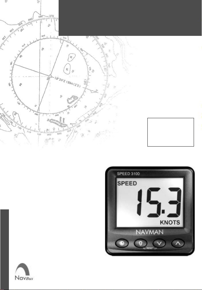
SPEED 3100 log
Installation and
Operation Manual
English .............2
Français .........16
Español ..........29
Português ......42
www.navman.com
NAVMAN
Page 2

FCC Statement
Note: This equipment has been tested and found to comply with the limits for a Class B
digital device, pursuant to Part 15 of the FCC Rules. These limits are designed to
provide reasonable protection against harmful interference in a normal installation. This
equipment generates, uses and can radiate radio frequency energy and, if not installed
and used in accordance with the instructions, may cause harmful interference to radio
communications. However, there is no guarantee that interference will not occur in a
particular installation. If this equipment does cause harmful interference to radio or
television reception, which can be determined by turning the equipment off and on, the
user is encouraged to try to correct the interference by one or more of the following
measures:
Reorient or relocate the receiving antenna
Increase the separation between the equipment and receiver
Connect the equipment into an output on a circuit different from that to which the
receiver is connected
Consult the dealer or an experienced technician for help
A shielded cable must be used when connecting a peripheral to the serial ports.
2
NAVMAN
SPEED 3100 log Installation and Operation Manual
Page 3

Contents
1 Introduction ..................................................................................................... 4
2 Operation ......................................................................................................... 5
2-1 Turn on and off ............................................................................................................5
2-2 Basic operation............................................................................................................ 5
2-3 Change units ............................................................................................................... 5
2-4 Simulate mode............................................................................................................. 5
2-5 Key reference .............................................................................................................. 6
3 Speed, average speed, maximum speed, trim speed .................................. 7
3-1 Set speed and log units ............................................................................................... 7
3-2 Reset average speed ...................................................................................................7
3-3 Reset maximum speed ................................................................................................ 7
3-4 Reset trim speed ......................................................................................................... 7
3-5 Set speed damping...................................................................................................... 7
3-6 Set speed resolution .................................................................................................... 7
3-7 Calibrate speed ........................................................................................................... 8
4 Log and total log ............................................................................................. 8
4-1 Reset log ..................................................................................................................... 8
4-2 Reset total log.............................................................................................................. 8
5 Temperature..................................................................................................... 9
5-1 Set temperature units .................................................................................................. 9
5-2 Calibrate temperature .................................................................................................. 9
6 Countdown timer ............................................................................................. 9
6-1 Start countdown timer .................................................................................................. 9
6-2 Stop and reset countdown timer................................................................................... 9
6-3 Adjust start time ...........................................................................................................9
7 Systems of several instruments .................................................................. 10
7-1 NavBus ..................................................................................................................... 10
7-2 NMEA ....................................................................................................................... 10
8 SPEED 3100 hardware ...................................................................................1 1
8-1 What comes with your SPEED 3100 ......................................................................... 1 1
8-2 Other parts required .................................................................................................. 11
8-3 Transducers .............................................................................................................. 11
8-4 Accessories............................................................................................................... 11
9 Installation and setup.................................................................................... 12
9-1 Installation ................................................................................................................. 12
9-2 Setup......................................................................................................................... 13
9-3 Resetting to factory defaults ...................................................................................... 14
Appendix A - S pecifications ............................................................................ 14
Appendix B - Troubleshooting ........................................................................ 15
Appendix C - How to contact us ..................................................................... 55
Units
The factory default units are °C, knots and nautical miles. To change these units, please refer to section 2-3 of
this manual.
NAVMAN
SPEED 3100 log Installation and Operation Manual
3
Page 4
1 Introduction
The SPEED 3100 measures and displays boat speed
and water temperature. It can calculate and display
average speed, maximum speed, trim speed, trip log
(distance) and total log.
An installed SPEED 3100 usually has two parts:
The display unit.
A speed / temperature transducer which is
attached to the hull and wired to the display unit.
The unit is powered from the boat’s power supply.
The SPEED 3100 is part of the NAVMAN family of
instruments for boats, which includes instruments
for speed, depth, wind and repeaters. These
instruments can be connected together to form an
integrated data system for a boat (see section 7).
For maximum benefit, please read this manual
carefully before installation and use.
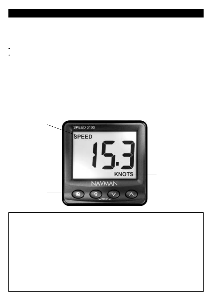
The SPEED 3100 display unit
Display
(backlit)
How the transducer measures speed
The speed transducer has a small paddlewheel
which spins as the boat moves through the water.
The transducer measures how fast the paddlewheel
is spinning and calculates the boat speed by
averaging several measurements.
Cleaning and maintenance
Clean the display unit and the plastic transducer with
a damp cloth or mild detergent. Avoid abrasive
cleaners, petrol or other solvents.
When repainting the hull, cover or remove any visible
transducer. Do not use a high pressure water blast
on the speed transducer paddlewheel as it may
damage the bearings.
Display showing
boat speed
Speed units
Four keys
(backlit)
111 x 111 mm
(4.4" x 4.4")
Important
It is the owner’s sole responsibility to install and use the instrument and transducer/s in a manner that will
not cause accidents, personal injury or property damage. The user of this product is solely responsible for
observing safe boating practices.
NAVMAN NZ LIMITED DISCLAIMS ALL LIABILITY FOR ANY USE OF THIS PRODUCT IN A W A Y THA T
MAY CAUSE ACCIDENTS, DAMAGE OR THA T MAY VIOLATE THE LAW .
This manual represents the SPEED 3100 as at the time of printing. Navman NZ Limited reserves the right
to make changes to specifications without notice.
Governing Language: This statement, any instruction manuals, user guides and other information relating
to the product (Documentation) may be translated to, or has been translated from, another language
(Translation). In the event of any conflict between any Translation of the Documentation, the English
language version of the Documentation will be the official version of the Documentation.
Copyright © 2002 Navman NZ Limited, New Zealand. All rights reserved. NA VMAN is a registered trademark
of Navman NZ Limited.
4
NAVMAN
SPEED 3100 log Installation and Operation Manual
Page 5
2 Operation
2-1 T urn on and off
Turn the unit on and off with the auxiliary power switch
on the boat. The unit does not have its own power
switch. When you turn it off, any settings you have
made are retained.
If the word SIMULATE flashes at the top, left of the display ,
then the unit is in simulate mode (see section 2-4).
2-2 Basic operation
The keys
The unit has four keys, labelled and .
In this manual:
Press means to push the key for less than one
second
Hold for two seconds means to hold the key
down for two seconds or more
Press one key + another key means to push
both keys together.
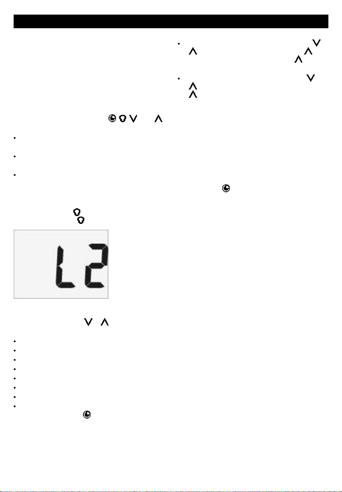
Set backlight for screen and keys
You can set the backlight to one of four brightness
levels or off. Press
backlight level, press
Change the item displayed
The display shows one item at a time. To change
what is displayed, press
The choices are:
Speed.
Avg speed.
Max speed.
Trim speed.
Temperature.
Trip log (distance).
Total log (distance).
Battery voltage.
To use the timer, press
once to display the current
again to change the level:
Backlight
level 2
or one or more times.
(see section 6).
2-3 Change units
To change the speed and log units, press or
until SPEED is displayed, then hold until
the units change; if necessary, hold again
until the units change again.
To change the temperature units, press or
until the temperature is displayed, then hold
until the units change.
2-4 Simulate mode
Simulate mode allows you to become familiar with
the unit off the water. In Simulate mode, the SPEED
3100 functions normally except that the transducer
is ignored and the unit generates this data internally.
The word SIMULATE flashes at the top, left corner
of the screen.
To turn Simulate mode on or off:
1 Turn the power off.
2 Hold down
while you turn the power on.
NAVMAN
SPEED 3100 log Installation and Operation Manual
5
Page 6
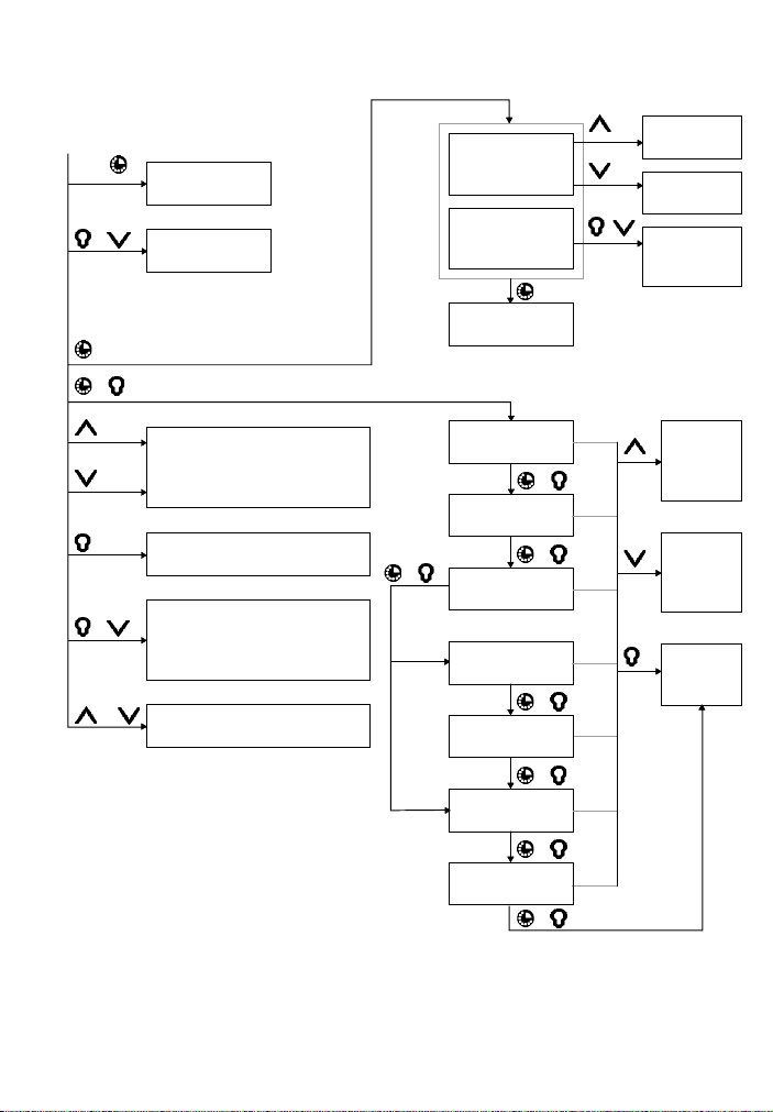
2-5 Key reference
Countdown timer
Turn power on
Hold
Hold
+
5 sec
Normal operation
+
+
Hold
or
2 sec
Turn Simulate
on or off
Reset memory
Change display (Speed, Avg
speed, Max speed, Trim speed,
Temperature, Log, Total log,
Battery voltage)
Adjust backlight
(4 levels or off)
Reset value to zero
(Avg speed, Max speed, Trim
speed, Log, Total log (hold for
5 sec) )
Change units
(e.g. knots, °C)
+
Mode
is SEn
Mode
is GPS
When countdown
timer is stopped
When countdown
timer is running
Return to normal
operation
Setup
Set Speed
Damping
+
Set T emperature
Calibration
+
Set Speed Mode
Sen(sor) or GPS
Set Speed Calibration by Speed
+
Set Speed Calibration by Log
+
Set Speed
Display
+
Set Backlight
Group
+
+
Change start
time
Start countdown timer
Stop & reset
countdown
timer
Increase
value or
change
setting
Decrease
value or
change
setting
Return to
normal
operation
6
NAVMAN
SPEED 3100 log Installation and Operation Manual
Page 7

3 Speed, average speed, maximum speed, trim speed
The unit can display several speeds:
SPEED: The current boat speed.
AVG SPEED: The average speed since AVG
SPEED was reset or the unit was switched on.
MAX SPEED: The maximum speed since MAX
SPEED was reset or the unit was switched on.
TRIM SPEED: Trim speed may be used for
tuning racing boats. Trim speed measures
changes in boat speed, relative to when you
reset trim speed to zero. For example, if the
boat is travelling at 10 knots and you reset trim
speed, then trim speed is zero. Then:
If the boat speed increases to 11.5 knots,
the trim speed is 1.5 knots.
If the boat speed decreases to 8.5 knots,
the trim speed is -1.5 knots.
3-1 Set speed and log units
The speed units can be selected to be KNOTS, KPH
and MPH. Selecting one of these automatically sets
the log distance units to NM, KM or M (miles):
Press or until SPEED is displayed, then
hold until the units change; if necessary,
hold again until the units change again.
3-2 Reset average speed
Resetting starts calculating a new average speed:
1 Press
2 Press
or until AVG SPEED is displayed.
+ .
3-3 Reset maximum speed
Resetting starts calculating a new maximum:
1 Press
2 Press
or until MAX SPEED is displayed.
+ .
3-4 Reset trim speed
Resetting sets the trim speed to zero:
1 Press
2 Press
until TRIM SPEED is displayed.
+ .
3-5 Set speed damping
Waves and wind cause the boat speed to fluctuate
slightly. To give a stable reading, the SPEED 3100
calculates the boat speed and trim speed by
measuring the speed several times and averaging
the measurements. The speed damping value
ranges from 1 to 5:
A lower value averages readings over a shorter
period of time. This gives the most accurate
speed but has the most fluctuations.
A higher value averages readings over a longer
period of time. This gives the most stable speed
but will ignore some true speed changes.
Set the speed damping to the lowest value which
gives a stable speed reading. Values of 1, 2, 3, 4
and 5 average readings over a time period of 6, 12,
18, 24 and 30 seconds respectively. To get the most
accurate, stable trim speeds, you may need to
increase the damping. To set speed damping:
1 Press
2 Press
3 Press
+ several times until the Speed
Damping screen is displayed:
or to change the damping.
.
3-6 Set speed resolution
This sets how speeds are displayed. It has two
settings:
0.0 Displays speeds as 0.0 to 19.9, 20 up.
0.00 Displays speeds as 0.00 to 19.99, 20.0 to
29.9, 30 up:
To set the speed resolution:
1 Press
2 Press
3 Press
+ several times until the Speed
Resolution screen is displayed:
or to change the resolution
setting.
.
Damping
equals 4
Value
equals
0.0 or 0.00
NAVMAN
SPEED 3100 log Installation and Operation Manual
7
Page 8

3-7 Calibrate speed
Calibration may be required, because different hull
shapes have different water flow characteristics.
Speed calibration can be done either by the speed
or by the log, as described below. If speed readings
are taken from a GPS receiver (see section 7), then
you can not calibrate it.
Calibrate by speed
In this method, travel at a measured, constant speed.
Use the speed displayed on a GPS receiver, follow
another boat travelling at a known speed or make a
timed run over a known distance.
Note that for accurate calibration:
The speed from a GPS receiver should be
above 5 knots.
The speed from another paddlewheel
transducer should be between 5 and 20 knots.
Best results are achieved in calm conditions
where there is minimal current (best at high or
low tide).
Continue travelling at this measured, constant speed
and calibrate the speed as follows:
Measured
speed
1 Press + several times until the Speed
Calibration screen is displayed (after this, it
does not matter if the boat speed changes).
2 Press
3 Press
Calibrate by log
In this method, travel a known distance in a straight
line over a course. Best results are achieved in calm
conditions where there is minimal current (best at
high or low tide). Tidal effects may be reduced by
making the trip twice, parallel to the current, once in
each direction:
1 At the start of the course, reset the trip log (see
2 At the end, note the trip log distance (see
3 Press
4 Press
5 Press
or to change the displayed speed
to the measured boat speed.
.
Distance
travelled
section 4-1). Travel in a straight line over the
course, then repeat in the other direction.
section 4).
+ several times until the Speed
Calibration by Log screen is displayed.
or to change the displayed
distance travelled to the actual distance you
travelled over the course.
.
4 Log and total log
The SPEED 3100 has two distance logs:
LOG: Trip distance. The distance travelled
since log was reset.
TOTAL LOG: Total distance. The distance
travelled since total log was reset:
Total log
8
The log units are NM, KM or M (miles) and
correspond to the speed units, for example if you set
the speed units to KPH then the log units are KM
(see section 3-1).
4-1 Reset log
Resetting zeros the log (trip distance):
1 Press
2 Press
or until LOG is displayed.
+ .
4-2 Reset total log
Resetting zeros the total log (total distance), as well
as the log:
1 Press
2 Hold
or until TOTAL LOG is displayed.
+ for five seconds.
NAVMAN
SPEED 3100 log Installation and Operation Manual
Page 9

5 Temperature
T emperature is measured by a sensor in the speed
transducer.
5-1 Set temperature units
The units can be °C or °F:
Press or until the temperature is
displayed, then hold until the units change.
5-2 Calibrate temperature
The unit is factory calibrated and should not normally
need calibrating. To calibrate:
1 Measure the water temperature near the speed
transducer.
6 Countdown timer
To go to timer mode, press . To return to normal
mode, press again.
Y ou can adjust the countdown timer to between one
and ten minutes, in increments of one minute. The
factory default start time is 10 minutes. When the
timer is counting down, TIMER flashes at the top of
the screen and in timer mode the time to go is
displayed in minutes and seconds:
Flashes
Timer
counting
down
The beeper sounds and any external beepers or
lights operate:
Four beeps at four minutes to go.
Three beeps at three minutes.
Two beeps at two minutes.
One beep at one minute.
Ten beeps at the end; the last beep is longer
and marks the end of the countdown.
In each case, the end of the last beep marks the
exact minute.
2 Press
3 Press
4 Press
+ several times until the
Temperature Calibration screen is displayed:
Water
temperature
or to change the temperature to
the value measured in step 1 above.
.
6-1 Start countdown timer
1 If you are not in timer mode, press to go to
timer mode (to adjust the start time, see
section 6-3).
2 Press
. The timer displays On briefly and
starts counting down from the start time.
6-2 Stop and reset countdown timer
1 If you are not in timer mode, press to go to
timer mode.
2 Press
+ . The timer stops and the time
resets to the start time (see section 6-3).
6-3 Adjust start time
1 If you are not in timer mode, press to go to
timer mode.
2 If the timer is counting down, press
stop the timer.
3 Press
one or more times to set the start
time in minutes. The timer does not start now
(to start the timer, see section 6-1).
+ to
Timer set to
9 min
NAVMAN
SPEED 3100 log Installation and Operation Manual
9
Page 10

7 Systems of several instruments
Several NAVMAN instruments can be connected
together to share data. There are two ways of
connecting instruments together, NavBus or NMEA.
7-1 NavBus
NavBus is a NAVMAN proprietary system that allows
systems of multiple instruments to be built using a
single set of transducers. When instruments are
connected by NavBus:
If you change the units, alarms or calibration in
one instrument, then the values will
automatically change in all other instruments
of the same type.
Each instrument can be assigned to a group of
instruments (see section 9-2, step 3). If you
change the backlight in an instrument in group
1, 2, 3 or 4 then the backlight will automatically
change in the other instruments in the same
group. If you change the backlight in an
instrument in group 0 then no other
instruments are affected.
If an alarm sounds, mute it by pressing on
any instrument which can display that alarm.
NavBus and the SPEED 3100
If the SPEED 3100 does not have a speed/
temperature transducer fitted then the unit will
automatically take speed and temperature
readings from another instrument, via NavBus, if
the data is available. For more information, refer
to the NavBus Installation and Operation Manual.
If the boat has a GPS instrument connected to
the instruments via NavBus then you can set up
the SPEED 3100 to use this for speed readings
instead of a speed transducer (see section 9-1
for wiring and section 9-2, step 2 for setup).
Note: The speed from a paddlewheel sensor
is the speed that the boat is moving through
the water. A speed from a GPS is the speed
over the ground. If there is a current then
these two speeds will be different.
If a transducer is not fitted to the unit and the
corresponding external data is not available then
the displayed value will be 0 (for example, when
using a GPS input for speed and no speed/
temperature transducer is fitted to any instrument
on the NavBus then temperature displays as 0).
7-2 NMEA
NMEA is an industry standard, but is not as flexible
as NavBus as it requires dedicated connections
between instruments. Speed, temperature and log
data are output by the SPEED 3100 and can be read
and displayed by the NAVMAN REPEAT 3100 or
other NMEA instrument. The SPEED 3100 can also
receive GPS speed data (NMEA RMC) from any
compatible NMEA GPS instrument - GPS speed
must be selected (see section 9-2, step 2).
10
NAVMAN
SPEED 3100 log Installation and Operation Manual
Page 11

8 SPEED 3100 hardware
8-1 What comes with your SPEED 3100
The SPEED 3100 comes in several configurations.
Standalone configuration
SPEED 3100 unit with protective cover.
Warranty card.
Mounting template.
This Installation and Operation manual.
In addition, the standalone configuration usually
requires a speed/temperature transducer (see
section 8-3).
Kit configuration
The SPEED 3100 is available in several kit
configurations with different grades of through hull
transducer, with:
The parts for the standalone configuration,
listed above.
Through hull speed/temperature transducer
Transducer Installation manual.
8-2 Other parts required
One or more 3100 series instruments will be
connected to the boat 12 V power supply via:
An accessory switch to turn the instruments on
and off.
A fuse: Use a 1 A fuse for between one and five
instruments.
Optional external beepers or lights can be fitted. The
SPEED 3100 output is switched to ground, 30 V DC
and 250 mA maximum. If the beepers and lights
require more than 250 mA, fit a relay.
For systems of several instruments, wiring and
connectors are required (see section 7 or the NavBus
Installation and Operation manual).
8-3 Transducers
The SPEED 3100 is usually used with a through hull
speed/temperature transducer. However , the unit can
take readings from another instrument, in which case
it may not need a transducer (see section 7).
A through hull transducer generally gives the best
performance and is the best choice for displacement
hulls. It is mounted in a hole drilled through the bottom
of the boat.
A plastic through hull transducer is suitable for
GRP or metal hulls. Plastic through hull
transducers are not suitable for solid wood
hulls. (Use NAVMAN’ s bronze transducers).
A bronze transducer is suitable for wood or
fibreglass hulls. Never install a bronze
transducer in a metal hull, because it will
cause electrolytic corrosion.
A range of NAVMAN through hull transducers are
available, for more information, refer to the
Transducer Installation manual or consult your
NAVMAN dealer .
8-4 Accessories
These accessories are available from your NAVMAN dealer.
NavBus junction box
(See section 7-1)
NAVMAN
SPEED 3100 log Installation and Operation Manual
4 m (13 ft) speed
transducer extension
cable
Through hull speed
transducer skin fitting
Through hull speed
paddlewheel
11
Page 12

9 Installation and setup
Correct installation is critical to the performance of
the unit. It is vital to read this section of the manual
and the documentation that comes with the other
parts before starting installation.
The SPEED 3100 can:
Drive external beepers or lights for the
countdown timer.
Send and receive data from other NAVMAN
instruments connected via NavBus. Settings
for alarms, units, calibration and backlighting
are shared (see section 7-1).
Send and receive NMEA data from other
instruments (see section 7-2).
Warnings
The unit is waterproof from the front. Protect the rear
of the unit from water, or else water might enter the
breathing hole and damage the unit. The warranty
does not cover damage caused by moisture or water
entering the back of the unit.
Ensure that any holes that you cut will not weaken
the boat’s structure. If in doubt, consult a qualified
boat builder.
The choice, location, angle and installation of
the transducers is the most critical part of the
installation. If they are not correct, the unit can
not perform at its designed potential. If in
doubt, consult your NAVMAN dealer. Plastic
through hull transducers are usually unsuitable
for wood hulls. If in doubt, consult a marine
surveyor or marine engineer.
9-1 Installation
SPEED 3100 display unit
1 Choose a location for the display unit that is:
Easily seen and protected from damage.
At least 100 mm (4") from a compass and
at least 500 mm (1.65 ft) from a radio or
radar antenna.
Away from engines, fluorescent lights, and
power inverters.
Accessable from behind; the minimum
clearance required at the back is 50 mm
(2") (see mounting diagram).
With the back of the unit protected from
moisture.
2 The unit must mount on a flat panel which is
less than 20 mm (0.75") thick. Stick the
mounting template in place. Drill a 50 mm (2")
fixing hole through the centre hole in the
template. Note that the template allows space
around the unit for the protective cover.
3 Remove the fixing nut from the back of the unit.
Insert the stud at the back of the unit through
the mounting hole. Hand tighten the fixing nut.
Transducer
1 If the SPEED 3100 does not come with a
transducer, choose a suitable transducer (see
section 8-3). If the SPEED 3100 is supplied
with a transducer, see section 8-3 to ensure
that it is suitable.
2 Choose a suitable location for the transducer
and install it by following the instructions in the
Transducer Installation manual.
3 Fit the cables between the transducer and the
display unit:
Keep the cable away from other cables,
engines, fluorescent lights, power inverters
and radio or radar transmitters.
Ensure no connectors lay in the bilge.
If necessary, extend the cable by adding
extension cables
Secure the cable at regular intervals.
4 Connect the transducer to the display unit
connector.
Side view of display unit mounting
20 mm (0.75")
maximum thickness
Fixing hole
50 mm (2")
Display unit
Clearance 50 mm (2") minimum
Fixing nut
Cables
12
NAVMAN
SPEED 3100 log Installation and Operation Manual
Page 13

Power/data wiring
1 Wire the display unit power/data cable:
The unit requires 12 V DC power. Fit a
power switch and fuse to the power supply
or power the unit from a fused auxiliary
switch. The fuse should be 1 A for up to five
instruments.
If the external beepers and lights require
more than 250 mA DC total, fit a relay.
A single unit can be wired as shown below:
9-2 Set up
1 Take the boat for a trial run to check that all the
instruments work correctly.
2 If the unit will take speed readings from a GPS
receiver (rather than a speed transducer or an
external speed input from an instrument with a
speed transducer - see section 7):
i Press
+ several times until the Speed
Mode screen is displayed:
Masthead
unit cable
Black
Red
Green
Yellow
NMEA in (GPS, optional)
White
NMEA out (optional)
Orange
}
NavBus (optional)
Blue
Switch
External beepers or
lights (optional)
Fuse
12 V DC
power
With several instruments, use the optional
junction boxes to simplify wiring, as shown
below:
Group 1
Junction box
Power
& data
connections
Power/data cables
Group 2
NavBus cable
Junction box
Power/data cable
Power & data
connections
For information on how to connect NavBus and
to use junction boxes, refer to the NavBus
Installation and Operation Manual.
2 Tape or cover any unused wires or connectors
to protect them from water and keep them from
shorting together.
ii Press
or to change the mode to GPS
(when using a speed transducer, the mode
should be SEn).
iii Press
.
3 If the unit is part of a system of 3100 series
instruments connected by NavBus, set the
backlight group number (see section 7-1):
i Press
+ several times until the
Backlight Group screen is displayed:
Group 3
ii Press
or to set the backlight group
number.
iii Press
.
4 Set:
Speed and log units (see section 3-1).
The speed resolution (see section 3-6).
The temperature units (see section 5-1).
5 Calibrate if required:
Speed (see section 3-7).
Temperature (see section 5-2).
NAVMAN
SPEED 3100 log Installation and Operation Manual
13
Page 14

9-3 Resetting to factory defaults
All settings may be reset to the manufacturer’s default
settings (see right).
T o reset to factory defaults:
1 Turn the power off.
2 Hold down + while you turn the power on
and continue to hold the keys down for at least
5 seconds.
Appendix A - Specifications
Physical
Case size 111 mm (4.4") square.
LCD display 82 mm (3.2") wide, 61 mm (2.4")
high; twisted nematic.
LCD digits 38 mm (1.4") high.
Four operator keys, laser etched.
Backlighting for display and keys, amber, four
levels and off.
Operating temperature 0 to 50°C (32 to 122°F)
Transducer cable length 8 or 9 metres (26.25 ft
or 29.5 ft), depending on transducer.
Power Cable length 1m (3.25 ft).
Electrical
Power supply 10.5 to 16.5 V DC, 30 mA without
backlighting, 100 mA with full backlighting and
transducer.
External beeper or light output, switched to
ground, 30 V DC and 250 mA maximum.
Speed
Displays current speed, average speed,
maximum speed, trim speed.
Range 0 to 50 knots (0 to 58 mph, 0 to 93 km/h).
Display resolution either 0.0 to 19.9, 20 up or
0.00 to 19.99, 20.0 to 29.9, 30 up.
Trim speed displays ± .00 to .99, 1.0 to 9.9,
10 up.
Adjustable damping for speed and trim speed;
values of 1, 2, 3, 4 & 5 average readings over a
time period of 6, 12, 18, 24 & 30 seconds
respectively.
Log
Displays trip log and total log.
Range 0 to 1999 km, miles or nautical miles.
Displays 0.00 to 19.99, 20.0 to 199.9, 200 up.
Speed units............................................ Knots
Temperature units ....................................... °C
Speed resolution ........................................ 0.0
Speed damping ............................................. 2
Countdown timer start time.................10 min
Distance logs................................................. 0
SIMULATE mode ........................................ Off
Backlight level ...............................................0
Backlight group ............................................. 1
Temperature
Range 0 to 37.7°C (32 to 99.9°F); typical
accuracy < 2°C (32.5°F).
Resolution 0.1 degree.
Countdown timer
Can be set to between 1 and 10 minutes, in
increments of 1 minute.
Counts down in minutes and seconds.
Calibration
Speed and temperature can be calibrated.
Interfaces
NavBus connection to other NAVMAN
instruments.
NMEA 0183 outputs: MTW, PTTKV, VHW,
VLW; input RMC.
Standards compliance
EMC compliance
USA (FCC): Part 15 Class B.
Europe (CE): EN50081-1, EN50082-1
New Zealand and Australia (C Tick):
AS-NZS 3548.
Environment: IP66 from front when correctly
mounted.
Power/data cable wires
Wire Signal
Red Power positive, 12 V DC, 100 mA
maximum
Black Power negative, NMEA common
Green External beeper or light out, switched to
ground, 30 V DC and 250 mA max.
Orange NavBus +
Blue NavBus White NMEA out
Y ellow NMEA in
14
NAVMAN
SPEED 3100 log Installation and Operation Manual
Page 15

Appendix B - Troubleshooting
This troubleshooting guide assumes that you have
read and understood this manual.
It is possible in many cases to solve difficulties
without having to send the unit back to the
manufacturer for repair. Please follow this
troubleshooting section before contacting the
nearest NAVMAN dealer .
There are no user serviceable parts. Specialized
methods and testing equipment are required to
ensure that the unit is reassembled correctly and is
waterproof. Repairs to the unit must only be carried
out by a service centre approved by Navman NZ
Limited. Users who service the unit themselves will
void the warranty.
More information can be found on our Website:
www.navman.com.
1 Unit will not turn on:
a Fuse blown or circuit breaker tripped.
b Battery voltage is outside the range 10.5 to
16.5 V DC.
c Power/data cable damaged.
2 Speed reading wrong or erratic:
a Calibration is incorrect (see section 3-7).
b Speed transducer cable unplugged or
damaged.
c Speed/temperature transducer fouled or
damaged. Check paddlewheel is aligned
fore and aft in the fitting. Remove
paddlewheel from fitting, check for fouling
or damage. Spin paddlewheel by hand,
check for a speed reading.
d Speed transducer installed incorrectly or
transducer does not have a smooth flow of
clear water over it. Review installation.
e Interference from electrical noise. Review
installation.
3 Temperature reading wrong:
a Calibration is incorrect (see section 5-2).
b Speed/temperature transducer cable
damaged.
4 The word SIMULATE flashes at top, left of
screen, values displayed are unexpected:
a Unit is in simulate mode (see section 2-4).
5 The display fogs:
a Moist air has entered the breathing tube at
the rear of the unit. Air the boat or run unit
with backlight fully on.
b Water has entered the breathing tube.
Return unit for service.
NAVMAN
SPEED 3100 log Installation and Operation Manual
15
Page 16

Appendix C - How to contact us www.navman.com.
NORTH AMERICA
NAVMAN USA INC.
18 Pine St. Ext.
Nashua, NH 03060.
Ph: +1 603 577 9600
Fax: +1 603 577 4577
e-mail: sales@navmanusa.com
OCEANIA
New Zealand
Absolute Marine Ltd.
Unit B, 138 Harris Road,
East Tamaki, Auckland.
Ph: +64 9 273 9273
Fax: +64 9 273 9099
e-mail:
navman@absolutemarine.co.nz
Australia
NAVMAN AUSTRALIA PTY
Limited
Unit 6 / 5-13 Parsons St,
Rozelle, NSW 2039, Australia.
Ph: +61 2 9818 8382
Fax: +61 2 9818 8386
e-mail: sales@navman.com.au
SOUTH AMERICA
Argentina
HERBY Marina S.A.
Costanera UNO,
Av Pte Castillo Calle 13
1425 Buenos Aires, Argentina.
Ph: +54 11 4312 4545
Fax: +54 11 4312 5258
e-mail:
herbymarina@ciudad.com.ar
Brazil
REALMARINE
Estrada do Joa 3862,
CEP2611-020,
Barra da Tijuca, Rio de Janeiro,
Brasil.
Ph: +55 21 2483 9700
Fax: +55 21 2495 6823
e-mail:
vendas@marinedepot.com.br
Equinautic Com Imp Exp de
Equip Nauticos Ltda.
Av. Diario de Noticias 1997 CEP
90810-080, Bairro Cristal, Porto
Alegre - RS, Brasil.
Ph: +55 51 3242 9972
Fax: +55 51 3241 1134
e-mail:
equinautic@equinautic.com.br
NAVMAN
SPEED 3100 log Installation and Operation Manual
ASIA
China
Peaceful Marine Electronics Co. Ltd.
Hong Kong, Guangzhou,
Shanghai, Qindao, Dalian.
E210, Huang Hua Gang Ke Mao
Street, 81 Xian Lie Zhong Road,
510070 Guangzhou, China.
Ph: +86 20 3869 8784
Fax: +86 20 3869 8780
e-mail:
sales@peaceful-marine.com
Website:
www.peaceful-marine.com
Korea
Kumho Marine Technology Co. Ltd.
# 604-816, 3F, 1117-34,
Koejung4-Dong, Saha-ku
Pusan, Korea
Ph: +82 51 293 8589
Fax: +82 51 294 0341
e-mail: info@kumhomarine.com
Website:
www.kumhomarine.com
Malaysia
Advanced Equipment Co.
43A, Jalan Jejaka 2, Taman
Maluri, Cheras 55100, Kuala Lumpur.
Ph: +60 3 9285 8062
Fax: +60 3 9285 0162
e-mail: ocs@pc.jaring.my
Singapore
RIQ PTE Ltd.
Blk 3007, Ubi Road 1,
#02-440, Singapore 408701
Ph: +65 6741 3723
Fax: +65 6741 3746
HP: +65 9679 5903
e-mail: riq@postone.com
Thailand
Thong Electronics (Thailand)
Company Ltd.
923/588 Thaprong Road,
Mahachai,
Muang, Samutsakhon 74000,
Thailand.
Ph: +66 34 411 919
Fax: +66 34 422 919
e-mail: thonge@cscoms.com
Vietnam
Haidang Co. Ltd.
16A/A1E, Ba thang hai St.
District 10, Hochiminh City.
Ph: +84 8 86321 59
Fax: +84 8 86321 59
e-mail:
sales@haidangvn.com
Website: www.haidangvn.com
MIDDLE EAST
Lebanon and Syria
Letro, Balco Stores,
Moutran Street, Tripoli
VIA Beirut.
Ph: +961 6 624512
Fax: +961 6 628211
e-mail: balco@cyberia.net.lb
United Arab Emirates
Kuwait, Oman & Saudi Arabia
AMIT, opp Creak Rd.
Baniyas Road, Dubai.
Ph: +971 4 229 1195
Fax: +971 4 229 1198
e-mail: mksq99@email.com
AFRICA
South Africa
Pertec (Pty) Ltd Coastal,
Division No.16 Paarden Eiland Rd.
Paarden Eiland, 7405
Postal Address: PO Box 527,
Paarden Eiland 7420
Cape Town, South Africa.
Ph: +27 21 511 5055
Fax: +27 21 511 5022
e-mail: info@kfa.co.za
EUROPE
France, Belgium and
Switzerland
PLASTIMO INTERNATIONAL
15, rue Ingénieur Verrière,
BP435,
56325 Lorient Cedex.
Ph: +33 2 97 87 36 36
Fax: +33 2 97 87 36 49
e-mail: plastimo@plastimo.fr
Website: www.plastimo.fr
Germany
PLASTIMO DEUTSCHLAND
15, rue Ingénieur Verrière
BP435
56325 Lorient Cedex.
Ph: +49 6105 92 10 09
+49 6105 92 10 10
+49 6105 92 10 12
Fax: +49 6105 92 10 11
e-mail:
plastimo.international@plastimo.fr
Website: www.plastimo.de
Italy
PLASTIMO ITALIA
Nuova Rade spa, Via del Pontasso 5
I-16015 CASELLA SCRIVIA (GE).
Ph: +39 1096 8011
Fax: +39 1096 8015
e-mail: info@nuovarade.com
Website: www.plastimo.it
Holland
PLASTIMO HOLLAND BV.
Industrieweg 4,
2871 JE SCHOONHOVEN.
Ph: +31 182 320 522
Fax: +31 182 320 519
e-mail: info@plastimo.nl
Website: www.plastimo.nl
United Kingdom
PLASTIMO Mfg. UK Ltd.
School Lane - Chandlers Ford
Industrial Estate,
EASTLEIGH - HANTS S053 ADG.
Ph: +44 23 8026 3311
Fax: +44 23 8026 6328
e-mail: sales@plastimo.co.uk
Website: www.plastimo.co.uk
Sweden, Denmark or Finland
PLASTIMO NORDIC AB.
Box 28 - Lundenvägen 2,
47321 HENAN.
Ph: +46 304 360 60
Fax: +46 304 307 43
e-mail: info@plastimo.se
Website: www.plastimo.se
Spain
PLASTIMO ESPAÑA, S.A.
Avenida Narcís Monturiol, 17
08339 VILASSAR DE DALT,
(Barcelona).
Ph: +34 93 750 75 04
Fax: +34 93 750 75 34
e-mail: plastimo@plastimo.es
Website: www.plastimo.es
Other countries in Europe
PLASTIMO INTERNATIONAL
15, rue Ingénieur Verrière
BP435
56325 Lorient Cedex, France.
Ph: +33 2 97 87 36 59
Fax: +33 2 97 87 36 29
e-mail:
plastimo.international@plastimo.fr
Website: www.plastimo.com
REST OF WORLD /
MANUFACTURERS
NAVMAN NZ Limited
13-17 Kawana St. Northcote.
P.O. Box 68 155 Newton,
Auckland, New Zealand.
Ph: +64 9 481 0500
Fax: +64 9 480 3176
e-mail:
marine.sales@navman.com
Website:
www.navman.com
55
Page 17

Made in New Zealand
MN000133 1951319B
SPEED 3100
Lon 174° 44.535’E
Lat 36° 48.404’S
NAVMAN
 Loading...