

Page 1
1
Lone Worker
Solution
Installation Manual
Page 2

Lone Worker Solution | Installation Manual
2
Contents
Disclaimer ....................................................................................................... 3
1 Introduction ............................................................................................... 5
1.1 Product Overview........................................................................................ 5
1.2 Audience .................................................................................................... 5
1.3 Box Contents .............................................................................................. 6
2 Installation ................................................................................................. 7
2.1 Prerequisites .............................................................................................. 7
2.2 Installation Overview ................................................................................... 7
2.3 Find the Qube ............................................................................................ 8
2.4 Mount the Antenna ..................................................................................... 8
2.5 Mount the Charging Dock ............................................................................ 9
2.6 Mount the Interface Module ......................................................................... 9
2.7 Connect the Antenna to the Interface Module .............................................. 10
2.8 Connect the Charging Dock to the Interface Module ..................................... 10
3 Wiring ...................................................................................................... 11
3.1 Before Starting ......................................................................................... 11
3.2 Connect the Interface Module to the Qube .................................................. 11
3.3 Connect the Interface Module to the Ignition Loom or Fuse Box .................... 13
4 Commission Testing .................................................................................. 14
4.1 Configuration and Activation of Lone Worker Solution .................................. 14
4.2 Charge the Pendant .................................................................................. 14
4.3 Check the Ignition Connection ................................................................... 14
4.4 Test the Pendant High Priority Alert Function............................................... 14
4.5 Test the Person Down Alert Function .......................................................... 15
4.6 Test the Pendant Check In Function ........................................................... 15
4.7 Test the Antenna Alert Function ................................................................. 15
4.8 Test the Out of Range Warning .................................................................. 16
4.9 Handover ................................................................................................. 16
4.10 Troubleshooting ........................................................................................ 16
5 Configuring the System ............................................................................. 17
5.1 To Configure the Lone Worker System ........................................................ 17
5.2 Configuration Settings ............................................................................... 17
6 Contacts ................................................................................................... 18
Page 3

Lone Worker Solution | Installation Manual
3
Disclaimer
For the purpose of this notice, “you” and “your” means the party (including that party’s
personnel and any other person authorised by that party to use and/or install the Product)
that has either purchased or leased the Product from, or is using the Product as part of a
solution provided by, Navman Wireless or its related companies.
It is your sole responsibility to install the Lone Worker Solution (the Product) in accordance
with this installation Manual. The choice, location and installation of all components of the
Product is critical. If installation is not correct, the Product may not perform at its designed
potential or specifications.
TO THE MAXIMUM EXTENT PERMITTED BY LAW, ALL REPRESENTATIONS AND
WARRANTIES IN RESPECT OF THE PRODUCT AND ITS USE ARE EXPRESSLY EXCLUDED,
INCLUDING WITHOUT LIMITATION WARRANTIES AS TO MERCHANTABILITY AND
FITNESS FOR A PARTICULAR PURPOSE.
NAVMAN WIRELESS SHALL HAVE NO LIABILITY TO YOU OR YOUR PERSONNEL IN
CONNECTION WITH THE PRODUCT (INCLUDING YOUR OR YOUR PERSONNEL’S USE OF
THE PRODUCT) EXCEPT TO THE EXTENT THAT LIABILITY ARISES DIRECTLY FROM A
BREACH OF NAVMAN WIRELESS’ (OR ITS RELATED PARTIES’) WRITTEN OBLIGATIONS
TO YOU, OR FROM NAVMAN WIRELESS’ (OR ITS RELATED PARTIES’) NEGLIGENCE.
As Navman Wireless is continuously improving this Product, Navman Wireless may make
changes to the Product at any time which may not be reflected in this document. Please
contact your nearest Navman Wireless office if you require any further assistance.
EMC Compliance
This device complies with Part 15 of the FCC Rules.
Page 4

Lone Worker Solution | Installation Manual
4
Safety Warning - Lone Worker Pendant - Lithium Polymer Battery
Your Lone Worker Pendant contains a Lithium Polymer (LiPo) rechargeable battery that
provides excellent battery life and reliable use. They are widely used in many electronic
products today however Lithium Polymer batteries are known to be volatile, causing
explosion and fire if misused or mistreated and extra care and precautions should be taken
with any product that incorporates this type of battery.
Do not expose your Pendant to extreme temperatures. If the ambient temperature
external to the vehicle is higher than 45 Deg C, this will result in extremely high
temperatures inside the vehicle potentially creating an unsafe environment for your
Pendant . In these circumstances, please remove your Pendant from the vehicle.
If your Pendant is accidently immersed in water or other liquid, please discontinue use
immediately and contact your Navman Wireless service agent.
Do not attempt to connect your Pendant to any charger other than that provided with
the Lone Worker solution.
Do not attempt to open the Pendant or change or repair the battery for any reason.
If the Pendant stops charging properly or battery life becomes very low (< 1 day),
please stop using the Pendant immediately, do not attempt to charge any further and
return it to your Navman Wireless service agent.
Page 5
Lone Worker Solution | Installation Manual
5
1 Introduction
1.1 Product Overview
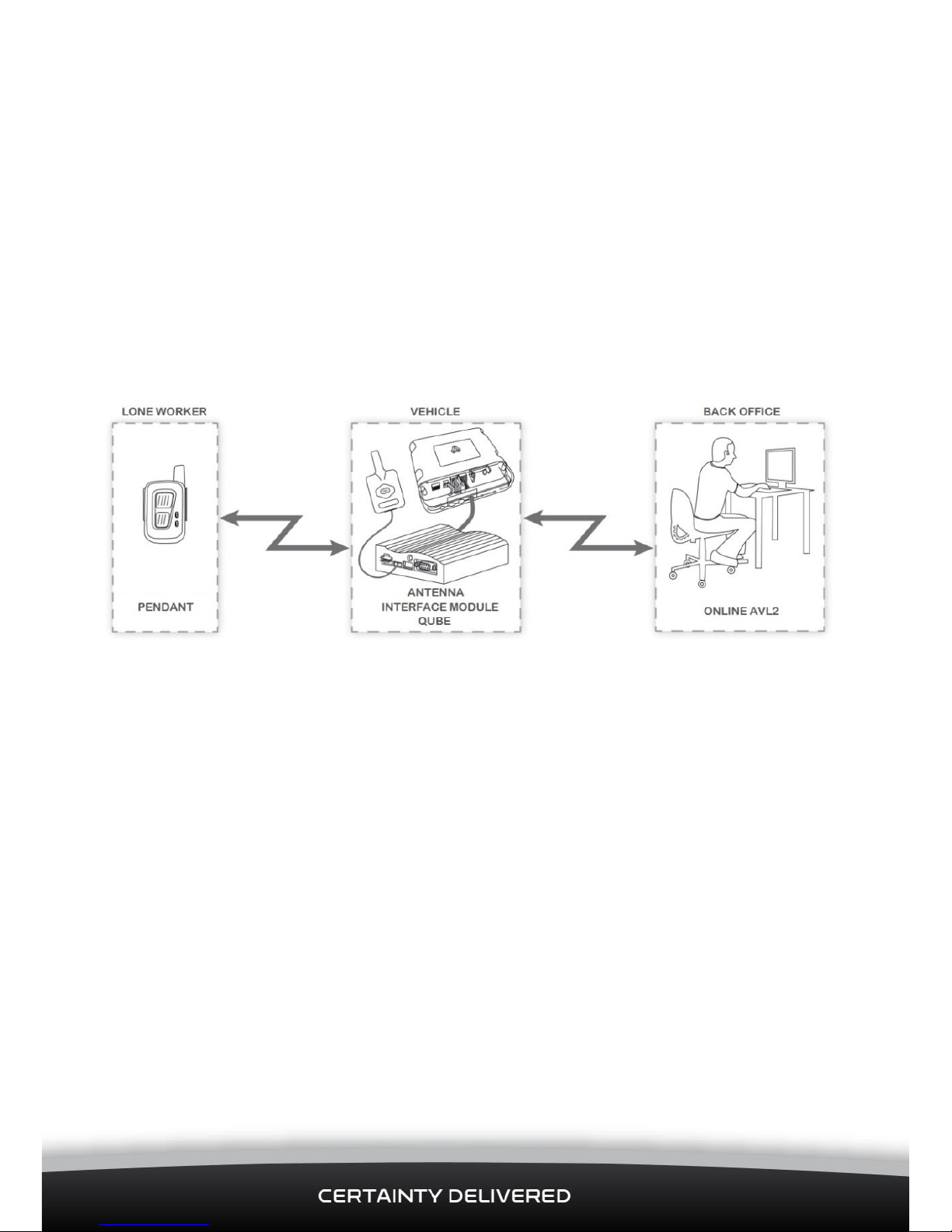
The Lone Worker Solution helps to create a safer working environment for anyone who is
working alone, away from their back office.
The lone worker wears a Pendant which communicates with an Antenna in the lone
worker’s vehicle. (The Antenna is usually mounted on the top of the glass windscreen
within easy reach of the driver).
The Antenna is linked to an Interface Module which is connected to the vehicle’s Qube.
This provides two-way communications with the lone worker’s back office through cellular
or satellite networks.
The lone worker can use the Pendant, when working away from the vehicle, to:
send a High Priority Alert.
send a routine Check In.
The lone worker can also use the Antenna in the vehicle to send a High Priority Alert.
The Lone Worker Solution includes a mechanism for acknowledging the alert, thus
informing the worker that the alert has been received.
The Lone Worker Solution includes an option for a High Priority Alert and an Out of Range
warning to trigger the vehicle’s lights and horn. If the installer connects this option
through an output to a relay drive, the vehicle’s lights will flash and the horn will sound
automatically when a High Priority Alert is sent or when the lone worker moves out of
range. This will help to immediately alert any other personnel in the area.
1.2 Audience
This Installation Manual is written for a professional vehicle technician.
Navman Wireless welcomes feedback. To contact us or visit our website, see section 6.
Page 6
Lone Worker Solution | Installation Manual
6
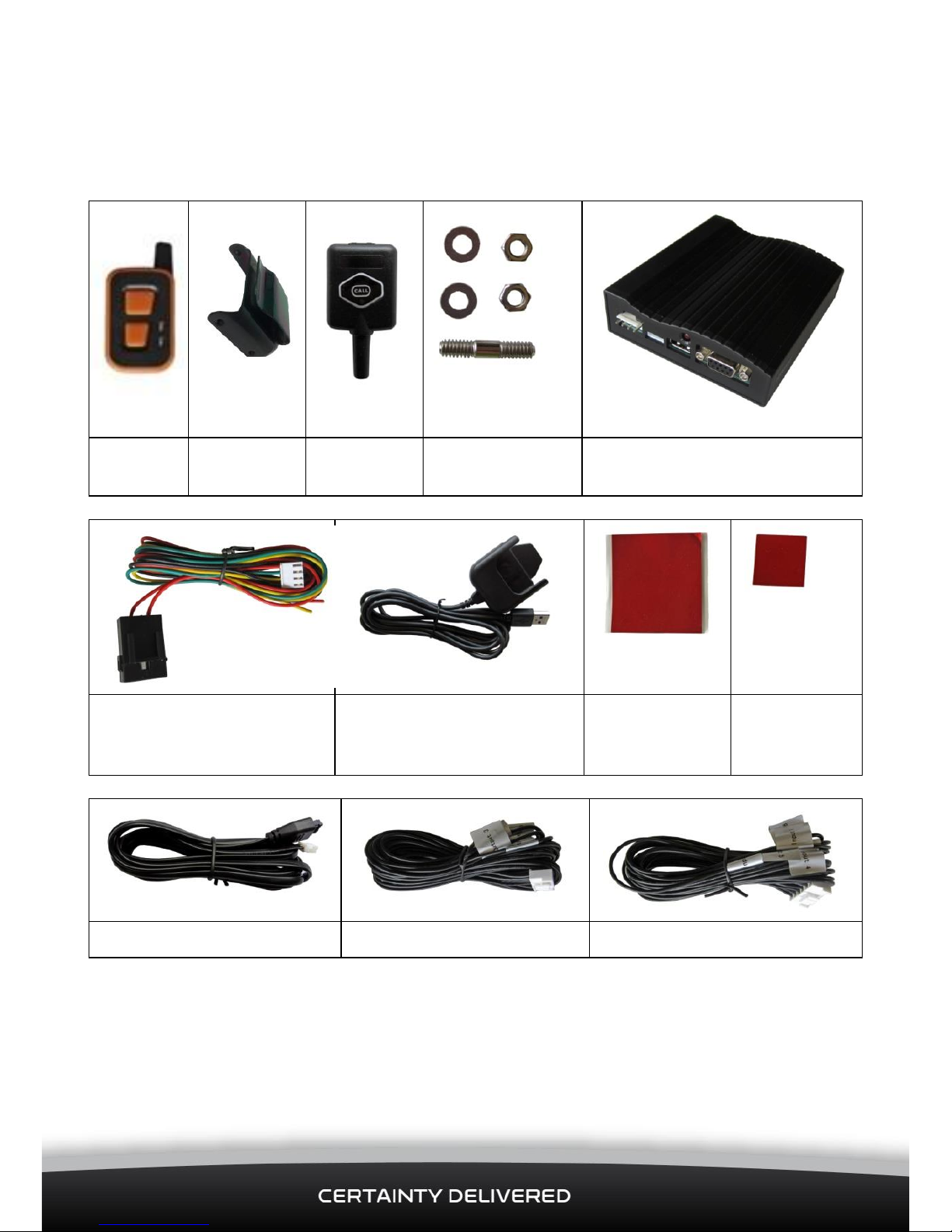
1.3 Box Contents
Check that all of the following items were supplied in the gift box.
If anything is missing, please contact your Navman Wireless dealer.
Pendant
Belt Clip
Antenna
Charging Dock
Mounting Kit
Interface Module
Main Power Harness with
2 Amp fuse
Charging Dock with cable
Interface
Module
Adhesive Pad
Antenna
Adhesive Pad
Antenna Cable
5-Wire Output Cable
6-Wire Input Cable
A
Lone Worker Solution User Guide
is also included, in addition to this installation manual.
Page 7

Lone Worker Solution | Installation Manual
7
2 Installation
2.1 Prerequisites
This installation process assumes that:
A Qube is already installed in the vehicle and is fully operational. If not, please
install the Qube according to its install guide BEFORE starting the Lone Worker
Solution installation. Note that the Lone Worker Solution is compatible with any
Qube that has sufficient digital I/O available. Depending on the mode used, the
Lone Worker Solution requires 2 or 4 digital inputs and 1 digital output.
The Qube already has a suitable ConEx cable installed. If not, please obtain this
cable from your Navman Wireless dealer in order to complete the Lone Worker
Solution installation.
The Qube and AVL2 are correctly configured for the Lone Worker Solution
The “Ack Back” and alerting system has been activated
2.2 Installation Overview
Navman Wireless recommend that you install the Lone Worker Solution components in the
order shown below:
Mount the Antenna, Charging Dock, and Interface Module.
Connect the Antenna to the Interface Module.
Connect the Charging Dock to the Interface Module.
Connect the Interface Module to the vehicle ignition loom (or fuse box) through
a constant 12 V battery supply.
Connect the Interface Module to the Qube.
(Optional) Connect the relay drive output to the vehicle’s lights and horn.
Put the Pendant into the Charging Dock so that the Pendant’s internal battery
can start to charge, ready for testing, as soon as you have connected the
Interface Module.
Test the Pendant and the Antenna.
Navman Wireless recommend that you read this entire section BEFORE starting.
Page 8

Lone Worker Solution | Installation Manual
8
CAUTION
Ensure that any holes that need to be cut in the vehicle will not weaken the vehicle
structure or compromise the safety of the vehicle or its occupants. If in doubt, consult
the vehicle manufacturer.
Consult the vehicle owner and agree on the proposed mounting locations for the
Interface Module, Antenna, and Charging Dock BEFORE cutting any holes in the vehicle.
Where holes are required, use grommets to ensure that the vehicle remains waterproof.
2.3 Find the Qube
You need to install the Interface Module close to the Qube, so find the Qube. This is
usually behind the vehicle’s dash but it may be in the boot/trunk area.
Check that the cables are long enough to reach comfortably between the Qube, the vehicle
ignition loom (or fuse box) and proposed locations for the Interface Module, Antenna, and
Charging Dock which are described in the following sections.
If the cables are not long enough, you need to supply:
a 5-Core cable extension to cover the Digital Inputs/Output (see section 3.2)
between the Qube and the Interface Module
a 5-Core cable extension to connect the Antenna to the Interface Module (see
section 2.7).
2.4 Mount the Antenna
CAUTION
The Antenna must be located at least 20 cm (8”) from any person to meet FCC RF
exposure requirements.
1. Sit in the driver’s seat and choose a location along the top of the windscreen. The
Antenna MUST be mounted on the windscreen and within easy reach of the driver.
Note:
A suitable location is usually near to the A pillar so that the cable can be hidden
behind the interior panels.
2. Clean any dust and grease from the chosen location area.
3. Remove the backing tape from one side of the Antenna Adhesive Pad and press the
pad firmly to the windscreen.
4. Peel the backing tape from the other side of the Antenna Adhesive Pad.
5. Orient the Antenna so that the mast points DOWN and the CALL button is the right
way up, then press the back of the Antenna firmly onto the Antenna Adhesive Pad.
Page 9

Lone Worker Solution | Installation Manual
9
2.5 Mount the Charging Dock
Choose a suitable mounting location on the dashboard, such as a spare accessory blanking
plate, where the Charging Dock will not interfere with the safe operation of the vehicle.
If a spare accessory blanking plate is available, remove this and run the USB cable through
the hole.
If a spare accessory blanking plate is NOT available, Navman Wireless recommend that
you run the USB cable between two panels on the dashboard.
Drill a hole only when this is unavoidable.
2.5.1 Interface Module Connections
Identify the connectors on the Interface Module:
Front
Back
2.6 Mount the Interface Module
The Interface Module mounting location must:
NOT be visible to the lone worker or any other vehicle driver,
be a flat rigid surface where the Interface Module can be firmly secured,
be close to the Qube so that the 5-Wire Output Cable and 6-Wire Input Cable
can connect comfortably,
5-Pin Output Cable
NOT USED
NOT USED
6-Pin Input Cable
Power
Antenna
Charging Dock
Power LED
FUTURE USE
Page 10

Lone Worker Solution | Installation Manual
10
allow easy access to both the front and back of the Interface Module,
be dry and not be subject to excessive vibration or excessive heat.
Mount the Interface Module at the chosen location as follows:
1. Clean any dust and grease from the chosen mounting location.
2. Remove the backing tape from one side of the Interface Module Adhesive Pad and
press the pad firmly to the chosen mounting location on the vehicle.
3. Peel the backing tape from the other side of the Interface Module Adhesive Pad.
4. Press the back of the Interface Module firmly onto the Interface Module Adhesive Pad.
5. Secure the Interface Module in place with cable ties.
2.7 Connect the Antenna to the Interface Module
1. Find the Antenna cable.
2. Push the black end into the cable port at the top of the Antenna.
3. Run the Antenna cable behind the interior panel by the A pillar, to the Interface
Module. Secure the Antenna cable tidily using wire cable ties.
4. Push the white end into the Antenna port on the front of the Interface Module. It
clicks into place.
2.8 Connect the Charging Dock to the Interface Module
1. Run the Charging Dock cable discreetly between the dashboard panels to the
Interface Module. Make sure that Charging Dock cable is flush against the surface,
with no cable loops or similar that could snag and dislodge the cable in the future.
2. Secure the Charging Dock cable using wire cable ties.
3. Push the USB connector into the USB port on the front of the Interface Module.
Page 11

Lone Worker Solution | Installation Manual
11
3 Wiring
3.1 Before Starting
CAUTION
Any connection to the vehicle’s wiring system must not interfere with the operation of
the vehicle or with any of the vehicle’s safety systems. If in doubt, consult the vehicle
manufacturer.
Incorrect wiring or exposed bare wires may result in electrical damage to the Interface
Module, Antenna, or the vehicle’s wiring system. Use insulation tape to insulate any bare
unconnected wires.
Make sure that all cables are:
tidily secured with wire cable ties, and do not present a hazard to vehicle
occupants,
protected from chaffing on sharp edges,
connected to manufacturer’s approved points,
located where they will not be damaged.
3.2 Connect the Interface Module to the Qube
The Qube has several Digital Input and Digital Output lines which can be connected to
external sensors or equipment, such as the Lone Worker Solution, through Qube’s ConEx
system.
You can connect the Interface Module to the Qube using either:
single output mode (default), where the High Priority Alert, Person Down
Alert, and Out of Range warning share the same Digital Output line OR
multi-output mode, where the High Priority Alert, Person Down Alert, and
Out of Range warning each have a separate Digital Output line.
IMPORTANT
If the Qube I/O cable is already installed and connected to other external sensors or
equipment, contact the Navman Wireless Technical Support Team for advice before
proceeding.
3.2.1 Single Output (Default) Wiring
This is the default option. The High Priority Alert, Person Down Alert, and Out of Range
warning share the same Digital Output line in the 5-Wire Output Cable. To use this option:
Page 12

Lone Worker Solution | Installation Manual
12
1. Push the 5-Wire Output Cable firmly onto the 5-Pin Output at the back of the
Interface Module. Check that the toggle on the white connector has latched into place.
2. Connect the individual output wires at the other end of the 5-Wire Output Cable to the
Qube’s I/O cable, as follows:
Note – the colours shown below relate to a Qube 4 10-way connector
Output
Wire
ConEx
Qube
Pin
Qube Wire
Colour
Function
1
DI-3
6
Blue
High Priority Alert (this also Wakes the Qube
From Sleep), Person Down Alert, Out of Range
Warning
2
DI-1
8
Green/White
NOT USED
3
DI-2
7
Blue/White
NOT USED
4
(Optional). If connected through a 200 mA
Relay Drive, the vehicle’s lights flash and horn
sounds when a High Priority Alert or an Out of
Range warning is generated.
5
DI-4
5
Purple
Check In
3.2.2 Multi-Output Wiring
In this wiring option, the High Priority Alert, Person Down Alert, and Out of Range warning
each use a separate Digital Output line in the 5-Wire Output Cable. To use this option:
1. Ensure that the Lone Worker Solution has been set into Multi Output mode.
2. Push the 5-Wire Output Cable firmly onto the 5-Pin Output at the back of the
Interface Module. Check that the toggle on the white connector has latched into place.
3. Connect the individual output wires at the other end of the 5-Wire Output Cable to the
Qube’s I/O cable, as follows:
Note – the colours shown below relate to a Qube 4 10-way connector
Output
Wire
ConEx
Qube
Pin
Qube Wire
Colour
Function
1
DI-3
6
Blue
High Priority Alert (this also Wakes the Qube
From Sleep)
2
DI-1
8
Green/White
Person Down Alert
3
DI-2
7
Blue/White
Out of Range Warning
4
(Optional). If connected through a 200 mA
Relay Drive, the vehicle’s lights flash and
horn sounds when a High Priority Alert or an
Out of Range warning is generated.
5
DI-4
5
Purple
Check In
Page 13

Lone Worker Solution | Installation Manual
13
3.2.3 Input Wiring
1. Push the 6-Wire Input Cable firmly onto the 6-Pin Input at the back of the Interface
Module. Check that the toggle on the white connector has latched into place.
2. Connect Input Wire 1 at the other end of the 6-Wire Input Cable to the Qube’s I/O
cable, as follows:
Note – the colours shown below relate to a Qube 4 10-way connector
Input Wire
ConEx
Pin (Qube)
Wire Colour (Qube)
Function
1
DO-1
9
Light Green
Alert Acknowledgement
2 - 6
NOT USED
The Digital Output will pull to Ground and sink a maximum current of 250 mA when
activated.
The Digital Output has over-current trip protection and, if tripped, must be changed to OFF
or have a power cycle to reset the current trip.
3.3 Connect the Interface Module to the Ignition Loom or Fuse
Box
The Red wire on the Main Power Harness is supplied with a 2 Amp fuse.
Push the white connector on the end of the Main Power Harness into the power connector
on the front of the Interface Module. Check that the toggle on the white connector has
latched into place..
Connect ONLY the Black wire and the Red Wire to the vehicle ignition loom as follows:
Pin
Wire Colour
Function
Description
1
Black
Negative/GND
Vehicle Ground/chassis connection.
2
Yellow
OBDII
Not Used
3
Green
OBDII
Not Used
4
Red
+9/36 V DC
Main power connection (main vehicle supply)
on 12 / 24 V vehicles. The Main Power Harness
already has a 2 Amp fuse. The Red wire MUST
be connected to the SAME main power
connection as the Qube to enable the Lone
Worker Solution to operate while the vehicle is
parked with Ignition OFF. This includes isolated
vehicles and vehicles with an IPS.
Page 14

Lone Worker Solution | Installation Manual
14
4 Commission Testing
4.1 Configuration and Activation of Lone Worker Solution
Verify with Navman Wireless Technical Support that the Qube has been correctly
configured for connection to the Lone Worker Solution.
Verify with Navman Technical Support that the “Ack Back” system has been activated
4.2 Charge the Pendant
1.
Align the Pendant with the Charging Dock, with the buttons
at the front. Push the Pendant firmly into the Charging Dock,
as shown.
The Pendant sounds and ascending/descending tone when it
has docked successfully.
2.
The RED and GREEN LEDs flash alternately once a second
while the battery is charging. This can take up to 2 hours.
3.
When the battery is charged, the GREEN LED slowly fades on
and off. The Pendant remains in a low power state until it is
removed from the Charging Dock.
4.3 Check the Ignition Connection
Check that the Red wire of the Main Power Harness is connected to the same main power
connection as the Qube.
4.4 Test the Pendant High Priority Alert Function
When the Pendant battery is fully charged, check that the Pendant can communicate with
OnlineAVL2 correctly as follows:
1. Park the vehicle outside, in a location with a clear view of the sky and good cellular
coverage.
Note:
If there is no cellular coverage area but the vehicle has a Q-Pro modem, any
High Priority Alerts will be sent by satellite.
2. Log into OnlineAVL2 then call the Navman Wireless Support Team for assistance with
commissioning the Lone Worker Solution for this particular vehicle.
Page 15

Lone Worker Solution | Installation Manual
15
3. Press either button on the Pendant and a beep will sound. Hold the button for
approximately 1 second until a second beep is heard, then release. The Pendant then
tries to send a High Priority Alert.
4. If the High Priority Alert was sent successfully, the Pendant should receive an Alert
Acknowledgement from back office within 3 minutes. (The length of time depends on
the cellular or satellite network.)
The Interface Module beeps once and the Pendant beeps (ascending and descending)
and vibrates 3 times to confirm that your Alert has been received by back office.
The Pendant repeats this sequence once.
5. Verify with Technical Support that the event has been received.
4.5 Test the Person Down Alert Function
1. Check that you are still logged into OnlineAVL2 and, if not, log in again.
2. Exit the vehicle then throw the Pendant up in the air for at least 100 cms (3 feet). Be
sure to catch the Pendant before it hits the ground, to avoid damage to the Pendant.
The sudden movement should trigger a Person Down Alert.
3. The Pendant warbles and illuminates the green LED for 10 seconds then sends a
Person Down Alert.
4. If the Person Down Alert was sent successfully you will receive an Alert
Acknowledgement from back office.
5. Verify with Technical Support that the event has been received.
4.6 Test the Pendant Check In Function
1. Check that you are still logged into OnlineAVL2 and, if not, log in again.
2. Double press either button. The Pendant beeps once for each press then tries to send
a Check In message.
3. Verify with Technical Support that the event has been received.
4. You will not receive an Alert Acknowledgment.
4.7 Test the Antenna Alert Function
1. Hold the CALL button on the Antenna for 1 second then release.
2. The Interface Module sounds a noise to confirm that the High Priority Alert has been
sent.
3. Verify with Technical Support that the event has been received.
Page 16

Lone Worker Solution | Installation Manual
16
4.8 Test the Out of Range Warning
Perform this test ONLY for a Multi-Output Wiring installation (see section 3.2.2).
1. Simulate that the Pendant has been moved out of range by unplugging the power
from the interface module.
2. After a few seconds the Pendant detects that it has lost communication with the
interface module and sounds 3 long warning beeps and vibrates 3 times. It also
flashes the RED LED twice every 20 seconds.
3. Reconnect power to simulate the Pendant moving back in range so that it returns to
normal operation – it should start to flash the green LED every 10 seconds
4.9 Handover
When you have completed all the tests and confirmed with the Navman Wireless Support
Team that the Lone Worker Solution is working correctly, please:
1. Leave the
Lone Worker Solution User Guide
in the vehicle where it can be seen easily
by the lone worker (e.g. on the driver’s seat).
2. Leave the Pendant ON and place it in the battery charger, ready for use by the lone
worker.
4.10 Troubleshooting
4.10.1 Alert or Check In Not Shown in AVL2
If an Alert or a Check In is not shown in the client, try the following:
Check that all of the cables are connected correctly and are secure.
Check that the Interface Module is connected correctly so that it is powered.
Check that the GREEN LED on the Pendant is flashing once every 10 seconds
(this shows the Pendant is paired correctly with Interface Module).
Confirm that the Qube 4 is awake with cellular communications operating
correctly by contacting the Navman Wireless Support Team and asking if the
vehicle is shown as online in OnlineAVL2 (IGN on).
Confirm with Technical support that the Qube is set up with the correct ConEx
configuration and satellite prioritisation for ConEx (if satellite modem is being
used)
4.10.2 Alert Acknowledgement is not Received
If the alert acknowledgement is not received by the Pendant, :
Check that all of the cables are connected correctly and are secure.
Verify with Technical Support that “Ack Back” is enabled.
Page 17

Lone Worker Solution | Installation Manual
17
5 Configuring the System
The Lone Worker Solution should be already set up correctly for the particular customer
and installation requirements. Check with Navman Wireless Technical Support before
making any configuration changes.
5.1 To Configure the Lone Worker System
1. Ensure the Pendant is working and communicating with the vehicle
2. Press and hold both buttons for 5 seconds until you hear the ascending tones.
3. Press the lower button the required number of times to set the required configuration
setting (see below).
4. When the required number of presses have been entered, wait for the Pendant to
respond with a sequence of beeps – one for each button press.
5. The system will now adopt the new setting
5.2 Configuration Settings
The number of button presses for each config setting are as follows:
3 – Wait for application Ack (default)
4 – Do not wait for application Ack
5 – Multi Output mode
6 – Single Output mode (default)
7 – Accelerometer ON (default)
8 – Accelerometer OFF
9 – un-pair Pendant
10 – Get FW version
11 – Impact setting is 1.5G (default)
12 – Impact setting is 2.0G
13 – Impact setting is 2.5G
14 – Impact setting is 3.0G
15 – Impact setting is 3.5G
17 – Freefall detect is OFF
18 – Freefall detect is 1m
19 – Freefall detect is 2m (default)
20 – Motion detect after man down event is OFF (default)
21 – Motion detect after man down event is 5s
22 – Motion detect after man down event is 10s
23 – Return Pendant to default settings (i.e. options 7, 11, 19, 20)
Page 18

Lone Worker Solution | Installation Manual
18
6 Contacts
Navman Wireless UK
Innovation Centre 2, Keele University Science
Park, Staffordshire, ST5 5NH, UK
Tel: +44 (0) 1782 55 79 50
Fax: +44 (0) 1782 55 79 79
Email: support@navmanwireless.co.uk
Website: www.navmanwireless.co.uk
Navman Wireless USA
2701 Patriot Boulevard, Suite 150
Glenview, IL 60026, USA
Tel: +1 (866) 527-9896
Fax: +1 (847) 729-5988
Email: us.support@navmanwireless.com
Website: www.navmanwireless.com
Navman Wireless Australia
Ground Floor, 16 Giffnock Avenue
Macquarie Park NSW 2113, Sydney, Australia
Tel: +61 2 9886 8500
Fax: +61 2 9887 2481
Email: info@navmanwireless.com.au
Website: www.navmanwireless.com.au
Navman Wireless NZ
7-11 Kawana Street, Northcote,
PO Box 340-184, Birkenhead 0746
Auckland, New Zealand
Tel: 0800 GPS FLEET (0800 477 353)
Email: info.nz@navmanwireless.com
Website: www.navmanwireless.co.nz
Navman Wireless Scandinavia
Kometvej 10, DK-6230, Rødekro, Danmark
Tel: Danmark: +45 70 269 732
Tel: Sweden: +46 8 559 21 916
Tel: Finland: +35 89 2316 3595
Navman Wireless Italy
Via Rudone 23rd, Rovato 25,038, Italia
Tel: +39 030 615 6468
Website: www.navmanwirelessitaly.it
Navman Wireless Taiwan
#3, 25Fl., No.508, Sec.5 Zhongxiao E. Rd,
Dist. Taipei 110, 11083, Taiwan
Tel: +886 0 2 2728 2818
Fax: +886 0 2 2728 2816
Email: support_tw@navmanwireless.com
Website: www.navmanwireless.com.au
Navman Wireless China
#911, No. 83, New Town Center,
Loushanguan Rd, Changning District,
Shanghai, 200336, China
Tel: +86 0 21 3218 1056
Fax: + 86 0 21 3218 1052
Email: support_cn@navmanwireless.com
Website: www.navmanwireless.cn
Navman Wireless de México
Calzada San Pedro #100, Col. del Valle,
Pedro Garza García, Nuevo Léon. CP 66220,
México
Teléfono: +52(81) 8248.4600 ext 1001
Email: soporte@navmanwireless.com
Website: www.navmanwireless.com.mx
Lone Worker Solution Installation Manual (October 2014)
 Loading...