

Page 1
NAVMAN
www.navman.com
Installation Manual
English .............. 3
Español............. 7
Português ....... 10
GPS 1240/1330
A N T E N N A
Page 2

Industry Canada
Operation is subject to the following two conditions: (1) this device may not cause
interference, and (2) this device must accept any interference, including interference that may cause undesired operation of the device.
Page 3

3GPS 1240/1330 antenna installation manual
NAVMAN
FCC Statement
Note: This equipment has been tested and found to comply with the limits for a Class
B digital device, pursuant to Part 15 of the FCC Rules. These limits are designed to
provide reasonable protection against harmful interference in a normal installation.
This equipment generates, uses and can radiate radio frequency energy and, if not
installed and used in accordance with the instructions, may cause harmful interference
to radio communications. However, there is no guarantee that interference will not
occur in a particular installation. If this equipment does cause harmful interference to
radio or television reception, which can be determined by turning the equipment off
and on, the user is encouraged to try to correct the interference by one or more of the
following measures:
Reorient or relocate the receiving antenna
Increase the separation between the equipment and receiver
Connect the equipment into an output on a circuit different from that to which the
receiver is connected
Consult the dealer or an experienced technician for help
A shielded cable must be used when connecting a peripheral to the serial ports
Important
It is the owner’s sole responsibility to install and use the antenna in a manner that will not cause
accidents, personal injury or property damage. The user of this product is solely responsible for
observing safe boating practices.
Global Positioning System: The Global Positioning System (GPS) is operated by the US
government which is solely responsible for its operation, accuracy and maintenance. The GPS
system is subject to changes which could affect the accuracy and performance of all GPS
equipment anywhere in the world.
Installation: If installation is not correct, the unit can not perform at its designed potential. If in
doubt, consult your Navman dealer. Ensure that any holes made are in a safe position and will
not weaken the boat’s structure. If in doubt, consult a qualifi ed boat builder.
NAVMAN NZ LIMITED DISCLAIMS ALL LIABILITY FOR ANY USE OF THIS PRODUCT IN A
WAY THAT MAY CAUSE ACCIDENTS, DAMAGE OR THAT MAY VIOLATE THE LAW.
Governing language: This statement, any instruction manuals, user guides and other information
relating to the product (Documentation) may be translated to, or has been translated from,
another language (Translation). In the event of any confl ict between any Translation of the
Documentation, the English language version of the Documentation will be the offi cial version
of the Documentation.
This manual represents the installation procedures as at the time of printing. Navman NZ Limited
reserves the right to make changes to specifi cations without notice.
Copyright © 2004 Navman NZ Limited, New Zealand, all rights reserved. Navman is a registered
trademark of Navman NZ Limited.
Page 4
4
NAVMAN
GPS 1240/1330 antenna installation manual
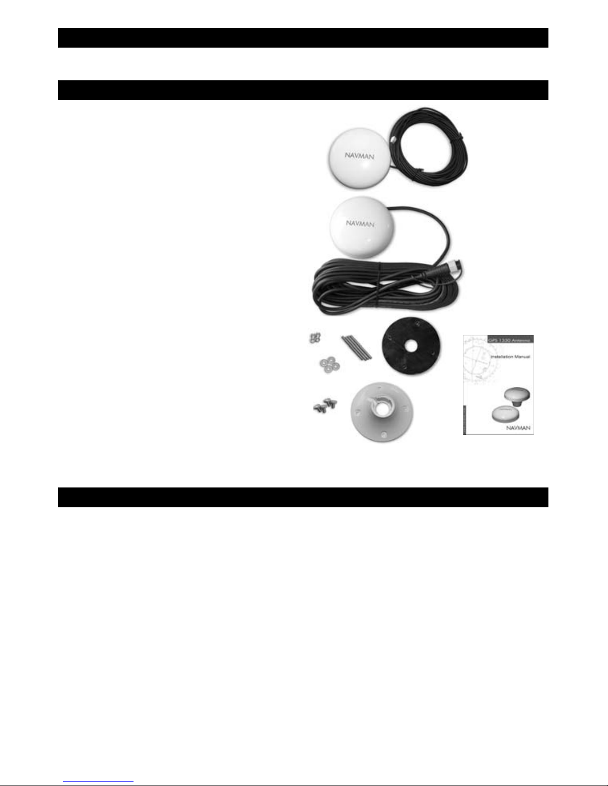
GPS 1240: includes 10 m (32.8 ft) cable
or
GPS 1330: includes 5 m (16.6 ft) cable
This installation guide
For surface mounting:
Gasket (doubles as mounting template)
4 threaded rods: thread M4 x 40 mm (2")
4 washers
4 nuts
For pole mounting:
Pole mount adaptor
4 screws
Also available:
GPS 1240: 10 m (32.8 ft) extension cable
GPS 1330: 5 m (16.6 ft) extension cable (Note:
only one extension cable may be used)
1 Introduction
What comes with your GPS 1240 or 1330 antenna
This installation manual describes how to install Navman’s GPS 1240/1330 antenna using two
methods: surface mounting and pole mounting.
2 Choosing a suitable location for the antenna
Mount the antenna with a good view of the sky
and horizon. The view should not be blocked
by large parts of the superstructure.
The unit can be under glass, perspex, fi breglass
or fabric, but not under metal or wood.
Mount the antenna away from any source of
electrical signals or noise. Do not mount the
antenna within 3 m (10 ft) of a radio transmitter
antenna or within 0.5 m (20") of the plane of a
radar antenna.
Do not fi t the antenna too high, such as up a
mast, or boat rocking will cause errors in speed
and bearing.
Do not mount the antenna where it can be
used as a hand hold, where it will interfere
with the operation of the boat or where it might
be submerged.
Mount the antenna within the connection range
of the cable in it's fi nal secured position, keeping
the cable away from sources of electrical
signals or noise and ensuring the cable is not
pinched or crushed.
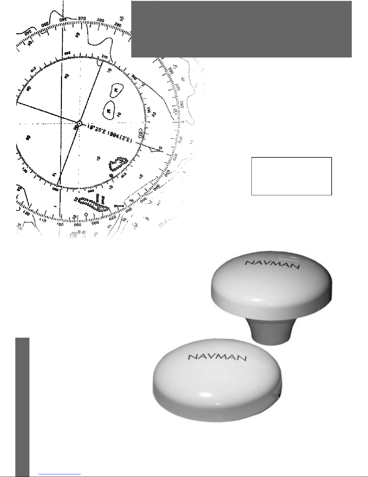
GPS 1330
GPS 1240
Page 5
5GPS 1240/1330 antenna installation manual
NAVMAN
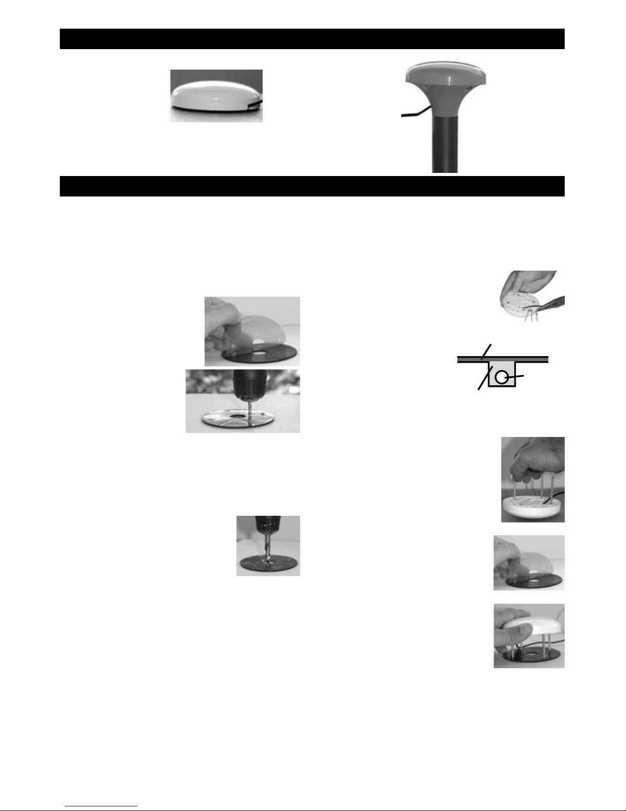
4B If exiting the side of the
antenna, remove three
plastic tabs, then seal
cable into place with
silicon.
Ensure that the
channel is fi lled
with silicon to
provide a seal
when gasket is
in place.
5. Attach the four threaded
pins to the antenna.
6. Peel the plastic off the
gasket.
7. Place antenna in fi nal
position.
8. Attach the four nuts to the threaded rod.
Do not overtighten.
9. Attach to instrument, then secure the
cable at regular intervals.
3-1 Surface mounting
Select a suitable location which allows access for affi xing nuts and has a suitable mounting surface.
Avoid high traffi c areas where the antenna may be a tripping hazard.
Ensure that any holes made are in a safe position and will not weaken the boat’s structure. If in
doubt, consult a qualifi ed boat builder.
3 Mounting
There are two mounting options:
Pole mountedSurface mounted
1. Clean the surface where the antenna will
be mounted.
2. Peel the back off one
side of the gasket
and stick the gasket
in the fi nal mounting
position.
3. Using the gasket
as a template, drill
four 4 mm (5/32")
holes.
4. The cable may either pass through the
surface the antenna is mounted on, or
exit the side of the antenna:
4A For GPS 1330 if
passing cable through
the surface, drill a 9
mm (3/8") hole for the
connector.
For GPS 1240 if
passing cable through
the surface, drill an 18 mm
(23/32") hole for the
connector.
Fill with
silicon
Gasket
Page 6

6
NAVMAN
GPS 1240/1330 antenna installation manual
Clean the antenna with a damp cloth or mild
detergent. Avoid abrasive cleaners, petrol or
other solvents.
When repainting the surrounding area, cover the
antenna with masking to protect from paint. Do
not paint the antenna.
3-2 Pole mounting
Note: Do not mount the antenna too high, such as
up a mast, or boat rocking will cause errors in speed
and bearing.
Attach only to 1" (25.4 mm) diameter pole with a thread
of 14 TPI UNB.
Thread the cable through the pole mount adaptor.
Position the pole mount adaptor onto the antenna,
using the positioning tabs.
Attach with the four srews provided, do not overtighten.
The cable may pass through the pole, or exit the side
of the antenna.
Screw onto the pole. Do not overtighten.
Attach to instrument, then secure the cable at regular
intervals.
Technical specifi cations
GPS 1240 GPS 1330**
Weight (with cable): 490 g (16 oz) 225 g (8 oz)
Power supply: via instrument via instrument
Typical power consumption: 30 mA (at 12 V DC) 29 mA (at 6 V DC)
GPS dynamics: 950 m/s (2125 mph)
acceleration 4 G
950 m/s (2125 mph)
acceleration 4 G
Operating temperature: 0 to 60°C (32 to 140°F) 0 to 60°C (32 to 140°F)
Re-aquisition times: 2 sec typical (<10 sec
blockage)
2 sec typical (<10 sec
blockage)
TTFF* (warm start): < 38 sec < 38 sec
TTFF* (cold start): < 45 sec < 45 sec
Update rate: Typically every second once fi x
established
Typically every second once fi x
established
Output: NMEA: GGA, RMC, GSA, GSV,
VTG
50 ohms / SMA
Case: UV stable plastic radome UV stable plastic radome
Environment: IP67 IP67
Connector: 8 pin Liang Tei SMA
Notes: *Figures provided for Time To First Fix are for 90% or better for fi rst fi x. ** Performance when connected to a Navman chartplotter
4 Cleaning and maintenance
Positioning tabs
Page 7
7Manual de Instalación Antena GPS 1330
NAVMAN
GPS 1330
GPS 1240
GPS 1240: La antena GPS incluye un cable 10 m (32.8 pies).
GPS 1330: La antena GPS incluye un cable 5 m (16.6 pies).
Esta guía de instalación
Para el montaje sobre superfi cie:
Junta de estanqueidad (doble como plantilla
de montaje)
4 varillas roscadas: rosca M4 x 40 mm (2”)
4 arandelas
4 tuercas
Para montaje sobre poste:
Un adaptador de montaje para poste
4 tornillos
También disponible:
GPS 1240: Alargo 10 m (32.8 pies)
GPS 1330: Alargo 5 m (16.6 pies)
(Nota: un solo alargo se puede utilizar).
1 Introducción
Qué se entrega con la antena GPS 1330
Este manual describe dos métodos posibles de instalación de la antena GPS 1330 Navman: el
montaje sobre superfi cie y el montaje sobre poste.
2 Elección de un emplazamiento correcto para la antena
Montar la antena de forma que disponga de
una vista despejada del cielo y del horizonte.
La vista no debe ser impedida por partes de
la estructura.
La unidad se puede colocar debajo de vidrio,
perspex, fi bra de vidrio o tejido pero NO
debajo de metal o madera.
Montar la antena alejada de cualquier fuente
de señales o turbulencias eléctricas. Montar la
antena al menos a 3 m (10 pies) de la antena
de un transmisor radio o al menos a 0,5 m
(20”) del haz de una antena radar.
No montar la antena demasiado alto, por
ejemplo, en un mástil, ya que el balanceo
del barco podría causar errores en las
indicaciones de la velocidad y del rumbo.
No montar la antena en lugares donde se
podría confundir con pasamanos, donde
podría interferir con el buen funcionamiento
del barco o donde podría sumergirse.
Montar la antena de forma que el cable no
tenga tensiones, esté colocado de manera
segura, esté alejado de cualquier fuente de
señales o turbulencias eléctricas y asegurarse
que este cable no esté aplastado o pillado.
Page 8

8
NAVMAN
Manual de Instalación Antena GPS 1330
4B Si el cable sale por
la parte lateral de la
antena, sacar
las 3 lengüetas
de plástico,
luego sellar
el cable con
silicona.
Asegurarse
que el cono
esté lleno de
silicona una vez colocada la junta de
estanqueidad.
5. Colocar las cuatro patillas
de rosca a la antena.
6. Sacar el fi lm de
plástico de la junta de
estanqueidad.
7. Colocar la antena en su
posición defi nitiva.
8. Colocar las cuatro tuercas a la varilla de
rosca. No apretar demasiado.
9. Colocar al instrumento, luego asegurar el
cable a intervalos regulares.
3-1 Montaje sobre superfi cie
Escoger un emplazamiento adecuado que permite acceder a las tuercas de fi jación y que dispone
de una superfi cie sufi ciente para el montaje. Evitar las zonas donde la antena podría estorbar.
Asegurarse que todos los taladros se efectuarán de forma segura y que no afectarán la estructura
del barco. En caso de cualquier duda, por favor contactar con su distribuidor Navman.
3 Montaje
Existen dos opciones de montaje:
Montaje sobre
poste
Montaje sobre
superfi cie
1. Limpiar la superfi cie de montaje.
2. Sacar el fi lm plástico
de la junta de
estanqueidad y
pegar la junta en su
posición defi nitiva.
3. Utilizar la junta
como plantilla,
taladrar 4
agujeros de 4 mm
(5/32”).
4. El cable puede pasar o bien por la
superfi cie de montaje de la antena, o salir
por la parte lateral de la antena.
4A En el GPS 1330, si
desea pasar el cable
por la superfi cie, realice
un orifi cio de 9 mm
(3/8”) para el conector.
En el GPS 1240, si desea pasar el
cable por la superfi cie, realice un
orifi cio de18 mm (23/32”) para el
conector.
Llenar de
silicota
Junta de estanqueidad
Cable
Page 9

9Manual de Instalación Antena GPS 1330
NAVMAN
Especifi caciones técnicas
Limpiar la antena con un paño húmedo o
un detergente suave. Evitar los limpiadores
abrasivos, petróleo u otros solventes.
En caso de pintar el área cercana a la antena,
proteger la antena con enmascaramiento. No
pintar la antena.
3-2 Montaje sobre poste
Nota: No montar la antena demasiado alto, por
ejemplo, en un mástil, ya que el balanceo del
barco podría causar errores en la velocidad
y el rumbo.
Colocar a un poste de 25,4 mm de diámetro
con una rosca de 14 TPI UNB.
Ensartar el cable por el adaptador de montaje
del poste.
Colocar el adaptador de montaje del poste
sobre la antena, utilizando las lengüetas de
colocación. Asegurar mediante los cuatro
tornillos previstos, no apretar demasiado.
Unir con los cuatro tornillos proporcionados,
No apretar demasiado.
El cable puede pasar por el poste o salir por
la parte lateral de la antena.
Atornillar al poste. No apretar demasiado.
4 Limpieza y mantenimiento
Lenguëtas de colocación
Colocar al instrumento, luego asegurar el
cable a intervalos regulares.
GPS 1240 GPS 1330**
Peso (con cable): 490 g (16 oz) 225 g (8 oz)
Alimentación: Vía el instrumento Vía el instrumento
Consumo eléctrico típico: 30 mA (a 12 V DC) 29 mA (a 6 V DC)
Dinámica GPS 950 m/s (2125 mph) aceleración 4 G 950 m/s (2125 mph) aceleración 4 G
Temperatura de funcionamiento:
0 to 60°C (32 to 140°F) 0 to 60°C (32 to 140°F)
Tiempo de re-adquisición de
señal:
2 segundos típicos (<10 seg
congestión)
2 segundos típicos (<10 seg
congestión)
TTFF* (Tiempo de adquisición
del primer fijo (arranque en
caliente):
< 38 seg < 38 seg
TTFF* (Tiempo de adquisición del
primer fi jo (arranque en frío):
< 45 seg < 45 seg
Coefi ciente de actualización: Típicamente cada segundo una vez
establecido el primer fi jo de posición
Típicamente cada segundo una vez
establecido el primer fi jo de posición
Salida: NMEA: GGA, RMC, GSA, GSV, VTG 50 ohmios / SMA
Caja: Protección de plástico UV estable Protección de plástico UV estable
Entorno: IP67 IP67
Conectador: 8 pin Liang Tei SMA
Notas: Las cifras proporcionadas para “Tiempo hasta la primera reparación” (Time To First Fix o TTFF) son para 90% o más para la primera
reparación ** Resultado cuando se conecta a un trazador de mapas Navman.
Page 10

10
NAVMAN
Manual de instalação da antena do GPS 1240/1330
Importante
É de exclusiva responsabilidade do proprietário instalar e utilizar a antena de forma a não
causar acidentes, ferimentos a pessoas ou danos a propriedades. O utilizador deste produto
é o único responsável pelo cumprimento de práticas seguras de navegação.
Sistema de Posicionamento Global: O Sistema de Posicionamento Global (GPS) é operado
pelo governo dos EUA, que é o responsável exclusivo por seu funcionamento, precisão e
manutenção. O sistema GPS está sujeito a alterações que podem afectar a precisão e o
desempenho de todos os equipamentos GPS ao redor do mundo.
Instalação: Se a instalação não for feita de maneira correcta, a unidade poderá não funcionar
em seu pleno potencial. Se estiver em dúvida, consulte o representante Navman. Assegurese de que quaisquer furos estejam em uma posição segura e que não enfraqueçam a
estrutura do barco. Se estiver em dúvida, consulte um construtor de barcos capacitado.
A NAVMAN NZ LIMITED REJEITA QUALQUER RESPONSABILIDADE POR QUALQUER
UTILIZAÇÃO DESTE PRODUTO DE MANEIRA QUE POSSA PROVOCAR ACIDENTES,
DANOS OU QUE POSSA VIOLAR A LEGISLAÇÃO.
Idioma prevalecente: Esta declaração, quaisquer manuais de instrução, guias de utilizadores
e outras informações relacionadas ao produto (Documentação) podem ser traduzidos de e
para qualquer outro idioma (Tradução). No evento de quaisquer confl itos entre qualquer
Tradução da Documentação, a versão da Documentação no idioma Inglês será considerada
como a versão ofi cial da Documentação.
Este manual representa os procedimentos de instalação como eram no momento de
sua impressão. A Navman NZ Limited reserva-se o direito de efectuar alterações nas
especifi cações sem aviso prévio.
Copyright © 2004 Navman NZ Limited, Nova Zelândia, todos os direitos reservados. NAVMAN
é uma marca comercial registada da Navman NZ Limited.previo aviso.
Page 11

11Manual de instalação da antena do GPS 1240/1330
NAVMAN
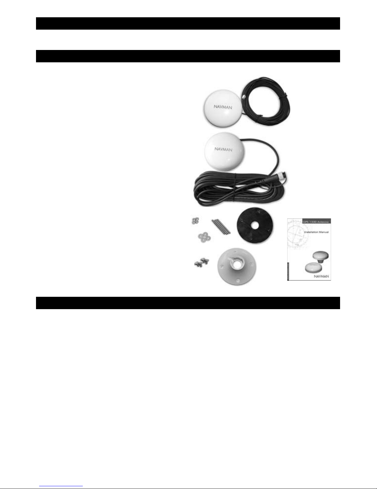
Antena GPS 1240: inclui 10 m (32,8 pés) de cabo
Antena GPS 1330: inclui 5 m (16,6 pés) de cabo
Este guia de instalação
Para montagem na superfície:
Gaxeta (duas, como gabarito de montagem)
4 hastes rosqueadas: rosca M4 x 40 mm (2")
4 arruelas
4 porcas
Para montagem em mastro:
Adaptador para montagem em mastro
4 parafusos
Também disponível:
GPS 1240: Cabo de extensão de 10 m (32,8 pés)
GPS 1330: Cabo de extensão de 5 m (16,6 pés)
(Nota: pode ser utilizado somente um cabo de
extensão).
O que acompanha a sua antena GPS
GPS 1330
GPS 1240
1 Introdução
Este manual de instalação descreve como instalar a antena GPS 1240/1330 da Navman, utilizando
dois métodos:
2 Escolha um local adequado para a antena
Monte a antena em local com boa visão do céu
e do horizonte. A visão não deve ser obstruída
por grandes peças da superestrutura.
A unidade pode fi car abrigada sob cobertura
de vidro, acrílico, fi bra de vidro ou tecido, mas
não sob cobertura metálica.
Monte a antena afastada de qualquer fonte de
sinais ou ruído electrico. Não monte a antena
a menos de 3 m (10 pés) de uma antena
transmissora de rádio ou a menos de 0,5 m
(20”) da superfície de uma antena de radar.
Não instale a antena em local muito alto, como
o topo do mastro, ou o balanço da embarcação
causará erros na velocidade e no rumo.
Não monte a antena em locais em que possa
ser utilizada à guisa de alça, em que possa
interferir com a operação da embarcação ou
onde possa fi car submersa.
Monte a antena dentro da faixa de conexão
do cabo, em sua posição segura defi nitiva,
mantendo o cabo afastado de fontes de sinais
ou ruí
do eléctrico. e assegurando-se de que o
cabo não esteja prensado ou esmagado.
Page 12

12
NAVMAN
Manual de instalação da antena do GPS 1240/1330
4B Se saindo pela lateral
da antena, remova três
abas plásticas e então
lacre o cabo no local com
cola de silicone. Assegure-se de que
a passagem fi que
preenchida com
silicone, para
garantir vedação
quando a gaxeta
estiver afi xada.
5. Prenda os quatro pinos à
antena.
6. Retire o plástico da
gaxeta.
7. Afi xe a antena na posição
fi nal.
8. Prenda as quatro porcas às hastes
rosqueadas. Não aperte em excesso.
9. Fixe o instrumento, a seguir fi xe o cabo
em intervalos regulares.
3-1 Montagem em superfície
Selecione um local apropriado que permita acesso às porcas de fi xação e tenha uma superfície
de montagem apropriada. Evite áreas com tráfego intenso, em que a antena possa representar
um risco para as pessoas.
Assegure-se de que quaisquer furos estejam em uma posição segura e que não enfraqueçam a
estrutura do barco. Se estiver em dúvida, consulte um construtor de barcos capacitado.
3 Montagem
Há duas opções de montagem:
Montagem em
mastro
Montagem em
superfície
1. Limpe a superfície em que a antena será
montada.
2. Raspe a traseira
de um dos lados
da gaxeta e afi xe-a
na posição fi nal de
montagem.
3. Utilizando a
gaxeta como
gabarito, faça
quatro furos de
4 mm (5/32").
4. O cabo pode ser passado através da
superfície em que a antena estiver
montada ou sair pela lateral da antena:
4A Para o GPS 1330, se o
cabo passar através da
superfície, faça um furo
de 9 mm (3/8”) para o
conector.
Para o GPS 1240, se o
cabo passar através da
superfície, faça um furo de
18 mm (23/32”) para o
conector.
Encha com
silicone
Gaxeta
Page 13

13Manual de instalação da antena do GPS 1240/1330
NAVMAN
Especifi cações técnicas
GPS 1240 GPS 1330**
Peso (com o cabo): 490 g (16 onças) 225 g (8 onças)
Fonte de alimentação: via instrumento vvia instrumento
Consumo típico de energia: 30 mA (a 12 V DC) 29 mA (a 6 V DC)
Dinâmica do GPS: 950 m/s (2125 mph/3.419,86km/
h); aceleração de 4 G
950 m/s (2125 mph/3.419,86km/
h); aceleração de 4 G
Temperatura operacional: de 0° a 60°C (32° a 140°F) de 0° a 60°C (32° a 140°F)
Tempos de re-aquisição: 2 segu n dos típi cos (<10
segundos para bloqueio)
2 segundos típicos (<10
segundos para bloqueio)
TTFF* (reactivação): < 38 seg < 38 seg
TTFF* (partida a frio): < 45 seg < 45 seg
Taxa de actualização:
Tipicamente, a cada segundo
assim que estabelecida posição
Tipicamente, a cada segundo
assim que estabelecida posição
Sa ída : NMEA: GGA, RMC, GSA, GSV, VTG 5 0 o hms / S MA
Cobertura: Cúpula plástica estável à
radiação UV.
Cúpula plástica estável à
radiação UV.
Ambiente: IP67 IP67
Conector: 8 pin Liang Tei SMA
Notas: *Os números apresentados para (“Tempo Para Primeira Posição”) sãopara um resultado 90% ou melhor para uma primeira posição.
** Desempenho quando ligado a um traçador de cartas Navman
Limpe a antena com um pano húmido ou com
detergente suave. Evite limpadores abrasivos,
gasolina ou outros solventes.
Quando estiver a pintar a área circundante,
cubra a antena com uma proteção, para evitar
respingos de tinta.
3-2 Montagem em mastro
Nota: Não monte a antena em local muito alto, como
o topo do mastro, ou o balanço da embarcação
causará erros na velocidade e no rumo.
Prenda somente em um mastro com diâmetro
de 1" (25,4 mm), com rosca 14 TPI UNB.
Rosqueie o cabo através do adaptador para
montagem em mastro.
Posicione o adaptador para montagem em
mastro na antena, utilizando as abas de
posicionamento.
Prenda com os quatro parafusos fornecidos,
mas não aperte em excesso.
O cabo pode ser passado através do mastro
ou sair pela lateral da antena:
Aparafuse no mastro. Não aperte em excesso.
4 Limpeza e manutenção
Abas de posicionamento
Fixe o instrumento, a seguir fi xe o cabo em
intervalos regulares.
Page 14

14
NAVMAN
GPS 1240/1330 antenna installation manual
Contacts
NORTH AMERICA
Brunswick New Technologies - Marine Electronics
30 Sudbury Rd, Acton, MA 01720.
Toll Free: +1 866 628 6261
Fax: +1 978 897 8264
e-mail: sales@navmanusa.com
web: www.navman.com
AUSTRALIA
Navman Australia Pty. Limited
Unit 2 / 5-13 Parsons St.
Rozelle, NSW 2039, Australia.
Ph: +61 2 9818 8382
Fax: +61 2 9818 8386
e-mail: sales@navman.com.au
web: www.navman.com
OCEANIA
New Zealand
Absolute Marine Ltd.
Unit B, 138 Harris Road,
East Tamaki, Auckland.
Ph: +64 9 273 9273
Fax: +64 9 273 9099
e-mail: navman@absolutemarine.co.nz
Papua New Guinea
Lohberger Engineering,
Lawes Road, Konedobu.
PO Box 810, Port Moresby.
Ph: +675 321 2122
Fax: +675 321 2704
e-mail: loheng@online.net.pg
web: www.lohberger.com.pg
LATIN AMERICA
Argentina
Costanera Uno S.A.
Av Pte Ramón S. Castillo y Calle 13
Zip 1425 Buenos Aires, Argentina.
Ph: +54 11 4312 4545
Fax +54 11 4312 5258
e-mail:
purchase@costanerauno.com.ar
web: www.costanerauno.ar
Brazil
Equinautic Com Imp Exp de Equip
Nauticos Ltda.
Rua Ernesto Paiva, 139
Clube dos Jangadeiros
Porto Alegre - RS - Brasil
CEP: 91900-200.
Ph: +55 51 3268 6675
+55 51 3269 2975
Fax: +55 51 3268 1034
e-mail:
equinautic@equinautic.com.br
web: www.equinautic.com.br
Realmarine
Estrada do Joa 3862,
Barra da Tijuca, Rio de Janeiro,
Brazil. CEP: 22611-020.
Ph: +55 21 2483 9700
Fax: +55 21 2495 6823
e-mail: tito@realmarine.com.br
web: www.realmarine.com.br
Chile
Equimar
Manuel Rodrigurez 27
Santiago, Chile.
Ph: +56 2 698 0055
Fax +56 2 698 3765
e-mail: mmontecinos@equimar.cl
Mera Vennik
Colon 1148, Talcahuano,
4262798, Chile.
Ph: +56 41 541 752
Fax +56 41 543 489
e-mail: meravennik@entel.chile.net
Mexico
Mercury Marine de Mexico
Anastacio Bustamente #76
Interior 6 Colonia Francisco Zarabia,
Zapapan, Jalisco, C.P. 45236 Mexico.
Ph: +52 33 3283 1030
Fax: +52 33 3283 1034
web: www.equinautic.com.br
ASIA
China
Peaceful Marine Electronics Co. Ltd.
Guangzhou, Hong Kong, Dalian,
Qingdao, Shanghai
1701 Yanjiang Building
195 Yan Jiang Zhong Rd. 510115
Guangzhou, China.
Ph: +86 20 3869 8839
Fax: +86 20 3869 8780
e-mail: sales@peaceful-marine.com
web: www.peaceful-marine.com
India
Access India Overseas Pvt. Ltd.
A-98, Sector 21,
Noida - 201 301, India.
Ph: +91 120 244 2697
TeleFax: +91 120 253 7881
Mobile: +91 98115 04557
e-mail: vkapil@del3.vsnl.net.in
Esmario Export Enterprises
Block No. F-1, 3rd Floor, Surya Towers
Sardar Patel Rd, Secunderbad 500 003.
Ph: +91 40 2784 5163
Fax: +91 40 2784 0595
e-mail: gjfeee@hd1.vsnl.net.in
web: www.esmario.com
Korea
Kumhomarine Technology Co. Ltd.
#604-842, 2F, 1118-15, Janglim1-Dong,
Saha-Gu, Busan, Korea.
Ph: +82 51 293 8589
Fax: +82 51 265 8984
e-mail: info@kumhomarine.com
web: www.kumhomarine.com
Maldives
Maizan Electronics Pte. Ltd.
Henveyru, 08 Sosunmagu.
Male', Maldives.
Mobile: +960 78 24 44
Ph: +960 32 32 11
Fax: +960 32 57 07
e-mail: ahmed@maizan.com.mv
Singapore and Malaysia
RIQ PTE Ltd.
Blk 3007, 81 Ubi Road 1, #02-440,
Singapore 408701.
Ph: +65 6741 3723
Fax : +65 6741 3746
e-mail: riq@postone.com
Taiwan
Seafirst International Corporation
No. 281, Hou-An Road, Chien-Chen
Dist. Kaohsiung, Taiwan R.O.C.
Ph: +886 7 831 2688
Fax: +886 7 831 5001
e-mail: seafirst@seed.net.tw
web: www.seafirst.com.tw
Thailand
Thong Electronics (Thailand) Co. Ltd.
923/588 Ta Prong Road, Mahachai,
Muang, Samutsakhon 74000, Thailand.
Ph: +66 34 411 919
Fax: +66 34 422 919
e-mail: sales@thongelectronics.com
admins@thongelectronics.com
web: www.thongelectronics.com
Vietnam
HaiDang Co. Ltd.
763 Le Hong Phong St. Ward 12
District 10, Hochiminh City, Vietnam
Ph: +84 8 863 2159
Fax: +84 8 863 2524
e-mail: haidang-co@hcm.vnn.vn
web: www.haidangvn.com
MIDDLE EAST
Lebanon and Syria
Balco Stores
Balco Building, Moutran Street,
Tripoli (via Beirut). - Lebanon
P.O. Box: 622.
Ph: +961 6 624 512
Fax: +961 6 628 211
e-mail: balco@cyberia.net.lb
United Arab Emirates
Kuwait, Oman, Iran, Saudi
Arabia, Bahrain and Qatar
Abdullah Moh’d Ibrahim Trading, opp
Creak Rd. Baniyas Road, Dubai.
Ph: +971 4 229 1195
Fax: +971 4 229 1198
e-mail: sales@amitdubai.com
AFRICA
South Africa
Pertec (Pty) Ltd (Coastal Division)
16 Paarden Eiland Road.
Paarden Eiland, 7405
PO Box 527,
Paarden Eiland, 7420
Cape Town, South Africa.
Ph: +27 21 508 4707
Fax: +27 21 508 4888
e-mail: info@kfa.co.za
web: www.pertec.co.za
EUROPE
France, Belgium and Switzerland
Plastimo International
15, rue Ingénieur Verrière,
BP435,
56325 Lorient Cedex.
Ph: +33 2 97 87 36 36
Fax: +33 2 97 87 36 49
e-mail: plastimo@plastimo.fr
web: www.plastimo.fr
Germany
Navimo Deutschland
15, rue Ingénieur Verrière
BP435- 56325 Lorient Cedex.
Ph: +49 6105 92 10 09
+49 6105 92 10 10
+49 6105 92 10 12
Fax: +49 6105 92 10 11
e-mail:
plastimo.international@plastimo.fr
website: www.plastimo.de
Italy
Navimo Italia
Nuova Rade spa, Via del Pontasso 5
16015 Casella Scrivia (GE).
Ph: +39 1096 80162
Fax: +39 1096 80150
e-mail: info@nuovarade.com
web: www.plastimo.it
Holland
Navimo Holland
Industrieweg 4,
2871 JE Schoonhoven.
Ph: +31 182 320 522
Fax: +31 182 320 519
e-mail: info@plastimo.nl
web: www.plastimo.nl
United Kingdom
Navimo UK
Hamilton Business Park
Bailey Road, Hedge End
Southhampton, Hants S030 2HE.
Ph: +44 01489 778 850
Fax: +44 0870 751 1950
e-mail: sales@plastimo.co.uk
web: www.plastimo.co.uk
Sweden, Denmark, Finland and
Norway
Navimo Nordic
Lundenvägen 2,
473 21 Henån.
Ph: +46 304 360 60
Fax: +46 304 307 43
e-mail: info@plastimo.se
web: www.plastimo.se
Spain
Navimo España
Polígono Industrial de Cabrera
Plaza Industria, S/N
08349 Cabrera de Mar
Barcelona.
Ph: +34 93 750 75 04
Fax: +34 93 750 75 34
e-mail: plastimo@plastimo.es
web: www.plastimo.es
Portugal
Navimo Portugal
Avenida de India N°40
1300-299 Lisbon.
Ph: +351 21 362 04 57
Fax: +351 21 362 29 08
e-mail: plastimo@siroco-nautica.pt
web: www.plastimo.com
Other countries in Europe
Plastimo International
15, rue Ingénieur Verrière BP435
56325 Lorient Cedex, France.
Ph: +33 2 97 87 36 59
Fax: +33 2 97 87 36 29
e-mail:
plastimo.international@plastimo.fr
web: www.plastimo.com
HEADQUARTERS
Navman NZ Limited
13-17 Kawana St.
Northcote.
P.O. Box 68 155,
Newton,
Auckland,
New Zealand.
Ph: +64 9 481 0500
Fax: +64 9 481 0590
e-mail: marine.sales@navman.com
web: www.navman.com
Page 15
GPS 1240 & GPS 1330
NAVMAN
Made in New Zealand
MN000183D
Lon 174° 44.535'E
Lat 36° 48.404'S
 Loading...