

Page 1
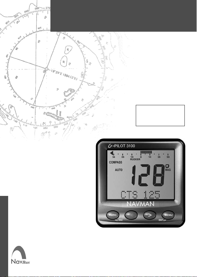
G-PILOT 3100
AUTOPILOT
Installation Manual
English..............3
Español...........32
Português.......61
www.navman.com
NAV MAN
Page 2

.
Page 3

Contents
Important................................................................................................4
1 In tro duc tion.........................................................................................5
1-1 A typical in stal la tion....................................................................................5
1-2 Using the G-PILOT 3100 with other in stru ments..........................6
1-2-1 Using other instruments..........................................................................6
1-2-2 NavBus ...................................................................................................6
1-2-3 NMEA......................................................................................................6
2 G-PILOT 3100 hardware.....................................................................7
2-1 What comes with your G-PILOT 3100 .......................................................7
2-2 Other parts required...................................................................................8
3 Installation...........................................................................................8
3-1 Installation sequence .................................................................................8
3-2 Installation guide........................................................................................9
3-2-1 Location guide.....................................................................................9
3-2-2 Wiring guide........................................................................................9
3-3 Installing the main unit .............................................................................10
3-4 Installing the power supplies and steer ing drive ...................................... 11
3-4-1 Installing the power supplies.............................................................11
3-4-2 Installing the steering drive ...............................................................12
3-5 Installing the rudder feedback unit...........................................................16
3-6 Installing the compass..............................................................................19
3-7 Installing the gyro.....................................................................................21
3-8 Installing the display unit and other instruments......................................23
4 Dockside setup.................................................................................25
4-1 Start dockside setup.................................................................................25
4-2 Calibrating the rudder feedback unit........................................................26
5 Sea trials ...........................................................................................27
5-1 Calibrating the compass...........................................................................27
6 Aligning the compass and the rudder............................................28
6-1 Aligning the compass...............................................................................28
6-2 Aligning the rudder...................................................................................28
Appendix A - Specifi cations...............................................................29
Appendix B - Alarm and warning messages.....................................29
Appendix C - Troubleshooting...........................................................31
Appendix D - How to contact us ........................................................90
G-PILOT 3100 Installation Manual
NAVMAN
3
Page 4

Important
It is the owner’s sole responsibility to install and use the instrument and transducer/s in a manner
that will not cause accidents, personal injury or property damage. The user of this product is
solely responsible for observing safe boating practices.
The choice, location, and installation of all components in any autopilot system is critical. If
installation is not correct, the unit can not perform at its designed potential. If in doubt, consult
your Navman dealer. Ensure that any holes that cut are in a safe position and will not weaken
the boat's structure. If in doubt, consult a qualifi ed boat builder.
Using the G-PILOT 3100:
The G-PILOT 3100 is intended as an aid to save a helmsman from having to steer for long
periods of time, not as the main means of steering the boat.
The G-PILOT 3100 is not intended for use in extreme weather, in adverse conditions or in
water near other boats, dangerous waters or land.
The G-PILOT 3100 can not control the boat better than a helmsman. In adverse conditions
steer the boat manually.
Never leave the helm unattended. Keep a watch at all times. The helmsman should always
monitor the course of the boat and the G-PILOT 3100 and be ready to resume steering the
boat manually.
The performance of the G-PILOT 3100 can be affected by the failure of a part,
environmental conditions, improper installation and use.
NAVMAN NZ LIMITED DISCLAIMS ALL LIABILITY FOR ANY USE OF THIS PRODUCT IN A
WAY THAT MAY CAUSE ACCIDENTS, DAMAGE OR THAT MAY VIOLATE THE LAW.
As Navman is continuously improving this product we retain the right to make changes to the
product at any time which may not be refl ected in this version of manual. Please contact your
nearest Navman offi ce if you require any further assistance.
Governing Language: This statement, any instruction manuals, user guides and other information
relating to the product (Documentation) may be translated to, or has been translated from,
another language (Translation). In the event of any confl ict between any Translation of the
Documentation, the English language version of the Documentation will be the offi cial version
of the Documentation.
Copyright © 2003 Navman NZ Limited, New Zealand. All rights reserved. Navman is a registered
trademark of Navman NZ Limited.
FCC Statement
Note: This equipment has been tested and found to comply with the limits for a Class B
digital device, pursuant to Part 15 of the FCC Rules. These limits are designed to provide
reasonable protection against harmful interference in a normal installation. This equipment
generates, uses and can radiate radio frequency energy and, if not installed and used in
accordance with the instructions, may cause harmful interference to radio communications. However, there is no guarantee that interference will not occur in a particular installation. If this equipment does cause harmful interference to radio or television reception,
which can be determined by turning the equipment off and on, the user is encouraged to
try to correct the interference by one or more of the following measures:
Reorient or relocate the receiving antenna.
Increase the separation between the equipment and receiver.
Connect the equipment into an output on a circuit different from that to which the
receiver is connected.
Consult the dealer or an experienced technician for help.
A shielded cable must be used when connecting a peripheral to the serial ports.
4
NAVMAN
G-PILOT 3100 Installation Manual
Page 5
1 Introduction
Using this manual
This manual describes how to install and set
up the G-PILOT 3100. Refer to the separate
G-PILOT 3100 Operation Manual for information on how to use the G-PILOT 3100.
To install a G-PILOT 3100, you must perform
installation, dockside setup and sea trials (see
sections 3, 4 and 5).
T o fully set up a G-PILOT 3100 after a part has
been changed or if a problem is suspected,
perform dockside setup and sea trials (see
sections 4 and 5).
To verify that the G-PILOT 3100 is operating
correctly, perform sea trials (see section 5).
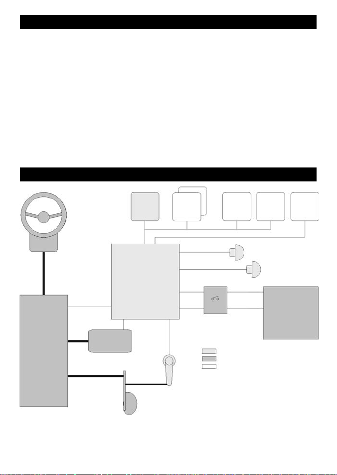
1-1 A typical installation
Display
unit
Manual helm
NavBus
Main
unit
Cleaning and maintenance
Clean the parts of the G-PILOT 3100 with a
damp cloth or mild detergent. Avoid abrasive
cleaners, petrol or other solvents.
Do not paint any part of the G-PILOT 3100
except for the cables.
Optional instruments
More
display
units
NMEA
WIND
3100
SPEED
3100
Compass
Gyro
GPS
NMEA
Light duty
Clutch drive
(optional)
Rudder control
G-PILOT 3100 Installation Manual
Steering
drive
Rudder
Rudder
feedback unit
NAVMAN
Power switch or switches
and power protection
Key
Parts supplied with G-PILOT
Other parts required
Optional parts
Note: Above shows typical
installation only. Please refer
to the information supplied with
your drive for further information.
Heavy duty
12 V DC
Power supply
5
Page 6

1-2 Using the G-PILOT 3100 with other instruments
1-2-1 Using other instruments
The G-PILOT 3100 can use data from these
instruments:
GPS: A GPS or chartplotter, such as a
Navman TRACKER 5000 series chartplotter
must be connected to the G-PILOT 3100 for
the G-PILOT 3100 to operate in GPS mode
(see the G-PILOT 3100 Operation Manual).
Note: GPS must be via NMEA input.
WIND: A wind instrument, such as a Navman
WIND 3100 series, must be connected to
the G-PILOT 3100 for the G-PILOT 3100 to
operate in WIND mode (see the G-PILOT
3100 Operation Manual).
SPEED: A speed instrument, such as:
Navman’s SPEED 3100 with a
paddlewheel speed sensor
or a GPS or chartplotter, such as
Navman’s TRACKER 5000 series
chartplotter can be connected to the
G-PILOT 3100 to increase steering
accuracy.
Note: The speed from a paddlewheel
sensor is the speed that the boat is moving
through the water. The speed from a GPS
is the speed over the ground. If there is a
water current then these two speeds will be
different. If the G-PILOT 3100 is connected
to an instrument with a paddlewheel sensor
and to a GPS, then the G-PILOT 3100 will
automatically use the speed from the
paddlewheel sensor instrument.
1-2-2 NavBus
NavBus is a Navman proprietary system that
allows systems of multiple instruments to be
built using a single set of transducers. When
instruments are connected by NavBus:
If you change the units, alarms or
calibration in one instrument, then the
values will automatically change in all
other instruments of the same type.
Each instrument can be assigned to a
group of instruments, called a backlight
group (see BKL GROUP in the FACTORY
menu, in the G-PILOT 3100 Operation
Manual). If you change the backlight in an
instrument in group 1, 2, 3 or 4 then the
backlight will automatically change in the
other instruments in the same group. If
6
NAVMAN
you change the backlight in an instrument
in group 0 then no other instruments are
affected.
If an alarm sounds, mute it on any
instrument which can display that alarm.
For more information, refer to the NavBus
Installation and Operation Manual. Note: GPS
must be via NMEA input.
NavBus and the G-PILOT 3100
The G-PILOT 3100 will automatically
work with additional display units.
The G-PILOT 3100 can receive wind data
from Navman’s WIND 3100 over NavBus.
The G-PILOT 3100 can receive speed
data from Navman’s SPEED 3100 over
NavBus.
1-2-3 NMEA
NMEA is an industry standard, but is not as
fl exible as NavBus as it requires dedicated
connections between instruments. The GPILOT has one NMEA input port and one
port that can be configured to be an input
or an output (See G-PILOT 3100 Operation
Manual).
G-PILOT 3100 NMEA inputs
GPS: The G-PILOT 3100 can receive
NMEA GPS data from a compatible GPS or
chartplotter, such as Navman’s TRACKER 5000
series chartplotter:
XTE (from APA, APB or XTE sentences)
is required for the G-PILOT to use GPS
mode
BRG (from APA sentences) and BOD
(from APA or APB sentences) are optional
and improve performance
COG (from VTG sentences) is optional
and can be displayed.
WIND: The G-PILOT 3100 can receive NMEA
wind data from a compatible wind instrument:
True or apparent wind direction (from
MWV sentences) is required for the
G-PILOT to use Wind mode.
SPEED: The G-PILOT 3100 can receive NMEA
speed data from a compatible paddlewheel or
GPS instrument:
SOG (from VTG sentences) is optional
and improves performance.
Note: If the G-PILOT 3100 is connected to a
G-PILOT 3100 Installation Manual
Page 7
Navman 3100 series wind or speed instrument
using NavBus, then the G-PILOT 3100 will
automatically receive and use the wind or
speed data, and the NMEA connection need
not be wired.
(see NMEA 2 DA T in the F ACTOR Y menu, See
G-PILOT 3100 Operation Manual).
G-PILOT 3100 NMEA outputs
The NMEA 2 port can be confi gured to be an
input or to be output:
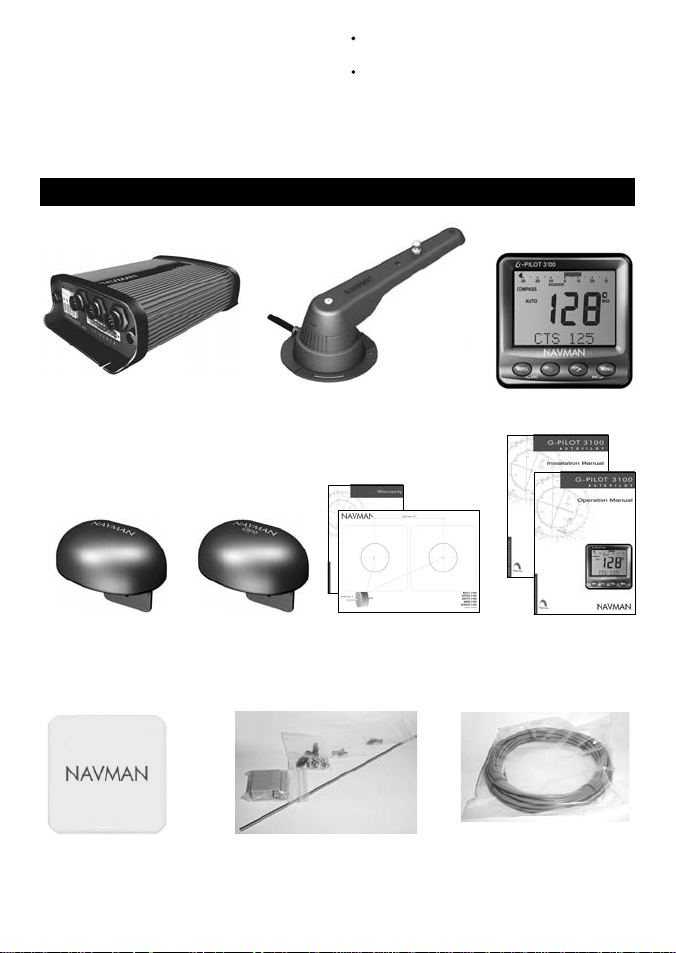
2 G-PILOT 3100 hardware
2-1 What comes with your G-PILOT 3100
either heading (HDG & HDT) and rudder
angle (RSA) once per second
or heading (HDG) ten times per second
Main unit
Compass, with 10
m (33 ft) attached
cable
Protective cover for
display unit
G-PILOT 3100 Installation Manual
Rudder feedback unit
Gyro, with 10 m
(33 ft) attached
cable
Mounting hardware, cable cover,
strain relief, spare fuses
Warranty and dis-
play unit mounting
NAVMAN
template
Display unit
This Installation
manual,
Operation manual.
2 mm (#14) twin stranded
cable for high current wiring
7
Page 8

2-2 Other parts required
Power supply: The G-PILOT 3100 requires
two power supplies, both nominally 12 V DC:
A heavy duty supply for the steering drive
A light duty supply for the G-PILOT 3100
electronics and display unit; this supply
also powers any additional display units
and other instruments.
The power supplies require one or two
switches and fuses or circuit breakers (see
section 3-4).
Steering drive: The G-PILOT 3100 can power
a hydraulic pump, constantly running pump set,
hydraulic linear drive or mechanical drive rated
at 12 V DC and up to 20 A.
Rudder linkage: To link rudder to rudder
feedback unit (see section 3-5).
For wiring, see Select Wire Table in section
3-4-2.
3 Installation
Warning Correct installation is critical to the
performance of the unit. It is vital to read this
manual and the documentation that comes with
the other parts before starting installation.
Warning
The G-PILOT main unit is not waterproof.
Mount the unit in a dry place.
The G-PILOT display unit is waterproof
from the front. Protect the rear of the unit
3-1 Installation sequence
The recommended installation sequence is:
1 Read this manual and the documentation
that comes with the other parts.
2 Plan the installation: select where the
equipment and wiring will be installed
(see section 3-2).
3 Install the main unit (see section 3-3).
4 Install the steering drive and wire the heavy
duty and light duty power supplies (see
section 3-4).
5 Install the rudder feedback unit (see
section 3-5).
6 Install the compass (see section 3-6).
External beepers or lights (optional ): The
external output is switched to ground, 30 V DC
and 250 mA maximum. If the beepers and lights
require more than 250 mA total, fi t a relay.
Other marine instruments (optional): Wind,
speed or GPS instruments can be connected
(see section 1-2).
Other parts: For systems of several
instruments, wiring and connectors are
required. Navman junction boxes can simplify
wiring several Navman instruments together
(see section 1-2 or the NavBus Installation
and Operation Manual).
Coupling connectors and 10 m (33 ft)
extension cables are available to extend the
rudder feedback unit, compass or gyro cables.
Do not fi t more than one extension cable to
each unit.
from water, or else water might enter the
breathing hole and damage the unit. The
warranty does not cover damage caused
by moisture or water entering the back of
the unit.
The compass, gyro and rudder feedback
unit are completely waterproof.
Warning Ensure that any holes that you cut
will not weaken the boat’s structure. If in doubt,
consult a qualifi ed boat builder.
7 Install the gyro (see section 3-7).
8 Install the display unit and any other
marine instruments that will be used with
the G-PILOT 3100 (see section 3-8).
9 Carry out the dockside setup (see
section 4).
10 Carry out the sea trials (see section 5).
If you are unsure where a part should be
installed, mount and wire the part temporarily,
without cutting holes in the boat. After the sea
trials have been completed, install and wire
the part permanently.
8
NAVMAN
G-PILOT 3100 Installation Manual
Page 9

3-2 Installation guide
This is a general guide for locating and wiring the parts of the G-PILOT 3100. The instructions for
a particular part may have additional requirements.
3-2-1 Location guide
Do not mount any part where it can be used
as a handhold, where it will interfere with
the operation of the boat or where it might
be submerged.
Do not mount any part where it will interfere
with launching or retrieving the boat.
Do not mount any part within 0.5 m (20")
of the plane of a radar antenna.
Mount the compass and gyro:
At least 1 m (3 ft) away from sources
of electrical signals or noise, such as
the batteries, high-current cables,
other boat cables, engines, fl uorescent
lights, power inverters, radio or radar
transmitters and antennas.
At least 1 m (3 ft) away from equipment
containing a magnet, such as a
compass.
3-2-2 Wiring guide
The G-PILOT 3100 has two kinds of cables:
The heavy-duty power supply and steering
drive usually require high-current cables:
Select the wire gauge from the wire size
table (see section 3-4-2).
Fit high-current cables at least 1 m (3
ft) away from other electronic devices in
the boat.
Keep the cables as short as possible.
Twin 2 mm (#14) cable is supplied with the
G-PILOT 3100 and can be used for the high
current cable if its gauge is suitable.
All the other cables are low-current:
Fit low-current cables at least 1 m (3 ft)
away from sources of electrical signals
or noise, such as the high-current cables,
other boat cables, engines, fluorescent
lights, power inverters and radio or radar
transmitters and antennas.
If the cable for the rudder feedback unit,
compass or gyro is too long, do not shorten
the cable; instead coil the cable up near the
main control unit.
The cable for the rudder feedback unit,
compass or gyro can be extended by
adding a 10 m (33 ft) extension cable and
coupling connector. Do not fi t more than
one extension cable to each unit.
When fi tting any type of cable:
Do not crush, pinch or strain the cable.
Secure the cable at regular intervals.
Ensure no connectors or exposed terminals
are in the bilge.
G-PILOT 3100 Installation Manual
NAVMAN
9
Page 10
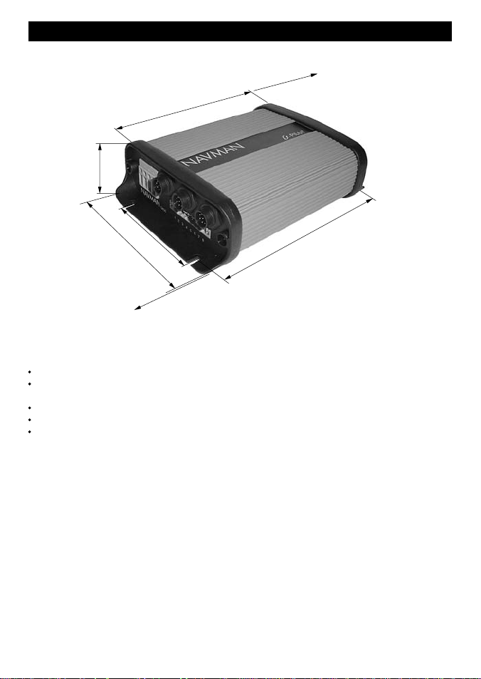
3-3 Installing the main unit
Physical
200 mm (7.87")
IMPORTANT: 200 mm (7.87")
clearance required for cover
removal
(2.16")
55 mm
Screws 90 mm (3.54") apart
200 mm (7.87")
140 mm (5.10")
Screw holes 184 mm (7.24") apart
IMPORTANT: 60 mm (2.36")
60 mm (2.36")
clearance required for cables
Installation
Find a suitable location for the unit:
In a dry, cool place; if possible not the engine room.
Close to the high-current power supply and the steering drive, to reduce the length of the
high current wiring.
Accessible for installation and service.
If possible on a vertical panel which does not vibrate.
Follow the location guide (see section 3-2-1).
Mount the unit with the cable connectors at the bottom or to one side, using the screws provided.
Do not mount the unit with the connectors at the top, because dust or moisture might enter
the unit.
10
NAVMAN
G-PILOT 3100 Installation Manual
Page 11
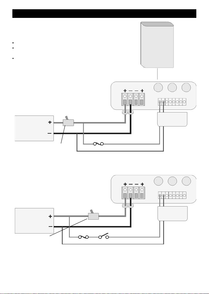
3-4 Installing the power supplies and steering drive
3-4-1 Installing the power supplies
The G-PILOT 3100 requires a light and a heavy duty
power supply, both 12 V DC (10.5 to 16.5 V DC).
Note:
Keep all wiring as short as possible.
For the heavy duty supply, use the wire size
given in the table (see section 3-4-2).
Follow the wiring guide (see section 3-2-2).
Power supply: one switch confi guration
Choose this confi guration to have one switch to turn the
G-PILOT 3100 and any other instruments on and off.
Main unit
1 2 3 4 5 6 7 8
Fit strain relief
12 V DC power
supply, current to
suit drive
Circuit breaker or fuse
and switch, current rating
to suit steering drive
Power supply: two switch confi guration
Choose this confi guration to be able to turn the
drive power off and leave other instruments
powered.
12 V DC power
supply, current to
suit drive
Circuit breaker or
fuse and switch,
current rating to
suit steering drive
Note: If powering more than three extra display units or other 3100 series instruments, fi t
another switch and fuse for the light duty power supply for these extra instruments
G-PILOT 3100 Installation Manual
Fuse 1 A
Fuse 1 A
Fit strain relief
Switch
NAVMAN
Heavy
duty
Heavy
duty power
Connector
cover
Light duty
power
1 2 3 4 5 6 7 8
Connector
cover
Light duty
power
11
Page 12

3-4-2 Installing the steering drive
Install the steering drive according to one of the
diagrams on the following pages.
Note
Keep all wiring as short as possible.
Use the wire size given in the table below.
Follow the wiring guide (see section
3-2-2).
Wire less than #10 gauge will not fi t
directly into the four way terminal block.
Fit ferrules or reterminate the wire with
#10 gauge wire.
If more than one wire is to be fi tted to a
terminal of the four way terminal block,
join the wires together in a suitable way.
Wire size table
To choose a wire gauge for an installation:
1 Measure the length of twin cable required, i.e. the distance from the main control unit to the
heavy duty power supply or to the drive.
2 Choose the column with the cable length and the row with the circuit current. The intersection
of the row and column gives the preferred (minimum) cable wire gauge for less than 3% voltage
drop in a 12 V system.
Cable length (from main control unit to power supply or to drive)
0.7 m 1.5 m 2.2 m 3 m 3.7 m 4.5 m 5.2 m 6 m
Current 2.5 ft 5 ft 7.5 ft 10 ft 12.5 ft 15 ft 17.5 ft 20 ft
1 amp #18 #18 #18 #18 #18 #18 #18 #18
2 amp #18 #18 #18 #18 #18 #16 #16 #16
3 amp #18 #18 #18 #16 #16 #16 #14 #14
4 amp #18 #18 #16 #16 #14 #14 #14 #12
5 amp #18 #18 #16 #14 #14 #12 #12 #12
6 amp #18 #16 #16 #14 #12 #12 #12 #10
7 amp #18 #16 #14 #14 #12 #12 #10 #10
8 amp #18 #16 #14 #12 #12 #10 #10 #10
9 amp #18 #16 #14 #12 #12 #10 #10 #10
10 amp #18 #14 #12 #12 #10 #10 #10 #8
15 amp #16 #12 #12 #10 #10 #8 #8 #6
20 amp #14 #12 #10 #8 #8 #6 #6 #6
12
NAVMAN
G-PILOT 3100 Installation Manual
Page 13

Example of hydraulic steering with hydraulic help pump.
In the VESSEL menu (See G-PILOT 3100 Operation Manual), set DRVE TYPE to MTR.
Main unit
1 2 3 4 5 6 7 8
Fit strain relief
Heavy duty power
No connection
(see section 3-4-1)
Wiring polarity
does not matter.
Motor
Example of mechanical steered power vessels with hydraulic linear drive for sailing boat
In the VESSEL menu (See G-PILOT 3100 Operation Manual), set DRVE TYPE to MTR.
Main unit
Note: Clutch relay coil must
draw less than 300 mA
(see section 3-4-1)
G-PILOT 3100 Installation Manual
Heavy duty power
Motor
Clutch
relay
coil
Fit strain relief
Wiring polarity
does not matter.
1N4002 diode or equivalent
Fit close to relay coil
NAVMAN
Connector
cover
13
Page 14

Installing a electric drive motor with clutch relay
In the VESSEL menu (See G-PILOT 3100
Operation Manual), set DRVE TYPE to MTR.
Main unit
1 2 3 4 5 6 7 8
Fit strain relief
Heavy duty power (see section 3-4-1)
1N4002 diode or equivalent
Fit close to relay coil
Relay contacts
Clutch
coil
Wiring polarity
does not matter.
Motor
1N4002 diode or equivalent. Fit close to relay coil
Note: Relay is required if the
clutch circuit is greater than 300 mA.
Installing a continuous running pump and solenoid valves.
In the VESSEL menu (See G-PILOT 3100
Operation Manual), set DRVE TYPE to SPL -.
Fit strain relief
Heavy duty power (see section 3-4-1)
Relay contacts
Note: Motor is not
required for engine
PTO systems.
Motor
Wiring polarity
does not matter.
Starboard
Port
14
NAVMAN
Main unit
1N4002 diode or equivalent
Fit close to relay coil
Note: Relay is required
if the clutch circuit is
greater than 300 mA.
Connector
cover
Relay coil
1 2 3 4 5 6 7 8
Connector
cover
Relay coil
G-PILOT 3100 Installation Manual
Page 15

Installing solenoid valves or relays with jog or electric steering
In the VESSEL menu (See G-PILOT 3100 Operation Manual), set DRVE TYPE to SPL -.
Main unit
1 2 3 4 5 6 7 8
Fit strain relief
Heavy duty power
(see section 3-4-1)
No connection
Starboard
Port
Jog/steer controls
G-PILOT 3100 Installation Manual
NAVMAN
15
Page 16

3-5 Installing the rudder feedback unit
Physical
Rudder
90 mm
(3.5")
220 mm
(8.7")
Linkage
to rudder
shaft
Connecting rod, with
quick release fi ttings
and lock nuts each end
Base
LT8 connector
10 m (33 ft) cable
Arm rotates freely
Arm
around base.
End of connecting
rod snaps into one of
the holes on the arm.
Mounting requirements
These two
distances to
be equal.
Adjust position of rod on
arm if required.
Base to be adjacent
to rudder shaft so that
this angle is 90°
Cut connecting
rod if required.
Note
The unit is completely waterproof but should not be immersed.
Mount the unit on a panel which does not vibrate.
Follow the location guide (see section 3-2-1).
16
NAVMAN
Thread = M5
These two
distances
to be equal.
Rudder shaft to
be parallel to
shaft in base.
Rudder linkage
and arm to move
in the same
plane
G-PILOT 3100 Installation Manual
Page 17

Alignment
The arm can rotate freely around the base. When the rudder is amidships, the arrow on the arm
must point to one of the centre lines on the base.
Centre line
Base
Centre line
Therefore in an installation, the base can be rotated to two positions. We recommend the position
that has the cable on the opposite side to the connecting rod.
Sets of lines
show the two
linear ranges of
the unit.
Recommended
(rudder amidships).
Not recommended, cable
can foul rudder linkage.
Arrangements
Recommended: U-shaped arrangement with the arm parallel to the length of boat:
Bow of
boat
Satisfactory: U-shaped arrangement
with arm not parallel to length of boat,
for example:
Bow of
boat
G-PILOT 3100 Installation Manual
Not recommended: Z-shaped arrangement,
for example:
If rudder turns too far, the unit might not return to
the Z shape.
NAVMAN
17
Page 18

Installation
1 Find a suitable location and arrangement for the unit as described above.
2 Choose, assemble and fi t a suitable rudder linkage.
3 Fit the unit as shown below:
Set rudder
amidships.
If necessary,
mount base on
block to set height.
Rotate base so arrow on arm
points near centre line on
base. Fit two screws provided
loosely in middle of slots.
Rotate base so arrow on
arm points to centre line
on base. Fit third screw
provided, tighten all screws.
Ensure rudder
is amidships.
Join coupling to
rudder linkage.
If necessary, cut connecting
rod at this end, then replace
Snap end into
correct hole in
arm.
coupling and lock nut.
4 Wire the cable back to the main unit, following the wiring guide (see section 3-2-2).
Holes in the bulkheads
Main unit
must be at least 18.5 mm
(0.73") diameter.
Plug connector into socket
18
NAVMAN
G-PILOT 3100 Installation Manual
Page 19

3-6 Installing the compass
Physical
Mounting holes
for screws
101 mm, (4")
71 mm, (2.8")
97 mm,
(3.8")
LT8 connector
Location
Mount the compass:
At least 1 m (3 ft) away from any steel or
iron boat part, such as:
a steel hull, deck, cabin or steel
reinforcing in ferro-cement hulls
steel equipment such as motors and
cooking equipment
places where steel objects are stored,
such as the anchor locker and storage
lockers
At least 2 m (6 ft) away from equipment
with a magnet and equipment which
generates electromagnetic fi elds, such as
a compass, a battery, high current wiring,
Fibreglass or wood hull and cabin: mount compass at the centre of movement (for planing hulls,
the centre of movement is usually close to the stern):
Steel hull, non-steel cabin: mount compass
1 m, (3 ft) above hull:
1 m (3 ft)
10 m (32.8 ft)
an electric motor and a radio or radar
transmitter or antenna.
As close as possible to the centre of
movement of the boat, to minimise how
much the compass moves when the boat
rocks and pitches. If the compass can not
be mounted at the centre of movement, it
is usually best to mount the compass as
low as possible.
On a vertical panel which does not
vibrate.
The unit is completely waterproof but should
not be immersed. The compass is not
affected by other metals, such as stainless
steel, copper or brass. Follow the location
guide (see section 3-2-1).
Steel hull and steel cabin: mount compass
on a pole 1 m (3 ft) above the hull and at
least 1 m (3 ft) from the cabin:
At least 1 m (3 ft)
1 m (3 ft)
G-PILOT 3100 Installation Manual
NAVMAN
19
Page 20

Installation
1 Find a suitable location for the unit as described above.
2 Mount the unit with the three screws provided. Use a level to ensure the unit is vertical to
within 10°.
Less than
10° 10°
Less than
10° 10°
3 Wire the cable back to the main unit, following the wiring guide (see section 3-2-2).
Main unit
Holes in the bulkheads must be at least
18.5 mm (0.73 in)
diameter.
Plug connector into socket
Note
If you move the compass with respect to the gyro while the power is on, wait for the heading
to stabilize.
20
NAVMAN
G-PILOT 3100 Installation Manual
Page 21

3-7 Installing the gyro
Physical
Mounting holes
for screws
101 mm, (4")
71 mm, (2.8")
97 mm,
(3.8")
LT8 connector
10 m (32.8 ft)
Location
Mount the gyro as close as possible to the cen tre of movement of the boat, to minimize how much
the gyro moves when the boat rocks and pitches.
Mount the gyro on a panel which does not vi brate.
The unit is completely waterproof but should not be immersed. Follow the location guide (see
sec tion 3-2-1).
The Ideal location is at the centre of movement (for planing hulls, the centre of movement is
usually close to the stern).
G-PILOT 3100 Installation Manual
NAVMAN
21
Page 22

Installation
1 Find a suitable location for the unit as described above.
2 Mount the unit with the three screws provided. Use a level to ensure the unit is vertical to
within 10°.
Less than
10° 10°
3 Wire the cable back to the main unit, following the wiring guide (see section 3-2-2).
Less than
10° 10°
Holes in the bulkheads
Main unit
must be at least 18.5 mm
(0.73") diameter.
Plug connector into socket
Note
If you move the gyro with respect to the compass while the power is on, wait for the heading
to stabilise.
22
NAVMAN
G-PILOT 3100 Installation Manual
Page 23

3-8 Installing the display unit and other instruments
Installing the display unit
1 Choose a location for the display unit that is:
Easily seen and close to the manual
helm.
Accessible from behind; the minimum
clearance required at the back is
50 mm (2") (see mounting diagram).
With the back of the unit protected
from moisture.
Follow the location guide (see section 3-2-1).
2 The unit must mount on a fl at panel which
is less than 20 mm (0.75") thick. Stick the
mounting template in place. Drill a 50 mm
(2") fi xing hole through the centre hole in
the template. Note that the template allows
space around the unit for the protective
cover.
3 Remove the fi xing nut from the back of
the unit. Insert the stud at the back of the
unit through the mounting hole. Hand
tighten the fi xing nut.
Wiring the display unit
Display
unit
Main unit
Clutch relay out, 8
NMEA 2, 7
NMEA in 1, 6
NMEA common, 5
NavBus -, Blue 4
NavBus +, Orange 3
Ground, Black 2
12 V power +, Red 1
Note
Wire the display unit power wires (red and black wires) to the eight way connector terminals 1 and
2 to ensure the display unit and main control unit have the same light duty power supply.
Connector cover
8-way connector
Green
Side view of display unit mounting
20 mm (0.75")
maximum thickness
Fixing hole
50 mm (2")
Display unit
Clearance 50 mm (2") minimum
Follow the wiring guide (see
section 3-2-2).
Display unit cable, Requires 6 mm (1/4 in) hole
through bulkhead.
Yellow (isolate, do not cut)
White (isolate, do not cut)
Light duty power
(see section 3-4-1)
Optional external beepers and
lamps for the external alarm. If
the beepers and lights require
more than 250 mA, fi t an external
relay.
Fixing
nut
Cables
G-PILOT 3100 Installation Manual
NAVMAN
23
Page 24

Wiring other instruments
More G-PILOT
display units
Follow the wiring guide (see section 3-2-2).
Other 3100 series
instruments
A GPS, such as a
Navman TRACKER
5000 series chartplotter
Display
units
3100
units
GPS
Main unit
NMEA
in & out
Power,
NMEA in
Clutch, optional
Clutch relay out, 8
NMEA 2, 7
NMEA in 1, 6
NMEA common, 5
NavBus -, Blue 4
NavBus +, Orange 3
Ground, Black 2
Connector cover
(see section 3-4-2)
NMEA in/out
GPS NMEA out
GPS NMEA common
Light duty power
(see section 3-4-1)
12 V power +, Red 1
Green (from one
display unit only)
GreenGreen
Beepers and lights
(see previous page)
Note:
Refer to the instrument’s installation manual for more wiring information.
If adding more than three display units or other 3100 series instruments, fi t a separate light-duty
power supply for the extra instruments (see section 3-4 or the instrument’s installation manual)
The external alarm outputs (green wire) of Navman 3100 series instruments and 5000 series
chartplotters can be connected together to drive the external beepers and lights.
In systems with several other instruments, we recommend using NavBus junction boxes to
simplify wiring (see the NavBus Installation and Operation Manual).
24
NAVMAN
G-PILOT 3100 Installation Manual
Page 25

4 Dockside setup
Perform the dockside setup:
after installing a G-PILOT 3100 system (see section 3)
after a part has been changed or if a problem is suspected
After dockside setup, perform the sea trials (see section 5 ).
4-1 Start dockside setup
1 Turn the G-PILOT 3100 on (See G-PILOT
3100 Operation Manual). If the rudder
moves, immediately turn the power off (See
G-PILOT 3100 Operation Manual) and check
for incorrect wiring. Check that the display
unit shows AP3100 on the bottom line for a
couple of seconds, then the version number,
then displays the normal heading display.
If you try to enter AUTO and the rudder
feedback unit or compass have not yet
been calibrated, then the G-PILOT will
display CAL ERROR.
2 If the G-PILOT 3100 has been used before,
reset all user data to the factory defaults:
i Go to NVM RESET in the FACTORY
menu (See G-PILOT 3100 Operation
Manual).
ii Press > to turn the function on.
iii Press MENU to reset the data.
iv Hold AUTO to exit the menus.
3 Enter the user data listed in the User Data table
below (See G-PILOT 3100 Operation Manual
to fi nd what each data item means and how
to enter the data). Beside each item, write
the value of the user data that you enter.
4 After entering the data, hold AUTO to exit
the menus.
User Data table (to record installation setup data)
VESSEL menu
Item Data value
VSL TYPE . . . . . . . . . . . . . .
DRVE TYPE . . . . . . . . . . . . . .
WIND TYPE . . . . . . . . . . . . . .
HDG TYPE . . . . . . . . . . . . . .
MAG VAR . . . . . . . . . . . . . .
OPTIONS menu
Menu Data value
DODGE ANG . . . . . . . . . . . . . .
TACK ANG . . . . . . . . . . . . . .
GYBE ANGLE . . . . . . . . . . . . . .
TACK DELY . . . . . . . . . . . . . .
TURN RATE . . . . . . . . . . . . . .
ALARMS menu
Item Data value
CE ALARM . . . . . . . . . . . . . .
XTE ALARM . . . . . . . . . . . . . .
WPT AKN . . . . . . . . . . . . . .
WND ALARM . . . . . . . . . . . . . .
(SAIL only)
BAT ALARM . . . . . . . . . . . . . .
CUR ALARM . . . . . . . . . . . . . .
FACTORY menu
Item Data value
BKL GROUP . . . . . . . . . . . . . .
KEY BEEPS . . . . . . . . . . . . . .
NMEA2 DAT . . . . . . . . . . . . . .
WARNING
Until the rudder feedback unit is calibrated (see section 4-2), there is no rudder limit. The user
must ensure that rudder is not driven onto an endstop when using the jog command (see G-PILOT
3100 Operation Manual).
G-PILOT 3100 Installation Manual
NAVMAN
25
Page 26

4-2 Calibrating the rudder feedback unit
This procedure matches the rudder feedback unit to the rudder.
Note
To exit the calibration at any time, press ESC.
If you do not move the rudder as prompted or the rudder feedback unit is not working then
the G-PILOT can not fi nish the calibration. The G-PILOT will display CALB FAIL. Press ESC,
fi x the problem and repeat the calibration.
In normal operation, the G-PILOT will not turn the rudder closer than 3° to an endstop.
RFU CAL
Go to RFU CAL in the DEVICES menu
(See G-PILOT 3100 Operation
ENT
CENTRE
Turn the manual helm until
the rudder is amidships
ENT
MAX PORT
Turn the manual helm
to turn the rudder to the
endstop which makes the
boat turn to port
ENT
MAX STBD
Turn the manual helm to
turn the rudder to the endstop which makes the boat
turn to starboard
ENT
ANGLE 25
With rudder at its starboard endstop, measure the rudder angle
from amidships
(30° in this example).
Press < or > to set the displayed
angle to the measured rudder
angle (30° in this example).
ANGLE 30
ENT
26
30°
CENTRE
Turn the manual helm until
the rudder is amidships
ENT
STAND CLR
Stand clear of rudder and linkage,
remove anything that will foul rudder’s
travel between endstops. The G-PILOT
is about to turn the rudder.
ENT
TEST LIMS
The G-PILOT turns the rudder to one
endstop, to the other endstop, then
back to amidships.
Press ESC at any time to stop the rudder.
ENT
Displayed rudder angle.
PILOT
ACPT CAL
Turn the manual helm to turn the rudder from one
endstop to another, checking that the displayed
rudder angle looks correct (7° in this example).
To cancel the calibration, press ESC
ENT
CALB DONE
The rudder feedback unit is calibrated.
ENT
End of calibration.
NAVMAN
G-PILOT 3100 Installation Manual
7°
Page 27

5 Sea trials
Perform the sea trials:
After performing the dockside setup (see
section 4).
To check the operation of the G-PILOT 3100.
For the sea trials, sail in an open area where
there are no other craft or obstructions. The
sea should be calm, the wind speed as low as
possible and there should be no currents.
5-1 Calibrating the compass
Note
To exit the calibration at any time, press ESC.
If the boat is not turned as prompted or the compass is not working then calibration can not be completed,
the G-PILOT displays CALB FAIL. Press ESC, fi x the problem and repeat the calibration.
Local disturbances in magnetic fi eld may affect the compass. Calibration must be preformed away
from large metal structures such as marinas, large ships etc.; this is the responsibility of the user.
Ensure that both sources are referencing the same north (true or magnetic). If your magnetic
compass has not been calibrated then you can use another source for heading. If using vessel’s
compass then ensure that the deviation tables are applied to check the autopilot’s compass.
Turn G-PILOT 3100 on (See G-PILOT 3100
Operation Manual). Use the manual helm to
sail a straight course at a slow speed.
CSU CAL
Go to CSU CAL in the DEVICES menu
(See G-PILOT 3100 Operation Manual).
TURN BOAT
Use the manual
helm to make 2.5
turns, steady turn to
port or starboard.
Turns should be
smooth and con-
tinuous in one direction.
Each rotation should take approximately
1 to 2 minutes to perform. The G-PILOT
detects when the boat has performed 2.5
rotations and automatically goes to the
Use the manual helm to sail a straight
course and ensure the boat heading does
not change during this step.
< ALIGN >
Press < or > to set the displayed heading
to the actual heading (20° in this example).
For example,
actual heading
is 20° and displayed heading
is 23°.
< ALIGN >
ENT
ACPT CAL
This step aligns the compass. If the
G-PILOT is connected to a GPS then press
MENU twice to skip this step and accept
the calibration. Then align the compass to
the GPS (see section 6-1-2).
Use an accurate compass or external GPS
to fi nd the actual boat heading. If using an
external GPS, sail as fast as convenient to
ensure the heading is accurate.
G-PILOT 3100 Installation Manual
Turn the manual helm to several headings,
checking that the displayed heading is close
to the actual heading.
To cancel the calibration, press ESC.
ENT
CALB DONE
The compass is calibrated.
NAVMAN
ENT
End of calibration.
27
Page 28

6 Aligning the compass and the rudder
The compass or rudder can be aligned separately.
6-1 Aligning the compass
This aligns the G-PILOT 3100 compass to
display the correct heading.
6-1-1 Aligning the G-PILOT 3100 compass
to a reference compass
Use an accurate compass or external GPS
to fi nd the actual boat heading. If using an
external GPS, sail as fast as convenient to
ensure the heading is accurate.
Use the manual helm to sail a
straight course and ensure the
boat heading does not change
during this procedure.
Go to ALIGN HDG in the DEVICES
menu (See G-PILOT 3100 Operation Manual)
The compass can be aligned either to a reference compass or to a GPS connected to the
G-PILOT 3100. Ensure there is no cross-wind
or current.
6-1-2 Aligning the G-PILOT 3100 compass to
a GPS connected to the G-PILOT
Sail as fast as convenient to ensure the
heading is accurate.
Use the manual helm to sail a
straight course and ensure the boat
heading does not change during this
procedure.
Go to ALIGN GPS in the DEVICES
menu (See G-PILOT 3100 Operation Manual).
ALIGN HDG
ENT
For example,
actual heading
is 20° and
displayed
< ALIGN >
Press < or > to set the displayed heading
to the actual heading (20° in this example).
heading is 23°.
< ALIGN >
ALIGN GPS
ENT
The G-PILOT 3100
records the GPS
heading.
Turn the manual helm to several head-
ENT
ings, checking that the displayed heading
is close to the actual heading.
End of calibration.
6-2 Aligning the rudder
This sets the rudder setting to sail a straight course. Ensure there is no cross-wind or current.
Use the manual helm to sail a
straight course at a normal cruising speed.
CENTR RFU
Go to CENTR RFU in the DEVICES menu
(G-PILOT 3100 Operation Manual).
28
NAVMAN
The G-PILOT 3100 records the
ENT
rudder position and sets the rudder
angle to zero.
End of calibration.
G-PILOT 3100 Installation Manual
Page 29

Appendix A - Specifi cations
Electrical
Heavy duty power supply 10.5 to 16.5 V
DC, 20 A maximum
Light duty power supply 10.5 to 16.5 V DC:
Main unit: 80 mA.
Each display unit, 30 mA without
backlighting, 110 mA with full
backlighting.
Other optional instruments: refer to the
instrument’s operation manual.
Interfaces
NavBus connection to other Navman
instruments.
NMEA 0183 outputs: HDG, HDT, RSA;
inputs APA, APB, BOD, BWC, MWD,
MWV, RMA, RMB, RMC, VHW, VTG,
XTE
NMEA 0183 ports:
NMEA 1: Input
NMEA 2: Can be programmed to be an
input or output
Standards compliance
EMC compliance
USA (FCC): Part 15 Class B.
Europe (CE): EN50081-1, EN50082-1
New Zealand and Australia (C Tick):
Environment:
Compass, gyro, rudder feedback unit:
completely waterproof.
Display unit: IP66 from front when
correctly mounted.
Main unit: requires a cool, dry, clean
environment.
AS-NZS 3548.
Main unit terminal block connections:
Terminal Signal
1 Heavy duty power positive, 10.5 to
16.5 V DC, 20 A maximum
2 Heavy duty power negative
3 Steering drive negative output
4 Steering drive positive output
Main unit connector connections:
Terminal Signal
1 Light duty power positive, 10.5 to
16.5 V DC, 80 mA maximum
2 Light duty power supply common
3 NavBus +
4 NavBus 5 NMEA common
6 NMEA in 1
7 NMEA in 2
8 Steering clutch relay drive output,
switched ground to turn relay on,
30 V DC, 300 mA maximum
Display unit power/data cable wires:
Wire Signal
Red Power positive, 10.5 to 16.5 V DC,
30 mA without backlighting, 110
mA with full backlighting
Black Power negative
Orange NavBus +
Blue NavBus Yellow Factory use (isolate, do not cut)
White Factory use (isolate, do not cut)
Green External alarm, switched to
ground,
30 V DC and 250 mA max.
Appendix B - Alarm and warning messages
Alarm display Reason for message Recommended action by user Notes
BAT ALARM Battery voltage is less than the Check batteries a
minimum value set by the user Disengage G-PILOT if voltage too low
CAL ERROR
or compass unit is not calibrated (see sections 5-2 and 6-1)
CCH ERROR The clutch current is to high Check clutch connection a s
CE ALARM Course error has exceeded the Manually steer boat towards course a
maximum value set by the user
CSU ERROR Compass not sending data to Check compass is connected to a s
main unit main unit; Service compass
CUR ALARM The motor current exceeded the Check steering drive is not jammed a s
maximum value set by the user Increase the alarm value
G-PILOT 3100 Installation Manual
The G-PILOT rudder feedback unit
NAVMAN
Calibrate both the units a
29
Page 30

Alarm display Reason for message Recommended action by user Notes
DRV ERROR Rudder angle does not change Check drive power is turned on a s
when steering drive operates Check RFU is connected to rudder
Check fuses inside end of main
control unit
Check steering drive operation
GPS ERROR GPS has stopped sending data to Check GPS operation a c s
main unit Check GPS connection
GSU ERROR Gyro not sending data to main unit Check gyro is connected to a s
main unit; Service gyro
MCU ERROR Main unit not sending data to Check display unit is connected to a s
display unit main unit
Service main unit or display unit
NAV ERROR GPS is not navigating to a waypoint Start GPS navigating to a waypointm
when trying to engage G-PILOT or along a route
NEXT WPT? Boat has reached a waypoint Press any key to proceed to cancel alarm
(in GPS mode and WPT AKN is on) Then press ENT to start steering to the
next waypoint or press ESC to return to
STBY
NO DATA G-PILOT not receiving GPS data Check GPS operation m
when setting mode to GPS Check GPS connection
or G-PILOT not receiving wind instrument Check wind instrument operation m
data when setting mode to wind Check wind instrument connection
NVM ERROR Main unit memory has been corrupted Service main unit a s
PHA ERROR Rudder turns wrong way to rudder Check the rudder feedback unit a s
feedback unit Perform a rudder calibration
RFU ERROR Rudder feedback unit has stopped Check rudder feedback unit is a s
sending data to main unit connected to main unit
Service rudder feedback unit
ROUTE END Boat has reached the end of Press ESC to change to STBY or
a GPS route press ENT to change to compass
mode, sailing at current heading
TRK ERROR G-PILOT has changed to GPS mode Press ESC to return to STBY or press
but boat is too far off course ENT to have the G-PILOT steer the boat
to the correct course.
TAK ERROR In wind mode, attempt to tack in the Change angle to wind m
wrong way or boat will be in irons
WND ALARM The wind angle has changed by more Change SWA a
than the alarm value Change to Compass mode
WND ERROR Wind instrument has stopped Check wind instrument operation a c s
sending data to main unit Check wind instrument connection
XTE ALARM XTE has exceeded the maximum Manually steer boat towards course a
value set by the user
Notes a Alarm sounds the internal and external (optional) beepers; press any key to mute
alarm, then press ESC to cacel the alarm message
c The G-PILOT 3100 changes to Compass mode
m The G-PILOT 3100 mode does ot change
s The G-PILOT 3100 changes to STBY
30
NAVMAN
G-PILOT 3100 Installation Manual
Page 31

Appendix C - Troubleshooting
This troubleshooting guide assumes that you
have read and understood this manual.
It is possible in many cases to solve diffi culties
without having to send the unit back to the
manufacturer for repair. Please follow this
troubleshooting section before contacting the
nearest Navman dealer.
There are no user serviceable parts. Specialized
methods and testing equipment are required to
ensure that the unit is reassembled correctly.
Repairs to the unit must only be carried out by a
service centre approved by Navman NZ Limited.
Users who service the unit themselves will void
the warranty. More information can be found on
our Website: www.navman.com
1 Unit will not turn on:
a Fuse blown or circuit breaker tripped.
b Battery voltage is outside the range
10.5 to 16.5 V DC.
c Power/data cable damaged.
2 G-PILOT 3100 makes too frequent
course corrections:
The value of response is too low (see
G-PILOT 3100 Operation Manual).
3 When sailing a straight course, the boat
drifts from side to side of the course:
a The boat should drift from side to side
of the course when the G-PILOT 3100
steering is optimized.
b Change to a profi le suitable for
boat speed and sea conditions (see
G-PILOT 3100 Operation Manual).
c If the boat drifts too far from the
course, adjust response, ratio,
counter rudder gain, GPS gain (if
G-PILOT is in GPS mode) or wind
gain (if G-PILOT is in wind mode) (see
G-PILOT 3100 Operation Manual).
4 When sailing a straight course, the boat
drifts off course:
a Change to a profi le suitable for
boat speed and sea conditions (see
G-PILOT 3100 Operation Manual).
b Adjust response, ratio, counter rudder
gain, GPS gain (if G-PILOT is in GPS
mode) or wind gain (if G-PILOT is
in wind mode) (see G-PILOT 3100
Operation Manual).
G-PILOT 3100 Installation Manual
.
NAVMAN
5 When making a large course change,
boat does not follow the expected
course:
a Change to a profi le suitable for
boat speed and sea conditions (see
G-PILOT 3100 Operation Manual).
b Check turn rate is not too low (go
to TURN RATE in the OPTIONS
menu, see G-PILOT 3100 Operation
Manual).
c Adjust counter rudder gain (see
G-PILOT 3100 Operation Manual).
6 Boat turns too sharply:
Reduce turn rate (go to TURN RATE
in the OPTIONS menu, see G-PILOT
3100 Operation Manual).
7 The word SIMULATE flashes on
the display, values displayed are
unexpected:
Unit is in simulate mode (See
G-PILOT 3100 Operation Manual).
8 The display fogs:
a Moist air has entered the breathing
tube at the rear of the unit. Air the
boat or run unit with backlight fully on.
b Water has entered the breathing tube.
Return unit for service.
31
Page 32

Appendix D - How to contact us www.navman.com.
NORTH AMERICA
Navman USA Inc.
30 Sudbury Rd, Acton, MA 01720.
Toll Free: +1 866 628 6261
Fax: +1 978 897 8264
e-mail: sales@navmanusa.com
web:www.navman.com
AUSTRALIA
Navman Australia Pty. Limited
Unit 2 / 5-13 Parsons St.
Rozelle, NSW 2039, Australia.
Ph: +61 2 9818 8382
Fax: +61 2 9818 8386
e-mail: sales@navman.com.au
web: www.navman.com
OCEANIA
New Zealand
Absolute Marine Ltd.
Unit B, 138 Harris Road,
East Tamaki, Auckland.
Ph: +64 9 273 9273
Fax: +64 9 273 9099
e-mail: navman@absolutemarine.co.nz
Papua New Guinea
Lohberger Engineering,
Lawes Road, Konedobu.
PO Box 810, Port Moresby.
Ph: +675 321 2122
Fax: +675 321 2704
e-mail: loheng@online.net.pg
web: www.lohberger.com.pg
SOUTH AMERICA
Argentina
Costanera Uno S.A.
Av Pte Ramón S. Castillo y Calle 13
Zip 1425 Buenos Aires, Argentina.
Ph: +54 11 4312 4545
Fax +54 11 4312 5258
e-mail:
purchase@costanerauno.com.ar
web: www.costanerauno.ar
Brazil
Equinautic Com Imp Exp de Equip
Nauticos Ltda.
Rua Ernesto Paiva, 139
Clube dos Jangadeiros
Porto Alegre - RS - Brasil
CEP: 91900-200.
Ph: +55 51 3268 6675
+55 51 3269 2975
Fax: +55 51 3268 1034
e-mail:
equinautic@equinautic.com.br
web: www.equinautic.com.br
Realmarine
Estrada do Joa 3862,
Barra da Tijuca, Rio de Janeiro,
Brazil. CEP: 22611-020.
Ph: +55 21 2483 9700
Fax: +55 21 2495 6823
e-mail: tito@realmarine.com.br
web: www.realmarine.com.br
Chile
Equimar
Manuel Rodrigurez 27
Santiago, Chile.
Ph: +56 2 698 0055
Fax +56 2 698 3765
e-mail: mmontecinos@equimar.cl
Mera Vennik
Colon 1148, Talcahuano,
4262798, Chile.
Ph: +56 41 541 752
Fax +56 41 543 489
e-mail: meravennik@entel.chile.net
90
CENTRAL AMERICA
Mexico
Mercury Marine de Mexico
Anastacio Bustamente #76
Interior 6 Colonia Francisco Zarabia,
Zapapan, Jalisco, C.P. 45236 Mexico.
Ph: +52 33 3283 1030
Fax: +52 33 3283 1034
web: www.equinautic.com.br
ASIA
China
Peaceful Marine Electronics Co. Ltd.
Guangzhou, Hong Kong, Dalian,
Qingdao, Shanghai
1701 Yanjiang Building
195 Yan Jiang Zhong Rd. 510115
Guangzhou, China.
Ph: +86 20 3869 8839
Fax: +86 20 3869 8780
e-mail: sales@peaceful-marine.com
web: www.peaceful-marine.com
India
Access India Overseas Pvt. Ltd.
A-98, Sector 21,
Noida - 201 301, India.
Ph: +91 120 244 2697
TeleFax: +91 120 253 7881
Mobile: +91 98115 04557
e-mail: vkapil@del3.vsnl.net.in
Esmario Export Enterprises
Block No. F-1, 3rd Floor, Surya Towers
Sardar Patel Rd, Secunderbad 500 003.
Ph: +91 40 2784 5163
Fax: +91 40 2784 0595
e-mail: gjfeee@hd1.vsnl.net.in
web: www.esmario.com
Indonesia
Polytech Nusantara,
Graha Paramita 2nd Floor,
Jln Denpasar Raya Blok D2
Kav 8 Kuningan, Jakarta 12940.
Ph: +62 21 252 3249
Fax: +62 21 252 3250
e-mail: polytech@transavia.co.id
Korea
Kumhomarine Technology Co. Ltd.
#604-842, 2F, 1118-15, Janglim1-Dong,
Saha-Gu, Busan, Korea.
Ph: +82 51 293 8589
Fax: +82 51 265 8984
e-mail: info@kumhomarine.com
web: www.kumhomarine.com
Maldives
Maizan Electronics Pte. Ltd.
Henveyru, 08 Sosunmagu.
Male', Maldives.
Mobile: +960 78 24 44
Ph: +960 32 32 11
Fax: +960 32 57 07
e-mail: ahmed@maizan.com.mv
Singapore, Malaysia, Brunei,
Indonesia and Phillipines
RIQ PTE Ltd.
Blk 3007, 81 Ubi Road 1, #02-440,
Singapore 408701.
Ph: +65 6741 3723
Fax : +65 6741 3746
e-mail: riq@postone.com
Taiwan
Seafirst International Corporation
No. 281, Hou-An Road, Chien-Chen
Dist. Kaohsiung, Taiwan R.O.C.
Ph: +886 7 831 2688
Fax: +886 7 831 5001
e-mail: seafirst@seed.net.tw
web: www.seafirst.com.tw
NAVMAN
Thailand
Thong Electronics (Thailand) Co. Ltd.
923/588 Ta Prong Road, Mahachai,
Muang, Samutsakhon 74000, Thailand.
Ph: +66 34 411 919
Fax: +66 34 422 919
e-mail: sales@thongelectronics.com
admins@thongelectronics.com
web: www.thongelectronics.com
Vietnam
Haidang Co. Ltd.
1763 Le Hong Phong St. Ward 12
District 10, Ho Chi Minh City.
Ph: +84 8 863 2159
Fax: +84 8 863 2124
e-mail: sales@haidangvn.com
web: www.haidangvn.com
MIDDLE EAST
Lebanon and Syria
Balco Stores
Balco Building, Moutran Street,
Tripoli (via Beirut). - Lebanon
P.O. Box: 622.
Ph: +961 6 624 512
Fax: +961 6 628 211
e-mail: balco@cyberia.net.lb
United Arab Emirates
Kuwait, Oman, Iran, Saudi
Arabia, Bahrain & Qatar
Abdullah Moh’d Ibrahim Trading, opp
Creak Rd. Baniyas Road, Dubai.
Ph: +971 4 229 1195
Fax: +971 4 229 1198
e-mail: sales@amitdubai.com
AFRICA
South Africa
Pertec (Pty) Ltd (Coastal Division)
16 Paarden Eiland Road.
Paarden Eiland, 7405
PO Box 527,
Paarden Eiland, 7420
Cape Town, South Africa.
Ph: +27 21 508 4707
Fax: +27 21 508 4888
e-mail: info@kfa.co.za
web: www.pertec.co.za
EUROPE
France, Belgium and Switzerland
Plastimo SA
15, rue Ingénieur Verrière,
BP435,
56325 Lorient Cedex.
Ph: +33 2 97 87 36 36
Fax: +33 2 97 87 36 49
e-mail: plastimo@plastimo.fr
web: www.plastimo.fr
Germany
Navimo Deutschland
15, rue Ingénieur Verrière
BP435- 56325 Lorient Cedex.
Ph: +49 6105 92 10 09
+49 6105 92 10 10
+49 6105 92 10 12
Fax: +49 6105 92 10 11
e-mail:
plastimo.international@plastimo.fr
website: www.plastimo.de
Italy
Navimo Italia
Nuova Rade spa, Via del Pontasso 5
16015 Casella Scrivia (GE).
Ph: +39 1096 80162
Fax: +39 1096 80150
e-mail: info@nuovarade.com
web: www.plastimo.it
Holland
Navimo Holland
Industrieweg 4,
2871 JE Schoonhoven.
Ph: +31 182 320 522
Fax: +31 182 320 519
e-mail: info@plastimo.nl
web: www.plastimo.nl
United Kingdom
Navimo UK
Hamilton Business Park
Bailey Road, Hedge End
Southhampton, Hants S030 2HE.
Ph: +44 01489 778 850
Fax: +44 0870 751 1950
e-mail: sales@plastimo.co.uk
web: www.plastimo.co.uk
Sweden, Denmark, Finland and
Norway
Navimo Nordic
Lundenvägen 2,
473 21 Henån.
Ph: +46 304 360 60
Fax: +46 304 307 43
e-mail: info@plastimo.se
web: www.plastimo.se
Spain
Navimo España
Avenida Narcís Monturiol, 17
08339 Vilassar de Dalt,
Barcelona.
Ph: +34 93 750 75 04
Fax: +34 93 750 75 34
e-mail: plastimo@plastimo.es
web: www.plastimo.es
Portugal
Navimo Portugal
Avenida de India N°40
1300-299 Lisbon.
Ph: +351 21 362 04 57
Fax: +351 21 362 29 08
e-mail: plastimo@siroco-nautica.pt
web: www.plastimo.com
Other countries in Europe
Plastimo International
15, rue Ingénieur Verrière BP435
56325 Lorient Cedex, France.
Ph: +33 2 97 87 36 59
Fax: +33 2 97 87 36 29
e-mail:
plastimo.international@plastimo.fr
web: www.plastimo.com
REST OF WORLD/
MANUFACTURERS
Navman NZ Limited
13-17 Kawana St.
Northcote.
P.O. Box 68 155,
Newton,
Auckland,
New Zealand.
Ph: +64 9 481 0500
Fax: +64 9 481 0590
e-mail: marine.sales@navman.com
web: www.navman.com
G-PILOT 3100 manual de instalação
Page 33

.
Page 34

Made in New Zealand
MN000212E
G-PILOT 3100 Installation
Lon 174° 44.535'E
Lat 36° 48.404'S
NAVMAN
 Loading...