

Page 1

ABSYNTH 4
Operation Manual
Page 2

The information in this document is subject to change without notice and does not
represent a commitment on the part of NATIVE INSTRUMENTS Software Synthesis
GmbH. The software described by this document is subject to a License Agreement
and may not be copied to other media. No part of this publication may be copied,
reproduced or otherwise transmitted or recorded, for any purpose, without prior
written permission by NATIVE INSTRUMENTS Software Synthesis GmbH. All product
and company names are trademarks of their respective owners.
And also, if you’re reading this, it means you bought the software rather than stole
it. It’s because of people like you that we can continue to create great tools and
update them. So, thank you very much.
Users Guide written by Christoph Laue.
Special thanks to the Beta Test Team, who were invaluable not just in tracking down
bugs, but in making this a better product.
© NATIVE INSTRUMENTS GmbH, 2006. All rights reserved.
Germany USA
NATIVE INSTRUMENTS GmbH NATIVE INSTRUMENTS North America, Inc.
Schlesische Str. 28 5631 A Hollywood Boulevard
D-10997 Berlin Los Angeles, CA 90028
Germany USA
info@native-instruments.de info@native-instruments.com
www.native-instruments.de www.native-instruments.com
Page 3

Table Of Contents
1. Welcome to ABSYNTH 4! ................................................................ 7
2. Installing and Setting Up ABSYNTH 4 ............................................. 8
3. Overview ....................................................................................... 9
3.1. What’s new in ABSYNTH 4? ....................................................... 9
3.2. The Idea behind ABSYNTH 4 ...................................................10
3.2.1. Semi-Modular Design .....................................................10
3.2.2. Modulation ....................................................................11
3.2.3. Macro Controls ..............................................................11
3.2.4. Waveforms ....................................................................11
3.3. An Overview of the User Interface .............................................13
3.3.1. Navigation Bar ...............................................................13
3.3.2. Browser & Attributes Window .........................................13
3.3.3. Perform Window ............................................................15
3.3.4. Patch Window................................................................16
3.3.5. Effect Window ...............................................................17
3.3.6. Wave Window ................................................................18
3.3.7. Envelope Window ...........................................................18
3.3.8. LFO Window ................................................................. 20
3.4. Quick Intro ............................................................................21
3.4.1. Loading and Playing Sounds ...........................................21
3.4.2. Creating Own Sounds .....................................................24
3.4.3. Producing and Morphing Waveforms ................................ 30
4. Reference ................................................................................... 35
4.1. Interaction with Control Features .............................................. 35
4.1.1. Windows und Tabs ......................................................... 35
4.1.2. Module On/Off Switches ................................................ 36
4.1.3. Popup Menus ............................................................... 36
4.1.4. Value Fields ...................................................................37
4.1.5. Fader and Knobs ............................................................37
4.2. Stand-Alone Menu .................................................................. 38
4.2.1. Import GLO File… ......................................................... 38
4.2.2. Options ........................................................................ 38
4.2.1. Help Menu ....................................................................41
4.2.2. Audio and MIDI Setting ..................................................41
4.3. Navigation Bar ....................................................................... 42
4.3.1. Window Selection Area .................................................. 43
4.3.2. CPU Meter ................................................................... 43
4.3.1. Level Meter Displays ...................................................... 44
Absynth 4 – 3
Page 4

4 – Absynth 4
4.3.2. Panic Button ................................................................ 44
4.3.3. NI Logo ....................................................................... 44
4.4. Patch Window ........................................................................ 45
4.4.1. Signal ow ................................................................... 46
4.4.2. Oscillator Module .......................................................... 48
4.4.3. Filter Module ................................................................ 62
4.4.4. Modulation Module ....................................................... 67
4.4.5. Waveshape Module ....................................................... 68
4.5. Effect Window .........................................................................69
4.5.1. General Interaction .........................................................70
4.5.2. Pipe .............................................................................72
4.5.3. Multicomb .....................................................................74
4.5.4. Multitap ........................................................................76
4.5.5. Echoes ........................................................................ 77
4.5.6. Resonators ....................................................................79
4.6. Wave Window ........................................................................ 80
4.6.1. Waveform View, Spectrum View, Morph View .....................81
4.6.2. Creating new Waves .......................................................81
4.6.3. Editing Waves ............................................................... 82
4.6.4. Spectrum Edit .............................................................. 85
4.6.5. Wave Morph ................................................................. 86
4.7. Envelope window .................................................................... 89
4.7.1. Fundamentals for Operation ............................................ 89
4.7.2. Breakpoints, Transitions/Steps, Sync ................................91
4.7.3. Envelope Modes ............................................................ 94
4.7.4. Sample Jump ...............................................................101
4.7.5. Envelope LFO ...............................................................102
4.7.6. Envelope Modulation .....................................................103
4.7.7. Master Envelope ...........................................................105
4.7.8. Transform Commands ...................................................107
4.8. LFO Window .........................................................................109
4.8.1. Oscillator Section ......................................................... 111
4.8.2. Modulation Sections .....................................................112
4.9. Perform Window .................................................................... 115
4.9.1. Global Features ............................................................115
4.9.2. Automation in ABSYNTH 4: Macro Controls .................... 117
4.9.3. Controllers Page ...........................................................120
4.9.4. Assignments Page ........................................................122
4.9.5. MIDI Page ...................................................................123
4.9.6. Note Page ...................................................................125
Page 5

4.9.7. Tuning Page .................................................................126
4.9.8. Audio Mod ..................................................................128
4.10. The Browser and Attributes Windows .....................................130
4.10.1. The Attributes Concept and the KoreSound ...................130
4.10.2. Searching and Loading Sounds with the Browser ............131
4.10.3. Dening Attributes and Saving KoreSounds ...................138
Appendix A – How to Work with Attributes .........................................140
Appendix B – Attributes Reference ...................................................151
Index .............................................................................................164
Absynth 4 – 5
Page 6

6 – Absynth 4
Page 7

1. Welcome to ABSYNTH 4!
We are delighted that you have chosen ABSYNTH 4. You now own a synthesizer, which is capable of producing some of the most daring sounds.
Whether you are developing a lm soundtrack or “just want to make music”
– ABSYNTH 4 always has the right sound in store for you. The semi-modular
design allows you to combine oscillators, modulation sources, and lters in
any way you want. You can create unusual and dynamic sounds by combining
the numerous effects and modulation possibilities in different ways. The new
Marco Controls allow you to operate several parameters at the touch of a button, just pressing one key of your MIDI controller. Or you can take advantage
of the automation capabilities in your Audio MIDI Sequencer to trigger your
sounds into action.
With all these possibilities, the operational ease of ABSYNTH 4 never fails to
impress: you can nd the right sound quickly and intuitively using the sound
browser. Simply state the characteristics that the desired sound requires and
let ABSYNTH 4 perform the search. The newly designed interface now has
a clearer structure so that you can quickly nd important operating features
and always keep them in view. All this allows you to realize your musical ideas
and make great music without having to take detours. This is exactly what
you should set out to do right now!
The ABSYNTH 4 TEAM at NATIVE INSTRUMENTS
Wishes you the best of luck with ABSYNTH 4.
Absynth 4 – 7
Page 8

8 – Absynth 4
2. Installing and Setting Up ABSYNTH 4
We recommend that you rst follow the steps described in the Setup Guide
supplied separately before you start reading this manual. The Setup Guide
explains how to install ABSYNTH 4 on your computer, how to setup the audio
and MIDI interfaces of the Stand-Alone Version or alternatively, how to incorporate ABSYNTH 4 as a plug-in to your Audio MIDI Sequencer. The Setup Guide
also includes a step-by-step introduction to using the new NI Service Center,
which is available online to help you activate ABSYNTH 4 for permanent use
on your computer and search comfortably for new updates with ease.
Page 9

3. Overview
In this chapter you will nd a list of the new and modied functions in
ABSYNTH 4. You will learn about the concept behind ABSYNTH 4 and get to
know the interface. The practical examples will simplify the learning process,
to get you started with designing your own sounds.
3.1. What’s new in ABSYNTH 4?
Here you will nd a short overview of the new features in ABSYNTH 4 compared to ABSYNTH 3.
• Wave Morphing: this new waveform type allows you to fuse two wave-
forms into a new one.
• Sync Granular Mode: this new sound source in the oscillator module
produces organic sounds, that are reminiscent of blowing into or strumming a traditional instrument.
• Expanded Resonator effect: the new parameter Drive allows you greater
control over the input signal, which can be manipulated all the way to
distortion.
• Audio Mod: the level of an audio signal can now act as a modulation
source in order to use ABSYNTH as an effect. The level of an oscillator
can also be used to modulate an effect parameter.
• Macro Controls assemble all incoming and outgoing modulation and
automation data to allow you to quickly interact with the parametersparameters
of ABSYNTH, for example, in conjunction with a host sequencer or in example, in conjunction with a host sequencer or in
a live situation.
• Sound Browser lets you search for the sounds you require in a fast and
intuitive way, easing the administration of large sound collections and
allowing seamless integration into KORE of NATIVE INSTRUMENTS.
• Master ADSR: the new global operating envelope Master ADSR allows
fast and effective transformation of complex sounds.
• Step Mode in Envelopes: allow you to place break points in a rhythmEnvelopes: allow you to place break points in a rhythm: allow you to place break points in a rhythm
grid, similar to the principle of a step sequencer.
• A logical interface: clear structure and new operating features ensure
quick access to all Parameters.
Absynth 4 – 9
Page 10

10 – Absynth 4
3.2. The Idea behind ABSYNTH 4
We would now like to introduce you to several of your synthesizer’s fundamental
concepts so that you are familiar with how ABSYNTH 4 is constructed and
some of the advantages of its design. You will continuously encounter these
concepts in your work with ABSYNTH 4. It is worth reading this section even
if you are familiar with ABSYNTH from an earlier version. There are several
new things to discover!
3.2.1. Semi-Modular Design
The semi-modular design of ABSYNTH 4 allows you to adapt the structure of
your sound production to meet your own demands. Unlike in hardware synthesizers, you yourself can determine to a large extent the number and order
of the oscillators, lters and other features you wish to use: for example you
can have a lter follow a wave shaper and an oscillator in sequence or send
the signal through two lters one after the other.
ABSYNTH 4 offers three so-called Channels in the Patch Window, which
you can combine with Modules as deemed necessary. An Oscillator Module
always sits at the top of a Channel. The Oscillator Modules are the only sound
sources in ABSYNTH 4. They provide the foundation for every sound. One of
the three Oscillator Modules must always be active in order to hear a sound.
The other two Module positions in each Channel can be freely assigned to
one of the following three Modules:
The Modulation Module offers you access to the ring modulator (Ringmod)
and the Frequency Shifter. The Filter Module gives you fourteen different lter
types to choose from. They range from various high and low-pass lter types
to all-pass and notch lters. By using the Waveshape Module you can give
the input signal the character of any Waveform you want.
The signals of the three Channels A to C then run together through the Master
Channel. Here you can also activate up to three Modules. In the rst two
positions, you can insert a Filter Module or Modulation Module. In the third
position, you nd the Effect Module, which enables you to make unusual
delay and resonator effects.
To use the same settings for several modules, you simply copy the Modules
and insert them into free Module positions. You can also store frequently used
combinations in a library, as well as load complete Channel assemblies with
the push of a button. In chapter 3.3.4 you will nd an overview of individual
features in the Patch Window.
Read section 3.4.2 to learn out how to insert Modules into the Channels and
thus create the foundation for your own and individual sounds.
Page 11

3.2.2. Modulation
ABSYNTH is known for its lively, organic sounds that grow and change whilst
being played over time. The backgrounds of these capabilities are the exible
possibilities of modulation in ABSYNTH 4. To change a parameter for the duration of a sound, you simply connect a parameter with a modulation source.
The modulation source then takes control of the relevant parameter.
There are different modulation sources to choose from in ABSYNTH: you can
produce very good cyclical value sequences with an LFO, for example by let- by let-
ting the amplitude of an oscillator go up and down or by changing the cutoff
frequency of a lter.
To precisely modify the value of a parameter at a certain point in the sound,
you must connect the value changes with the specic break points of the
Envelopes. There are 64 break points to choose from as a trigger for value
changes.
You can nd a guide to the practical application of Envelopes in section 3.4.2,
whilst the LFO Window is introduced in section 3.3.8.
3.2.3. Macro Controls
Use the Macro Controls to control any parameter via MIDI hardware or by
using sequencer automation. You can then raise the lter resonance in real
time, or move the break points of the envelopes.
Macro Controls assemble all of the incoming and outgoing control data, which
you can then move into groups using the parameters in ABSYNTH. You can
easily assign any MIDI source to a Macro Control in the Perform Window using
MIDI Learn. From here, you can then control all the parameters in this group
using a rotary controller on your MIDI keyboard or an automation track from
your sequencer software.
You can learn how the Perform Window looks using the diagrams in section
3.3.7. A list of the control feature names is also included.
3.2.4. Waveforms
In ABSYNTH 4 you do not have to depend on pre-assembled waveforms such
as a sine or sawtooth curve: instead you can produce your own waveforms and
implement them as a sound source or controller for modulations.
In many areas of ABSYNTH 4, Waveforms play an important role, for example,
in the Oscillator Modules or in the LFO Window. Although a large number of
nished Waveforms are provided for immediate use, ABSYNTH 4 does not limit
you to these readymade waveforms when you make new sounds. Instead, you
Absynth 4 – 11
Page 12

12 – Absynth 4
may start from scratch and design your own waveforms in the Wave Window.
To do this you simply select one of the graphic tools and draw the curves with
the mouse. You can then apply different functions to the Waveform such as
turning the curve on its head or changing the phase. You can also produce
many weird and wonderful sounds using the Fractalize tool..
As well as randomly changing the curve progression (and thus the temporal
component) of an oscillation loaded as a Waveform, you can also edit the you can also edit the
(harmonic) fractal sounds using the tools in the bottom-view Spectrum. Just
draw the amplitude and phase of the harmonic sounds and you can produce
subtle to drastic changes in sound over the curve progression.
It is best to save the results and store them in your own Waveform library.
These waveforms are then readily available in ABSYNTH 4. You can either
use these waveforms individually or “morph” them with the function Morph.
This is how interesting curve progressions are produced, which allows greater
variety in the creation of your sounds. You can learn about the Wave Window
and its features in section 3.3.6. To learn more about creating, storing, and
morphing waveforms refer to section 3.4.3.
Page 13
3.3. An Overview of the User Interface
In the following pages we will introduce you to the individual Windows and
their features to help you understand the interface of ABSYNTH 4. You may
also use this as a reference guide in case you ever forget the name of a certain
switch or controller.
You will nd tips for handling the different user interfaces and further information about core features in section 4.1.
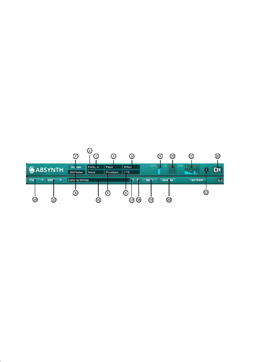
3.3.1. Navigation Bar
The Navigation Bar is a central feature in ABSYNTH 4 because it is the only
menu always present in the user interface. Here you can switch between
Windows with particular work environments. From here you can also access
the dialogs for loading and storing data through various Popup Menus. You are
over-seeing the vital functions of ABSYNTH 4 with the different status displays.
There is more on the Navigation Bar and its features in section 4.3.
(1) Perform Tab
(2) Patch Tab
(3) Effect Tab
(4) Wave Tab
(5) Envelope Tab
(6) LFO Tab
(7) Browser Tab
(8) Attributes
(9) CPU Meter
(10) Input Level Meter
(11) Output Level Meter
(12) Panic Button
(13) NATIVE INSTRUMENTS Logo
(14) File Popup Menu
(15) Edit Popup Menu
(16) Sound Name Display
(17) Previous Sound Button
(18) Next Sound Button
(19) Save Button
(20) Save As Button
Absynth 4 – 13
Page 14
14 – Absynth 4
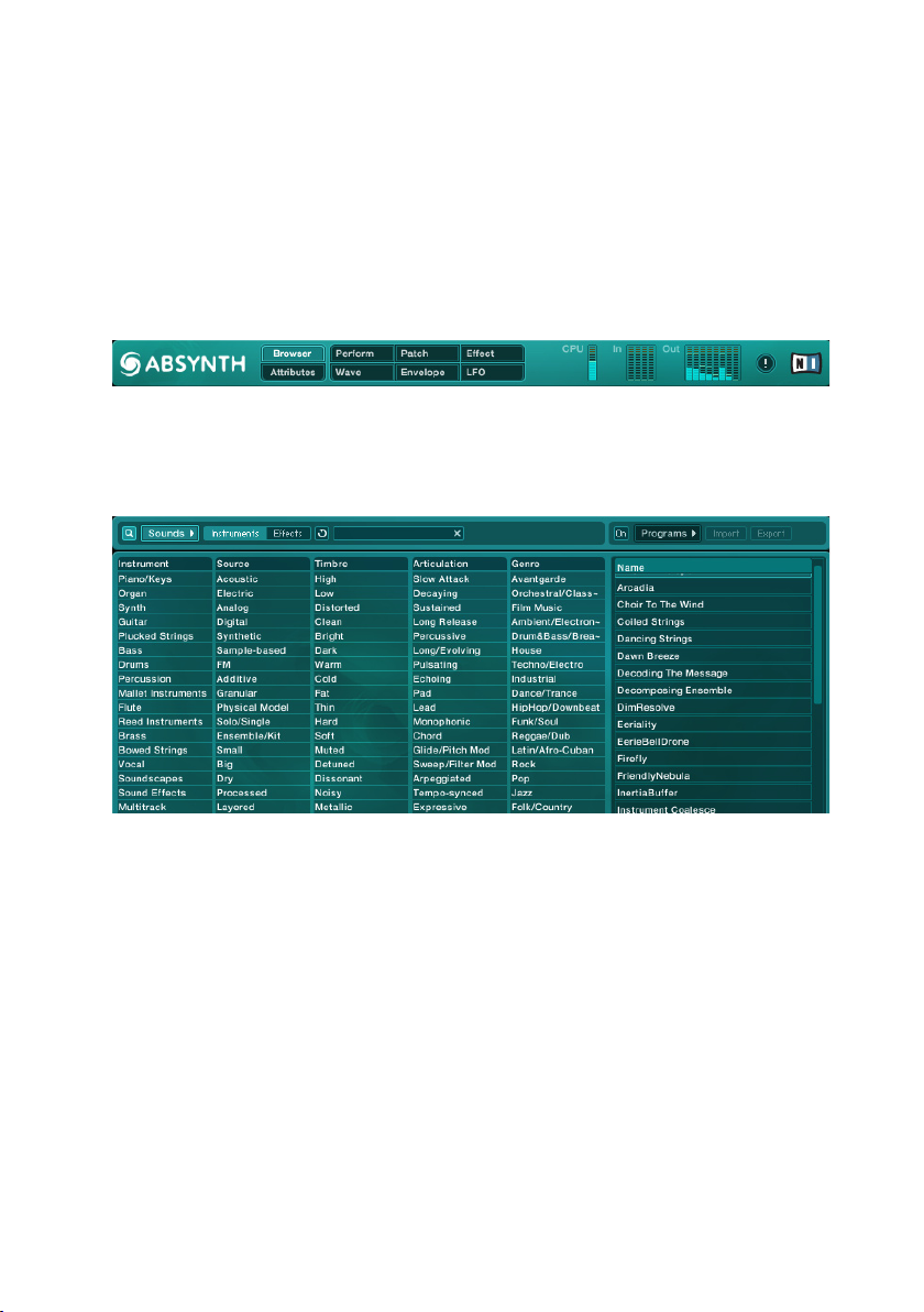
3.3.2. Browser & Attributes Window
Searching for a specic sound in the Browser Window quickly leads to suc-
cess: you simply choose certain characteristics that the sound is supposed to
exhibit and ABSYNTH 4 quickly comes up with the appropriate results from
the database. Attributes that dene the sound are the basis for this search
function. We have already attached Attributes to all of the sounds provided
by the ABSYNTH 4 library. You should also assign Attributes in the Attributes
Window to the sounds that you produce describing them as closely as possible. The effort is worth it because ABSYNTH 4 integrates your sounds into
the search, and the benets of your work will become more obvious as you
progress. There is more on the Browser Window and Attributes Window in
section 4.10.
(1) Sounds Button
(2) Instruments Button
(3) Effects Button
(4) Clear Button
(5) Search Term Field
(6) Programs Button
(7) On Button
(8) Import Button
(9) Export Button
(10) Categories
(11) Attributes
(12) Search Results
Page 15
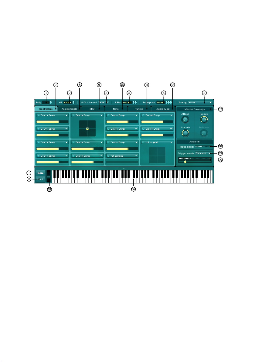
3.3.3. Perform Window
The Perform Window manages all control signals “outside” of ABSYNTH 4.
Here, MIDI signals and automation information from host software are distributed into different Macro Controls and are then readily available throughout
ABSYNTH 4. Furthermore, you can draw upon different global settings in the
Perform Window that, for example, affect the polyphony or internal tempo.
There is more to learn about the Perform Window in section 4.9.
(1) Voice Control
(2) Damping Control
(3) MIDI Channel Control
(4) Tempo Control
(5) Transpose Control
(6) Tuning Popup Menu
(7) Controllers Tab
(8) Assignments Tab
(9) MIDI Tab
(10) Note Tab
(11) Tuning Tab
(12) Audio Mod Tab
(13) Sustain Switch
(14) Hold Switch
(15) Pitchbend Wheel
(16) Piano
(17) Master Envelope Area
(18) Input Level Meter
(19) Trigger Mode Popup Menu
(20) Threshold Control
Absynth 4 – 15
Page 16
16 – Absynth 4
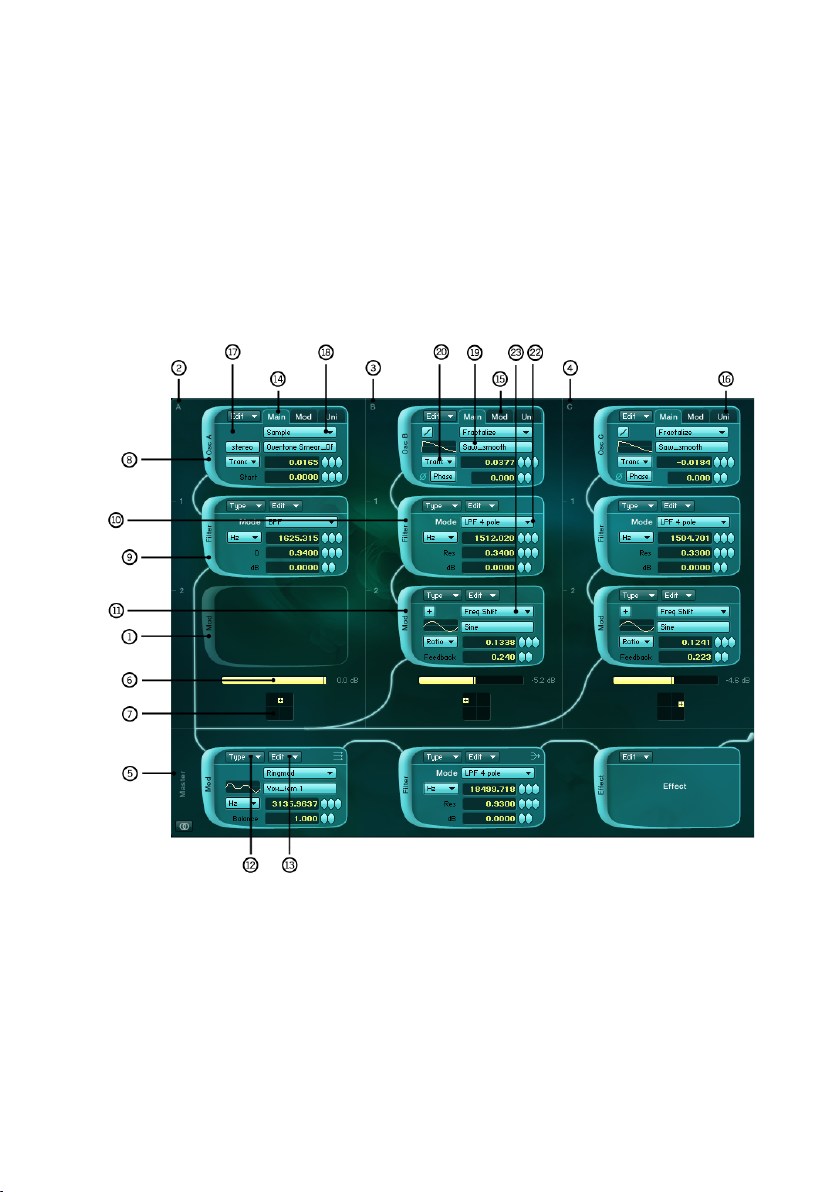
3.3.4. Patch Window
The Patch Window is where you start to design new sounds: this is where
you create the structure of the sound, by choosing the type and order of the
oscillators, lters, and other modules. You can transform ABSYNTH 4 into
completely different instruments by changing the assembly in the Patch
Window. On top of that, you are calling upon elementary functions from the
Modules in the Patch Window. This is where you can also switch over to the
Wave Window and produce waveforms there or switch to the Envelope Window
by using one click to work on an envelope. You will read more on the Patch
Window in section 4.4.
(1) Module (empty slot)
(2) Channel A
(3) Channel B
(4) Channel C
(5) Master Channel
(6) Channel A Level Control
(7) Channel A Pan Control
(8) Oscillator Module
(9) Modulation Module
(10) Filter Module
Page 17
(11) Waveshape Module
(12) Type Popup Menu
(13) Edit Popup Menu
(14) Main Tab
(15) Mod Tab
(16) Uni Tab
(17) Anti Alias Switch
(18) Synthesis Popup Menu
(19) Waveform Popup Menu
(20) Frequency Popup Menu
(22) Filter Mode Popup Menu
(23) Waveform Popup Menu
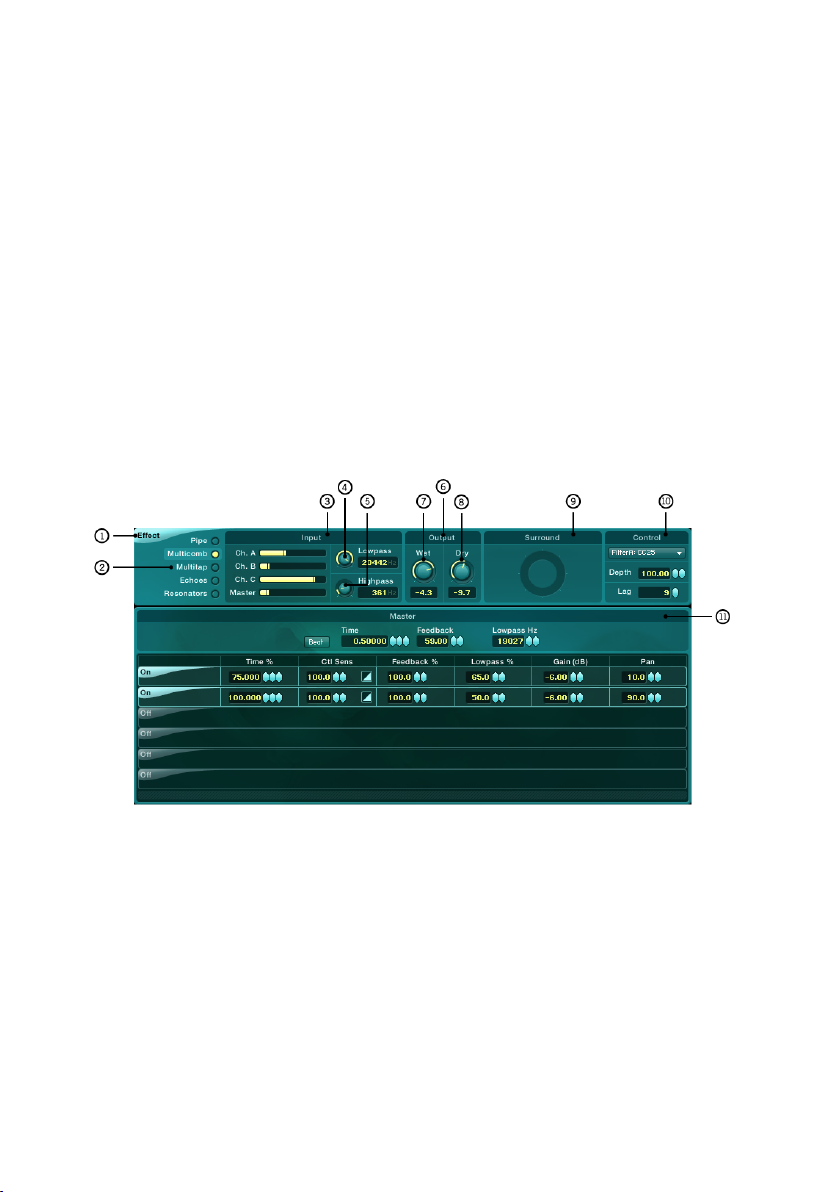
3.3.5. Effect Window
The Effect Window helps you determine which effect type you would like to
use and how this effect is supposed to change the sound. There are ve different effects to choose from whilst numerous parameters allow for a detailed
adaptation of the sound. This is the right place to come for producing effects
whether you are making a subtle echo or a psychedelic haze of delay. There
is more on the Effect Window in section 4.5.
(1) Effect Switch
(2) Effect Mode Selector
(3) Input Mix Area
(4) Input Lowpass Frequency
Control
(5) Input Highpass Frequency
Control
(6) Outout Mix Area
(7) Wet Level Control
(8) Dry Level Control
(9) Surround Area
(10) Control Area
(11) Effect Control Master Area
Absynth 4 – 17
Page 18
18 – Absynth 4
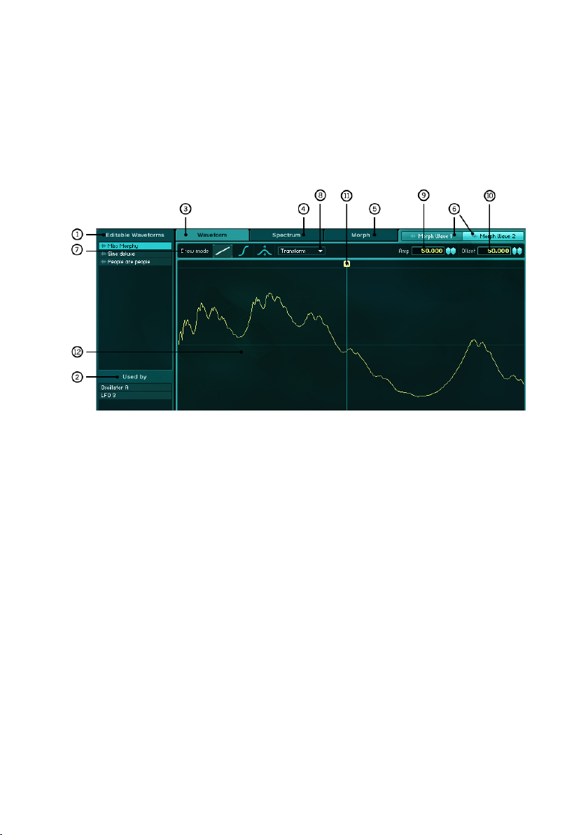
3.3.6. Wave Window
You work on all of the Waveforms or Waves in the Wave Window of ABSYNTH
4. These Waveforms play a central role in ABSYNTH 4 because they provide
the foundation for numerous modules. For example, Waveforms, which you
create and change in the Wave Window, come into use within oscillators,
LFOs, modulation and waveshaper modules. You will learn more about the
Wave Window in section 4.6.
(1) Wave Selection Area
(2) Wave Usage Area
(3) Waveform Tab
(4) Spectrum Tab
(5) Morph Tab
(6) Morph Wave Selection Tabs
(7) Draw Mode Tools
(8) Transform Popup Menu
(9) Amplication Control
(10) Offset Control
(11) Edit Anchor
(12) Wave Display Area
3.3.7. Envelope Window
The Envelope Window is where you prepare all of the envelopes used in
ABSYNTH 4. To modulate, you can apply whichever parameters you like to the
envelopes. This allows you to arrange your sounds in a very lively and dynamic
way. Envelopes are thus another important medium next to waveforms for
designing complex sound progressions or subtle modulations. There is more
to learn on the envelope window in section 4.7.
Page 19
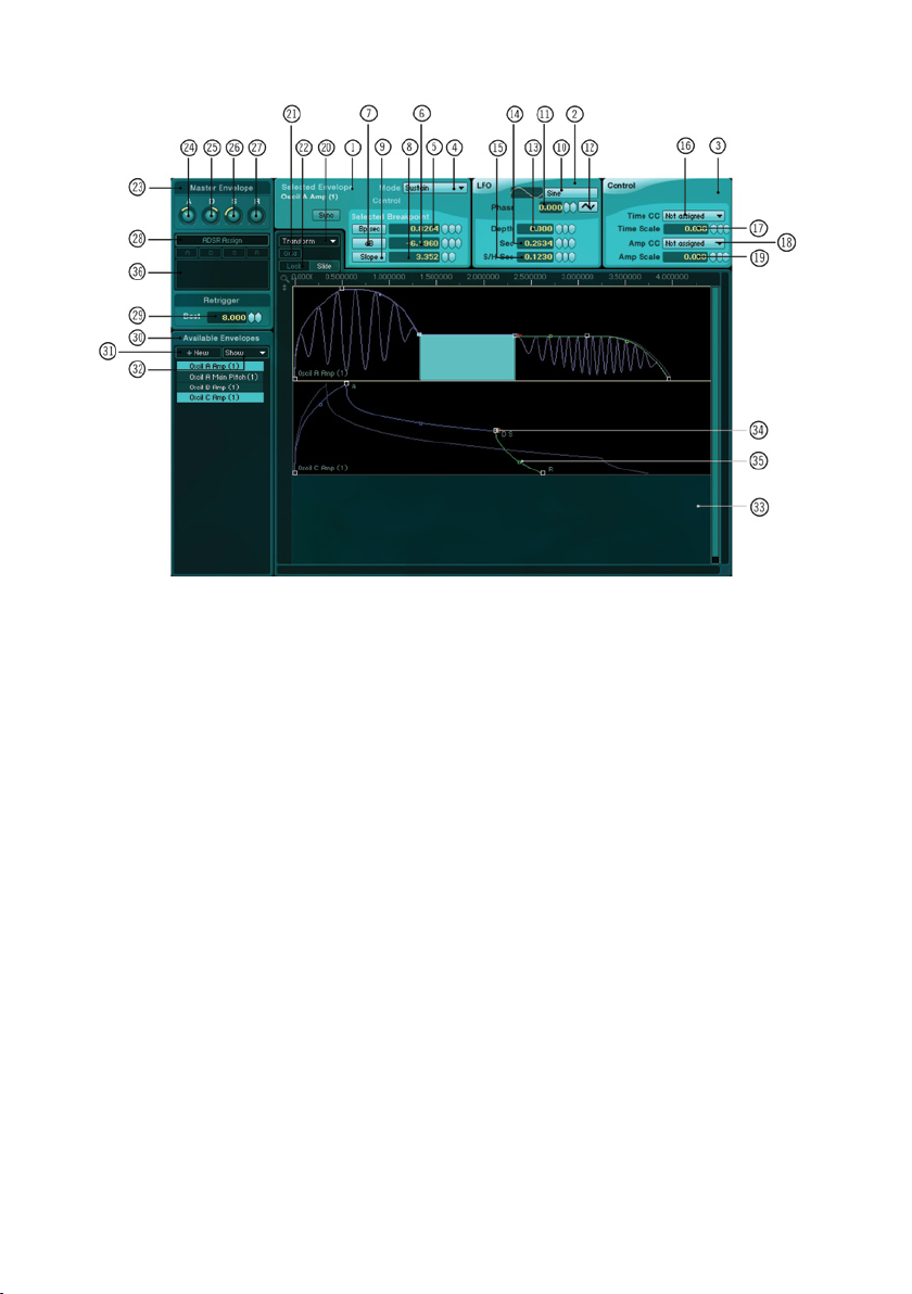
(1) Envelope Area
(2) LFO Area
(3) Macro Control Area
(4) Envelope Mode Popup Menu
(5) Breakpoint Time Control
(6) Breakpoint Amplitude Control
(7) Breakpoint Amplitude Switch
(8) Breakpoint Slope Control
(9) Breakpoint Slope Switch
(10) LFO Waveform Popup Menu
(11) LFO Phase Control
(12) LFO S&H Switch
(13) LFO Depth Control
(14) LFO Rate Control
(15) LFO S&H Rate Control
(16) Time Macro Control Menu
(17) Time Scale Control
(18) Amplitude Macro Control Menu
(19) Amplitude Scale Control
(20) Transform Popup Menu
(21) Grid Switch
(22) Lock/Slide Switch
(23) Master Envelope
(24) Master Attack
(25) Master Decay
(26) Master Sustain
(27) Master Release
(28) ADSR Assign Switch
(29) Retrigger Control
(30) Envelope List
(31) New Envelope Button
(32) Show Envelope Button
(33) Envelope Display
(34) Breakpoint Handle
(35) Breakpoint Slope Handle
(36) Zoom Handle
Absynth 4 – 19
Page 20
20 – Absynth 4
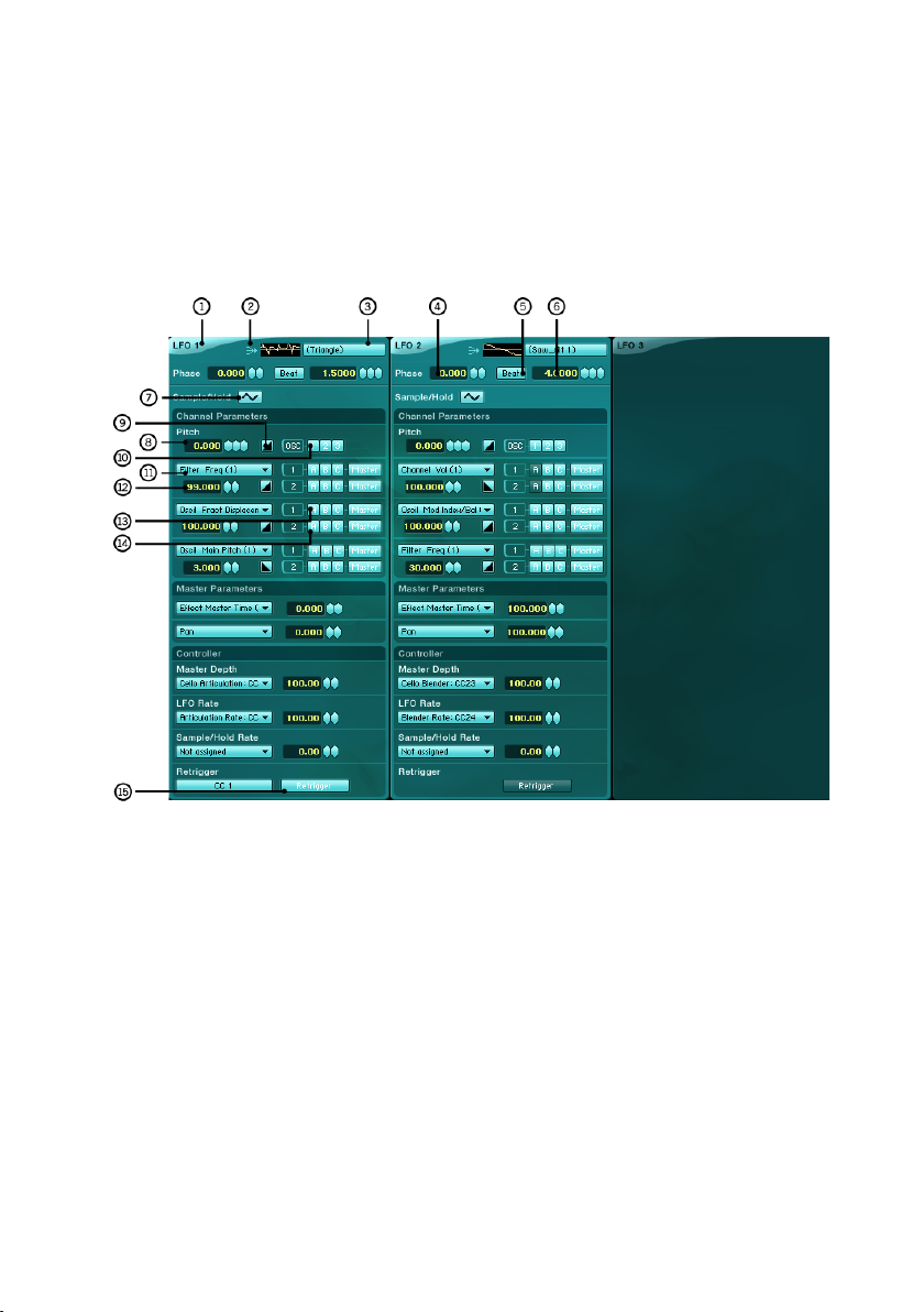
3.3.8. LFO Window
The LFO Window is where you manage the settings for the three freely usable LFOs as well as set the goals of the modulation signals that you have
produced. The possibilities of the LFOs are multi-faceted: for example, you
can use them for effects like Tremolo and Vibrato or for automated voyages
into the stereo or surround panorama. Read more about the LFO Window in
section 4.8.
(1) LFO Switch
(2) Mono/Poly Switch
(3) Waveform Popup Menu
(4) Phase Control
(5) Rate Switch
(6) Rate Control
(7) S&H Switch
(8) Vibrato Depth Control
(9) Vibrato Inversion Switch
(10) Vibrato Channel Switch
(11) Modulation Target Popup Menu
(12) Modulation Amount Control
(13) Modulation Channel A Switch 1
(14) Modulation Channel A Switch 2
(16) Retrigger Switch
Page 21

3.4. Quick Intro
This chapter introduces you to the fundamental steps for operating ABSYNTH
4. First you will learn how to select and load a sound from the library in the
Stand-Alone Version. The automation of your Audio-MIDI-sequencer can then
be used to control the parameters in ABSYNTH 4. The second section on
chapter 3.4.2 provides an introduction to sound design. Meanwhile, chapter
3.4.3 enables you to produce your own Waveforms and introduces Wave
Morph, a new feature for ABSYNTH 4.
3.4.1. Loading and Playing Sounds
In this section, you will rst learn how to load a sound with the browser in
Stand-Alone mode and then how to play the sound with a keyboard.
Stand-Alone Mode
First make sure that you already have the Stand-Alone Version of ABSYNTH
4 installed on your system and that the audio and MIDI interfaces are set
up. You can also catch up on this step later (guidelines for that are found
in the separate installation instructions) and continue with the quick intro if
you have not yet set up your audio and MIDI gadgets to use with ABSYNTH
4. If you happen to not have your MIDI keyboard hooked up, for example, if
you are sitting with your notebook on a plane, you can still operate ABSYNTH
4: the Perform Window offers an Onscreen Keyboard, and you just use your
mouse to strike the keys.
OK so far? Let’s start up ABSYNTH and we will get started.
As an example, we will search for a sound for a lm. We have a piano unlike
any other in mind, a piano that is accompanied by mysterious, oating sounds.
The ideal sound would be one that continues to change even after the note
is played so that it creates a strange atmosphere. Also, we want the sound to
utilize the surround capabilities of ABSYNTH 4. We are working on lm music
and must operate using multi-channel lm score formats.
We could now search the entire ABSYNTH 4 library for the right sound and
listen to each and every one. But that would be quite tedious, and by the time
we actually nd something tting, we may have forgotten our musical idea.
This is why we use the Browser and the so-called Attributes to track down
the right sound. The Browser is a new feature of ABSYNTH 4. It offers an
environment in which you can search for sounds quite intuitively. You do not
have to recall abstract things like preset names or even numbers. In fact, you
can just select terms that describe the desired sound from a list and then
Absynth 4 – 21
Page 22
22 – Absynth 4
use them as search criteria. These descriptive terms are called Attributes
in ABSYNTH 4. Essentially, Attributes are tags that you can attach to your
sounds, which also give information about the properties of your sounds. The
more precisely you specify your designated sound when selecting attributes,
the closer you narrow down the sounds in question until very few are. The
requirement for this type of search is that the sounds carry Attributes. The
sound designers at NATIVE INSTRUMENTS have already applied Attributes
to the sounds installed in the ABSYNTH 4 library, so your search can begin
immediately.
Normally, ABSYNTH 4 shows the Browser Window directly after starting up.
If not then you must call it up yourself. To do this you click on the Window
Selection Area in the Navigation Bar and then choose the Browser Tab. The
Browser Window is shown underneath the Navigation Bar.
You can see that the Browser Window is divided into several columns. The ve
columns on the left make up one group called the Database View. The heading
describes the Categories, below are the Attributes. Click with your mouse on
the chosen eld in order to select an Attribute. The eld is then highlighted
to show that the Attribute has been selected. To deselect an Attribute simply
click on the eld again.
On the right, we nd the Search Result List. In this function window thethe
browser displays the search results. It is also divided into columns that contain
information about the selected sounds. Besides the names of sounds, the
Search Result List can display an individual sound’s Rating, and also display
the results according to the criteria of the heading.
Page 23
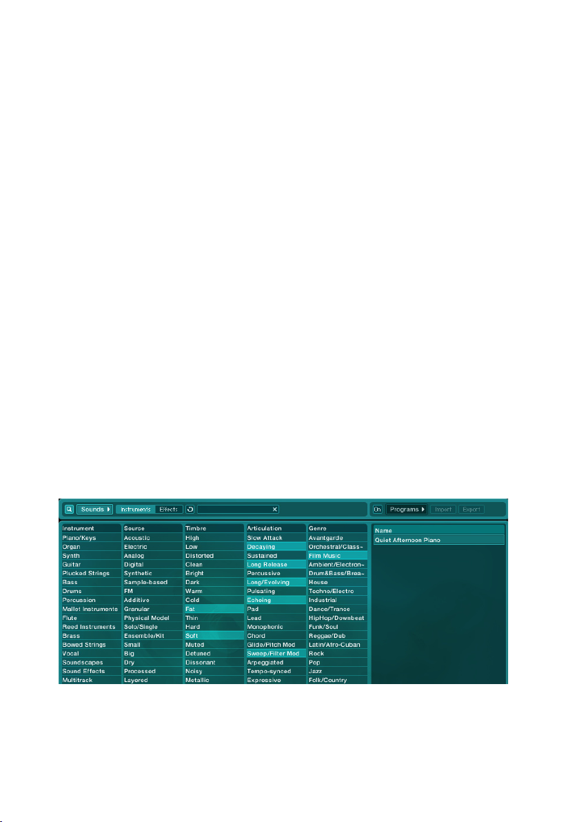
Let us now start searching for our sound. You will nd the different synthesizers in the rst column of the Database View, which is titled Instrument. This
does not just include instruments but also effects and voices. We are looking
for a piano and therefore choose the Attribute Piano/Keys from the top of the
list. Now take a look at the. Now take a look at the Search Result List: the list has become shorter
because all the sounds that are not marked by the Attribute Piano/Keys have
disappeared from the list. You can specify the basic character of a sound in
the next column titled Source. Here you will nd entries that lead to a certain
synthesizing process, for example FM or Physical Model, but also general
Attributes like Processed, Layered and Surround. We will try our luck with the
last three mentioned. Go ahead and add the Attributes Digital and Synthetic
to the search. You will see a denitively shorter list of sounds in the Search
Result List appears. As you can see, the more Attributes you pick, the more
you narrow down the search and the fewer sounds ABSYNTH 4 will offer you
in the Search Result List. Attributes that describe sound colors can be found
in the category called Timbre. It may include, for example, expressions like
Distorted, Warm and Hard, but also terms that relate to material qualities or
to the vibe. Let’s choose Fat, Soft and Exotic. The column Articulation contains Attributes that link to the playing style or application area of the sounds.
Descriptions of the keystroke behavior, decay length and what happens while
you are playing are also found here just like the familiar sound categories
Lead or Pad. Click on Decaying, Long Release, Long/Evolving and to be safe
also Echoing and Sweep/Filter Mod.
You can see a selection of musical genres in the last column titled genre.
Remember: we are working on a lm soundtrack, so Film Music is the obvious
choice. You can also select Ambient/Electro if you like.
Now look at the Search Result List. Here ABSYNTH 4 only offers you a single
sound, namely the one that contains all the chosen Attributes. “Quiet Afternoon
Absynth 4 – 23
Page 24

24 – Absynth 4
Piano.“ Double click on this entry in the Search Result List in order to load
the sound. Now play several keys on your MIDI keyboard. You hear a sound
that corresponds very closely with the demands set forth in the beginning:
a type of piano, accompanied by mysterious sounds, which produces its full
effect when played on a surround system. You do not necessarily need to set
all of the Attributes named in this manual to get to this type of sound. From
time to time, you will see that fewer Attributes will lead to good results. This
also applies to situations where ABSYNTH 4 does not deliver any hits at all.
In such cases, you can expand the search spectrum by deselecting some of
the Attributes until usable results are shown.
3.4.2. Creating Own Sounds
ABSYNTH 4 comes with an extensive selection of different sounds. You
have just learnt how to load and play the sounds from the existing library in
the previous chapter, but you can also create your own sounds quickly and
intuitively. This chapter teaches you how to build your own polyphonic lead
sound for several voices: you will learn how to combine the Modules in the
Patch Window and how to modulate envelope parameters. We will use the
Stand-Alone Version of ABSYNTH 4 for these purposes.
Preparations
Start up the Stand-Alone Version of ABSYNTH 4. It is best to begin working
on a new sound with an empty Preset. Choose New Preset from the le popup
menu in the navigation bar to create an empty Preset. Select the “no” icon
if a dialog window appears that asks whether to save or discard changes to
the current preset.
As previously mentioned in the introductory section 3.2.1, the Patch Window
is used for creating the foundation for any sound within the semi-modular
design of ABSYNTH 4. Click on the area titled Patch Window in the Window
Selection Area located in the Navigation Bar. The Patch Window is shown
underneath the Navigation Bar. At least one Oscillator Module must be ac-
tive for ABSYNTH 4 to produce an audio signal. Normally, the Oscillator
Module in Channel A is already engaged when you call up an empty preset.
The waveform is set to Sine. All the other Module Slots are free (remember:
Module Slots are the framed areas in the Patch Window in which you can
call up the Modules). This means the remaining Modules are not active. We
will now learn how to integrate the Patch Window with further Modules and
change the settings of the Modules.
Page 25
Conguring the Module
You should now be able to play thisnow be able to play this be able to play this Oscillator Module: when you press a key
on your MIDI keyboard, the sine wave makes a sound that corresponds to the
frequency of the note played. We will now try changing the waveform of this
oscillator, as we want to create a stronger lead sound. Click on the Waveform
Popup Menu that you see on the right, next to the small waveform diagram.
A window with a list of names opens up that refer to different waveforms.
Choose from one of the waveforms, and you will see that the waveform representation changes automatically in the Oscillator Module.. You can play the
selected waveform immediately through your MIDI keyboard, and this will allow
you to hear whether the resulting sound meets your expectations or not. This
is how you can quickly nd a waveform that is appropriate to your needs.
We will pick the waveform Square_real as our lead sound. You can already
hear how sharp and assertive the waveform sounds when it starts to play.
Therefore, it easily makes a strong lead sound, which will not be lost amongst
a compact mix.
We will now add another oscillator to give the sound even more character. To
do this, call upon a second Oscillator Module by clicking on the extended left
edge of the Module Slot B that has Osc B written in it.
Absynth 4 – 25
Page 26

26 – Absynth 4
To begin with, a standard sine wave is active even in this Oscillator Module.
Here you can replace the sine with the waveform Saw_lt2 by repeating the
steps described above for choosing a waveform. Listen repeatedly to the
sound that you have created during the in-between steps to get a feeling
for changing the sound with small steps. We will now transpose the second
oscillator by one octave, in order to separate it from the rst one. You can
see the Transpose Control - which shows “0.0000” at the moment - next to
the Transpose Pop-Up Menu in the Oscillator Module B. This value describes
the tone pitches of the oscillators in relation to the tone pitch of the note that
you play on your keyboard. There are three small hexagons, the Edit Combs,
with which you can change the tone pitch of the oscillators in different size
steps: click with your mouse outside the left edge of one of the hexagons,
and scroll the mouse slightly upward. This is how you raise the tone pitch
in halftone steps. Set this value at 12.0000, which correlates to 12 whole
tones, basically one octave. So your second oscillator always sounds one
octave higher than the rst.
Now put the second oscillator out of tune a bit to make the sound wider
and more powerful. To do this, you have to raise the value a few cents in
the Transpose Control of Oscillator Module B (remember: a halftone step in
the equally tempered tone system is divided into 100 cent-steps). This time
choose the middle hexagon and increase the value in the Transpose Control
to 12.1100. This minor detuning produces a subtle beat in your sound and
is how lead sounds and pads become livelier and stronger.
Now we will treat the sound with a lter in order to reduce the high frequencies a bit. For this we require a Filter Module. Activate the Filter Module by
clicking on the extended left margin Module Slot (marked Filter) in the Master
Channel. The Filter Module is now active. You will recognize the signal ow of
your sound by the lines that connect the three active Modules. The signals of
both Oscillator Modules are then combined in the Master Channel and now
run together through the Filter Module. Now select the Filter Mode LPF 2
Pole in the Filter Mode Pop-Up Menu. Next raise the value to 7000.00 Hz in
the Frequency Control through the three Edit Combs. Shortcut: you can enter
the value directly into the Frequency Control via keys. Simply click directly
on the shown value from the Frequency Control, which then is selected and
highlighted in color. Decide on your desired frequency and press the “enter”
button on your keyboard. You will notice that with this lter setting, the sound
is now softer.
Page 27
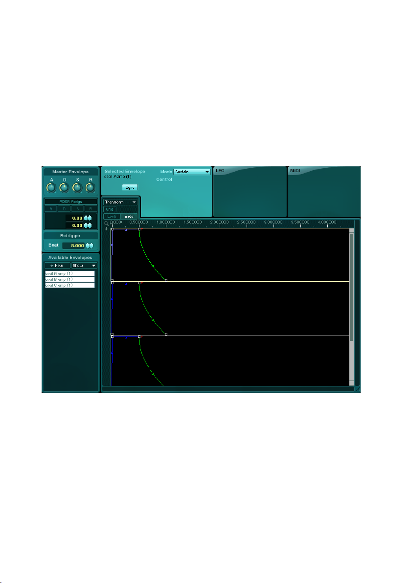
Modulation of Filters
Next we are going to modulate the frequency envelope to make the sound
more interesting. The term “modulate” refers to the automated change of a
parameter through another module. We will rst have to setup the prerequisites
to create an automated parameter change. To do this, we have to connect a
modulation source with a modulation goal. You already know your modulation
goal: the Frequency Envelope of ABSYNTH 4. You can work on the Frequency
Envelope in the Envelope Window, as with all envelopes in ABSYNTH 4, by
clicking on the area marked Envelope in the Window Selection Area of the
Navigation Bar. The Envelope Window is shown beneath the Navigation Bar.
The Envelope Window is where you can produce and work on all Envelopes,
which are used in the preset that you just loaded. The envelopes in ABSYNTH
4 produce a signal for modulating a parameter according to its outlined course.
When you play a sound, this course is channeled and the uctuating value of
the envelope changes the activated parameter.
You can see all the parameters that already have existing envelopes in the
Envelope Selection List - the area listed with the header Available Envelopes
on the left side of the Envelope Window. In this list you will nd, for example,
the Amp Envelopes of both oscillators: Oscil A amp and Oscil B amp.
We actually want to work on the Frequency Envelope of the lter. First we
must add this envelope, as it does not yet appear in the list. Click on the
Absynth 4 – 27
Page 28
28 – Absynth 4
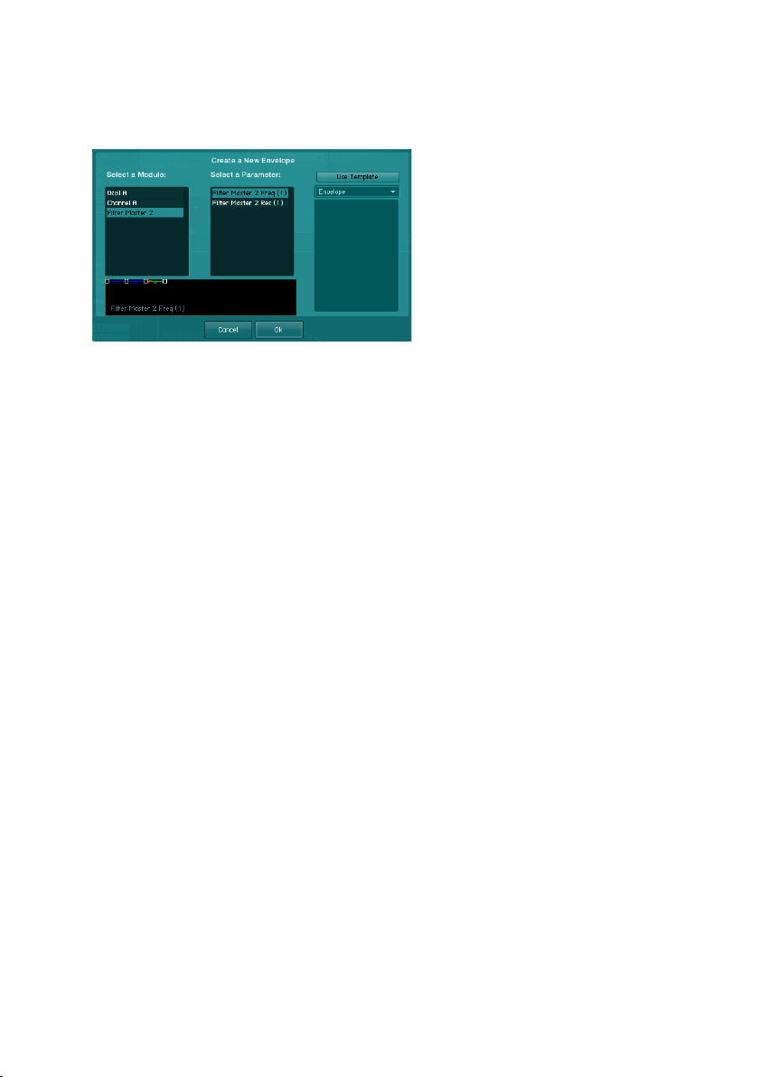
New Envelope Button to add an envelope to the Envelope List. You will see
a list of loaded Modules in the New Envelope Menu, which is titled Select a
Module. Choose the entry Filter Master2 and click Ok.
The newly added envelope now appears in the Envelope Selection List and is
already selected. Now hide all the other envelopes from the display (Envelope
Display) located next to the list. To do this you choose the entry Filter only
from the Show Popup Menu above the list. Now only the Filter Envelope in
the Envelope Display should appear.
As you can see, the points where the envelopes change their direction are
marked with small squares. These squares are called Breakpoints. You can
work on the breakpoints as you see t: add new breakpoints to the envelope,
delete breakpoints, or relocate them as in our case. If you move a breakpoint
to the right or left, the envelope’s position changes on the timeline axis. If you
move the breakpoint up or down, you change the amplitude of the envelope
and, in so doing, the value of the modulation signal at this point in the course
of the envelope.
To move a breakpoint, click on the small square and drag it with a pressed
down mouse button to the desired new position. We would like to modulate our
lter with a rate of 300 Hz. To set this value simply drag the rst breakpoint
of the envelope downward until it has reached the value of 300.00 Hz in the
Frequency Control of the Selected Breakpoint Area.
Page 29

When playing your sound you will notice that the lter closes for a brief moment
after the note is struck, then opens again: the sound very quickly becomes
duller and less stellar; more importantly, however, the modulation makes it
livelier and more diverse. Feel free to move around more breakpoints to learn
how to inuence your sound.
The Le adsound has now been completed and can be stored as a
KoreSound.
Saving the Sound
Click on the Save Button in the Navigation Bar to save your newly designed
sound as a Preset in the KoreSound format (*.ksd). A dialog will open up.
Here is where you can choose the folder for your index structure.
We recommend that you save the sound in the folder “My Sound” of ABSYNTH
4 or in one of the sub-categories. This automatically integrates the sound into
the KoreSound database of ABSYNTH 4 and is readily available in the same
way as the sounds provided in the library in the Browser Window. You can
read more on the Browser Window in section 4.10.3 of this manual. There
you will also nd information on Attributes, which you should add to each
newly designed sound en route to the KoreSound database. Of course, this
quick introduction merely gives you a brief insight into the sound synthesis
in ABSYNTH 4. Continue your own research by following the instructions
detailed above. For example, use an additional oscillator to make the sound
even livelier. Perhaps you can add more lters and envelopes - the possibilities are almost endless.
Absynth 4 – 29
Page 30
30 – Absynth 4
3.4.3. Producing and Morphing Waveforms
In this section you will learn how to merge Waveforms into a Morph Wave,
with the help of the new function Wave Morph. With it you can morph back
and forth between waveforms - between a sine wave and saw tooth wave,
for instance. This is not just a simple cross fade of both original types but
more of a non-linear combination, which produces delightful musical effects
by pushing and pulling the Waveforms during morphing. In the following section, a step-by-step guide will acquaint you with this mighty instrument for
sound design.
Producing a Morph Wave
Start ABSYNTH in the Stand-Alone mode to begin working on a new morph
wave. Create a new empty patch following the instructions in the previous
section. You can also set up a new patch by pressing the key combination
STRG+N (Windows) or Option+N (Mac OS X). Answer the question with a
“No” when asked whether to save changes to your settings.
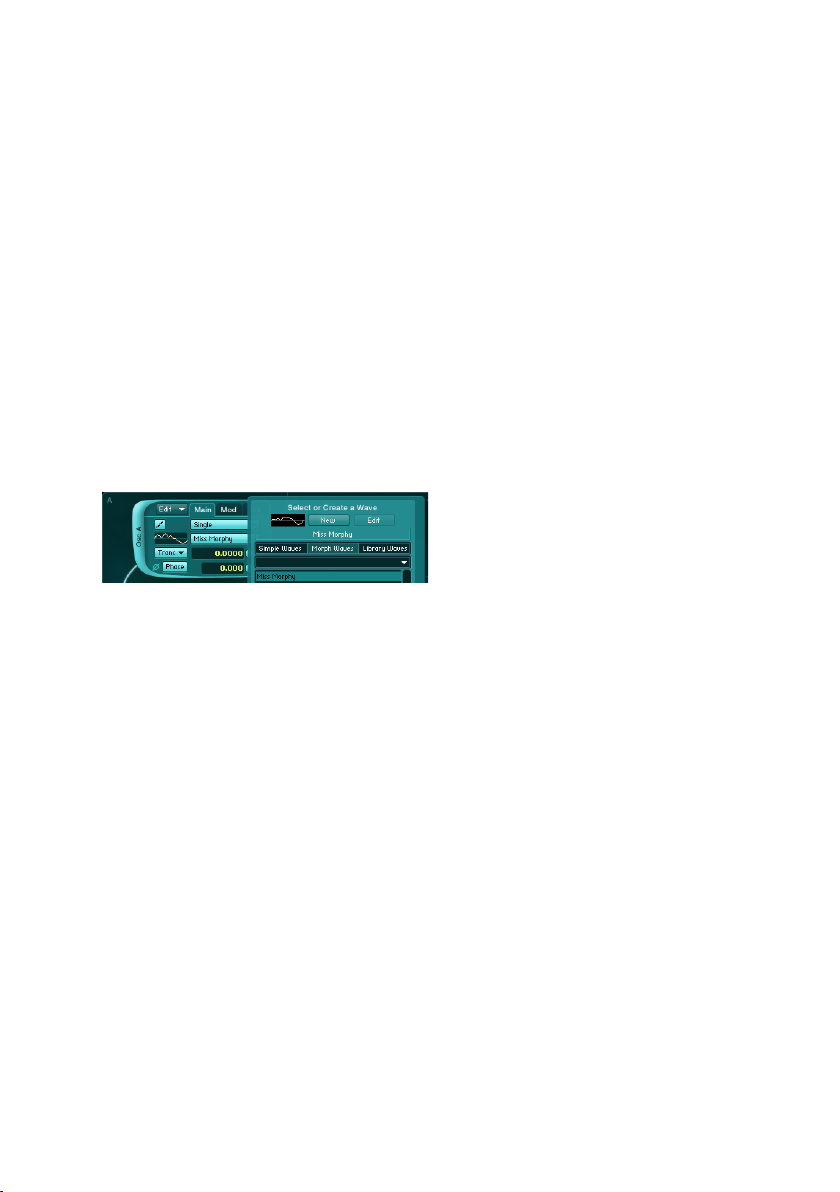
Now open the selection window with the list of accessible waveforms by
clicking on the Waveform Popup Menu of the only active Osillator Module. In
this window, single-click the category Morph Waves. Choose the entry Miss
Morphy from the list of Morph Waves. This Waveform will now serve as a draft
for your own Morph Wave. Next, click on the New Wave Button to load a copy
of the selected Morph Wave into the Wave Window. ABSYNTH 4 immediately
switches the window view to Wave Window. You will nd the list of Available
Waveforms List on the left edge of the Wave Window. This list contains all
the Waveforms that you have created from other Waveforms via the New Wave
Buttons. You will see that your new Waveform is currently the only one there,
which is why it was selected in the rst place. Click with the mouse on the
name of the waveform: you can now change this name and conrm the new
name by pushing Enter.
Page 31

Notice that only the modules using the Waveform are shown below the list.
Right now, only the Oscillator Module is shown, from which we activated the
Waveform Popup Menu, but this feature is useful to gain an overview of which
Waveform you are working on, in the case of multi-layered sounds.
Executing Waveforms
Next to the Available Waveforms List you will see an area with three Tabs:
Waveform, Spectrum und Morph. The Morph Tab is active because you have
created a Morph Wave; the tab has no function when you work on a Waveform
of the Simple type. To the right of the Morph Tab you will nd two Buttons
that are marked with stylized waveforms, as well as the numbers 1 and 2.
These two Buttons make up the Morph Wave Selection Toggle: a toggle with
which you can switch back and forth between both waveforms contained in
your Morph Wave, when the Tabs Waveform or Spectrum are selected.
Now we will change the rst of two waveforms. Simply open the Transform
Popup Menu by clicking on it. Then select the last entry: Clear. Choose the
Line Draw Tool to the left of the Transform Popup Menu and press the mouse
button to drag the left end of the horizontal line all the way down. Next drag
the right end of the line in the same way but upward. The result should show a
line from the left bottom corner to the top right - a classic saw tooth curve.
Absynth 4 – 31
Page 32

32 – Absynth 4
Next switch to the second waveform by clicking the button marked with the
number 2 in the Morph Wave Selection Toggle. Here a sine wave is supposed
to be utilized. However, its curve is hard to draw using the line-tool. Instead
of drawing the curve on your own, you simply load the sine wave from the
library with the waveforms provided. To do this, again select the entry Load
in the Transform Popup Menu. It will open the same list of waveforms. Choose
the category Simple Waves - only a single sinus wave is needed, not a Morph
Wave. Choose the list entry Sine and conrm the selection with a click on
OK. The dialog will close and the sinus-curve is loaded.
We cannot go into every possibility for working on loaded waves in this quick
introduction. For example, we have not yet looked at the function Spectrum
Tab. But you will nd information on all the tools and functions in the Wave
Window in chapter 4.6 of this manual.
Changing the Morph-Parameter
We have now created two waveforms independently of each other. But now
we will bring these two waveforms together. Switch to the Wave Window with
one click on the Morph Tab in the Morph View. Here you can see the two
individual waveforms Wave 1 and Wave 2 in both upper waveform indexes.
Right down at the bottom you can see the result of the morphing which is
used in the actual sound production.
You should always keep playing some tones on your MIDI keyboard while you
change the desired parameters in this process. That way you can always hear
Page 33

immediately how the changes you make affect the sound.
You can modify two parameters in the Morph View: the mix relationship between
both waveforms, and the curves of the single waves. The latter involves a type
of Wave Morphing that separates the waves by a slight cross fade. You can
change the curve of the waveforms with Anchor Points, which are represented
in the Waveform display by vertical lines with attachments at the upper end.
When you rst call upon a Morph Wave, there are two active Anchor Points.
But for our example, we will raise the number of Anchor Points to three by
choosing the entry 3 from the Anchor Points Popup Menu in the upper left
corner of the Morph View. Now you can evenly spread the anchor points over
the length of the waveform by dragging (with the mouse button held down)
the heads marked with letters. Use the following diagram for guidance:
Now we turn to the Transition Control, which is located between the second
waveform and the result of the wavemorph just underneath. The given value,
set at 50, causes each wave to inuence 50 percent of the waveform, which
results in a sinus-curve that climbs slightly like a rising saw tooth. Reduce
Absynth 4 – 33
Page 34

34 – Absynth 4
the value now to 0 by clicking on the Transition Control with the mouse and
dragging it downward holding the button. What remains is solely the saw tooth
from the rst waveform. You can see a spitting image of the second Waveform
when you raise the value to 100 by dragging upward.
As you can tell, this does not yet deal with non-linear bended morphing as
mentioned previously, but rather with simple linear cross fading. This is because
of the even distribution of Anchor Points in both waveforms. Set the Transition
Control again to the value of 50 in order to attain an even mix relationship.
Finally, drag the middle Anchor Point of the upper waveform to the left and
the middle Anchor Point of the lower one to the right. Observe how the result
of the morphing then changes.
What happens here? The area between the Anchor Points A and B (as B and
C, C and A) now has a very different length in both waveforms. Despite the
variations between them, however, these areas maintain a relationship with
one another as a result of wave morphing. In other words, the short section is
broadened and the long section is jolted. You can again determine the mass
Page 35

of the bend in the Transition Control: the area between Anchor Points A and
B of the rst waveform, all the way to the point equidistant between Anchor
Point B of the rst and Anchor Point B of the second waveform, is stretched
out by a value of 50. The result is a sine-shaped section to the left in the
ending Morph Wave. The area between Anchor Points A and B of the second
waveform rst begin here and are jolted this way. The result is the straight line
rising to the right in the Morph Wave. You get the familiar single waves when
dragging the value for Transition back to 0 or to 100; it is just the transition in
between that is signicantly multi-faceted. There are many other ways of using
Wave Morphings that we cannot cover in this quick introduction; for example,
with just four Anchor Points you can produce exact, elaborate transitions. You
will nd more in-depth Wave Morphing information in the reference section
of this manual in chapter 4.6.5.
4. Reference
In this part of the handbook you will nd instructions on how to use ABSYNTH
4: explanations of the individual work areas and their uses, descriptions of the
parameters, and instructions on how to make practical use of the functions.
Here you can look up questions such as – for example – which effect you can
use in order to achieve a particularly strong sound. In short: Here you can nd
out how to use the different features of ABSYNTH 4 and how to then bring
the program into contact with the outside world.
4.1. Interaction with Control Features
You will nd various control elements on the ABSYNTH 4 interface, which
allow you to switch between Windows or change values. This section provides
you with an introduction to these elements and instructions for their use.
4.1.1. Windows und Tabs
Windows is the word that is used to refer to the different work areas in
ABSYNTH 4. There are eight Windows that can be accessed through the
Window Selection Area in the Navigation Bar. In order to switch to another
Window, click on its name in the Window Selection Area. These buttons
Absynth 4 – 35
Page 36

36 – Absynth 4
are called Tabs, whereas the Tabs that belong to Patch Windows are called
Patch Tabs. The Tab of the selected Window is shown a lighter hue than the
other Tabs.
Some Windows, such as the Oscillator Module, can be switched between
multiple bottom views. These bottom views can be accessed through Tabs
that are set up here as index tabs. In order to access a bottom view, click on
the Tab that you want to view. The active Tabs will be distinguished through
their color and changes in their margins.
4.1.2. Module On/Off Switches
In the Patch Window, the Module On/Off Switches option allows you to allows you to
turn individual modules on and off by simply clicking the extended left
area on the module frame. You do not necessarily need to click on the
writing, since the entire left margin area works as a button.
4.1.3. Popup Menus
Popup Menus can be found in many areas in ABSYNTH 4. These opening
and closing menus contain lists of available options. Popup Menus can be
recognized through their lightly hued appearance and the small triangle pointing downwards.
In order to choose an option from a Popup Menu, click on the lightly hued
panel. A list appears which remains open if you move the cursor. In order to
choose an entry, click the desired entry and the name of the selected entry
will appear as new writing in the Popup Menu.
Page 37

Some Popup Menus open a new window rather than placing your le in an
opening and closing list, due to the space limitation on screen. This is the
case for the Waveform Popup Menu, for example.
4.1.4. Value Fields
Value Fields contain the numerical values of parameters. The values indicated
can be changed in a variety of ways:
• Click in the eld in order to select the entry. The value appears over a
colored background. Now enter the desired value using your computer
keypad.
• The values can also be changed using the mouse by clicking on one of
the hexagons to the right of each Value Field, and then by dragging the
mouse either up or down whist pressing the button. Drag the mouse
up to increase the value and down to decrease the value. Depending
on the resolution of a value in a Value Field, you will see two or three
hexagons — the Edit Combs – next to the Value Field. By changing the
value in the left hexagon, the hexagon on the right (i.e. in front of the
decimal point or comma) will also change. With the other hexagon you
can carry out the precise installation.
• If your mouse has a scroll wheel, you can place the cursor on a hexagon and change the value indicated in the Value Field by moving the
scroll wheel. Move the wheel forward in order to increase the value and
backwards to decrease it.
• Remember that you can click on the right mouse button in the Value
Fields to bring up a context menu. Here you can assign one of the
Macro Controls to the parameter. More specic information about Macro
Controls can be found in Section 4.9.
4.1.5. Fader and Knobs
The values of parameters can be changed using different Fader and Knob
controls..
Faders are sliders; for example the faders in the Effect Window can adjust thecan adjust the
levels of input levels such as the Channel A Input Level. Knobs meanwhile
are controllers; for example in the Effect Window again, you can adjust the
Absynth 4 – 37
Page 38

38 – Absynth 4
signal proportions using the Wet Level Control and Dry Level Control Knobs.
The global envelope Master ADSR also uses Knobs.
In order to change the value of a parameter with a Knob, click on the desired
Knob and click and drag the mouse upwards to increase the value. Pull the
mouse downwards in order to decrease the value. You do not need to rotate
the Knob with the cursor. Simply dragging the mouse upwards or downwards
does the job.
If you use a mouse with a scroll wheel, you can place the cursor on a Fader or
Knob to change the installed value by moving the scroll wheel. Move the wheel
forwards in order to increase the value or backwards to decrease the value.
4.2. Stand-Alone Menu
The Stand-Alone Menu is only present if you are using the Stand-Alone Version
of ABSYNTH 4. It contains the same entries as the Navigation Bar as well as
the following additional entries:
4.2.1. Import GLO File…
Select the entry Import GLO File... in order to import sounds from older ver-
sions of ABSYNTH into ABSYNTH 4. You can then load a Soundbank from a
previous version of ABSYNTH 4 and go through the list of available sounds.
The sound selected from the list will be loaded automatically and you can play
it. Should you wish to convert this sound into an ABSYNTH 4 KoreSound, you
can save it like any other sound in the usual manner.
The Factory Library of ABSYNTH 3 has already been converted and is available via the Browser Window.
4.2.2. Options
The Options Dialog has three Tabs: General options are installed under the
General Tab. The Output Congurations can be found by pressing the Surround
Tab. The different installations for the KoreSound Databank can be accessed
via the Browser Tab.
General Tab
Two options can be turned on or off under the General Tab::
• Balance levels: When Balance levels is turned on, ABSYNTH 4 controls
the output of the three individual channels in the Patch Window so that
the main output remains constant. That is, if you were to increase the
level of one Channel, ABSYNTH 4 would automatically decrease the
levels of the other Channels.
Page 39

• Enable automatic renaming of Macro Controls: When this is turned on,
a Macro Control that has had a parameter assigned to it, takes over the
name of this parameter – but only if no other parameters have already
been assigned to it.
Surround Tab
In this Option Dialogues Tab, ABSYNTH’S Audio Output Paths can be cong-
ured. The fundamentals for constructing the Audio and MIDI interfaces can
be found in the installation handbook. For now, we will limit ourselves to an
overview of the different channel congurations. You can choose from the
following: Stereo, Stereo Wide, Surround 4.1 and 5.1, Front, Quad, Music,
Pentaphonic, Hexaphonic, Cinema, Heptaphonic and Octophonic.”0.1“ stands
for the LFE (Low Frequency Effects) or Subwoofer channel. You can turn this
channel on or off for any conguration and make the volume of your speaker
system conform to it. Here is a list of available congurations:
• 2.1 Stereo: This standard conguration delivers typical two-channel
stereo sound. The speakers are situated at 45 degrees and minus 45
degrees in this installation.
• 2.1 Stereo Wide: This conguration is easy to distinguish from 2.1
Stereo: Both front speakers are arranged at 90 degrees and minus 90
degrees. This results in a wider stereo soundscape.
• 3.1 Surround (LRS): This configuration returns to analog Matrix
surround sound. It is well known under the names of, for example,
Dolby Surround™ (home entertainment center) or Dolby Stereo™ (movie
theatre), but without a front center channel. Here, there is a central
rear channel as well as left- and right front channels.
• 3.1 Front (LCR): The conguration has an additional front-center chan-
nel, which leads to better distribution in the stereo soundscape.
• 4.1 Surround (LCRS): This conguration combines a 3.1 Surround
conguration with a front-center channel and is also known under the
name Dolby Surround Pro Logic™.
• 4.1 Quad: This four-channel conguration is based on the quadraphonic
systems that were popular with consumers in the 1970’s. The four
speakers are arranged symmetrically in a square shape.
• 5.1 Music: This ve-channel surround sound conguration is compa-
rable to top-of-the-line home theater arrangements and movie theaters
systems, known as, for example, Dolby Digital™ or DTS™. This system
provides you with three front channels (left, center, right) and two surround channels (surround left, surround right).
Absynth 4 – 39
Page 40

40 – Absynth 4
• 5.1 Pentaphonic: This conguration delivers ve-channel surround sound,
where the ve channels are arranged symmetrically in a circle.
• 6.1 Music: This conguration corresponds to a 5.1 Music conguration,
but contains an additional rear center channel. This arrangement is
used by, for example, the surround sound systems Dolby Digital EX™
and DTS-ES™.
• 6.1 Hexaphonic: This conguration delivers six-channel surround sound
where the six channels are symmetrically arranged in a circle.
• 7.1 Cinema: This conguration delivers seven-channel surround sound
as it can often be heard in lms. Well-known surround sound systems
of this type include SDDS™ and IMAX™. This conguration combines
the 5.1 music congurations with two center channels (center left,
center right).
• 7.1 Music: This conguration delivers seven-channel surround sound.
It is comparable with the 6.1 Music arrangements, but the surround
center channel is divided between the two rear channels ”surround
center left“ and ”surround center right.“
• 7.1 Heptaphonic: This conguration delivers seven-channel surround
sound, where the seven channels are symmetrically arranged in a
circle.
• 8.0 Octaphonic: This conguration delivers eight-channel surround
sound, where the eight channels are symmetrically arranged in a circle,
but (unlike in all of the other congurations) there is no LFE channel.
For any of these congurations, you can set the arrangement of the chan-
nels using the available audio outputs of the Stand-Alone Version. The audio
outputs that you congured in the Audio and MIDI Settings Dialog are at
your disposal (more specic information on this can be found in a separate
installation manual).
As long as you use ABSYNTH 4 as a Plug-in, the host will automatically choose
the correct setting for the channel in which ABSYNTH is used: a particular
Plug-in will be used depending on whether you use ABSYNTH as an instrument or as an insert effect, and whether the according channel is a stereo
channel or a surround channel.
Browser Tab
In the Browser Tab, you can determine in which folders to search for
KoreSounds. You can combine folders containing the respective Buttons or
remove folders from the list. Remember that subfolders in the selected folders
will automatically be included in the search as well.
Page 41

Should you ever make changes in this Tab, or delete/combine individual
KoreSound data using the operating system in the corresponding folders,
then you must refresh the databank. In order to do this, use the Rebuild
Database Button. (Depending on the number of available KoreSounds,
this process can be time-consuming.) Only then will the changes take
effect in the databank.
4.2.1. Help Menu
The Help Menu contains 3 options with further information about ABSYNTH 4:
Launch Service Center
This option allows you to startup the NI Service Center. This program can
activate ABSYNTH 4 as well as search for new Updates. Detailed information
can be found in the separate installation handbook.
Visit ABSYNTH 4 on the Web
This option loads the NATIVE INSTRUMENTS website in your Internet browser,
where you can access current information on ABSYNTH 4.
About ABSYNTH 4…
Choosing this option opens the About Screen where you can view the version
number and the individual serial number of your copy of ABSYNTH 4. You can
also nd the names of all of the people who worked on ABSYNTH 4.
4.2.2. Audio and MIDI Setting
With this menu point, you can activate the conguration dialog for the audio
and MIDI interfaces of ABSYNTH 4. All of the options contained in this dialog
are described extensively in the separate Setup Guide.
Absynth 4 – 41
Page 42

42 – Absynth 4
4.3. Navigation Bar
The Navigation Bar is located at the very top of the ABSYNTH 4 window. It
consists of two lines. In the top line of the Navigation Bar you will see (from
left to right) the Window Selection Area, the CPU Meter, the Level Meter
Displays, and the Panic Button. More information about these features is
available in later sections of this chapter. The bottom line includes options to
load and save sounds as well as navigate the library:
• File Popup Menu The File Menu provides options for loading new
sounds (New Sounds), for saving current sounds (Save) and for saving
the current sounds under a new name (Save as).
• Edit Popup Menu Here you will nd the following entries: Undo, Copy,
Paste. Undo allows you to reverse the most recent steps you took in
your work. With the Copy command, you can copy an envelope in the
Envelope Window and a waveform in Wave into the clipboard. Choosing
Paste then allows you to paste this copied envelope or waveform from
the clipboard to the le that you are working on.
• Sound Name Display displays the names of the sounds you have just
loaded. You can change the specied name by clicking on Sound Name
Display with the mouse. A double click selects the entire name. You
can now enter a new name.
• Previous/Next Sound Buttons With these buttons you can scan quickly
through a list of sounds. If you used Database Views to load your sound
into the Browser Window from Search Results, then a small magnifying
glass will appear in Sound Name Display. The Previous/Next Sound
Buttons then allow you to choose the previous or following Sound in this
Search Results list and load it to the system. If, however, you loaded
your sound from the File Tree View, then a small folder will appear in
Sound Name Display, and the Buttons allow you to select from the
content of the folder from which the original sound was loaded.
• Save Button The Save Button activates the same dialog for saving
current Presets under a different name to the entry Save in the File
Popup Menu.
Further instructions on loading, saving, and administration of sounds can
be found in section 4.10, which also provides an extensive description of
ABSYNTH 4’s new Sound Browser.
Page 43

4.3.1. Window Selection Area
In the Window Selection Area you can change the appearance of the ABSYNTH
4 interface by switching between individual Windows. Every Window contains a
particular working area that makes certain tools available. In order to activate
a window, click with the mouse on the Field (Tab) with the name of the desired
Window. The window view of ABSYNTH 4 changes in the new Window, the
Tab that belongs to it appears lightly hued in the Window Selection Area.
4.3.2. CPU Meter
The CPU Meter indicates the processing load being used by ABSYNTH 4. When
the computer is overburdened, distortions or other disturbances can result
during playback. To avoid this, it is worth keeping an eye on this indicator.
The processing load depends above all on two factors: the complexity of the
sound and the number of voices played. ABSYNTH 4 uses a dynamic voice
allocation process. That means that voices that are not played do not contribute
to the processing load. The more notes that are played simultaneously, the
higher the CPU readout will go. If the CPU overloads, it is recommended that
you leave out a couple of notes in order to reduce the processing load. If your
computer reacts sluggishly to incoming commands, it is probably because
your CPU is overloaded and there is not enough resources available for the
production of the image screen . If this happens, try to decrease the load by
de-selecting some buttons.
If ABSYNTH 4 overloads the CPU, the audio hardware installed on your
computer might get out of step, and no longer be able to accurately produce
sound. In such a case, you have several options to restore operations back
to normal:
• Release all of the buttons on your MIDI keyboard. This releases resources
that ABSYNTH 4 uses for every voice.
• Click on the Panic Button in order to reset ABSYNTH 4 and stop
play.
• Click on the Next Sound Button or the Previous Sound Button to change
to another sound
• Click on a Module Slot frame in the Patch Window to turn a Module on
or off. This will also reset the Audio Engine.
Absynth 4 – 43
Page 44

44 – Absynth 4
4.3.1. Level Meter Displays
The Level Meter Displays tell you the volume levels of the incoming and outgoing
audio signals. The four LED chains labeled In indicate when a signal is going
into an oscillator module. You can read the levels of the outgoing signals on
the eight LED chains of the Output Level Meter. As you know from the section
on surround congurations, ABSYNTH 4 supports up to eight simultaneous
audio outputs. Each of these eight outputs has its own LED chain.
4.3.2. Panic Button
With the Panic Button you can interrupt the audio reproduction of ABSYNTH
4 in case something goes wrong and only noise is being produced. Click on
the Panic Button to reset the audio engine of ABSYNTH 4 and to stop the
reproduction process. All of the MIDI notes that have been “left hanging”
will also reset.
4.3.3. NI Logo
Click on the NI Logo in order to activate the About Window. There you can
see the version number and the individual serial number of your copy of
ABSYNTH 4. Here you can also nd the names of all of the people who
worked on ABSYNTH 4.
Page 45

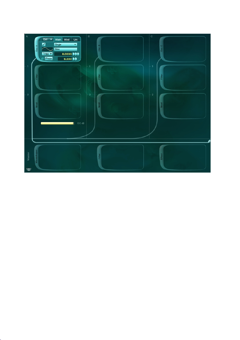
4.4. Patch Window
The Patch Window is the control center of ABSYNTH 4, where you assemble
the components that make up a sound. These components contribute to
producing and shaping the desired outcome. The modules represent the
individual components in the Patch Window. There are different types of
modules: Oscillator Modules are the sound sources of ABSYNTH 4. Modulation
Module, Filter Module and Waveshape Module shape the sound. In the following sections you will nd brief descriptions of the different Modules and
their features.
Absynth 4 – 45
Page 46

46 – Absynth 4
4.4.1. Signal ow
As you know from the introduction of this handbook, the design of ABSYNTH
4 is semi-modular. That means that you can determine the arrangement of
certain components yourself. Other components have a permanent place in
the Signal Flow.
Combine Modules
The Patch Window organizes the modules components into three Channels.
These Channels are designated with the letters A through C and they each
consist of three vertically arranged elds, the Module Slots. Each of these
Module Slots can be inserted with a Module. To turn a module on or off,
click on the extended frame on the left side of the module –where the writing
indicates the type of the module.
When inserting the modules, the following rules apply: The Module Slots A-C
of the three channels can only be loaded with an Oscillator Module. But the
remaining Module Slots, Module Slots 1 and 2, of any Channel can be loaded
with Modulation, Filter, or Waveshape Modules.
While the Oscillator Module always works as a signal source, the other
modules can shift between different types of operation: If you turn on a
module, then this module type will appear in the margin of the Module
Slot. Meanwhile the Type Popup Menu allows you to switch between
the operating Modes Filter, Mod and Waveshape. So, for example, you
can insert Filter Modules into both Slots of one channel, and insert into both Slots of one channel, and insertinto both Slots of one channel, and insert
two Waveshapers into another Channel.
Beneath Channels A, B, and C you can see three horizontal sliders, known as
the Channel Level Controls. With these sliders the levels of the three Channels
can be installed. ABSYNTH 4 can adjust the levels automatically so that the
sum of the three Audio Signals never exceeds 0 dB, even after a value in one
of the three Channels has been changed. To activate automatic volume levels
in the Stand-Alone Version, select Edit from the Main Menu and then the
entry Balance Levels from the Edit menu.
In addition, you can also use the Surround Pan Switch, which is located in the
lower left-hand corner of the Patch Window, to activate a mode that allows
you to position all three Channels in the Surround Panorama according to
your preference. This function can be used for impressive spatial effects, for
example, by modulating the Surround Position of the channels independently of
one another with an LFO or an envelope. More information about this is avail-
Page 47

able in section 4.10. The signals delivered by the three Oscillator Modules run
through the reactivated modules, and are mixed in the Master Channel under
the three Channels, which are arranged horizontally. After the Effect Module
in the lower right hand corner, the nished signal leaves ABSYNTH 4. The
lightly hued connection between the Modules makes this Signal Flow visible.
In the Master Channel, there is also a Module Slot reserved for a particular
Module: The Effect Module can always be found at the bottom-right of the
Patch Window and at the end of the Module chain. The other two Module Slots
in the Master Channel can be inserted with Modules of your choice.
Mono Mode and Poly Mode in the Master Channel
The modules in the Master Channel have two operating modes: Poly Mode
and Mono Mode. The difference between the two Modes can be heard particularly clearly in the Waveshape Module: In Poly Mode (three small arrows)
every voice has its own, independent Waveshaper. The distortion affects
every voice separately– in the same way as if every string on a guitar had its
own amplier. In Mono Mode (three arrows pointing toward one another) only
one Waveshaper is used for the different voices, which means that many of
the notes played interact – similar to the way that they do in chords played
on a distorted electric guitar. You can try out the effect simply by inserting
a Waveshape Module into the Master Channel. Play a couple of sounds now
and switch between both modes by clicking on the Mono/Poly Mode. You will
see that the Mono Mode reacts with signicantly stronger distortion as you as
begin to play multiple notes. This is because the signals of the different voices
are assembled before the Waveshaper input, which results in a higher input
gauge. In Poly Mode, by contrast, the voices are distributed among multiple
Waveshapers and thus produce lower signal levels.
Tip: In Mono Mode, the Waveshaper works with low input gauges like
a simple compressor and lends itself well to compressing and heating
up the lter input signal.
Absynth 4 – 47
Page 48

48 – Absynth 4
4.4.2. Oscillator Module
The three Oscillator Modules are the only stand-alone sound sources in
ABSYNTH 4. All of the other modules only function to change the sounds
produced by the Oscillator Modules. If none of the Oscillator Modules are
turned on, you will hear no sound, and none of the other Modules can be
activated. Accordingly, the Modules of a Channel are only available when
the Oscillator Module is active. The There are numerous different operating
modes to choose from the Oscillator Modules, which effect the synthesis
process. In the following sections, you will learn more about these individual
operating modes.
General Functions
Some control features are always displayed in the Oscillator Module indepen-
dently of the selected operating mode: the Edit Popup Menu, the Frequency
Popup Menu and the three Tabs Main, Mod, and Uni.
The Edit Popup Menu in the upper left-hand corner of the Oscillator Module
provides the following options:
• Copy Oscil copies the installations of the selected Oscillator Module to
the Clipboard.
• Copy Channel copies to the Clipboard the installations of all active
Modules of the selected Oscillator Module’s Channel.
• Paste Oscil places installations, previously copied o the Clipboard using
the command Copy Oscil, into the selected Oscillator Module.
• Paste Oscil and Envelopes places the installations, copied into the
Clipboard (with the command Copy Oscil), into the selected Oscillator
Module. Any envelopes linked to the Oscillator are also placed in the
Oscillator Module.
• Paste Channel places the installations of all of the active Modules of
a given Channel into the Channel.
• Load Oscil Template activates a Dialog, which allows you to choose
from a list of Templates with preinstalled Oscillator Modules (Universal
Library). Click on an entry in the list to choose a Template. Then click
OK to load the Template.
• Load Channel Template activates a dialog where you can choose from
a list of Templates with pre-congured Channels (Universal Library).
Click on an entry in the list to choose a Template. Then click on OK in
order to load the Template.
• Save Oscil as Template allows you to save the installations that you have
viewed in the Oscillator Module as Templates in the Universal Library.
Page 49

Choose this option to activate a Dialog where you can choose names
and saving locations for the Template. In this dialog, click OK to save
the Template.
• Save Channel as Template allows you to save the installations that
you have viewed in a Channel as Templates in the Universal Library.
Choose this option to activate a Dialog where you can choose names
and saving locations for the Template. In this dialog, click OK to save
the Template.
Universal Library
The Universal Library in ABSYNTH 4 makes it easier to bring together complex
sounds. Besides individual waveforms, envelopes and effects, you can save
and download complete modules with the appropriate envelopes as well as
entire Channels from the Universal Library. You will nd the library installation
folder of ABSYNTH 4 on the hard drive.
In the Patch Window you can save and activate Channels, Modules, and Effect
Presets together with all of the relevant envelopes. When you save a Channel,
a Module, or an Effect Preset as a Template in the Universal Library, the en-
velopes are automatically led with it. In order to load Templates, choose the
category you want from the Edit Popup Menu: In the Oscillator Module, select
the option Load Oscil Template in order to load a pre-congured Oscillator
Module. The command Load Channel Template allows you to choose from
all the completed Channels. In the Edit Popup Menus under Filter Module,
Modulation Module, and Waveshape Module you will nd the Load Template
option. ABSYNTH sorts the Library automatically for you: For example, you
cannot load a Filter Template into an Oscillator Module.
To save module installations or an entire Channel, choose Save Template in
the Edit Popup Menu of Filter Module, Modulation Module, and Waveshape
Module. In Oscillator Module, you can use the command Save Oscil as Template
or the command Save Channel as Template to save the entire Channel with
all of its modules and their installations.
The Patch Window is not the only location with access to the Universal Library.
In the Envelope Window and in the Wave Window you can also load and save
Templates. For example, you can store individual envelopes (separately from
their modules) and waveforms in the Library. In Envelope Window and in
Wave Window, you can access the Universal Library via the Transform Popup
Menu.
ABSYNTH 4 includes an extensive Library of Channels, Modules, Envelopes,
Effects, and Waveforms. To see how quickly the prefabricated channels from
Absynth 4 – 49
Page 50

50 – Absynth 4
the Library can build a complex Patch, simply click on the margin of an empty
Oscillator Module Slot in the Patch Window. It opens an Oscillator Module.
Choose the entry Load Channel Template for Edit Popup Menu on the upper
left-hand side in Oscillator Module. Once there, the list Channel Templates
will open immediately; choose the entry from Channel Templates whose name
you nd most to your liking. When you deal with the other two channels, you
will see how to create a sound in just a few seconds that could have taken
hours “by hand”.
Tabs
The Tabs allowing access to the bottom views Main, Mod, and Uni are also
present in the Oscillator Module (albeit occasionally inactive). Click on a Tab
in order to activate the appropriate view .
All of the parameters that deal with the Main Oscillator of an Oscillator Module
can be found under the Main Tab. The most important element in Main Tab is
the Synthesis Popup Menu, which allows you to perform the synthesis process
for the Main Oscillator. The synthesis processes that are available for selection from the Synthesis Popup Menu are sorted into three groups (separated
with a horizontal line).
• Wavetable Synthesis (Single Mode, Double Mode, FM Mode, Ringmod
Mode, Fractalize Mode, Sync Granular Mode): The Oscillator Module
produces Signals using monocyclic waveforms as the foundation.
• Sampling (Sample Mode, Granular Mode): The Oscillator Module
produces signals on the foundation of a sample.
• Externally produced Audio Signal (Audio In Mode): The Oscillator Module
delivers an Audio Signal, which itself comes from an external source
to the Module.
We will now examine the operating modes of the three synthesis processes
and their individual parameters in greater detail.
All parameters of the Modulation Oscillator (Mod Oscillator) can be accessed
via the Mod Tab. The parameters that you can access depends on which op-
erating mode is selected in the Main Tab for the Main Oscillator. Information
about these specialized parameters can be found in the sections on individual
operating modes.
In the operating modes Single, Double, FM, Ringmod, and Fractalize, the Uni
Tab allows you to choose from the following Parameters:
• num voices establishes the number of voices produced by the notes
played. The highest value is 8.
Page 51

• trans controls the degree of detuning in half-tones (which can only be
selected if the value selected under num voices is larger than 1).
• rand trans limits the permitted quota of accidental detuning (upwards
or downwards) in half-tones.
You can select the function Unisono in order to “stack” voices quickly and
produce fuller, stronger sounds. If you raise the value installed under num
voices by one, a new voice will be added and mixed with the output signal of
the Oscillator. The number in the Value Field trans determines what interval you
desire between the original sound and the tone pitch of the additional voices.
Even-numbered additional voices are transported downwards, odd-numbered
voices upwards. If, for example, you were to set the value for num voices at
3 and the value for trans at 1, every note would be accompanied by a voice
that has been transported deeper that sounds a half note higher. If you raise
the number of voices under num voices to 4, a new (even-numbered) voice
will be attached which is a half-tone under the last even-numbered voice (that
is, two half-tones under the basic tone). If you were to set the value for num
voices at 5, a new (odd-numbered) voice would be attached, which would be
one half-tone lower than the last odd-numbered voice. The Option rand trans
produces accidental detuning of the voices with every note in the sequence.
Subtly put to work, with a low value for num voices, rand trans can produce
the effect of a sloppy or imprecise intonation (in order, for example, to imitate
a string instrument without tension or to give atonal percussion sounds some
natural variation). You can get some unpredictable and exciting results by
playing around with different selections of notes— so have fun!
Tip: In the operating modes Sync Granular, Sample, Granular, and Audio
In the Unisono function is not available and the Uni Tab is inactive.
Waveform Popup Menu
In the Waveform Pop Menu, you choose the waveforms (Waveform, Wave) for
the Oscillators in ABSYNTH 4. This is not only the case for the Oscillators
Main and Mod in the Oscillator Module, but also for all of the other functions
in ABSYNTH 4 for which waveforms provide a foundation. You will also nd
the Waveform Popup Menu in an identical form in the LFO Window in the
LFO area of the Envelope Window. In contrast to the other Popup Menus in
ABSYNTH 4, the options in the Waveform Popup Menu do not appear as a
self-contained list, but rather are indicated in their own window due to the
limited space in the window.
Absynth 4 – 51
Page 52

52 – Absynth 4
This window, which you activate from the Waveform Popup Menu, essentially
contains a list of available waveforms. Using three buttons, you can switch
the list between three categories of Waveforms:
• Simples Waves are single cycle waveforms that are read from a
Wavetable. This relates to the tiny Samples that contain very precise
information about a period of a particular Waveform. In this rubric, you
also nd next to the standard forms Sine, Triangle, Saw, and Square
instrumental and atonal Waveforms.
• Morph Waves are Waves that use the function Wave Morph (see Section
4.6.5). From a technical point of view, Morph Waves are two waveforms
saved in one unit of data, which seamlessly blend (“morph”) with one
another.
• Library Waves are the Waves from the Universal Library of ABSYNTH 4.
In order to load the Waveforms of a particular category into the list, click on
the Button with the name of the desired Waveform category. You can load a
waveform into the Module by clicking on entryit in the list. The new Waveform
becomes immediately active, so that the effects on the sound can be heard
as soon as you push a button on your MIDI keyboard. The small waveform
display next to the Waveform Popup Menu also displays the new waveform
straightaway. When you have chosen a waveform, click OK on the place in
ABSYNTH 4 from which you activated the Waveform Popup Menu.
In order to produce a new Waveform, click on the Waveform Popup Menu on
the New Wave Button. A new waveform will be produced and loaded into the
Wave Window. ABSYNTH 4 switches the window display automatically to the
Wave Window. In the process, the selected Waveform is loaded as the template
for the new waveform. (Remember that your work does not affect the original
Wave, but rather produces an independent copy of it.)
If you want to work on a Waveform that already exists, click on the Edit Wave
Button. In this case, ABSYNTH 4 loads the selected waveform automatically
into the Wave Window and switches the display in an according fashion. You
can only work on Waveforms that you have already produced for this sound,
by clicking on the New Wave Buttons.
Frequency Popup Menu
The Oscillators from the groups of Modes of the different Wavetable synthesis
processes can be regulated in such a way that they react to the input of notes.
This process is known as Frequency Modes. Using the Frequency Popup Menu
in the Main Tab, you can choose the following Frequency Modes:
Page 53

• Trans: The Oscillator follows the tone of a played note in halftones. For
example inputting 1.5 in the Value Field Frequency Control corresponds
in this operating mode to transportation upwards by one whole and one
halftone. you can achieve changes to 1/1000 of a halftone.
• Ratio changes the Oscillator in a selectable frequency folder (for example
along the harmonic strip: “2” corresponds with a value of 12 halftones,
“3” with a transposition of 10 halftones, etc.). This mode is especially
useful when using frequency and ring modulation.
• Hz xed pitch in Hertz. In this mode, also useful for frequency and
ring modulation, the Oscillator ignores the pitch played. Rather, in this
Frequency Mode, the pitch of a tone reacts not to information like
Pitch Bend or to Signals from an LFO, but can be determined using
an envelope.
• Notes Fixed pitch that corresponds with a variable MIDI note. This mode
functions similarly to the Frequency Mode Hz, but is more appropriate
when you want to use the Oscillator on a note-bound frequency (e.g.
60.5 = C3 plus a quartertone).
Tip: You can switch between the Frequency Modes Hz and Notes to
determine the exact frequency of particular notes.
Anti-Alias Switch
The Anti Alias Switch enables you to remove sharp frequencies in the modes
for the Main and Mod Oscillator. Anti-Aliasing provides a smooth, almost
analogical sound. In order to turn on the Anti-Aliasing, click on the Anti-Alias
Switch – the small steps/ramp button in the upper left-hand corner of every
Oscillator Module. When the symbol displays “steps”, it means that the function
to smooth over of edges is off. A smooth line (“Ramp”) means that the function
is on for this Oscillator. This makes a big difference with high frequencies.
Without it, you would probably hear something called Foldback – a not-so
subtle form of digital distortion that makes high tones sound coarse or harsh
(two properties that are sometimes desired, but usually not ). Anti-Aliasing
reduces the Foldback to a large extent. Keep in mind that when an Oscillator
smoothes over edges, it uses more CPU power. If you can discern no difference between times when the smoothing over of edges is on and when it is
off, it would be best if you left it turned off. For reasons of compatibility, all
of the Patches equipped with ABSYNTH 1 are opened with Anti Alias Switch
deactivated. With ABSYNTH 4, you can create Patches, where for some
Channels the Anti Alias Switch is on, and for others it is not.
Absynth 4 – 53
Page 54

54 – Absynth 4
Single Mode
In the Single Mode a single Main Oscillator is active.
Under the Main Tab, you will nd all of the control features linked to the
Main Oscillator:
• Synthesis Popup Menu: To choose the desired synthesis process.
• Waveform Popup Menu: A click on the Waveform Popup Menu opens
a dialog where you can select the Waveform for the Oscillator.
• Anti-Alias Switch: Turns the Anti-Aliasing on and off.
• Frequency Popup Menu and Frequency Control: Enables you to enter
the Frequency as half pitches (Trans), as a relationship (Ratio), as a
Frequency (Hz) or through a MIDI note (Note).
• Phase Sync Switch: Setting the Phase Sync Switch to Sync will reset the
phase of the Oscillator with every incoming MIDI note. When the Phase
Sync Switch is set to Free, the Oscillator will not be reset. When only
one Oscillator is active and you have selected the number of voices in
the Uni Tab, Free mode has almost no effect. When you have a higher
Unisono number of voices or multiple active Oscillators, every note in
the change of the sound is audible.
• Phase Control: Sets the phase of the Oscillator. The effect is only
audible if a second Oscillator is active. This parameter is useful when
using integral frequency ratios between carrier and modulator, as is
the case in FM.
Double Mode
In Double Mode, a pair of Oscillators - consisting of the Main Oscillator and
the Mod Oscillator - is active. The signals of the two Oscillators are mixed.
Page 55

Under the Main Tab, you will nd the same Oscillators appear in the same
way as they do in Single Mode; more precise information can be found later
in the section Single.
The following parameters are available to the Mod Oscillator:
• Balance Control controls the balance of the Oscillators Main and Mod
within the Oscillator Module’s output signal.
• Waveform Popup Menu This opens a dialog where you can choose the
waveform for the Oscillator.
• Frequency Popup Menu and Frequency Control Using the Frequency
Control, you can enter the Frequency in halftones (Trans), as a relationship
(Ratio), as a Frequency (Hz) or through a MIDI note (Note).
• Phase Control: Here you set the phase of the Oscillator. The Effect can
only be heard when a second Oscillator is active. This parameter is
useful when dealing with frequency proportions, for example between
carrier and modulator in FM.
Tip: An Oscillator Module in the operating mode Double uses less CPU
power than two Oscillator Modules in single operating mode.
FM Mode
In FM Mode, the Mod Oscillator modulates the Frequency of the Main Oscillator.
Under the Main Tab you nd the same Parameters as in Single Mode; more de-
tailed information about this is available in the section Single. The Parameters
of the Mod Oscillator are:
• FM Index: This determines the depth of the Frequency Modulation
• Waveform Popup Menu: Clicking the Waveform Popup Menu allows you
to choose the waveform for the Oscillator.
• Frequency Popup Menu and Frequency Control: With the Frequency
Control you can enter the Frequency in half-tones (Trans), proportionally
(Ratio), as a Frequency (Hz) or with a MIDI note (Note).
• Phase Sync Switch: When you use the Phase Sync Switch in the position
Absynth 4 – 55
Page 56

56 – Absynth 4
Sync, the phase of the Oscillator is reset with every note-on-command
entered via MIDI. When the Phase Sync Switch is on Free, the Oscillator
is not reset. When only one Oscillator is active and the number of
voices in the Uni Tab is set at 1, the operating mode Free has almost
no effect. With additional Unisono numbers of voices or multiple active
Oscillators, the sound changes with every note.
• Phase Control: In Phase Control you determine the Phase of the
Oscillator. The Effect can only be heard when a second Oscillator
is active. This parameter is useful, for example, when balancing out
frequencies between carrier and modulator in FM.
Frequency modulation was discovered in the late 1960’s by John Chowning
and, achieved great popularity in the 1980’s through Yamaha’s DX7 synthesizer. Much has already been written about FM synthesis so we will not go
into detail here.
Ringmod Mode
In Ringmod Mode, the Signals from the Main Oscillator and the Mod Oscillator
are multiplied with one another. Under the Main Tab you nd the same parameters as in Single Mode; more precise information can be found in the
section Single. The Mod Oscillator has the following parameters:
• Balance Control controls the proportions of the two Oscillators, Main
and Mod, within the of the Oscillator Module’s output signal.
• Waveform Popup Menu: Click on the Waveform Popup Menu to open
a dialog where you can choose the waveform for the Oscillator.
• Frequency Popup Menu and Frequency Control With the Frequency
Control, you can enter the frequency in half-tones (Trans), as a
relationship (Ratio) as a Frequency (Hz) or with a MIDI note. For a
“classic” ring modulator sound, set the Oscillators either to Hz or
Note.
Page 57

Fractalize Mode
Experienced ABSYNTH users will recognize the Fractalize Mode as a real time
edition of the function Fractalize from the Waveform Editor of the Wave Window
(which also functions very similarly). In Fractalize Mode, the selected waveform
is copied to itself, so that you can see smaller elements of the waveform that
are similar to the image of the whole. You can use the Fractalize Mode to add
overtones to a plain waveform.
Under the Main Tab you nd the same parameters as in the Single Mode;
more precise information can be found in the section Single. The Mod Tab
provides access to the following parameters:
• Iterations: With this parameter you can choose the number of similar
repetitions that you want of the same sound, and how much you want
to deviate from the original waveform. The value area is between 1 and
8; higher values lead to more complex, lighter-sounding sounds – and
to a heavier CPU load.
• Amount: With this you can dene the mixing relationship between the
original waveform and the copies.
• Displacement: With this parameter you can dene the proportion that
the areas differ from the waveform: 0 corresponds to a position before
the waveform, 1 to a position after the waveform. With a value of
0.5, the area is directly central to the waveform. If you modulate this
parameter with an LFO or an envelope, interesting movements inside
the sound will result.
Tip: The function Fractalize in Wave Window gives you an idea of what
happens. Load a simple waveform, such as a sine, into the Wave Window.
Check under Wave View: so far nothing has happened. Choose the entry
Fractalize from the Transform Popup Menu. Set Iterations to value 2 and
Displacement to 9. Slowly increase the value for Displacement up to 25.
You see how the waveform distends. Change the value for Iterations; the
higher the value, the more dislocated the waveform becomes.
Absynth 4 – 57
Page 58

58 – Absynth 4
In Fractalize Mode under the Uni Tab you will nd a somewhat different com-
bination of parameters than in the Modes Single, Double, RM and Ringmod:
Transrans and rand trans work in exactly the same way as in the other Modes.
Instead of the Parameter num voices, the parameter Iterations operates a
similar function in setting the number of voices in Fractalize Mode.
Tip: Fractalize functions particularly well with Waveforms that contain
limited, yet strong harmonics: you will see new overtones emerge around
the basic harmonics. By choosing the right Waveform you can achieve
interesting, formant-style effects. With harmonically dense waveforms
(e.g. saw from the ABSYNTH 4 Waveform Library) the effect is not as
striking.
Sync Granular Mode
The Sync Granular Mode works along the same lines as the Granular Mode
(also the section Granular Mode for more): It divides a waveform into the
smallest parts (Grains) and then brings these parts back together. The difference between the granular synthesis processes in ABSYNTH 4 relates to
used output material: In Granular Mode, the Grains are taken from a Sample,
whilst Sync Granular Mode uses a waveform from the Library. In Sync Granular
Mode, you can take your own waveforms or an existing waveform from the
library, tear it apart, and then put it back together again in a new way. Before
putting the Grains back together through a process known as resynthesis,
you can inuence the Grain “cloud”: You can change the frequency of the
grains, change the value in Density Control to determine how individual Grains
overlap, and use the parameter Scatter to manipulate the level of diffusion of
the Grain cloud. These options allow you to create very effective sounds and,
for example, convincingly simulate the blowing sound of a wind instrument
such as a pipe or ute.
Under the Main Tab you nd that Sync Granular Mode has the same parameters
as in the Single Mode; more precise information can be found in the section
Single. The following parameters can be accessed through the Mod Tab:
Page 59

• Balance: Here you set the mix relationship between the original
Waveform and the Waveform produced by resynthesis. With a value ofWith a value of
0 only the original Waveform can be heard, with a value of 1 only the
resynthesized Waveform.
• Dens: Here you dene the density of the Grain cloud by setting a value
for how individual grains overlap. The values ranges from 3 to 8; small
values give a raw sound.
• Scatter: With this you can control the diffusion, that is, the accidental
scattering of the Grain cloud.
• Frequency Popup Menu and Frequency Control: With the Frequency
Control, you can enter the frequency in half-tones (Trans), proportionally
(Ratio), as a Frequency or with an MIDI note (Note).
Sample Mode
The Oscillator Module rules two sampling-based Modes: Sample and Granular.
These modes make it possible for you to use ABSYNTH as a Sampler, playing
back previously uploaded sound data in the WAV or AIFF format. The basic
control is the same in both modes, so the following instructions on the Sample
Mode also apply to Granular Mode.
In contrast to conventional Sampling instruments, ABSYNTH lacks the usual
functions such as Key Mapping, Velocity Layering, and AKAI import. Unlike
the conventional samplers, ABSYNTH’s emphasis is not on the realistic reproduction of sampled instruments, but rather the creative possibilities that
sample-supported synthesis provides. All three Oscillator Modules can load a
Sample; in a single Preset you can use up to three different samples.
Tip: Before you experiment with ABSYNTH’s sampling possibilities, you
should rst load a neutral patch. Choose the New Preset option in the
File Menu of the Navigation Bar, and then open the Patch Window.
In order to load a Sample into an Oscillator Module, choose the Sample op-
tion from the Mode Popup Menu. On the Waveform Popup Menu you will see
‘(none)’ displayed.
Absynth 4 – 59
Page 60

60 – Absynth 4
Then click on the Waveform Popup Menu. This activates a dialog that allows
you to open a Sample. Choose a Sample that you would like to load. Click on
Open. The Sample is loaded, and the Waveform Popup Menu indicates the
names of the loaded Samples.
ABSYNTH 4 can read AIFF and WAV data (stereo or mono) ranging from 16
to 32 bit and any Sampling rate. Stereo samples can be reproduced in stereo
or mono, depending on your choice. On the left of the waveform Popup Menu,
you can see the Mono/Stereo Switch. If you have loaded a Stereo-Sample,
you can use the Mono/Stereo Switch to shift between mono and stereo reproduction. If your Sample cannot be converted to Stereo, then it becames
a Mono-Sample.
In Sample Mode, the Main Tab allows you to change the following parameters:
• Frequency Popup Menu and Frequency Control: With Frequency Control
you can enter the Frequency in half-tones (Trans), proportionally, as a
Frequency (Hz), or using an MIDI note. The Sample will be reproduced
with its original speed when the MIDI Note C3 is played. Lower Notes
produce a slower, lower sound, while higher notes sound higher and
faster.
• Start Control establishes to what percentage each Sample plays in
relation to the total amount of time.
The following options can be reached via the Mod Tab:
• No Loop: The Sample is played once (good for percussion sounds).
• Loop All: The entire sample is played as a loop. This works best if you
edit the loop beforehand to create a seamless loop.
• Loop Edit: Two additional parameters are available if you choose Loop
Edit: Loopstart is the start point, Loopend the end point of a loop.
Granular
A Sample is fundamental to sound creation in Granular mode. However,
ABSYNTH 4 divides the Sample into many small Grains, each containing a tiny
fragment of the sound. In this way you can independently control pitch and
time within the Sample. In Granular mode, the duration of a Sample remains
Page 61

the same over the entire keyboard, whilst the notes determine the pitch. You
can choose from the following options under the Mod Tab:
• Time % determines the playing speed of the Sample. 50% corresponds
to half of the original speed while 200% doubles the speed of your
sound. If you set this value to zero, the Sample for that length of time
will “freeze”. When you have frozen a Sample, you can use the Parameter
Sample Start to establish when exactly it should freeze.
• Dens determines the number of Grains played simultaneously. Here
you can set values between 1 and 8. A lower value produces a thinner
sound, whereas a value of 8 or 9 produces a dense Granular “cloud”.
Remember: Big dens values use a lot of CPU power.
• Size determines the length of every Grain (in Samples). Smaller values
are good for percussive sounds, whereas higher values function well for
pad-like sounds or string instruments. Bear in mind that small values
tend to conceal the character of the Sample and produce typical granular
artifacts in the form of noise. The maximum value for the Parameter
is 9,999 samples (approximately 225 milliseconds at a sampling rate
of 44.1 kHz).
• R Time establishes how often the Grains are played randomly. 0
corresponds to no randomness during grain playback, whilst 100 means
that the grains are played completely at random.
• R Freq changes the pitch of individual Grains randomly. 0 means no
randomness, whereas 100 assumes complete randomness concerning
pitch.
• R Amp controls the amplitude (“loudness”) of the individual Grains
played at random. 0 equals “no randomness,” whilst 100 means
complete randomness.
Audio In
In the operating mode Audio In, an Oscillator Module does not produce a
signal itself, but rather receives and then treats audio signals from elsewhere,
as its own output. That makes it possible for any audio signal to work with
Absynth 4 – 61
Page 62

62 – Absynth 4
the other modules in ABSYNTH 4 in real time. ABSYNTH 4 can thus be
used as an effects instrument and work with live audio signals being played
elsewhere. You can also load ABSYNTH 4 as an Effect-Plug-In in its Audio
MIDI Sequencer and insert any traces of audio. When you have established
a Preset, in which Oscillator Modules work in the Audio in Mode, you should
attach this Preset to the Attribute Effect so that the Preset in Browser Window
reacts to the right search instructions.
You can access all of the Audio In parameters through the Main Tab:
• In: Choose from one of six possible audio inputs, which you can choose
by selecting the Audio and MIDI Setup option under the Stand Alone
Menu in the Stand-Alone version of ABSYNTH 4. .
• Db: strengthens or weakens the input signal. At the standard value
of 0 db, the Signal passes through the entry level unchanged. As in
Sampling-operating mode, by operating the Mono/Stereo Toggle (Ring/Double-ring symbol) you can choose between Mono- and Stereo signals.
If you choose Mono, you will only see one Popup Menu. If you choose
Stereo, then a second, identical In Popup Menu appears below the
rst.
Tip: External audio signals run through ABSYNTH’s signal path in exactly
the same way as internally created signals and so are also inuenced by
ABSYNTH’s envelopes. This means that you do not hear audio signals
from external sources unless ABSYNTH 4 has received MIDI notes
and used them to trigger the envelopes!
4.4.3. Filter Module
The Filter Module provides a number of Filters to work with. You can work
on the frequency spectrum of a sound and, for example, emphasize the high
frequencies while reducing the lower frequencies.
General Functioning
Turn on the Filter Module by clicking the extended left margin on a Module
Slot. Choose the Filter option from the Type Popup Menu. In the Popup Menu
Mode, you can choose one of the lter types below:
Page 63

Lowpass
Lowpass Filter LPF 2 pole
In the Lowpass section you can nd the Lowpass Filter, which weakens the
signal above an adjustable Cutoff Frequency. The slope gradient of a lter,
which dampens a signal, is given in dB per octave. A value of -12 dB /octave
means that the lter dampens the signal by 12 dB. Other values for slope
gradient are -6, -18, and -24.
The slope gradient is often referred to as the n-pole with relation to synthesiz
ers and other electronic sound producers,. On most occasions, n stands for
an even number between 1 and 8. This data can be easily translated into the
dB/Octave schema if you remember that every lter pole corresponds to a
steepness of -6 dB/Octaves. So a 1-pole Filter has a gradient of -6 dB/Octave,
a 2-pole Filter dampens the signal by -12 dB/Octave, and so on. ABSYNTH’s
Lowpass lter LPF 2 pole and LPF -12dB have the same gradient as the LPF
4 pole and LPF -24dB. Yet they sound different because of their different
internal constructions: The rst three lters in the list below have a softer,
rounder character, whereas the lters in the second group sound rougher and
more aggressive.
The following Lowpass Filters are available in ABSYNTH 4:
• LPF 2 pole, 2-pole lowpass lter with resonance controls with an analog
design.
• LPF 4 pole, 4-pole lowpass lter with resonance controls with an analog
design.
• LPF 8 pole, 8-pole lowpass lter with resonance controls with an analog
design.
• LPF -6dB 1 pole lowpass lter with resonance controls
• LPF -12dB 2-pole lowpass lter with resonance controls
• LPF -24dB 4-pole lowpass lter with resonance
All of the Lowpass lters in ABSYNTH 4 contain the following parameters:
Frequency Control allows you to enter the cut-off frequency in half-tones (Trans)
or as Frequency (Hz). You can set the resonance through the Resonance and
-
Absynth 4 – 63
Page 64

64 – Absynth 4
Control (Res). With the Damping Control (in dB) you can balance out the
volume level. If the signal level at the lter output seems too weak, increase
the value.
Bandpass
Bandpass Filter BPF
Bandpass lters combine Highpass and Lowpass lters: They dampen all
frequencies that lie outside a frequency range, which is dened by two cut-off
frequencies. This means a particular frequency range is allowed to pass through,
whilst lower and higher frequencies outside the range are suppressed.
ABSYNTH’s Bandpass Filter BPF has the following parameters: Using the
Frequency Control, the middle frequency is given in halftones (Trans) or as
Frequency (Hz). With the Q Control, the limits on the bandwidth of the lter
are established between 0.2 Hz and 1000 Hz.
Highpass
Highpasslter HPF –6dB
Highpass Filters permit all frequencies above a cut-off frequency and suppress the frequencies below it. Their remaining functions are identical to those
described in the section on “Lowpass.”
• HPF -6dB 1 Pole Highpass Filter
• HPF -12dB 2-Pole Highpass Filter with resonance controls
Using the Frequency Control you can give the cut-off frequency in halftones
(Trans) or as Frequency (Hz).
Page 65

Highpass Filter HPF –12dB
The lter variant HPF -12dB provides the Resonance Control (Res) the ad-
ditional possibility of adjusting the resonance.
Allpass
Allpass Filter Allpass 4
Allpass Filters, like ABSYNTH’s Filters Allpass 2, Allpass 4, and Allpass 8
allow all frequencies through the output with equal strength, but reverse the
phase of the signal. Allpass Filters allow you to be creative, as they can easily
produce Phasing or Resonance effects. With Allpass Filters, the number of
poles dene the number of peaks in the frequency spectrum of the ltered
signal. With high resonance values, an 8-pole Allpass Filter can sound very
similar to a glockenspiel.
ABSYNTH 4 offers three Variants of Allpass Filters to choose from:
All Pass 2 2-pole Allpass Filter
All Pass 4 4-pole Allpass Filter
All Pass 8 8-pole Allpass Filter
Every Allpass variant shares the following two Parameters: Frequency Control
allows you to choose the Cut-Off frequency in half-tones (Trans) or as Frequency
(Hz). The Resonance Control (Res) allows you to insert the Resonance.
Absynth 4 – 65
Page 66

66 – Absynth 4
Notch
Band Elimination Filter Notch
Notch is a band rejection lter with resonance. Band Elimination lters work
in the opposite fashion as Bandpass Filters: They only weaken frequencies
within a particular frequency range, established by two cut off frequencies.
Higher and lower frequencies can pass through unhindered.
Notch offers access to several Parameters. Using Frequency Control you can
set the cutoff frequency in halftones (Trans) or as a Frequency (Hz). Use
Resonance Control (Res) to set the resonance. With the Bandwidth ControlWith the Bandwidth Control
(b-width) you can set the width of the suppressed bands in octaves.
Comb
Comb Filter
Comb Filters like ABSYNTH’s Filter Comb change the sound by delaying the
signal by a few milliseconds and then mixing the delayed signal with the original.
Certain tones may increase in volume or be cancelled out as a result. Effects
such as the Phaser and the Flanger use this phenomenon. With the Comb
Filter, you can produce a Flanging Effect by modulating your parameters.
The Comb has the following parameters: With the Frequency Control you can
set the cut-off frequency in halftones (Trans) or as Frequency (Hz). Feedback
Control sets the level of the reverted, delayed signal and therefore denes to
what extent a signal increases in volume or is cancelled out. With the option
Damping Control (in dB), you can balance out any volume level uctuations
caused by the lter.
Page 67

4.4.4. Modulation Module
The Modulation Module uses its own built-in Oscillator in order to change and
modulate incoming Signals.
General Function
As with the Oscillators in the Oscillator Module, use the Waveform Popup Menu
to select or produce a Waveform. The Oscillator of the Modulation Module never
produces an audible signal on its own – what you hear is the result of interaction between input Signal and the Oscillator of the Modulation Module.
Ringmod
The function Ringmod produces Ring modulation and is very similar to the
Ringmod Mode of the Oscillator Module. The amplitude of the incoming Signal
and the Signal produced by the Mod Oscillator are multiplied with one another.
In Ringmod Mode the Modulation Module contains the following elements:
• Waveform Popup Menu: Click on the Waveform Popup Menu to open
a Dialogue and select the Waveform for the Oscillator.
• Frequency Popup Menu and Frequency Control: Here you can dene
the frequency of the ring modulators. You can choose between different
units (Hertz, Pitch, etc.) to change the Frequency.
• Balance Control: This control balances the incoming original signal and
the modulated Signal.
Frequency Shift
In Frequency Shift Mode the Modulation Module produces a frequency shift.
This resembles the frequency shift of the ring modulation, and it can also
bring similar sonic results. From a technical point of view, there is the following difference: While a Ring Modulator produces sum as well as difference
frequencies, the Frequency Shifter limits itself either to sum or difference
frequencies. Practically, this means that the operating mode Freq Shift pro-
duces subtler, better to control effects than the operating mode Ringmod.
The Parameters in Frequency Shift Mode are:
• Direction Switch: If this button is on “+”, it produces Frequency Shift
Control: Sum frequencies. If the button is on “-”the Module will produce
difference frequencies.
• Waveform Popup Menu: Click on the Waveform Popup Menu to open
a dialog where you can choose the waveform for the Oscillator.
Absynth 4 – 67
Page 68

68 – Absynth 4
• Frequency Popup Menu and Frequency Control: Here you can dene the
frequency of the modulator that is responsible for the shift in frequency
of the input Signal. You can choose different units (Hertz, Pitch, etc.)
to change the frequency.
• Feedback: Light dissonance (relative to the input frequency with low
Feedback can cause a steadily rising or falling Phasing effect. Very low
frequency settings (e.g., 1 Hz) can lead to similar effects.
Because there is no interference between sum and difference frequencies,
Freq Shift frequently sounds cleaner than Ringmod in situations involving
complex input signals (e.g. Samples, saw tooth waveforms).
Tip: Frequency shifting is not the same as Pitch Shifting. In Pitch
Shifting the Pitch Shifter multiplies the frequencies contained in a
Signal by a known factor, as a result, harmonious relations between the
frequencies remain. A frequency shifter, by contrast, attaches a known
value to the frequencies contained within a signal and thus alters the
harmonious relations.
4.4.5. Waveshape Module
The Waveshape Module uses a waveform to form an input signal. This idea
is used in guitar ampliers and distortion effects. Waveshaping reacts to the
amplitude of the input signal; the sound changes depending on the volume
envelope of the Oscillator or an Oscillator-Volume controller in some other
form. Additionally, waveshaping emphasizes Phasing and Detuning Effects
in the Signal.
General Function
You can always use the Waveshape Module when you want to enrich a signal
with harmonics. The spectrum goes from subtle density to cutting distortion.
The waveshaper reacts to changes in the amplitude. The level of distortion
changes with every uctuation of the input signal so the effect sounds very
energetic. The value can be modulated in Phase Control.
Parameters
• Waveform Popup Menu: With a click on the Waveform Popup Menu open
a dialog in which you can choose the waveform for the Oscillator. The
selected waveform denes the character of the distortion. Produce a
new waveform for the wave shaping and work on it in Spectrum Mode,
Page 69

in the Wave Window, in order to make yourself more comfortable with
the effect of the module.
• In dB Control: Denes the input level of the waveshaper in decibels. An
increase in value usually strengthens the distortion. This strengthening
is not linear, however, and depends on the selected waveform and the
value in Phase Control – experiment on an individual basis with the
different settings to get the sound you want.
• Out dB Control: Denes the output level of the waveshaper in decibels.
Here you can reduce the level of a signal when the waveshaper makes
it very loud.
• Phase sets the phase of the waveform. This parameter has an extreme
effect on the sound especially when working with complex waveforms.
These react very sensitively to any manipulation of Phase.
4.5. Effect Window Window
In the Effect Window you can manipulate all of the settings for ABSYNTH 4
effects: Here you nd the switch allowing you to assemble the Effect-section
in the signal ow. You can further determine which effect should be applied
to the signal produced by the Oscillator Modules. The individual parameter
settings can be determined here as well. The Input-Mixer allows you to adjust
the level of the Patch Window’s individual channels. On the output side, the
Effect Window informs you on the currently selected Surround Conguration.
Lastly, it also allows you to establish a link between the effects and the
ABSYNTH 4 functions for automation and control.
Absynth 4 – 69
Page 70

70 – Absynth 4
4.5.1. General Interaction
The Effect Window is divided into several sections: on top you nd the ele-
ments for using the basic functions, e.g. the On/Off button for the entire Effect
section and the Input Mixer. In the lower Master section you have access to
the different parameters, which allow you to regulate the active effect’s main
parameters. In the case of the effect called Echoes, we have the maximum
delay time. The lower section features the special parameters allowing a more
differentiated intervention into the sound event, such as the delay times for
the single delay lines of an echo-effect.
Change of Status and Selecting an Effect
The Effect Section On/Off Switch turns the Effect section on and off. If you
use a simple sound without effects, you can reduce the CPU load caused by
ABSYNTH 4. To turn the Effect section on or off, click on the colored eld
labeled Effect (directly underneath the Navigation Bar’s File Popup Menu).
If you turn the Effect Module in the Patch Window on or off, it has the same
effect on the operating status of the Effect Window.
In the same section you nd the Effect Mode Selector, a list of ve available
types of effects. To choose an Effect mode, click on the name of the desired
effect. Only one effect can be active at any given time. In the list, the currently
active effect mode is marked by a status light and is highlighted. Each newly
selected effect is reected in the lower section of the Effect Window, where
the individual parameters of the selected effect are indicated.
Signal Pathway
The Input Mixer on the right next to the Effect Mode Selector controls the
level of the signals produced by the oscillators in the Patch Window. The Patch
Window is, as you know, divided into three Channels and a Master Channel.
Usually the Effect Module always occupies the last place in the Master Channel
and is hence the last module in the signal path for the three Channels A, B
and C. Additionally or alternatively you can also feed the signals from Channels
A, B and C directly into the Effect Module. The individual Channels’ and the
Master Channel’s levels can be regulated with Input Mixer’s Channel Input
Level Controls. The levels of all four signals linked to the Input Mixer can be
modulated through Macro Control, creating a very lively sound – see also the
two sections below and chapter 4.9 of this manual.
If you select the signal-ow variant going through the Input Mixer, the signal
runs, after the mix, through two series of connected lters, which dene the
frequency bandwidth to be manipulated. A Lowpass rst denes the upper
Page 71

cut off frequency for the frequency band: all frequencies below the Cutoff
frequency selected in the Input Lowpass Frequency Control can pass through
freely. Subsequently a Highpass denes the cut off frequency at the lower
end, by only letting through frequencies lying above the Cutoff set in the Input
Highpass Frequency Control.
With its two Parameters Wet and Dry, the Input / Output Mixer controls the
level segments of the manipulated and not manipulated signal at the Effect
Module’s output signal: With the Wet Level Control you can regulate the part
of the effect-manipulated signal, with the Dry Level Control the part of the
not manipulated input signal.
In the Surround Area – the section with the central ring – you can see which
surround conguration has been selected for the hardware. Depending on the
number of active audio-output channels, the ring features up to eight points.
The arrangement of points corresponds to the selected channel conguration. Further details on the available surround congurations can be found
in Chapter 1.1.
Macro Control AreaControl Area Area
In the Control Area, on the right in the Effect Window’s upper section you
can select one of the Macro Controls and dene how the effect should react
to the arriving control information. You can regulate two parameters:You can regulate two parameters: Depth
Control ne-tunes the modulation depth, that is, the intensity affecting the
incoming control information. The depth of this modulation can be regulatedThe depth of this modulation can be regulated
through the several Sensitivity Controls, which will be described in the next
paragraph. TheThe Lag Control values determine the sluggishness with which the
effect parameters react to the control information.
You can use the Macro Control function to modulate certain parameters de-
pending on the effect type, for example the delay time in the types Multitap
and Echoes. Related details can be found in the following section.
You can assign the Parameters of each effect type in the Master section independently of special Parameters to a Macro Control. Right-click and select
the desired Macro Control from the context menu.
Absynth 4 – 71
Page 72

72 – Absynth 4
Modulation and Sensitivity Control
The Sensitivity Controls limit the signals received via Macro Control to a certain
value. With the Sensitivity Controls button marked Ctrl Sens, you can set the
percentage of a parameter value to be changed through the control signal.
This can be best explained through an example: In the case of the Effect Type
Echoes the settings could be:
• Master Time Control = 0.5 seconds
• Time Control Echo 1 = 0.5
• Sensitivity Control Echo 1 = 0,75
This has the following consequence: Echo 1 has a delay of 50% of the value of
half a second set in the Master Time Control, i.e. 0.25 seconds. The modula-
tion signal received through the Macro Control can change this value to 75%
(hence : 0.25*0.75 = 0.075 seconds, at a maximal signal value of 0.25%. If
you click on the Inversion Switch, the parameters act in exactly the opposite
fashion: a minimal value of the control signal sets the delay to 0.25 seconds,
the maximum signal value results in a delay of 0.075 seconds.
4.5.2. Pipe
The effect type Pipe replicates the physical qualities of resonating bodies
and resembles a simple waveguide application. Unlike waveguides based on
physical modelling, ABSYNTH’s pipe algorithm does not attempt to realistically simulate existing instruments or other natural resonating bodies. It is
helpful to imagine Pipe as a kind of string or pipe.
Let’s stay with the image of a string. A loudspeaker (a contact loudspeaker) is
connected to a string, which begins to vibrate as a result. You can determine
the position of this virtual loudspeaker on the string via the parameter Input
position. Above the string are two pickups, similar to an E-Guitar. The pickups’
positions can be determined through the parameter Output positions. Changing
Page 73

those two parameters can be compared with changing two microphones. You
can modulate the string’s length and the pickups’ position through the LFOs
or a MIDI Controller. This way, various Flanging-, Pitch-Shifting- und RotarySpeaker effects can be achieved. These effects are particularly apparent when
the modulation of the pickups are modulated in opposite directions.
When modulations are applied to the Parameters of the Pipe effect, consider
the following: When one of the Output positions crosses the Input position
(when loudspeaker and pickup would directly be facing each other) a mufed
side tone can be heard. By modulating the Parameter called Length, which
relates to the string’s length, the crossing values for Length and Input can
produce a mufed click. However, it is not a problem to cross the Output
positions. The graphic representation of the effect Pipe shows the current
settings of the parameters for Input position, Output position and Length, as
well as for the adjacent modulations. It should help you to prevent undesired
crossovers with the Input position.
Tip: LFO modulation in opposite directions of the output positions deliver interesting Panning effects. If the two points intersect, the sound
characteristics become mono..
Parameter
Parameter for the Master Section
• Beat Switch: With the Beat Switch you select, whether the value in
Time Control should be indicated in seconds, or tempo-related in beats
(quarter-notes) per minute.
• Master Length Control: determines the virtual string’s maximum length.
In terms of application this means: that’s where the maximal delay can
be set.
• Master Sensitivity Control: denes the Macro Control’s impact on the
value of the Master Length’s parameter in its percentage.
• Inversion Switch: If you turn on the Inversion Switch, the effect of the
control signal received via the Macro Control is inverted (see the section
on Modulation und Sensitivity Control)
• Master Feedback Control: determines the level of the feedback signal
in percentage of the original level; at higher values, the virtual string
resonates longer, at lower values it is silenced faster
• Lowpass Control: denes the cutoff-frequency of the Lowpass lter,
through which the feedback signal passes (in Hz). It changes the string’s
sustain characteristic.
Absynth 4 – 73
Page 74

74 – Absynth 4
Parameters for the Pipe Section:
• Input Position: Control denes the position for the element that animates
the virtual string to vibrate
• Output Position Control: L/R denes the position for the two pickups
L und R.
• Sensitivity Control: determines the impact of the control signal received
via the Macro Control on the value of the output position controls, i.e.
the position of the pickups in percent.
•
4.5.3. Multicomb
Der The effectThe effect Multicomb offers up to six independent Delay Lines, that are
based on comblters that use Lowpass lters in the feedback loop. Multicomb
specializes in modulation effects, and with the parallel series comblters and
an appropriate modulation source, you can easily achieve anging and other
effects based on phase shifts. For subtle to moderate phase modulations,
choose medium values. High feedback rates meanwhile, produce tuneable
resonance effects that sound like accords.
Parameter
The parameters in the Master Section are:
• Beat Switch: By selecting Beat Switch, you can determine whether the
value in Time Control is indicated in seconds, or is tempo-related and
measured in beats (quarter-notes) per minute.
• Master Time Control: determines the maximum delay of the feedback
signal, i.e. the comblter’s frequency. A high value results in a long
delay and thus a long vibration, i.e. a deep frequency.
• Master Feedback Control: denes the maximum level of the feedback
Page 75

signal, as a percentage value related to the original signal’s level. At high
levels, the comblter has a high resonance, and the sound’s overtones
produce a saw-tooth curve.
• Master Lowpass Control: determines the cut-off frequency of the
Lowpass lter, which is run through via the feedback signal (in Hz).
The parameters in the Comb Section are:
• On/Off Switch: allows each of the six comb lters to be turned on or off.
• Time Control: denes the frequency (and hence the delay time) of the
respective comb lter. This is measured in percentage, and correlates
to the value you have selected in the Master Time Control.
• Sensitivity Control: denes (as a percentage) how the Macro Control‘s
control signal affects the Time Control of the comb lter.
• Inversion Switch: If you turn on the Inversion Switch, you invert the effect
of the Macro Control’s control signal (see the section on Modulation
und Sensitivity Control)
• Feedback Control establishes the feedback signals’ level of every
individual lter as a percentage, which correlates to the value you
choose in the Master Feedback Control.
• Lowpass Control: controls the cut-off frequency of each Lowpass lter.
This is measured in percent, which again correlates to the value set
forth in the Master Lowpass Control.
• Gain Control: determines the level of each respective comb lter signal
at the output signal in dB.
• Pan Control: positions the signal of the respective comb lter within the
panorama of the output signal. The value 0 corresponds to the position
on the extreme left and 1 corresponds to the position on the extreme
right. 0.5 corresponds to the middle position.
Absynth 4 – 75
Page 76

76 – Absynth 4
4.5.4. Multitap
Multitap is a simple delay with three taps. The delays vary from one sampleThe delays vary from one sample
to 10 seconds. The input signal is delayed and transferred to the output according to the time set for the tap. This triples the transmitted signal.This triples the transmitted signal. Multitap
requires slightly more CPU power then Multicomb, but offers longer delay
times and more modulation options.
Interesting effects can be achieved by re-routing the delayed signal after the
rst tap back into the input. This way, dense delay clusters can be produced.
For the modulation sources of ABSYNTH 4, Multitap is an attractive option:
Try to shift the positions of the three taps during the tonal progression through
an envelope or an LFO. By setting the modulation source on the three taps’
Pan Controls and feeding the Effect Module with short, differentiated sounds,
the signals will move around in a more powerful way.
Parameter
Parameters in the Master Section:
• Beat Switch: With the Beat Switch you can choose whether the value in
Time Control is given in seconds or is tempo-related in beats (quarter
notes) per minute
• Master Time Control: determines the maximum delay of the three
taps
• Master Lowpass Control: determines the cut-off frequency of the lowpass
lter, which the feedback signal runs through (in Hz).
Parameters in the Tap Section:
• Time Control determines the delay of each respective tap in percent
of the value selected in the Time Control in the Master Section
• Sensitivity Control: denes the impact of the control signal received
via Macro Control of each tap’s Time Control (in percent).
Page 77

• Inversion Switch: Turning on the Inversion Switch inverts the impact
of the control signal received via Macro Control
• Gain Control denes the signal proportions for each tap at the output
in dB. For example, a value of –6dB reduces the level by half.
• Pan Control positions the respective comblter’s signal in the panorama
of the output signal. A 0 value corresponds to a position at the extreme
left, 1 to a position at the extreme right and 0.5 to the middle.
• Feedback Control: This parameter exists only for the rst Tap. It regulates
the level of the signal, which is re-routed to the input, as a percentage
of the original signal’s level.
4.5.5. Echoes
The Echoes effect type, as its name indicates, manages the classic echo-ef-
fects. The input signal can be delayed individually in up to three signal paths.
This means the signal for each active delay path runs successively through the
Lowpass, Highpass and Allpass lters. The three Panorama switches enable
the three delay paths’ output signals to be separated. The signal manipulation here is particularly interesting: the adjacent signal is directly routed to
the output (Parameter Gain). At the same time, it is sent back to the input of
the respective echo path by way of the Feedback function. An echo can lose
high and low frequencies when sent through a lter and thus sound duller or
more ethereal. The Allpass lter can produce phase shifts, which producesethereal. The Allpass lter can produce phase shifts, which produces. The Allpass lter can produce phase shifts, which produces
some interesting results, particularly using short delay times. These lter
parameters can also be modulated using the Macro Controls, which increases
the number of possibilities.
The user components in the Master section (Time, Feedback and Beat Switch)
function in the same way as the Multicomb effect. Each of the three delay
lines has the same set of parameters: Tie, Feedback, Sensitivity Control, Gain
and Pan, which work in the same way as their equivalents in the effect types as their equivalents in the effect types
Multicomb and Multitap. The allpass lter’s parameters in the Echoes effect
achieve the most striking results if modulated by an envelope.
Absynth 4 – 77
Page 78

78 – Absynth 4
Parameters
Parameters in the Master Section:
• Beat Switch: With the Beat Switch you can choose whether the value in
Time Control is given in seconds or in beats (quarter notes) per minute
• Master Time Control: determines the maximum delay of the three taps
• Master Feedback Control: denes the feedback intensity. Range:
0.0 to 0.999.
Parameters in the Echo Section:
• Time Control determines the delay of each echo (in percent) relative
to the value set in Time Control in the Master Section
• Sensitivity Control: changes the impact of the control signal (received
via Macro Control) on the echo’s Time Control (in percent), by the
value you set.
• Lowpass Control: determines the cut-off frequency of the Lowpass lter
that is applied to the signal in the feedback loop. The value in Lowpass
Control can range from 1.0 to 22050 Hz.
• Highpass Control: determines the cut-off frequency of the Highpass
lter that is applied to the signal in the feedback loop. The value in
Highpass Control can range from 1.0 to 22050 Hz.
• Allpass Control: determines the cut-off frequency of an Allpass lter,
which is similar to the Allpass 4 function in the Filter Module in the
Patch Window. Allpass lters let all frequencies pass through, but
change the signal’s phase depending on the lter frequency. The Allpass
lter produces its most impressive results when the parameters are
modulated, thus creating phasing effects.
• Gain Control: denes the output signal’s level of the respective echo
(in dB). A value of –6dB reduces the signal level by half.
• Pan Control: positions the respective echo signal in the panorama of
the output signal. A 0 value corresponds to a position at the extreme
left, 1 a position at the extreme right and 0.5 to the middle.
• Feedback Control: sets the level of an echo’s signal, which is routed
back to the input, as a percentage of the original signal’s level.
Page 79

4.5.6. Resonators
The effect type Resonators offers access to three “resonating bodies”
(Resonators). These Resonators can produce delay- and hall-effects, or simulate
the sound of specic objects such as metal bars, brake drums and bottles.
ABSYNTH 4 actually offers you three Resonators, which allows you to combine
many different effects. Imagine for example an almost innite hall-like effect,
accompanied by a shorter, brighter sounding Room effect.
Parameters
There are six Master parameters that affect all three resonators:
• Size Control: sets the maximum delay-length between 0% and 100%
• Feedback Control: controls the feedback quotient from: 0 to 100.
• Tone Control: controls the lters inside the resonators. The effect this
has depends on which feature is selected in the Mode Popup Menu
(see below).
• Drive Control: regulates the input’s recording level. This parameter
determines the input signal’s degree of saturation. If a high recording
level distorts the signal, the resonators react differently to when
stimulated by a clean signal. This is a very powerful setting, since it
also affects all other parameters.
• Predelay Control: sets the delay in milliseconds, before the onset of
the resonator-effect.
• Diffusion Control: creates random delay variations. A good adjustment
will reduce how much the resonator “rings” less, and higher values
make it sound grainier. Range: 0 to 100.
• ER Switch: turns the “early reections” on or off.
Additionally, each resonator has its own parameters:
Absynth 4 – 79
Page 80

80 – Absynth 4
• Mode Popup Menu: Select one of the following main features:
• Raw: dampened delay. The sound utters and is less diffuse
• Natural: more diffuse variation. Sounds rather dark.
• Resonant: more diffuse, brighter sound.
• Synthetic: like resonant, just more extreme. The parameter Tone Control
(see above) produces very different effects depending on which operating
mode you are using. Have an experiment with this parameter’s extreme
settings.
• Size Scale Control: The resonator size is the determined by the value
set by the Master-Parameter Size multiplied by the setting selected
under Size: Scale.
• Size Shape Control: allows you to adjust the various delay ratios. For
a hall effect, changing this value would be like changing the space
volume or -form.
• Size Ctl Control: adjusts the sensitivity of the parameter. Size reacts
to LFO or MIDI modulation commands. The Invert Switch inverts the
sensitivity.
• Tone Scale Control: The sounds created here are the result of a xed
Master Tone value multiplied by the setting selected in Tone Scale
Control.
• Tone Spread Control: Increasing the value of this produces a more
diffuse sound and also reduces feedback.
• Tone Ctl Control: Denes how sensitive the parameter Tone reacts to
LFO or MIDI modulation commands. The Invert Switch inverts the
sensitivity.
4.6. Wave Window
In the Wave Window you can manipulate your own waves with one of the
Waveform Popup Menus. As you may remember, Waveform Popup Menus
can be found in the Oscillator Modules, in the LFOs and in the Waveshaper
Module. Through them, you can select existing waves or create new ones.
They are divided into three categories:
• Simple Waves: are monocyclic waveforms, read from a wave table. In
principle, they are tiny samples containing exactly one period of the
relevant waveform. Next to the standard forms Sine, Triangle, Saw and
Square you can also nd atonal and instrument-like forms.
Page 81

• Morph Waves: are waves using the function Wave Morph (see section
4.6.5). Technically speaking they are two waveforms stored in one le
that have been “morphed” together.
• Library Waves: are the Factory-waves of the ABSYNTH 4 Universal
Library.
4.6.1. Waveform View, Spectrum View, Morph View
In the Wave Window, the tabs give you access to three views: Waveform View,
Spectrum View and Morph View. Click on one tab to access the work area
you want to view.
In the Waveform View you can edit the time component of a waveform, and
in the Spectrum View you can edit its harmonic component. In the Morph
View you can merge two waves into a Morph Wave. You can nd out more on
the Morph Wave in section 4.6.5. All the instruments that we will now lookAll the instruments that we will now look
at, work in real-time. You can play a sound, edit a waveform and hear the
results immediately.
4.6.2. Creating new Waves
To create a new wave, click on the Waveform Popup Menu in a module using
Waveforms. A window opens. First click on the button marked Single, Morph
and Library. This is where you can create a new Wave. Then click on the New
Wave Button. A new Wave is created. It is a copy of the waveform selected
in the Waveform Popup Menu. This allows you to quickly create variations of
already existing waveforms. Please note however, that this is in fact a new
waveform. It is completely independent for editing after being copied from
the original. To edit the original, select Edit Wave Button in the Waveform
Popup Menu. After a click on the New Wave Button, ABSYNTH 4 switches to
the Wave Window and displays in it the newly created Wave. Each Preset can
contain up to eight waveforms that you have created yourself. User-dened
waveforms are only available in the Preset where they were created. Other
Presets cannot access them. You can however easily manage them centrally
in ABSYNTH’s 4 Universal Library.
Absynth 4 – 81
Page 82

82 – Absynth 4
4.6.3. Editing Waves
In Waveform View you can edit the amplitude and the envelope of the waveform
on display. You can create your ownYou can create your own Waves completely from scratch using
different tools, or change existing Waves. In the section below you will learn
about the instruments and options available to you in the Waveform View.
Tools in the Waveform View
• Line Draw Tool: This tool allows you to build a waveform with straight
lines. The line starts at the point of origin, marked by a vertical bar
through the waveform display. On the time-axis displayed at the top t
of the window, you can move the point of origin with the mouse.
• Curve Draw Tool: constructs the waveform using semi-cosine curves.
This functions exactly like the Line Draw Tool.
• Stretch Tool: If you select this tool, two vertical lines appear at once.
Clicking on or dragging the wave with the mouse stretches or compresses
it within the lines. The squares can be moved along the time-axis to
select different areas.
• Amplication Control (dB): sets the wave’s amplitude (in dB)
• Offset Control: allows you set the amplitude’s offset in relation to the
zero-axis. A double-click on Offset Control centers the waveform around
the zero-line.
Page 83

Transform Popup Menu �Waveform View)Menu �Waveform View) �Waveform View)
• Normalize: normalizes the waveform’s amplitude: the current waveform’s
minimum and maximum values are adjusted to the maximum value
range. If you normalize each waveform you will always obtain the same
volume, no matter which waveform is selected.
• DC Offset: this function assures that the waveform’s energy will be
evenly distributed between its positive and negative sections. This is
different from centering the waveform through the Offset Control.
• Offset Phase…: allows you to programme a phase offset for the
waveform.
• Invert Phase: inverts the waveform’s phase.
• Reverse: reverses the waveform.
• Mix…: opens a window where you can mix the waveform with another
one, selected from the Waveform Popup Menu. The following parameters
are available in the Mix… Dialog:
• dB A: determines the level of an existing waveform.
• dB B: determines the level of the waveform to be mixed.
• Phase B: denes the phase position of the waveform to be mixed, in
relation to the existing waveform.
• Freq Ratio B: denes the frequency ratio between the waveforms.
Tip: You can use the parameter Freq Ratio B to produce accords based
on intervals of harmonic series. If you repeat the mixing procedure
several times with a different frequency setting, you will add new notes
to the accord.
• Fractalize…: The Fractalize function allows for extraordinary waveform
manipulations and is particularly good for creating powerful, organic
waveforms. The parameters are:
• Iterations Control: controls how detailed the waveform’s manipulation is.
• Displacement Control: changes the fractalized waveform’s basic shape.
• dB Control: controls the fractalization’s intensity – the higher the value,
the richer the sound in overtones and noise.
Absynth 4 – 83
Page 84

84 – Absynth 4
• Filter: applies a lter to the Wave. In the Filter Popup Menu you can
select one of the following lter types:
• Lowpass 1st order: is a Lowpass lter with a slope gradient of – 6 dB
per octave.
• Lowpass 2nd order: is a Lowpass lter with a slope gradient of – 12
dB per octave.
• Highpass: is a Highpass lter with a slope gradient of – 6db per octave.
• Frequency Control enables you to set the lter’s cut-off frequency.
Lowpass ltering of waveforms is the best way to prevent undesired
aliasing effects.
• FM: Frequency modulation; the current waveform serves as carrier. This
dialog allows you to change the following features:
• Waveform Popup Menu: select a modulator waveform from the Waveform
Popup Menu
• Modulator Frequency Control: denes the frequency ratio between
modulator and carrier.
• Modulation Index Control: determines the FM’s intensity.
• Carrier Frequency Control: denes the carrier’s frequency ratio
• Mod Phase Control: regulates the modulator’s phase.
• Load…: loads a waveform and replaces the existing waveform.
• Import from audio le…: loads the rst 1024 samples from an AIFF- or
WAV le as a waveform.
• Load Template…: retrieves a saved waveform from ABSYNTH’s
Universal Library.
• Save as Template …: saves a waveform in ABSYNTH’s Universal
Library.
• Clear: produces silence.
Page 85

4.6.4. Spectrum Edit
The Wave Display Area in Spectrum View displays the edited waveforms’ rst
64 harmonics. The top half of the display shows the harmonics’ amplitude, the
lower half their phase. At the bottom of the window you can see – depending
on the mouse position – the harmonic’s number as well as its amplitude and
phase. Harmonics above the 64th will be retained, although they can not be
accessed in Spectrum View.
Hint: Some might think that a harmonic’s phase is not perceptible, but this
is incorrect. Although the phase is less audible then the amplitude, a changehen the amplitude, a change
of a harmonic’s phase with a complex waveform can be clearly noticed in waveform can be clearly noticed in
the sound. In the following section you will learn about the tools and options
available in Spectrum View.
Tools in Spectrum View
• Single Harmonic Draw Tool: This tool enables you to draw different
amplitudes and phases for a harmonic. This can be used for precise
manipulations.
• Multi Harmonics Draw Tool: This tool enables you to draw the amplitudes
and phases for several harmonics at the same time.
Transform Popup Menu �Spectrum View)Popup Menu �Spectrum View) Menu �Spectrum View)
• Invert phase: inverts the phases of harmonics.
• Shift harmonics: shifts the entire form of the spectrum to the left or
to the right.
Absynth 4 – 85
Page 86

86 – Absynth 4
• Load…: loads a random waveform and replaces the existing
waveform.
• Load Template: opens a dialog and lets you select and load a Wave
from the Universal Library. Select the Wave you want to load. Click OK
to load the Wave into the Wave Editor.
• Save as Template: saves a waveform in ABSYNTH’s Universal
Library.
• Clear all: sets all amplitudes and phases to zero.
• Clear amplitude: sets all amplitudes to zero.
• Clear phase: sets all phases to zero.
4.6.5. Wave Morph
A new addition to ABSYNTH 4 is the Wave Morph function, which allows you
to “morph” two waveforms into one new Wave. The two Waves combined
in a Morph Wave remain completely independent however, and can still be
edited individually in the Wave Window. If you load a Morph Wave into an
Oscillator Module or into a similar module, the new waveform (created via
morphing) will be the one used. You can, of course, freely modulate the Wave
Morphing’s parameters. That way, you create lively, dynamic sounds that can
change subtly or even take on a completely new character while being played.
It’s up to you!
Loading a Morph Wave differs from loading a Simple Wave. First, you have
to enter Morph Wave as the Wave type in the Waveform Popup Menu. Click
on Morph Wave in the Waveform Selection Dialog. The list of Morph Waves
appears. When you click the New Wave Button, you create a new waveform
that uses the selected waveform as its model. As a result, the Morph Wave
is loaded into the Wave Window automatically. You have the same options
for editing the two waveforms as with Simple Waves (previous chapter): you you
can edit the simple waves in Waveform and in Spectrum View, and you can
switch between the two waveforms using the Wave 1 and Wave 2 buttons in
the tab bar. The distinguishing feature of the Simple Waves is in Morph View.
It determines how ABSYNTH merges both waveforms into a single one.
Click the Morph Tab, to show the Morph View. The Wave Display in this view
is divided horizontally into three sections: At the top you can see Wave 1, in
the middle Wave 2, and at the bottom the resulting Morph Wave.
Page 87

The morphing happens over two parallel processes, which are controlled by
Transition Control (between Wave 2 and Morph Wave). At a 0 value only Wave
1 will be used, at the value of 100 only wave 2 is active. In between, the
waveforms can be cross-faded, compressed and extended.
The rst step is quite simple – it is the usual method for mixing both waveforms: if the Transition Control is set at 50, exactly 50% of each original wave
is contained in the resulting Morph Wave.
Cross fading becomes more exible through the Anchor Points, and can be
used in various ways for designing waveforms. As you can see in the picture,
two vertical Anchor Points A and B divide the Wave in the upper sections
Wave 1 and Wave 2. Through these Anchor Points, you can determine the
segment of both waves: both waveforms are divided into segments A to B and
B to A. Please note, that the waveforms are single cycles of one continuous
vibration. The waveforms don’t end at the display’s left and right sides, but
are continued on the opposite side. That is how segment B to A is created.
During morphing, equivalent segments are put into correlation with each other,
i.e. segment A to B from Wave 1 with segment A to B in Wave 2.
This becomes important when you move the Anchor Points: click and drag
the Anchor on the upper end to move it. This allows correlated segments
to vary considerably in length. By adjusting the segment’s length with the
Transition Control, this change in length is now integrated into the morphing.
On a practical level, this means that at a value of 0, the wave quotient of the
segment between A and B from Wave 2 will be compressed or extended to
t the length of the corresponding segment of Wave 1, depending on aspect
ratio. Inversely, at a value of 100, the wave quotient between A and B from
Wave 1 will be stretched or compressed to t the segment length in Wave 2.
The same applies to the segment between B and A.
Absynth 4 – 87
Page 88

88 – Absynth 4
You can make these distortions even more exible, if you increase the number
of Anchor Points. In the Anchor Points Popup Menu you can select whether
you want two, three or four Anchor Points to appear in each of these waves,
allowing you to create more segments.
The effects of manipulating the waveform-segments are not as apparent as
you might assume after reading the section above - since the usual mix of
both waveforms takes place at the same time: if Wave 2 is compressed and
extended to a maximum, it is also simultaneously leveled down to 0% in
its resulting wave. Correspondingly Wave 1 is not present in the mix, if it is
manipulated by a Transition Control value of maximal 100.
The quick introduction in section 3.4.3 is also devoted to Wavemorph, and
the technical description is accompanied by illustrations of the resonating
result.
The switching of the anchor points has a useful effect on the resulting waveform; it makes morphing a subtle design tool. The modulation of Transition
Control through a Macro Control (see section 4.9.2) is particularly interesting.
You can, for example, switch easily between two very different waveforms
that you want to use as sound source in an oscillator. There are many more
possibilities than simply fading in and fading out. Both waveforms are mixed
in a non-linear way.
As another example, you can also use a Wavemorph in a Waveshape
Module.
The Waveshape Module reacts in a very sensitive way to jumps in the waveform
(such as those present in a square wave), Morphing enables you to achieve an
extensive sound variance by continuously stretching and compressing - i.e.
shifting and distorting those jumps.
Page 89

4.7. Envelope window
ABSYNTH 4 provides Envelopes with up to 68 Breakpoints for modulating
the parameters. These Envelopes are extremely exible and offer a variety of
extraordinary options.
4.7.1. Fundamentals for Operation
It is standard that every oscillator has an amplitude envelope. The amplitude
envelopes have a special status because they dene whether or not a voice
is calculated or not. As soon as all amplitude envelopes of one voice have
reached their last Breakpoint, the calculation is stopped, reducing the CPU
burden.
When an envelope modulates a parameter, the value set in the Patch-Window,
represents the maximal value of the envelope. The envelope can reduce this
value but cannot increase it. For example: If a lter that has a frequency of
5000 Hz is modulated by the envelope, then the envelope works between
the range of 5 Hz to 5000 Hz.
Zoom-Function
You can see the scales for amplitude and time on the top-left of the envelope
representation, marked by the magnifying glass icon. Move the mouse in
these zones to zoom in on the horizontal and vertical representation of the
envelopes. It is possible to zoom in on the time-axis to such a degree, that
one pixel corresponds to one sample.
Absynth 4 – 89
Page 90

90 – Absynth 4
Envelope List
The Envelope List contains all assigned Envelopes. Selected Envelopes are
displayed in the Envelope Display, while deselected ones are blanked out.
The names of the envelopes inform you about the module type (Oscil, Filter,
Mod), Channel (A, B, C, Master) and target parameter. To choose an envelope
for viewing in the Envelope Display, just click on it with the mouse. You can
select consecutive entries from the list by holding down the Shift key and
clicking on the highest envelope followed by the lowest. To select several
non-consecutive entries from the list, hold down the option-key (Mac OS) or
Ctrl-key (Windows).
The Envelope List has two menus::
• New Envelope Popup Menu: here you can create a new envelope.
Click on the New Envelope Popup Menu to open a window where you
can select a Parameter to create an envelope. Choose the Module by
clicking on the desired entries, rst in the left column, then on the
Parameter in the middle column. Only the relevant Parameters appear
in the Parameter List. For example, if an oscillator is working in Single
Mode, the parameter FM index is not displayed. If you switch the
oscillator to FM Mode, the Parameter is visible. You can see a preview
of the currently selected Envelopes below the three columns.
• Show Popup Menu: The Show Popup Menu offers a quick way to fade
in and fade out different groups of envelopes in the Envelope Display.
This way you can always keep an eye on the envelopes you want to see
at any given time, and do not have to constantly consult the scroll bar
Page 91

in the Envelope Display. Click on the Show Popup Menu to access a
list of following display options:
• All displays all Envelopes that are used in the current preset.
• None blanks out all Envelopes that are used in the current preset.
• Channel A displays all Envelopes that belong to the Modules in Channel
A of the current preset.
• Channel B displays all Envelopes that belong to the Modules in Channel
B of the current preset.
• Channel C displays all Envelopes that belong to the Modules in Channel
C of the current preset.
• Master Channel displays all Envelopes that belong to the Modules in
the Master Channel of the current preset.
• All Oscil displays all Envelopes that belong to the Oscillator Modules
of the current preset.
• All Filter displays all Envelopes that belong to the Filter Modules of the
current preset.
• All Mod displays all Envelopes that belong to the Modulation Modules
of the current preset.
• All Waveshape displays all Envelopes that belong to the Waveshape
Modules of the current preset.
• All Effect displays all Envelopes that belong to the Effect Window of
the current preset.
Selection of a Envelope
You can select an envelope for editing by clicking on the envelope image. The
name of the selected envelope is then highlighted.
Copying and Inserting of Envelopes
To copy an envelope, select the entry Copy Envelope in the Edit Menu.
Then click on the targeted envelope and choose Paste Envelope in the Edit
Menu.
4.7.2. Breakpoints, Transitions/Steps, Sync
The Breakpoints represent target points on the time axis and therefore affect
the previous gradient-segment. Click on a designated envelope to select it for
editing, and choose from the following features in the Selected Breakpoint
Area.
Absynth 4 – 91
Page 92

92 – Absynth 4
• Abs/BP Time Control: determines the duration (in position Bp sec) that
the parameter lasts before reaching the Breakpoint on the amplitude
value. Enter the duration in seconds. If you click on the Toggle that is
labeled with Bp sec, you can insert the duration as an absolute value
(based on the beginning of the Envelope).
• BP Amplitude Control: denes the amplitude for the selected Breakpoint.
You can either insert a value directly in dB (on a scale of 0 dB to –96dB)
or adjust a percentage with 0 dB as the relation point. To switch between
dB and %, click the BP Amplitude Toggle.
• Slope/Step Switch with Slope Control: With the Slope/Step Switch
you can inuence the transition between the previous Breakpoint in
the envelope path and the selected Breakpoint: The position Slope
represents the typical wave shape; with the value in Slope Control
you can determine the slope of the curve progression. In the position
Step, the change in value jumps, and instead of the curve you will see
a colorful rectangle between the previous and the selected Breakpoint.
Drag the rectangle upward, with the mouse button held down, to boost
the value in the specied division. Drag it downward to diminish the
value. You can also change the horizontal dilation (i.e. how long the
value lasts), by moving the Breakpoints, which mark the corners of the
Step-rectangle. Just hold down the mouse button.
These three parameters allow you to position the Breakpoint very precisely.
You can also move the Breakpoint with the mouse to determine its amplitude
and position directly. You can move several Breakpoints at the same time by
using the Shift-click or by clicking and drawing the selected area above the
part of the Envelope that contains the relevant Breakpoint. Every editing step
inuences all selected Breakpoints and the parameter amp, abs time and slope
as well as the MIDI and LFO-settings. The absolute time and the adjusted
parameter are displayed below Time Control and Amp Control.
Page 93

In the illustration above shows, the envelope modulates the lter 1 parameter.
For this reason the lter frequency is displayed in the parameter-division of
the selected Breakpoint. Slope determines the wave shape according to the
sequence of the Breakpoints. A value of 1 creates a linear progression, and
lower values create different exponential sequences.
Creating and Deleting Breakpoints
To create a Breakpoint simply hit a command-click (Mac) or a right-click
(Windows). To delete a Breakpoint, perform a Ctrl-click (Mac) or respectively
repeat the right-click (Windows).
Grid Switch
Click the Grid Switch to turn the grid in the envelope-representation on and
off. If the grid is turned on, then the Grid Popup Menu appears on the right
side next to the Grid Switch. Choose the favored resolution of the grid from
the Grid Popup Menu. The default value is 1/8 (the grid amplitude corresponds to **eight notes). Other possible resolutions are 1/16 (sixteen notes)
and 1/32 (thirty-two notes). If the grid is being displayed, the Breakpoints
automatically register on the lines. You can overwrite the registering by drawing the Breakpoints with a depressed Ctrl-key (Mac), respectively Alt-key
(Windows).
Lock/Slide Switch
With this you can determine how the Breakpoints react to movement with
the mouse: you can only move a Breakpoint to the next step of the grid if
Absynth 4 – 93
Page 94

94 – Absynth 4
you have chosen a Lock. The move does not affect the parts of the envelope
that follow the next Breakpoint. All of the following Breakpoints can also be
moved if Slide is selected.
Lock is especially useful for rhythmical envelopes, where the Breakpoints are
supposed to be synchronized with beats.
Free/Sync Switch
<image: Free Sync Switch
Apart from Control Driven Envelopes (which are independent of time}, you can
synchronize to the tempo of the Host-Software by switching the Free/Sync
Switch to Sync.
Sustain/Release Marker
The Sustain/Release Marker determines which Breakpoint represents the
Sustain/Release-point of the envelope. The exact function of the marker
depends which envelope mode you select (see below). With the exception of
the rst and last, you can drag the marker of every Breakpoint.
4.7.3. Envelope Modes
You can choose from several Envelope Modes, named Release, Sustain, Loop
und Retrigger, from the Envelope Mode Menu. A special case is the Control
Driven Envelope, which is controlled by MIDI. The envelope mode Sample
Jump also works in a different way to the other variations. We will deal with
that later together with the Link Mode, where two Envelopes can be connected
to one other.
Page 95

Release Mode
If you have chosen Release Mode and play a note, the envelope will run from
the beginning until the last Breakpoint. If you release the note before the
Sustain/Release-point is reached, the envelope jumps to the position of this
point and proceeds on its path from there until the end. The Release Mode
is advisable with percussive sounds and piano-like sounds with sustain. If the
Sustain/Release point placed near the beginning, the envelope always progresses in the same way, independent of the length of the releasing note.
Absynth 4 – 95
Page 96

96 – Absynth 4
Sustain Mode
In Sustain Mode the envelope works similarly to a classical ADSR-envelope. If
you have selected this mode and then play a note, the envelope will proceed
to the Sustain/Release point and its value will remain constant from then on.
If you release the note, the envelope runs through the remaining sequence to
the last Breakpoint. If the note is released before the Sustain/Release point
is reached, the envelope jumps to the position of this point and proceeds on
its path from there until the end.
Page 97

Loop Mode
If the Loop Mode is selected, a Loop Start Marker that looks like a sideways-
tilted U will be displayed together with the red Sustain/Release Marker. You
can use this Marker to select all the Breakpoints prior to the Sustain/Release
point, right up to the rst one. Segments of path inside the Loop are blue,
while segments outside are green. Consider that Breakpoints are target-points
of the path – therefore the segments of path prior to the Loop Point also belong
to the Loop. In Loop Mode, the envelope jumps to the Loop Start Marker as
soon as it has reached the Sustain/Release Marker, and repeats the section
in between until the note is released. The complete duration of the looped
section is the Delta-time of the Loop-starting-point.
Absynth 4 – 97
Page 98

98 – Absynth 4
Retrigger Mode
In Retrigger Mode, the envelope is restarted according to the Retrigger-value the envelope is restarted according to the Retrigger-value
when a note is held. If the note is released before the Sustain/Release point
is reached, the envelope jumps to the position of this point and proceeds
from there until the end. If the Sustain/Release Marker is located inside the
Retrigger Loop, the envelope keeps its position. The Release Mode is especially
useful for creating rhythmic, looped paths. You can feed the retrigger speed
as number of beats into the Retrigger: Beat Control.
Page 99

Control Driven Envelopes
Even though Control Driven Envelopes look like all of the other envelopes, the
way they function is signicantly different. Compared to normal envelopes, the
particularities of Control Driven Envelopes can be more readily understood:
While a normal envelope is controlled by time, in Control Driven Envelopes
Mode, a Macro Control allows movement on the X-axis. The MIDI-value 0
refers to the beginning of the envelope, 64 the middle, and 127 it’s the end.
If the minimal value and the maximal value are connected by a diagonal,
straight line, changing a signal value, which is assigned to a Macro Control
directly, will inuence the dedicated parameter. The incoming signal value
is translated into a change of parameter at a ratio of 1:1. If you draw a more
complex form with the Control Driven Envelope (and in doing so establish aand in doing so establish a
non-linear control type), things start to get interesting. You are now able to
morph between sounds, and even create Arpeggios by turning a controller and
using the modulation-wheel to control the speed of rhythms. There are many
examples of using Control Driven Envelopes in the Factory Presets. To create a
Control Driven Envelope yourself, select Control Driven in the Envelope Mode
Menu at the top of the envelope’s window that you would like to control via
MIDI. of the length of the Control Driven Envelope and the number of points
does not matter: The area that can be accessed by Macro Control ranges from
the very beginning to the very end of the wave.
Absynth 4 – 99
Page 100

100 – Absynth 4
Link Mode
All changes made to the Master Envelope have an immediate effect on sub-
ordinate Envelopes if you connect two or more via Link Mode. To create a
connected (subordinate) Envelope, select the Link in Mode Menu at the top
of the envelope’s window that you wish to connect. Even though you cannot
directly edit a subordinate Envelope, you can still assign certain characteristics
to it. You will notice that all changes will be reected in the visual representation of the connected Envelope. You choose the Master-Envelope under the
Source Popup Menu:
• Source Popup Menu: select the master-envelope
• Time % Control: scales the temporal progression of the subordinate
Envelope. 50% corresponds to double the speed of the Master Envelope,
200% half the speed.
• Amp % Control: scales the amplitude of the subordinate Envelope.
• Amp Offset Control: boosts or diminishes the zero-line of the subordinate
Envelope.
• Slope % Control: scales the escalation of the subordinate Envelope.
The Link Mode not only saves you time when editing similar Envelopes, but
serves for creative purposes as well. You could, for example, alter the Cut-off
 Loading...