


nat 01
NAIM nat 01, nat 02, nat 05, headline, stageline Manual
...
OWNERS MANUAL
Connection Guide

c
contents
cd players
2 cds
4 cdx
6 cd5
tuners
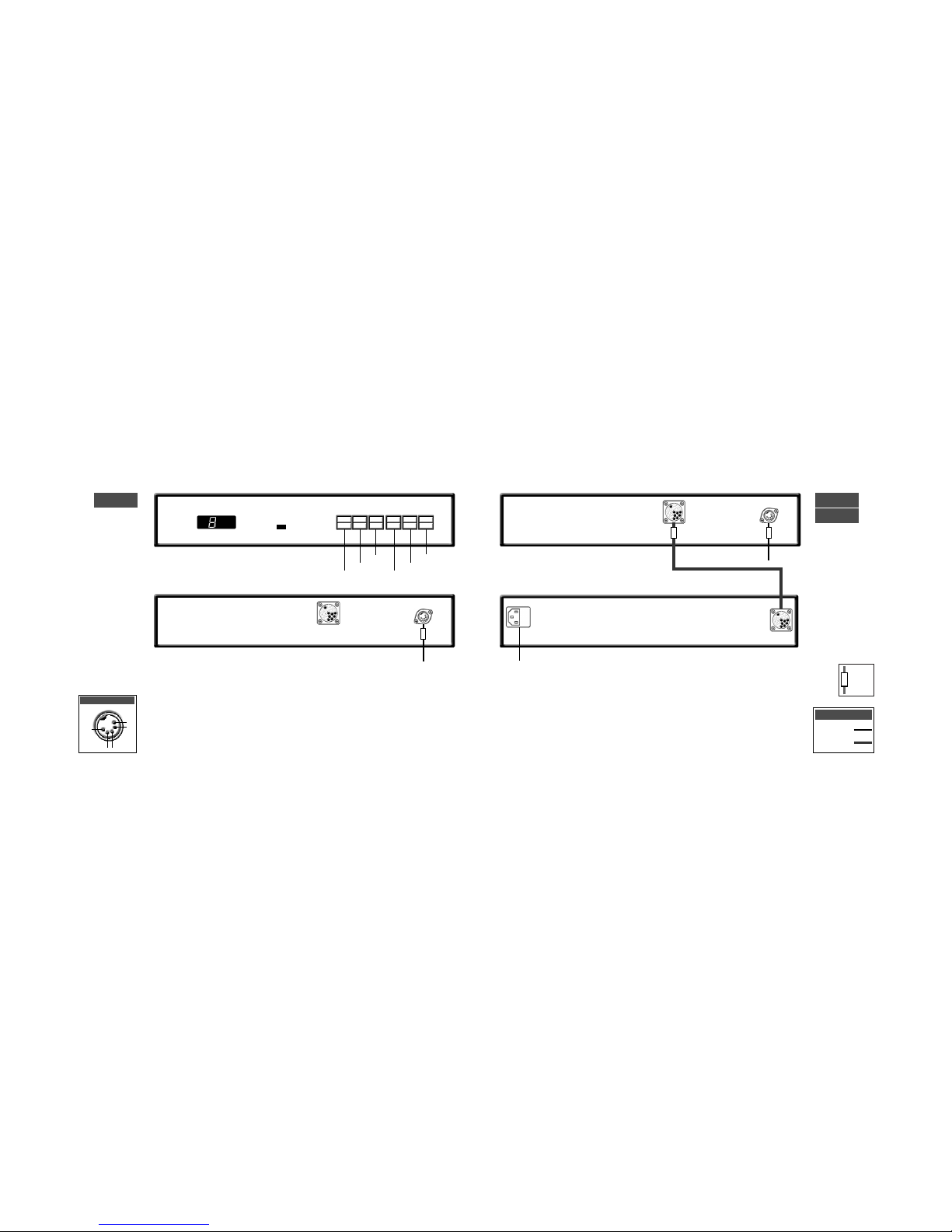
8 nat 01
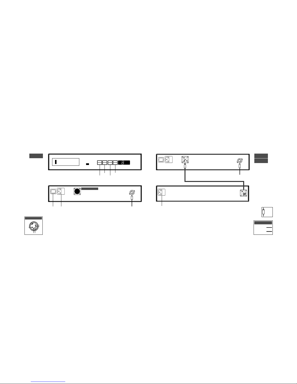
9 nat 02
9 nat 05
headphones
10 headline
phono stage
11 stageline
preamplifiers
12 nac 52
14 nac 82
18 nac 102
20 nac 112
a/v processor
22 av2
integrated amplifier
24 nait 5
power amplifiers
28 nap 500
29 nap 135
30 nap 250, nap 180, nap 150
31 nap 140, nap 6-50, nap v175
power supplies
32 supercap, hi-cap
33 flatcap 2
active crossovers
40 snaxo 3-6, snaxo 2-4, ixo 2
introduction
This connection guide collects together illustrations
of product connection panels and many of the most
often used system connection diagrams. Each
illustration and diagram can also be found in the
appropriate product Owners Manual. This guide
should not be seen as a replacement for specific
Owners Manuals as these contain important safety
and installation information.
cable
direction
marker
3
cd players
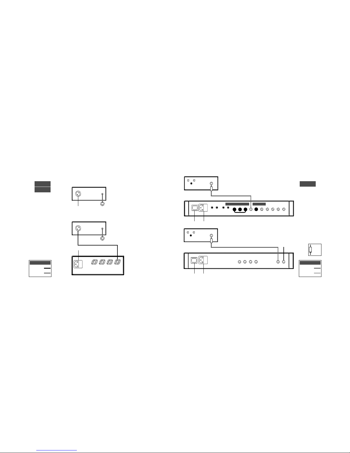
cds connection to xps power supply
cds
xps
cd players
cds
2
track
time
repeat
program
to preamplifier
mains input
to preamplifier
5-5 180˚ DIN
11-11 Burndy
Interconnects
display
previous
next
pause
stop
play
ch1
nc
nc
-ve
ch2
cds output
5
cd players
cdx connection to xps power supply
cdx
xps
cd players
cdx
4
pause
time
repeat
program
link plug fitted
to preamplifier
mains input
power switch
to preamplifier
cable
direction
marker
5-5 180˚ DIN
11-11 Burndy
Interconnects
mains input
note
Do not connect the cdx to mains power.
ch1
nc
nc
-ve
ch2
cdx output
previous
next
stop
play
7
cd players
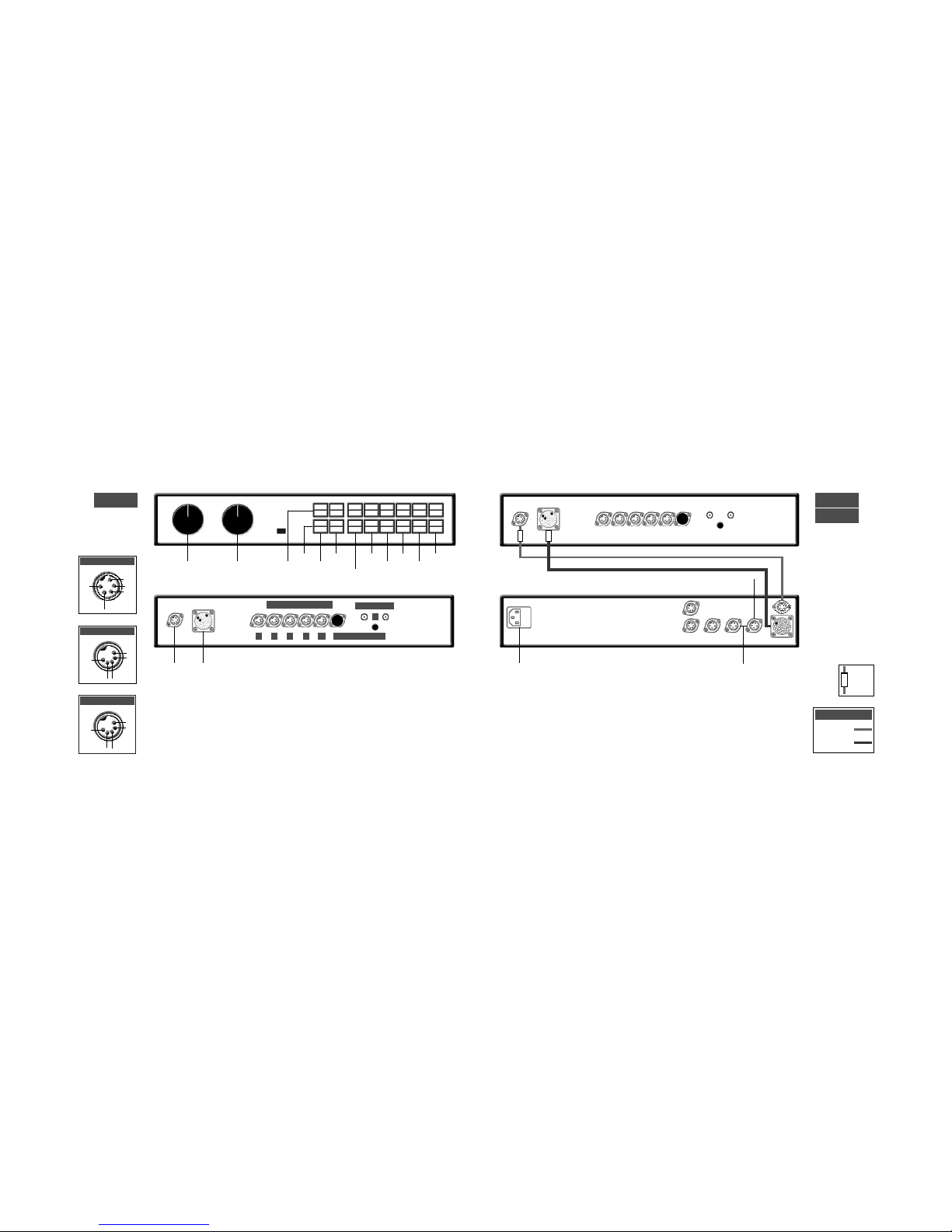
cd5 connection to flatcap 2 power supply
cd players
6
link plug fitted
to preamplifier
rc5 input
link plug removed
to preamplifier
ch1
nc
nc
-ve
ch2
cd5 output
cable
direction
marker
5-5 180˚ DIN
5-5 240˚ DIN
Interconnects
cd5
flatcap 2
cd5
previous
next
stop
play
note
cd5 players manufactured after April 2001 are fitted
with an RC5 control input. This input is designed to
accept external control signals for multi-room
applications. Contact your dealer for further
information on its use.
mains input
power switch
mains input
power switch
mains input
power switch
9
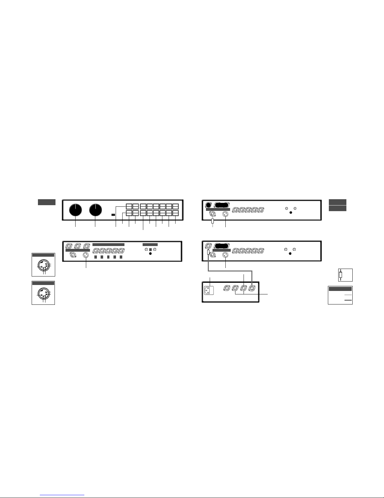
tuners
tuners
napst
nat 01
8
ch1
nc
nc
-ve
ch2
nat 01 output
nat 01 connection to napst power supply
to preamplifier
75 ohm FM aerial
mains input
rc5 input
cable
direction
marker
5-5 180˚ DIN
5-5 240˚ DIN
Interconnects
ch1
nc
nc
-ve
ch2
nat 02/05 output
75 ohm FM aerial
to preamplifier
75 ohm FM aerial
to preamplifier
nat 05
nat 02
note
The RC5 input is designed to accept
external control signals for multi-room
applications. Contact your dealer for
further information on its use.
mains input
power switch
power switch
mains input
to:
nac 52, nac 82, nac 102:
socket 4, 5 or 6.
nac 112, nait 5:
socket 3, 4 or 5.
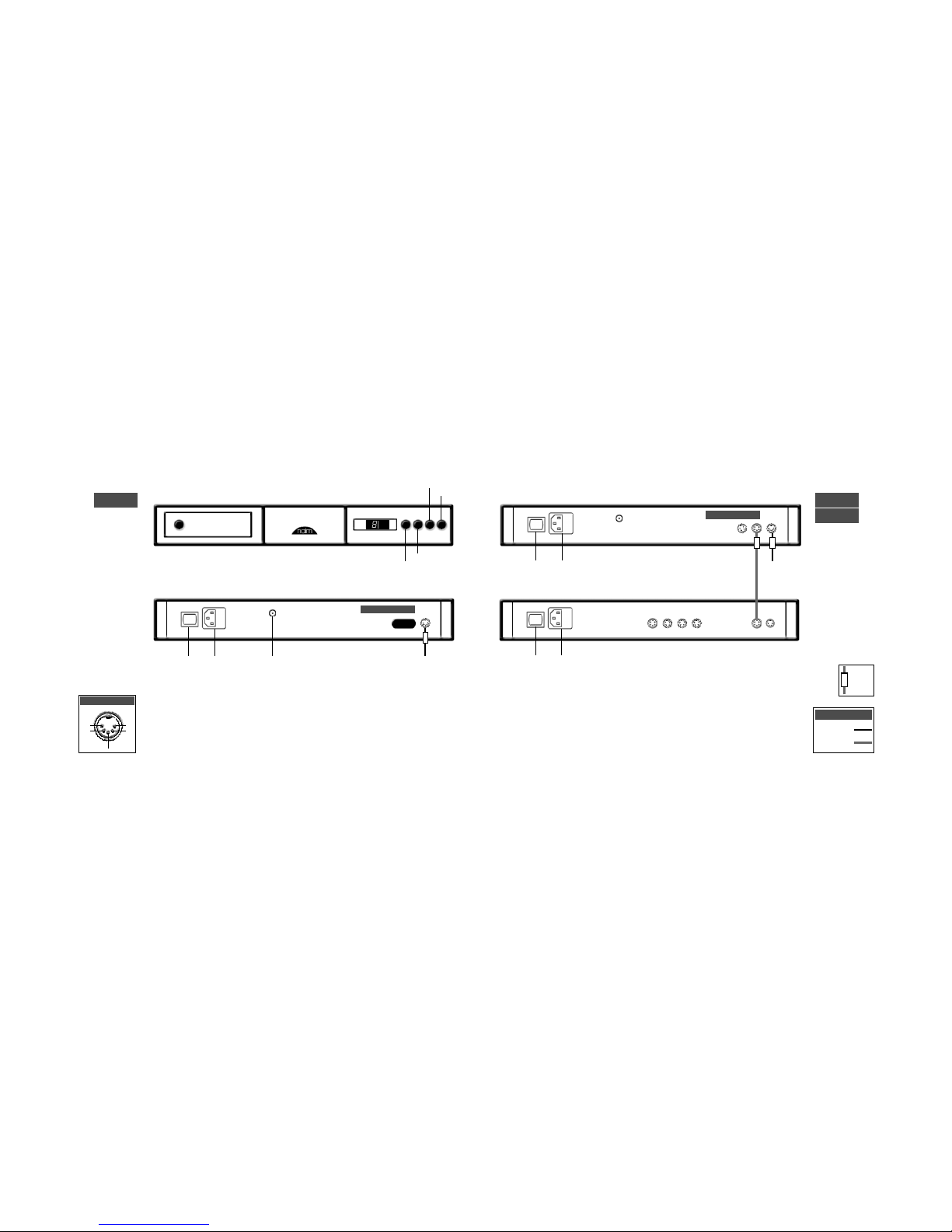
11
phono stage
stageline connection to nait 5 or nac 112
stageline connection to flatcap 2
stageline
headphone amplifier
headline connection to napsc or hi-cap power supply.
headline
10
from napsc
to:
nac 52, nac 82, nac 102:
socket 4, 5 or 6.
nac 112, nait 5:
socket 3, 4 or 5.
all link plugs fitted
cover fitted
5-2 SLIC
Captive 5/180˚ DIN
Interconnects
cable
direction
marker
hi-cap
to preamp. 4
to 5 pin
interconnect
required
mains input
mains input
power switch
mains input
power switch
5-5 240˚DIN
4-5 DIN
Interconnects
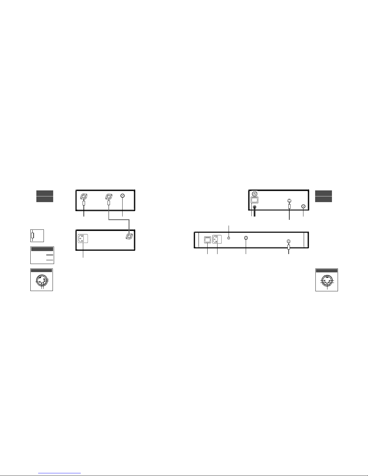
13
preamplifiers
nac 52 connection to supercap power supply
nac 52
supercap
preamplifiers
nac 52
12
6
5 4 3
2a 2b (blank fitted)
1
high level inputs
phono input
digital
power supply
audio power supply
ch1
nc
nc
-ve
ch2
inputs 3 & 2a
ch1
ch1
ch2
-ve
ch2
inputs 6, 5 & 4
input 2b
+ve
ch1
ch2
-ve
+ve
cable
direction
marker
5-5 240˚ DIN
16 -16 Burndy
Interconnects
1
inputs
mono
volume
balance
mute
2a/b
3
4
5
6
rec
source
to nap 140, 150 or 180 power amplifiers (4 pin DIN) or nap 250 power amplifier (4 DIN-XLR)
to nap 135 or nap 500 power amplifiers (4 pin to XLR)
mains input
15
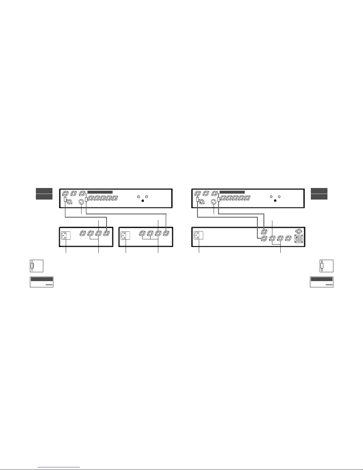
preamplifiers
nac 82 connection to nap 140, 150 and nap 180 power amplifiers
nac 82 connected to one hi-cap or flatcap 2
nac 82
hi-cap
preamplifiers
nac 82
14
6 5 4 3
2
1
high level inputs
outputs
phono input
napsc
link plugs fitted
napsc
to nap 140,150
& 180 power
amplifiers
link plug fitted
napsc
ch1
nc
nc
-ve
ch2
inputs 3 & 2
ch1
ch1
ch2
-ve
ch2
inputs 6, 5 & 4
note
The napsc power supply must
be connected to the nac 82 at
all times.
4-4 DIN to nap 140, 150 & 180
4 DIN-XLR to nap 250
4 DIN-XLR to
nap 135 & 500
cable
direction
marker
4-4 DIN
5-5 240˚ DIN
Interconnects
1
inputs
mono
volume
balance
mute
2
3
4
5
6
rec
source
mains input
17
preamplifiers
nac 82 connection to supercap
nac 82
supercap
preamplifiers
nac 82 connection to two hi-caps or flatcaps
nac 82
hi-cap
16
napsc
4-4 DIN to nap 140, 150 & 180
4 DIN-XLR to nap 250
4 DIN-XLR to
nap 135 & 500
all link plugs removed
napsc
all link plugs removed
4-4 DIN to nap 140, 150 & 180
4 DIN-XLR to nap 250
4 DIN-XLR to nap 135 & 500
cable
direction
marker
5-5 240˚ DIN
Interconnects
cable
direction
marker
5-5 240˚ DIN
Interconnects
note
Sound quality will be severely impaired if power
supplies are mixed. A flatcap together with a hi-cap
for example. Similarly, both outputs of a Flatcap 2
should not be used simultanesously to power one
preamp.
mains input
mains input
mains input
do not use
do not use
 Loading...