

Nad T770 User Manual [it]
T770
Surround Sound Receiver
Manuale delle Istruzioni
I
Warning: To reduce the risk of fire or electric shock,
do not expose this unit to rain or moisture.
The lightning flash with an arrowhead symbol within an equilateral triangle, is
intended to alert the user to the presence of uninsulated “dangerous voltage”
within the product’s enclosure that may be of sufficient magnitude to
constitute a risk of electric shock to persons.
The exclamation point within an equilateral triangle is intended to alert the
user to the presence of important operating and maintenance (servicing)
instructions in the literature accompanying the product.
Do not place this unit on an unstable cart, stand or tripod, bracket or table. The
unit may fall, causing serious injury to a child or adult and serious damage to
the unit. Use only with a cart, stand, tripod, bracket or table recommended by
the manufacturer or sold with the unit. Any mounting of the device on a wall
or ceiling should follow the manufacturer’s instructions and should use a
mounting accessory recommended by the manufacturer.
An appliance and cart combination should be moved with care. Quick stops,
excessive force and uneven surfaces may cause the appliance and cart
combination to overturn.
Read and follow all the safety and operating instructions before connecting or
using this unit. Retain this notice and the owner’s manual for future reference.
All warnings on the unit and in its operating instructions should be adhered to.
Do not use this unit near water; for example, near a bath tub, washbowl,
kitchen sink, laundry tub, in a wet basement or near a swimming pool.
The unit should be installed so that its location or position does not interfere
with its proper ventilation. For example, it should not be situated on a bed,
sofa, rug or similar surface that may block the ventilation openings; or placed
in a built-in installation, such as a bookcase or cabinet, that may impede the
flow of air through its ventilation openings.
The unit should be situated from heat sources such as radiators, heat registers,
stoves or other devices (including amplifiers) that produce heat.
The unit should be connected to a power supply outlet only of the voltage and
frequency marked on its rear panel.
The power supply cord should be routed so that it is not likely to be walked on
or pinched, especially near the plug, convenience receptacles, or where the
cord exits from the unit.
Unplug the unit from the wall outlet before cleaning. Never use benzine,
thinner or other solvents for cleaning. Use only a soft damp cloth.
The power supply cord of the unit should be unplugged from the wall outlet
when it is to be unused for a long period of time.
Care should be taken so that objects do not fall, and liquids are not spilled into
the enclosure through any openings.
This unit should be serviced by qualified service personnel when:
A. The power cord or the plug has been damaged; or
B. Objects have fallen, or liquid has been spilled into the unit; or
C. The unit has been exposed to rain or liquids of any kind; or
D. The unit does not appear to operate normally or exhibits a marked change
in performance; or
E. The device has been dropped or the enclosure damaged.
DO NOT ATTEMPT SERVICING OF THIS UNIT
YOURSELF. REFER SERVICING TO QUALIFIED
SERVICE PERSONNEL
Upon completion of any servicing or repairs, request the service shop’s
assurance that only Factory Authorized Replacement Parts with the same
characteristics as the original parts have been used, and that the routine safety
checks have been performed to guarantee that the equipment is in safe
operating condition.
REPLACEMENT WITH UNAUTHORIZED PARTS MAY RESULT IN FIRE, ELECTRIC
SHOCK OR OTHER HAZARDS.
ATTENTION
POUR ÉVITER LES CHOC ELECTRIQUES, INTRODUIRE LA
LAME LA PLUS LARGE DE LA FICHE DANS LA BORNE
CORRESPONDANTE DE LA PRISE ET POUSSER JUSQU’AU
FOND.
CAUTION
TO PREVENT ELECTRIC SHOCK, MATCH WIDE BLADE OF
PLUG TO WIDE SLOT FULLY INSERT.
If an indoor antenna is used (either built into the set or installed separately),
never allow any part of the antenna to touch the metal parts of other electrical
appliances such as a lamp, TV set etc.
CAUTION
POWER LINES
Any outdoor antenna must be located away from all power lines.
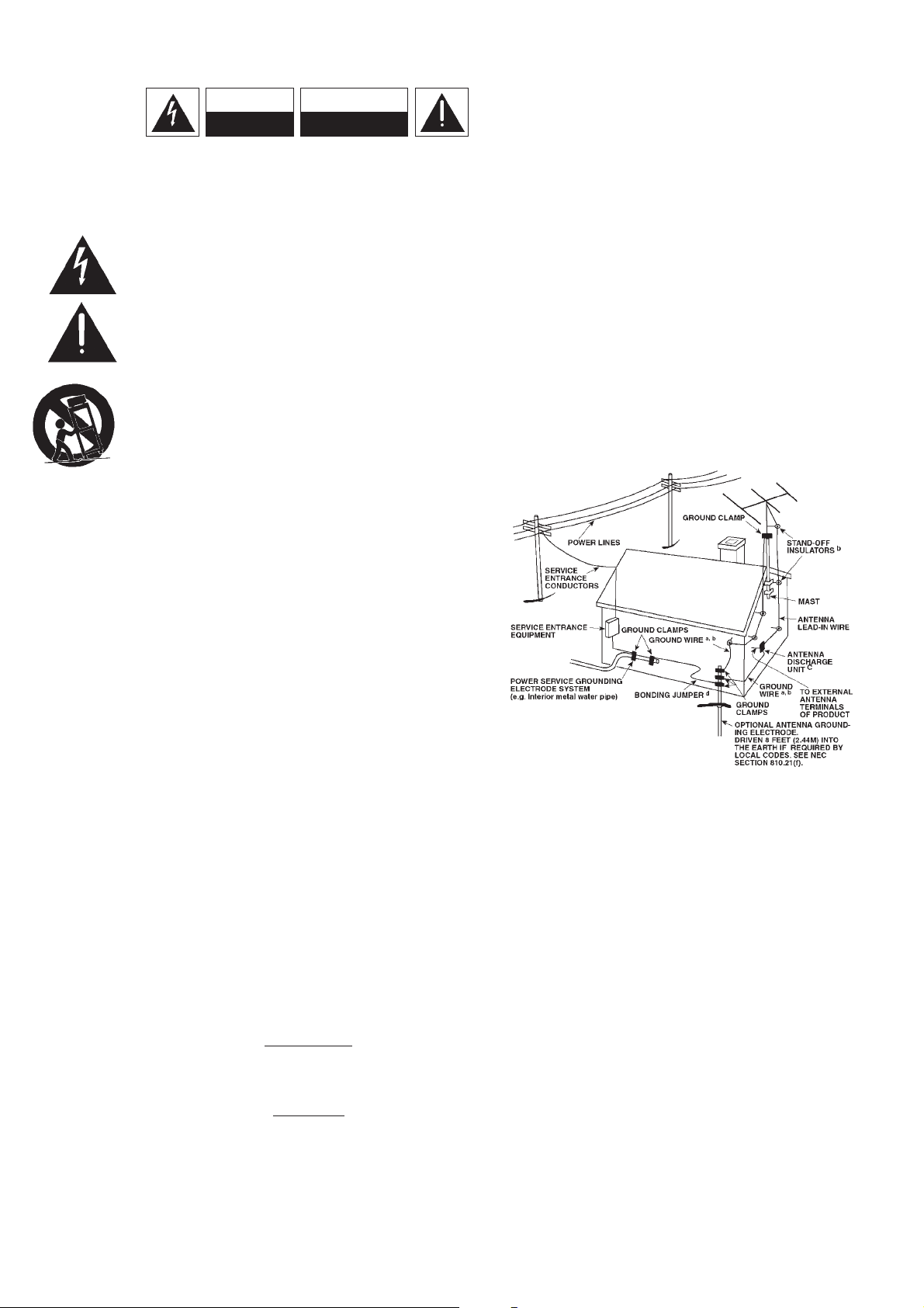
OUTDOOR ANTENNA GROUNDING
If an outside antenna is connected to your tuner or tuner-preamplifier, be sure
the antenna system is grounded so as to provide some protection against
voltage surges and built-up static charges. Article 810 of the National Electrical
Code, ANSI/NFPA No. 70-1984, provides information with respect to proper
grounding of the mast and supporting structure, grounding of the lead-in wire
to an antenna discharge unit, size of grounding conductors, location of
antenna discharge unit, connection to grounding electrodes and requirements
for the grounding electrode.
a. Use No. 10 AWG (5.3mm2) copper, No. 8 AWG (8.4mm2) aluminium, No. 17
AWG (1.0mm2) copper-clad steel or bronze wire, or larger, as a ground wire.
b. Secure antenna lead-in and ground wires to house with stand-off insulators
spaced from 4-6 feet (1.22 - 1.83 m) apart.
c. Mount antenna discharge unit as close as possible to where lead-in enters
house.
d. Use jumper wire not smaller than No.6 AWG (13.3mm2) copper, or the
equivalent, when a separate antenna-grounding electrode is used. see NEC
Section 810-21 (j).
EXAMPLE OF ANTENNA GROUNDING AS PER NATIONAL ELECTRICAL CODE
INSTRUCTIONS CONTAINED IN ARTICLE 810 - RADIO AND TELEVISION
EQUIPMENT.
NOTE TO CATV SYSTEM INSTALLER: This reminder is provided to call
the CATV system installer’s attention to Article 820-40 of the National Electrical
Code that provides guidelines for proper grounding and, in particular, specifies
that the ground cable ground shall be connected to the grounding system of
the building, as close to the point of cable entry as practical.
FOR U.S.A. MODEL
FCC INFORMATION FOR USER
CAUTION: Changes or modifications not expressly approved by the
manufacturer for compliance could void the user’s authority to operate.
NOTE: This equipment has been tested and found to comply with the limits
for a Class B digital device, pursuant to part 15 of the FCC Rules. These limits
are designed to provide reasonable protection against harmful interference in a
residential installation. This equipment generates, uses, and can radiate radio
frequency energy and, if not installed and used in accordance with the
instructions, may cause harmful interference to radio communications.
However, there is no guarantee that interference will not occur in a particular
installation. If this equipment does cause harmfiul interference to radio or
television reception, which can be determined by turning the equipment off
and on, the user is encouraged to try to correct the interference by one or
more of the following measures:
• Reorient or relocate the receiving antenna.
• Increase the separation between the equipment and receiver.
• Connect the equipment into an outlet on a circuit different from that to
which the receiver is connected.
• Consult the dealer or an experienced radio/TV technician for help.
CAUTION
RISK OF ELECTRIC
SHOCK DO NOT OPEN
ATTENTION:
RISQUE DE CHOC ELECTRIQUE
NE PAS OUVRIR
CAUTION: TO REDUCE THE RISK OF ELECTRIC
SHOCK, DO NOT REMOVE COVER (OR BACK). NO
USER SERVICEABLE PARTS INSIDE. REFER SERVICING
TO QUALIFIED SERVICE PERSONNEL.
IMPORTANT SAFETY INSTRUCTIONS
2
3
FRONT PANEL CONTROLS
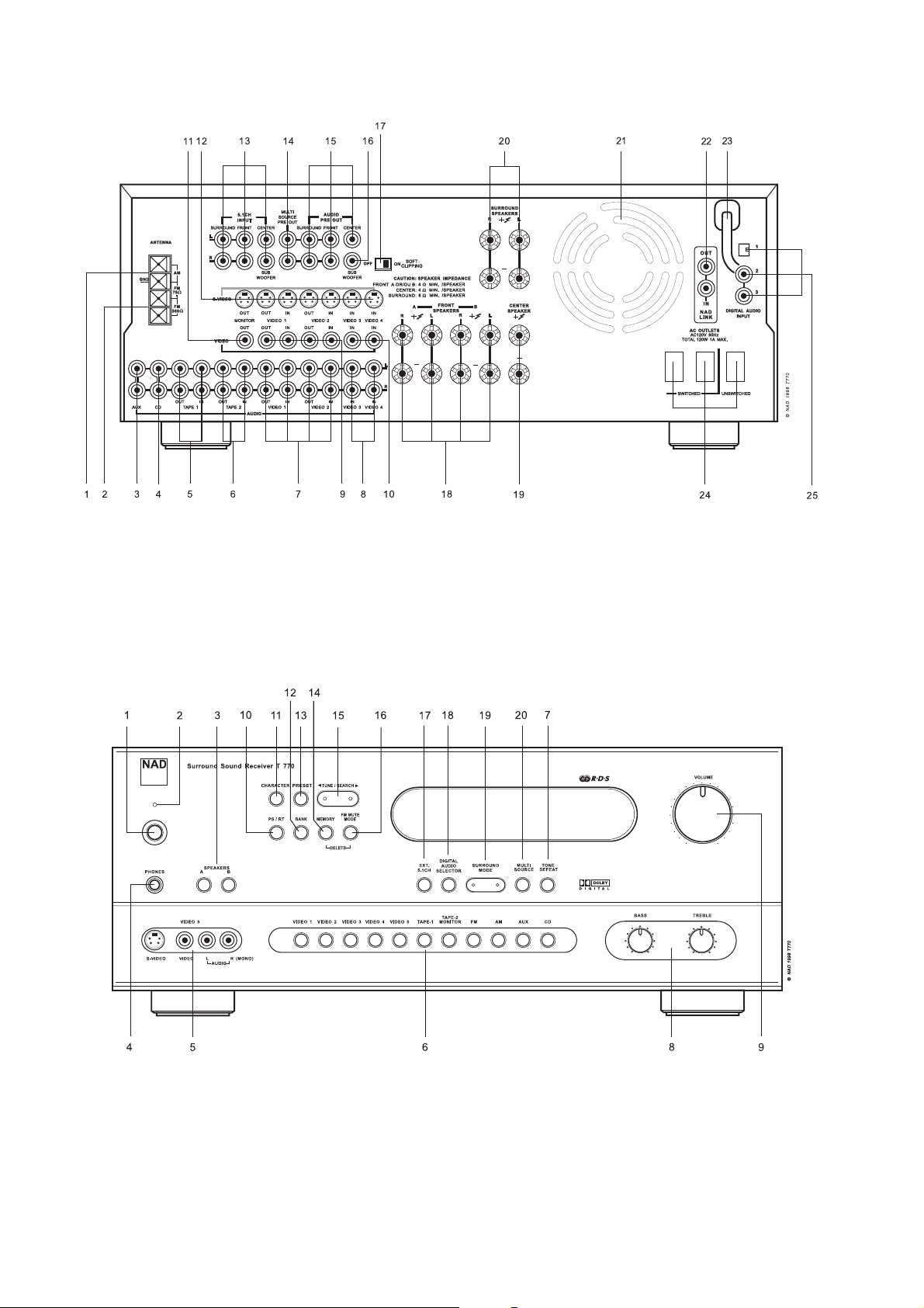
REAR PANEL CONNECTIONS
4
5
FIGURE B
FIGURE A
6
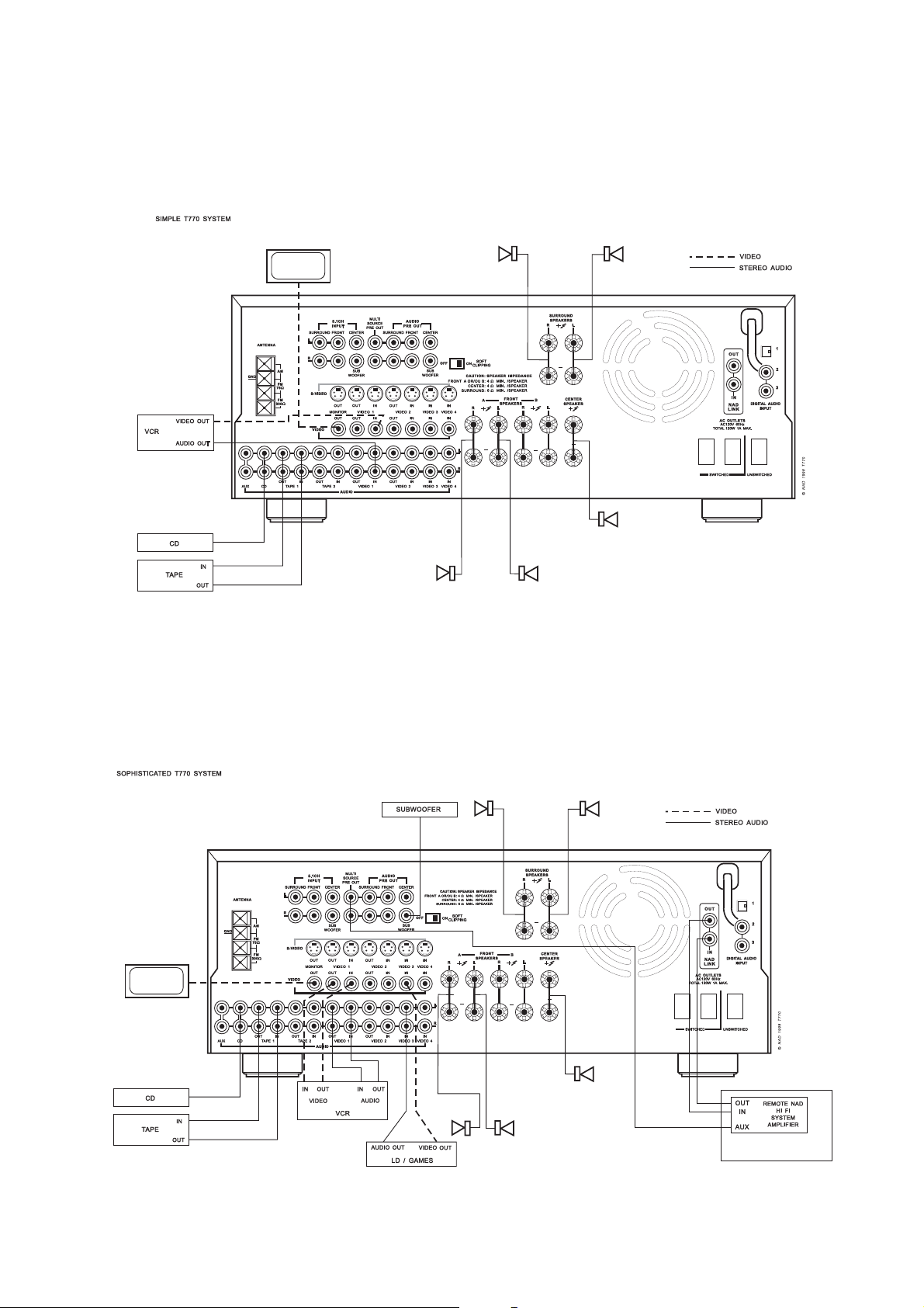
FIGURE 1
FIGURE 2
FIGURE 3
FIGURE 4

7
FIGURE 5
1
5
6
9
2
3
4
7
8
11
10
13
14
12
15
16

NOTE RELATIVE ALL’INSTALLAZIONE
Il NAD T770 va sempre collocato in piano su una superficie
robusta. Evitare di collocare l’unità in posizioni assolate oppure
vicino a fonti di calore o umidità. Assicurarsi che vi sia
ventilazione sufficiente. Non collocare l’unità su superficie soffice,
quale ad esempio tappeti e stuoie. Non collocare l’unità in aree
chiuse, ad esempio dentro librerie o scaffali che possono
impedire il passaggio di aria attraverso le griglie di ventilazione.
Assicurarsi che l’unità sia spenta prima di perfezionare qualsiasi
collegamento.
Le prese RCA sul NAD T770 sono contraddistinte da codice colori
per maggior convenienza. Rosso e verde indicano rispettivamente
audio destro e sinistro; arancione è per l’input digitale, nero per
il segnale digitale modulato RF, giallo per il Video Composite e il
NAD Link. Per garantire prestazioni ottimali e la massima
affidabilità delle connessioni, impiegare sempre ed
esclusivamente cavi e prese di marca. I cavi RCA audio funzionano
perfettamente per i segnali video, peraltro si raccomanda di
impiegare i cavi speciali per video, se possibile. Per gli input
digitali si richiedono cavi speciali realizzati specificatamente per il
trasferimento dei segnali digitali. Assicurarsi che i cavi e i
connettori non siano danneggiati ed accertarsi che tutti i
connettori siano ben calzati.
Per assicurare prestazioni perfette, impiegare sempre cavi di
marca per gli altoparlanti, calibratura 16 (1.5 mm) o spessore
maggiore.
Se non si intende impiegare l’unità per un certo periodo di tempo,
scollegare la spina dalla presa della C.A.
Se il NAD T770 venisse contaminato da acqua, spegnere
l’alimentazione elettrica e scollegare la spina dalla presa della C.A.
Fare controllare l’unità da un tecnico specializzato prima di
cercare di accenderla.
Non staccare il coperchio: si fa notare che al suo interno
non vi sono componenti riparabili dall’Utente.
Pulire l’unità impiegando un panno soffice ed asciutto. Se
necessario, inumidire leggermente il panno con un po’ di acqua
e sapone. Non impiegare soluzioni a base di benzolo o altri
prodotti volatili.
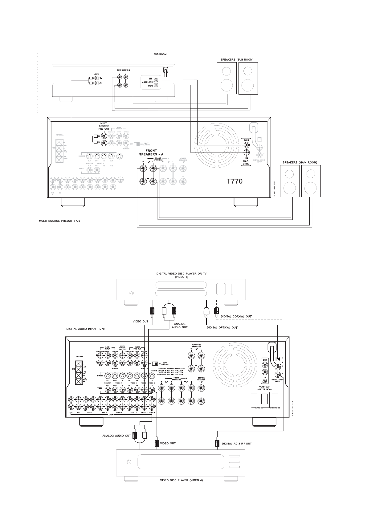
CONNESSIONI AL PANNELLO POSTERIORE
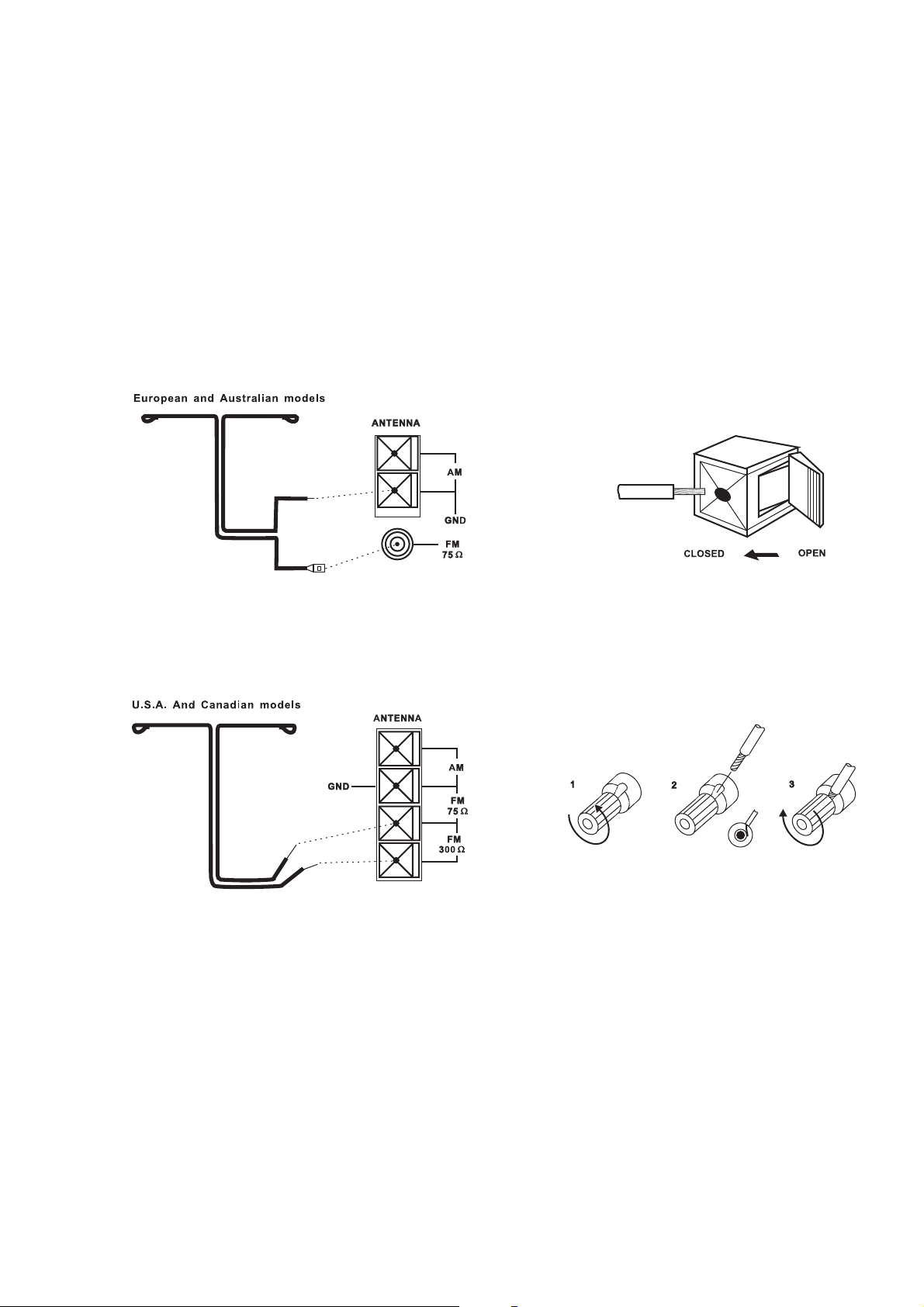
1. ANTENNA AM
Il modello T770 è fornito di un’antenna AM a filo aereo che serve
per garantire la ricezione delle stazioni a modulazione d’ampiezza
(A.M.). Aprire la levetta del terminale a graffa ed inserire il cavo
dall’antenna. Il cavo viene pizzicato saldamente quando la levetta
è chiusa (Fig. 3). Sperimentare l’orientamento dell’antenna
assicurandosi sempre che il cerchio sia in verticale per garantire
una buona ricezione. La ricezione può essere pregiudicata se
l’antenna viene collocata accanto a componenti metallici, quali
scaffali o termosifoni.
NOTA: Quando la ricezione non è perfetta impiegando solo
l’antenna AM fornita, si consiglia allora di ricorrere ad un’antenna
esterna. Non collegare nessun altro tipo di antenna al terminale
AM marcato ANTENNA. Non staccare l’antenna AM. Il cavo
dell’antenna non deve superare tre metri.
2. ANTENNA FM
L’unità è dotata anche di un’antenna a piattina per le stazioni a
modulazione di frequenza (FM); questa va collegata al connettore
FM sul retro dell’unità (Fig. 1, Fig. 2). L’antenna a piattina va
montata su una superficie verticale, in modo che formi una “T”.
Orientare l’antenna in varie posizioni per individuare quella
migliore, ottenendo cioè il massimo segnale possibile con minimo
rumore di fondo. Un segnale FM non perfetto dà di solito sibilo
molto forte, specie in ascolto stereo, nonché interferenze da fonti
elettriche esterne. Se la ricezione FM è molto scadente, è possibile
peraltro migliorare le prestazioni del sintonizzatore impiegando
un’antenna FM esterna. Interpellare a questo proposito un tecnico
specializzato che provvederà ad installare l’antenna nel modo
migliore possibile a seconda della zona.
3. “AUX INPUT” - INPUT GRUPPI AULISIARI
Input per i componenti audio. Impiegare un doppio cavo RCARCA per collegare gli “Audio Outputs” sinistro e destro del
componenti audio a questo input.
4. INPUT CD
Input per il riproduttore per CD (segnale audio analogico) o altra
fonte di segnale di livello. Impiegare un doppio cavo RCA-RCA per
collegare gli output di livello sinistra e destra “Audio Outputs” del
riproduttore per CD a questo input.
5. NASTRO 1
Connessioni per registrazione ed ascolto analogici ad un
registratore a nastro di qualsiasi tipo, quale ad esempio a cassette,
a bobina, DAT, MD oppure DCC. Impiegando doppi cavi RCA-RCA
collegare “Audio Output” sinistro e destro del registratore ai
connettori “TAPE 1 IN” per l’ascolto. Collegare “Audio Input”
sinistro e destro del registratore ai connettori “TAPE 1 OUT” per
la registrazione.
6. NASTRO 2
Connessioni per registrazione ed ascolto analogici ad un secondo
registratore a nastro di qualsiasi tipo. Impiegando doppi cavi RCARCA collegare “Audio Output” sinistro e destro del registratore ai
connettori “TAPE 2 IN” per l’ascolto. Collegare “Audio Input”
sinistro e destro del registratore ai connettori “TAPE 2 OUT” per
la registrazione.
7. VIDEO 1 E VIDEO 2 (AUDIO)
Connessioni per registrazione ed ascolto ad un VCR o altro
videoregistratore. Impiegando doppi cavi RCA-RCA collegare
“Audio Out” sinistro e destro del VCR ai connettori di VIDEO 1
oppure VIDEO 2 per l’ascolto. Collegare “Audio In” sinistro e
destro del VCR ai connettori VIDEO 1 oppure VIDEO 2 OUT per la
registrazione. Gli input ed output audio sono impiegati unitamente
agli input ed output per il video composito (linea) (vedere il No.
9 qui sotto) oppure S-VIDEO (vedere il No. 12 qui sotto).
8. VIDEO 3 E VIDEO 4 (AUDIO)
Gli input per l’ascolto da un VCR o altro apparecchio video, quale
ad esempio TV stereo, ricevitore TV via satellite o cavo oppure
riproduttore per dischi laser LD. Impiegando doppi cavi RCA-RCA,
collegare ad “Audio Out” sinistro e destro del
VCR/TD/LD/ricevitore per trasmissioni tramite satellite a questi
input. Gli input audio sono impiegati unitamente agli input per il
video composito (linea) (vedere il No. 10 qui sotto) oppure SVIDEO (vedere il No. 12 qui sotto).
I
22
NAD T770 Surround Sound AM/FM Receiver
 Loading...