

Nad T770 User Manual [pt]
T770
Surround Sound Receiver
Manual do Proprietário
P
Warning: To reduce the risk of fire or electric shock,
do not expose this unit to rain or moisture.
The lightning flash with an arrowhead symbol within an equilateral triangle, is
intended to alert the user to the presence of uninsulated “dangerous voltage”
within the product’s enclosure that may be of sufficient magnitude to
constitute a risk of electric shock to persons.
The exclamation point within an equilateral triangle is intended to alert the
user to the presence of important operating and maintenance (servicing)
instructions in the literature accompanying the product.
Do not place this unit on an unstable cart, stand or tripod, bracket or table. The
unit may fall, causing serious injury to a child or adult and serious damage to
the unit. Use only with a cart, stand, tripod, bracket or table recommended by
the manufacturer or sold with the unit. Any mounting of the device on a wall
or ceiling should follow the manufacturer’s instructions and should use a
mounting accessory recommended by the manufacturer.
An appliance and cart combination should be moved with care. Quick stops,
excessive force and uneven surfaces may cause the appliance and cart
combination to overturn.
Read and follow all the safety and operating instructions before connecting or
using this unit. Retain this notice and the owner’s manual for future reference.
All warnings on the unit and in its operating instructions should be adhered to.
Do not use this unit near water; for example, near a bath tub, washbowl,
kitchen sink, laundry tub, in a wet basement or near a swimming pool.
The unit should be installed so that its location or position does not interfere
with its proper ventilation. For example, it should not be situated on a bed,
sofa, rug or similar surface that may block the ventilation openings; or placed
in a built-in installation, such as a bookcase or cabinet, that may impede the
flow of air through its ventilation openings.
The unit should be situated from heat sources such as radiators, heat registers,
stoves or other devices (including amplifiers) that produce heat.
The unit should be connected to a power supply outlet only of the voltage and
frequency marked on its rear panel.
The power supply cord should be routed so that it is not likely to be walked on
or pinched, especially near the plug, convenience receptacles, or where the
cord exits from the unit.
Unplug the unit from the wall outlet before cleaning. Never use benzine,
thinner or other solvents for cleaning. Use only a soft damp cloth.
The power supply cord of the unit should be unplugged from the wall outlet
when it is to be unused for a long period of time.
Care should be taken so that objects do not fall, and liquids are not spilled into
the enclosure through any openings.
This unit should be serviced by qualified service personnel when:
A. The power cord or the plug has been damaged; or
B. Objects have fallen, or liquid has been spilled into the unit; or
C. The unit has been exposed to rain or liquids of any kind; or
D. The unit does not appear to operate normally or exhibits a marked change
in performance; or
E. The device has been dropped or the enclosure damaged.
DO NOT ATTEMPT SERVICING OF THIS UNIT
YOURSELF. REFER SERVICING TO QUALIFIED
SERVICE PERSONNEL
Upon completion of any servicing or repairs, request the service shop’s
assurance that only Factory Authorized Replacement Parts with the same
characteristics as the original parts have been used, and that the routine safety
checks have been performed to guarantee that the equipment is in safe
operating condition.
REPLACEMENT WITH UNAUTHORIZED PARTS MAY RESULT IN FIRE, ELECTRIC
SHOCK OR OTHER HAZARDS.
ATTENTION
POUR ÉVITER LES CHOC ELECTRIQUES, INTRODUIRE LA
LAME LA PLUS LARGE DE LA FICHE DANS LA BORNE
CORRESPONDANTE DE LA PRISE ET POUSSER JUSQU’AU
FOND.
CAUTION
TO PREVENT ELECTRIC SHOCK, MATCH WIDE BLADE OF
PLUG TO WIDE SLOT FULLY INSERT.
If an indoor antenna is used (either built into the set or installed separately),
never allow any part of the antenna to touch the metal parts of other electrical
appliances such as a lamp, TV set etc.
CAUTION
POWER LINES
Any outdoor antenna must be located away from all power lines.
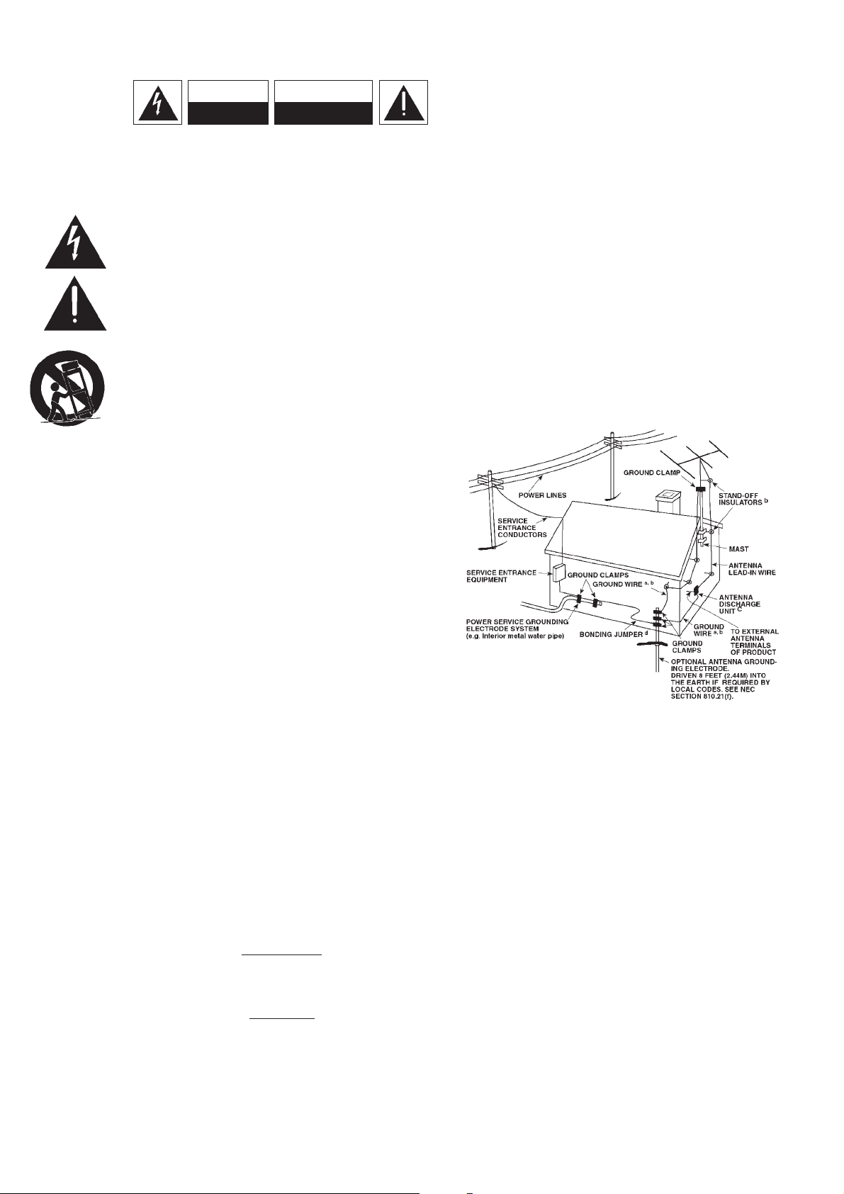
OUTDOOR ANTENNA GROUNDING
If an outside antenna is connected to your tuner or tuner-preamplifier, be sure
the antenna system is grounded so as to provide some protection against
voltage surges and built-up static charges. Article 810 of the National Electrical
Code, ANSI/NFPA No. 70-1984, provides information with respect to proper
grounding of the mast and supporting structure, grounding of the lead-in wire
to an antenna discharge unit, size of grounding conductors, location of
antenna discharge unit, connection to grounding electrodes and requirements
for the grounding electrode.
a. Use No. 10 AWG (5.3mm2) copper, No. 8 AWG (8.4mm2) aluminium, No. 17
AWG (1.0mm2) copper-clad steel or bronze wire, or larger, as a ground wire.
b. Secure antenna lead-in and ground wires to house with stand-off insulators
spaced from 4-6 feet (1.22 - 1.83 m) apart.
c. Mount antenna discharge unit as close as possible to where lead-in enters
house.
d. Use jumper wire not smaller than No.6 AWG (13.3mm2) copper, or the
equivalent, when a separate antenna-grounding electrode is used. see NEC
Section 810-21 (j).
EXAMPLE OF ANTENNA GROUNDING AS PER NATIONAL ELECTRICAL CODE
INSTRUCTIONS CONTAINED IN ARTICLE 810 - RADIO AND TELEVISION
EQUIPMENT.
NOTE TO CATV SYSTEM INSTALLER: This reminder is provided to call
the CATV system installer’s attention to Article 820-40 of the National Electrical
Code that provides guidelines for proper grounding and, in particular, specifies
that the ground cable ground shall be connected to the grounding system of
the building, as close to the point of cable entry as practical.
FOR U.S.A. MODEL
FCC INFORMATION FOR USER
CAUTION: Changes or modifications not expressly approved by the
manufacturer for compliance could void the user’s authority to operate.
NOTE: This equipment has been tested and found to comply with the limits
for a Class B digital device, pursuant to part 15 of the FCC Rules. These limits
are designed to provide reasonable protection against harmful interference in a
residential installation. This equipment generates, uses, and can radiate radio
frequency energy and, if not installed and used in accordance with the
instructions, may cause harmful interference to radio communications.
However, there is no guarantee that interference will not occur in a particular
installation. If this equipment does cause harmfiul interference to radio or
television reception, which can be determined by turning the equipment off
and on, the user is encouraged to try to correct the interference by one or
more of the following measures:
• Reorient or relocate the receiving antenna.
• Increase the separation between the equipment and receiver.
• Connect the equipment into an outlet on a circuit different from that to
which the receiver is connected.
• Consult the dealer or an experienced radio/TV technician for help.
CAUTION
RISK OF ELECTRIC
SHOCK DO NOT OPEN
ATTENTION:
RISQUE DE CHOC ELECTRIQUE
NE PAS OUVRIR
CAUTION: TO REDUCE THE RISK OF ELECTRIC
SHOCK, DO NOT REMOVE COVER (OR BACK). NO
USER SERVICEABLE PARTS INSIDE. REFER SERVICING
TO QUALIFIED SERVICE PERSONNEL.
IMPORTANT SAFETY INSTRUCTIONS
2
3
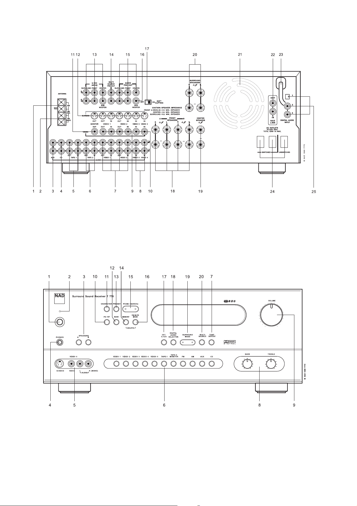
FRONT PANEL CONTROLS
REAR PANEL CONNECTIONS
4
5
FIGURE B
FIGURE A
6
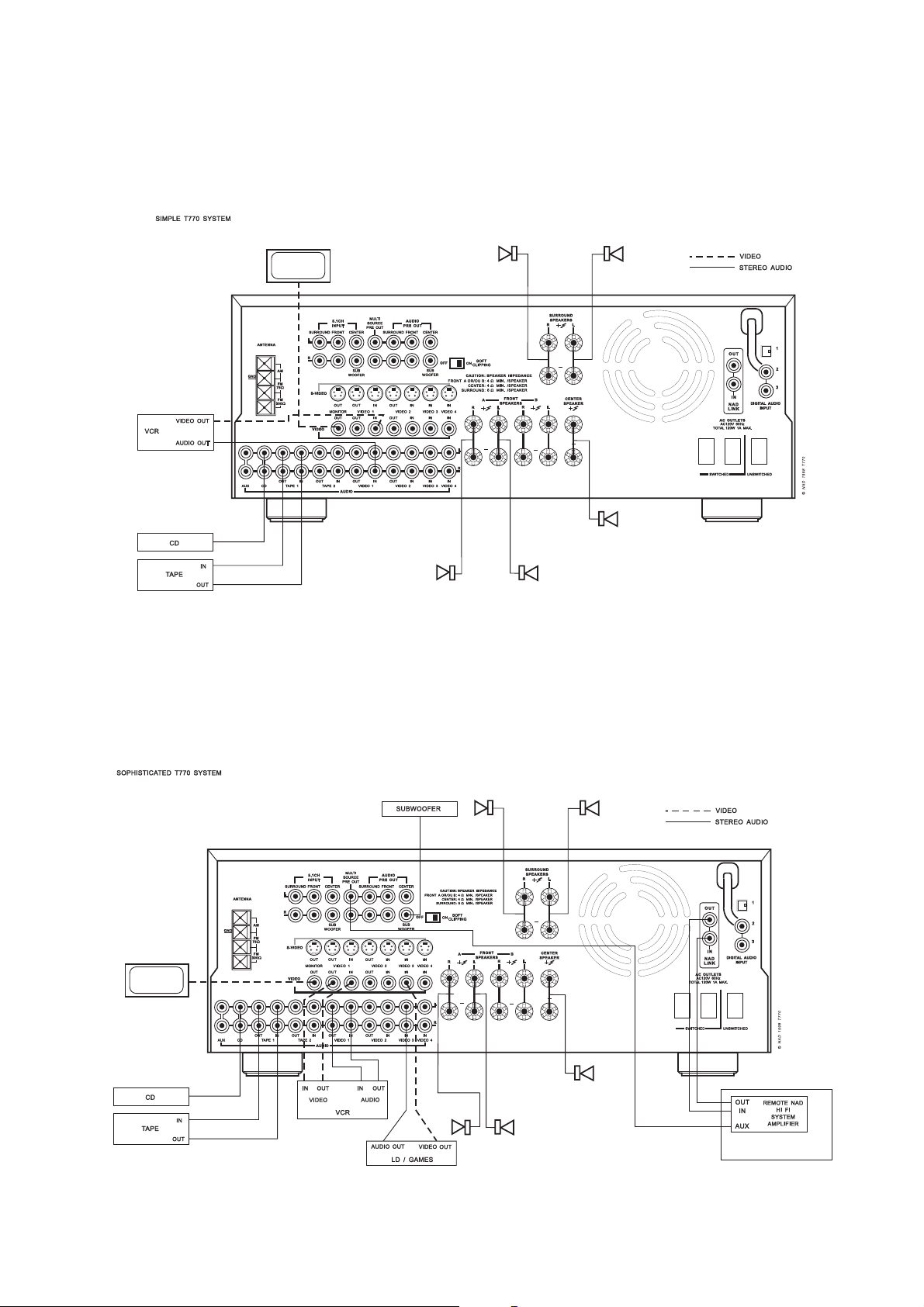
FIGURE 1
FIGURE 2
FIGURE 3
FIGURE 4
7
FIGURE 5
1
5
6
9
2
3
4
7
8
11
10
13
14
12
15
16

OBSERVAÇÕES SOBRE A INSTALAÇÃO
O seu receptor NAD T770 deverá ser instalado sobre uma
superfície nivelada, e sem vibrações. Evite instalar a unidade de
modo a que esta fique directamente exposta aos raios solares, ou
junto a fontes de calor e humidade.
Garanta uma ventilação adequada da unidade. Não coloque a
unidade sobre uma superfície mole, como por exemplo uma
alcatifa. Não coloque a unidade num espaço fechado, como seja
uma estante para livros ou um armário, que possa impedir o fluxo
do ar através das aberturas de ventilação.
Certifique-se que a unidade se encontra desligada antes de
efectuar quaisquer ligações.
Os terminais RCA do seu receptor NAD T770 encontram-se
codificados através de cores por uma questão de facilidade de
identificação. Vermelho e branco correspondem aos canais audio
Right (direito) e Left (esquerdo) respectivamente, cor de laranja
para a entrada digital, preto para o sinal digital modulado RF e
amarelo para a Composição Vídeo e para o NAD Link
(interligação NAD).
Utilize terminais e cabos de alta qualidade, por forma a obter uma
performance e uma fiabilidade óptimas. Os cabos RCA do circuito
de audio funcionarão perfeita e adequadamente no caso de sinais
vídeo, apesar de se recomendar a utilização de cabos específicos
para sinais vídeo sempre que for possível. Para as entradas
digitais, utilize cabos específicos para a transferência e condução
de sinais digitais. Certifique-se que os terminais e os cabos não
apresentam danos de qualquer natureza, e de que todos os
terminais se encontram bem ligados.
Por forma a obter uma melhor performance, utilize cabos de
altifalantes de alta qualidade, com uma espessura de bitola igual
ou superior a 16 (1,5 mm).
Se a unidade não for utilizada durante algum tempo, desligue a
ficha da tomada de alimentação de CA.
No caso de cair água em cima do seu receptor NAD T770,
desligue a alimentação da unidade, e retire a ficha da tomada de
alimentação de CA. Antes de voltar a utilizar a unidade, certifiquese que a mesma é inspeccionada por um técnico qualificado do
serviço de assistência.
Não retire a tampa; no interior da unidade não existem
componentes que possam ser reparadas pelo utilizador.
Utilize um pano macio e seco para limpar a unidade. Se
necessário, humedeça ligeiramente o pano com água com sabão.
Não utilize soluções que contenham benzol ou outros agentes
voláteis.
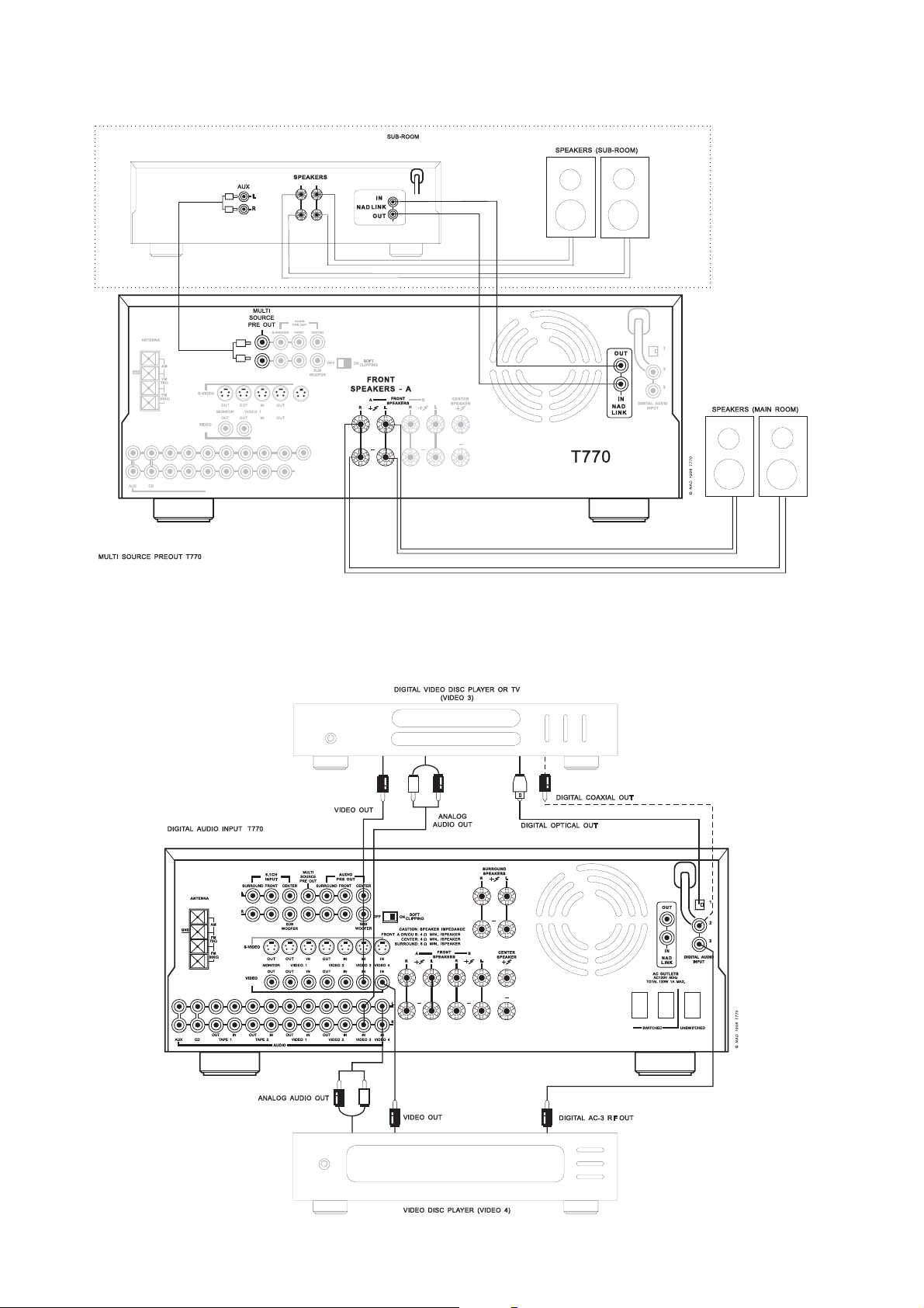
LIGAÇÕES DO PAINEL TRASEIRO
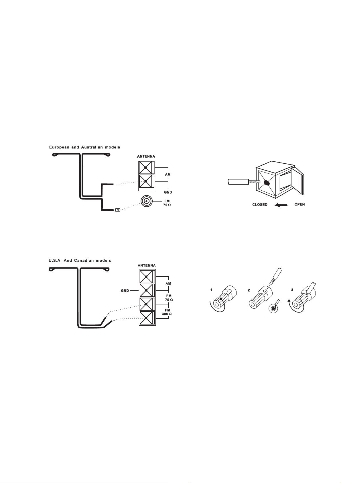
1. ANTENA AM
Com o receptor NAD T770 é fornecida uma antena de quadro AM
que é necessária para a recepção de sinais AM. Para ligar a antena
AM, em primeiro lugar, abra as patilhas dos terminais de ligação
e introduza a extremidade dos cabos da antena nas aberturas dos
terminais. Ao fechar as patilhas irá fixar os cabos na sua posição
(ver figura 3). Experimente diversas posições para a antena mas
certifique-se sempre que o anel da antena é colocado
verticalmente por forma a obter uma melhor recepção. A
colocação da antena junto a artigos metálicos de dimensões
apreciáveis como sejam prateleiras de metal ou radiadores,
poderá interferir na qualidade da recepção.
NOTA: Sempre que a qualidade da recepção não seja satisfatória
utilizando apenas a antena de quadro AM fornecida com a
unidade, recomenda-se que se ligue uma antena externa. Não
ligue qualquer outro cabo ao terminal da ANTENA AM para além
do cabo da antena de quadro. Não retire a antena de quadro AM.
O comprimento do cabo de antena para a antena de quadro não
deverá exceder os 3 metros.
2. ANTENA FM
É incluída uma antena de FM em cabo de fita, que deverá ser
ligada ao terminal da Antena FM situado na parte traseira da
unidade (ver figura 1, figura 2). A antena de fita deverá ser
instalada sobre uma superfície vertical, e disposta de modo a
formar um “T”.
Experimente colocar a antena em vários locais de modo a
determinar a posição que permite obter a melhor recepção de
sinal, e o menor ruído de fundo. Um sinal FM inadequado
normalmente conduz a níveis elevados de ruído, especialmente
no caso de recepção estéreo, bem como a interferências
provocadas por fontes eléctricas externas. Nas zonas em que a
recepção estéreo é fraca, a performance da secção do
sintonizador poderá ser melhorada através da utilização de uma
antena de FM instalada no exterior. Um técnico qualificado de
montagem de antenas poderá aconselhá-lo, e proceder à
instalação da antena recomendada, tendo em conta as suas
condições de recepção.
3. AUX INPUT (ENTRADA AUX)
Entrada para componentes audio. Utilize um cabo bifilar RCApara-RCA para ligar as “Saídas Audio” esquerda e direita do
componente audio a esta entrada.
4. CD INPUT (ENTRADA DO LEITOR DE
DISCOS COMPACTOS)
Entrada para um leitor de CD´s (sinal audio analógico) ou outra
fonte de sinal do nível de linha. Utilize um cabo bifilar RCA-paraRCA para ligar as “Saídas Audio” esquerda e direita do Leitor de
Discos Compactos a esta entrada.
5. TAPE 1
Ligações destinadas à gravação e reprodução analógica para um
gravador de cassetes audio de qualquer tipo como por exemplo
um leitor de cassetes, de bobinas, DAT, MD ou DCC. Com a ajuda
de um cabo bifilar RCA-para-RCA, ligue as “Saídas Audio”
esquerda e direita do gravador de cassetes aos terminais TAPE 1
IN (ENTRADA DO GRAVADOR 2) para iniciar a leitura e audição
da cassete. Ligue as “Entradas Audio” esquerda e direita do
gravador de cassetes aos terminais TAPE 1 OUT (SAÍDA DO
GRAVADOR 1) para a gravação de cassetes.
6. TAPE 2
Ligações destinadas à gravação e reprodução analógica para um
gravador de cassetes audio de qualquer tipo. Com a ajuda de um
cabo bifilar RCA-para-RCA, ligue as “Saídas Audio” esquerda e
direita do gravador de cassetes aos terminais TAPE 2 IN
(ENTRADA DO GRAVADOR 2) para iniciar a leitura e audição da
cassete. Ligue as “Entradas Audio” esquerda e direita do gravador
de cassetes aos terminais TAPE 2 OUT (SAÍDA DO GRAVADOR 1)
para a gravação de cassetes.
P
38
NAD T770 Receptor de Son Envolvente
 Loading...