

Page 1
®
CI9060/9120
Six Channel Amplifier
Twelve Channel Amplifier
ENGLISH
FRANÇAISDEUTSCH
Owner’s Manual
Manuel d’Installation
Bedienungsanleitung
Manual del Usuario
Manuale delle Istruzioni
Manual do Proprietário
Bruksanvisning
Gebruikershandleiding
ESPAÑOL
ITALIANOPORTUGUÊS
SVENSKA
NEDERLANDS
Page 2

ENGLISH FRANÇAIS
DEUTSCH
NEDERLANDS
ESPAÑOL
ITALIANO
PORTUGUÊS
SVENSKA
2
Page 3

TABLE OF CONTENTS
I Introduction . . . . . . . . . . . . . . . . . . . . . . . . . . . . . . . . . . . . . . . . . . . . . . . . . . . . . . . . . . . . . . .3-5
Note to Installation personnel . . . . . . . . . . . . . . . . . . . . . . . . . . . . . . . . . . . . . . . . . . . . . . . . . . . 3
Safety Instructions . . . . . . . . . . . . . . . . . . . . . . . . . . . . . . . . . . . . . . . . . . . . . . . . . . . . . . . . . . . 4
II Operation . . . . . . . . . . . . . . . . . . . . . . . . . . . . . . . . . . . . . . . . . . . . . . . . . . . . . . . . . . . . . . .6-10
NAD ATO Logic . . . . . . . . . . . . . . . . . . . . . . . . . . . . . . . . . . . . . . . . . . . . . . . . . . . . . . . . . . . . . 6
NAD OMC . . . . . . . . . . . . . . . . . . . . . . . . . . . . . . . . . . . . . . . . . . . . . . . . . . . . . . . . . . . . . . . . . 7
NAD Protection Circuitry. . . . . . . . . . . . . . . . . . . . . . . . . . . . . . . . . . . . . . . . . . . . . . . . . . . . . . . 7
Rear panel connections. . . . . . . . . . . . . . . . . . . . . . . . . . . . . . . . . . . . . . . . . . . . . . . . . . . . . . . . 8
Front panel connections . . . . . . . . . . . . . . . . . . . . . . . . . . . . . . . . . . . . . . . . . . . . . . . . . . . . . . 10
III Installation . . . . . . . . . . . . . . . . . . . . . . . . . . . . . . . . . . . . . . . . . . . . . . . . . . . . . . . . . . . . .11-16
Rack Mount . . . . . . . . . . . . . . . . . . . . . . . . . . . . . . . . . . . . . . . . . . . . . . . . . . . . . . . . . . . . . . . 11
Shelf Mount . . . . . . . . . . . . . . . . . . . . . . . . . . . . . . . . . . . . . . . . . . . . . . . . . . . . . . . . . . . . . . . 11
Speaker Hook-up . . . . . . . . . . . . . . . . . . . . . . . . . . . . . . . . . . . . . . . . . . . . . . . . . . . . . . . . . . . 12
Client Configuration (Flex-Pad) . . . . . . . . . . . . . . . . . . . . . . . . . . . . . . . . . . . . . . . . . . . . . . . . . 14
Client Configuration (input/channel destination) . . . . . . . . . . . . . . . . . . . . . . . . . . . . . . . . . . . . 15
IV Troubleshooting . . . . . . . . . . . . . . . . . . . . . . . . . . . . . . . . . . . . . . . . . . . . . . . . . . . . . . . . . . .17
V Specifications . . . . . . . . . . . . . . . . . . . . . . . . . . . . . . . . . . . . . . . . . . . . . . . . . . . . . . . . . . . . . .18
VI Fuse Replacement Chart . . . . . . . . . . . . . . . . . . . . . . . . . . . . . . . . . . . . . . . . . . . . . . . . . . . . .19
ATTENTION: INSTALLATION PERSONNEL
The mounting hardware was specifically engineered for the NAD CI-series amplifier. We recommend that
you do not substitute the mounting hardware.
Introduction
ENGLISH
FRANÇAISDEUTSCHNEDERLANDSESPAÑOL
Due to the high-power capability of the NAD CI-series amplifier, the power supplies are heavy and may
require more than one installation person to rack-mount the amplifier.
NOTE
The amplifier’s weight must always rest on its bottom feet when placed on to a surface. Never put the
amplifier down on its rear panel, with its front panel facing up. Doing so risks damage to the
input/output connectors.
The amplifier generates a moderate amount of heat, requiring internal ventilation. Do not permit the air
inlet and outlet grilles on the top, bottom, side, and back cover to be obstructed by papers or other
materials.
NOTE
To prevent a fire or shock hazard, do not permit liquid or moisture to enter the amplifier. If liquid is
accidentally spilled on it, immediately shut off the power and unplug the AC Mains cable from the wall
outlet.
Do not open the amplifier or attempt to modify or repair it yourself. Refer all servicing to a qualified
technician.
ITALIANO
PORTUGUÊS
Specifications or design subject to change without notice.
All specifications are those in effect at time of printing.
NAD®, OMC™, ATO Logic™, and Flex-Pad™ are trademarks of NAD Electronics International, a division
of Lenbrook Industries Limited.
©2000 NAD Electronics International, a division of Lenbrook Industries Limited
SVENSKA
3
Page 4
ENGLISH FRANÇAIS
DEUTSCH
NEDERLANDS
ESPAÑOL
Introduction
EXPLANATION OF GRAPHICAL SYMBOLS
The lightning flash with arrowhead symbol, within an equilateral triangle, is intended to alert
the user to the presence of uninsulated “dangerous voltage” within the product’s enclosure
that may be of sufficient magnitude to constitute a risk of electric shock to persons.
The exclamation point within an equilateral triangle is intended to alert the user to the presence
of important operating and maintenance (servicing) instructions in the literature accompanying
the appliance.
PRECAUTIONS
Read the Operating Instructions carefully and completely before operating the unit. Be sure to keep the
Operating Instructions for future reference. All warnings and cautions in the Operating Instructions and on
the unit should be strictly followed, as well as the safety suggestions below.
INSTALLATION
1Water and Moisture - Do not use this unit near water, such as near a bathtub, washbowl, swimming
pool, or the like.
2 Heat - Do not use this unit near sources of heat, including heating vents, stoves, or other appliances
that generate heat. It also should not be placed in temperatures less than 5°C (41°F) or greater then
35°C (95°F).
3 Mounting surface - Place the unit on a flat, even surface.
4Ventilation - The unit should be situated with adequate space around it so that proper ventilation is
assured. allow 10 cm (4 in.) clearance from the rear and the top of the unit, and 5 cm (2 in.) from each
side. - Do not place on a bed, rug, or similar surface that may block the ventilation openings. - Do not
install the unit in a bookcase cabinet, or airtight rack where ventilation may be impeded.
5 Objects and liquid entry - Take care that objects or liquids do not get inside the unit through the
ventilation openings.
6 Carts and stands - When placed or mounted on a stand or cart, the unit should be moved with care.
Quick stops, excessive force, and uneven surfaces may cause the unit and cart to overturn or fall.
7Wall or ceiling mounting - The unit should not be mounted on a wall or ceiling, unless specified in
the Operating Instructions.
WARNING! TO REDUCE THE RISK OF FIRE OR ELECTRONIC SHOCK, DO NOT EXPOSE
THIS APPLIANCE TO RAIN OR MOISTURE
ITALIANO
PORTUGUÊS
SVENSKA
This product is manufactured to comply with the radio interference requirements of EEC DIRECTIVE
89/68/EEC and 73/23/EEC
4
Page 5

ELECTRIC POWER
1 Power Sources - Connect this unit only to power sources specified in the Operating Instructions, and
as marked on the unit.
2 Polarization - As a safety feature, some units are equipped with polarized AC power plugs which can
only be inserted one way into a power outlet. If it is difficult or impossible to insert the AC power plug
into an outlet, turn the plug over and try again. If it still does not easily insert into the outlet, please call
a qualified service technician to service or replace the outlet. To avoid defeating the safety feature of
the polarized plug, do not force it into a power outlet.
3 AC power cord - When disconnecting the AC power cord, pull it out by the AC power plug. Do not
pull the cord itself.
• Never handle the AC power plug with wet hands, as this could result in fire or shock.
• Power cords should be routed to avoid being severely bent, pinched, or walked upon. Pay particular
attention to the cord from the unit to the power socket.
•Avoid overloading AC outlets and extension cords beyond their capacity, as this could result in fire
or shock.
4 Extension cord - To help prevent electric shock, do not use a polarized AC power plug with an
extension cord, receptacle, or other outlet unless the polarized plug can be completely inserted to
prevent exposure of the blades of the plug.
5 When not in use - Unplug the AC power cord from the AC outlet if the unit will not be used for
several months or more. When the cord is plugged in, a small amount of current continues to flow to
the unit, even when the power is turned off.
CAUTION
Modifications or adjustments to this product, which are not expressly approved by the manufacturer, may
void the user’s right or authority to operate this product.
Introduction
ENGLISH
FRANÇAISDEUTSCHNEDERLANDSESPAÑOL
DAMAGE REQUIRING SERVICE
Have the unit serviced by a qualified service technician if
• The AC power plug has been damaged.
• Foreign objects or liquid have gotten inside the unit.
• The unit has been exposed to rain or water - The unit does not seem to operate normally.
• The unit exhibits a marked change in performance.
• The unit has been dropped, or the cabinet has been damaged
DO NOT ATTEMPT TO SERVICE THE UNIT YOURSELF
OWNER’S RECORD
For your convenience, record the model number and serial number (you will find them on the rear of your
set) in the space provided below. Please refer to them when you contact your dealer in case of difficulty.
Model No. :
Serial No. :
ITALIANO
PORTUGUÊS
SVENSKA
5
Page 6

ENGLISH FRANÇAIS
Operation
NAD ATO LOGIC
The CI-series amplifier may be turned on in any one of three discrete ways for complete system flexibility:
From the front-panel switch, the 12V-TRIGGER circuit, or by a “SLEEP/WAKE” signal-sensing circuit. The
ON/OFF power control is managed by the Automated Turn-On logic or ATO Logic circuit that requires the
amplifier to be switched back to standby in the same manner by which it was activated. In other words,
if the amplifier is switched on via a 12V-control signal, it cannot be switched to standby via the front-panel
switch, it must wait for removal of the 12V-control signal. In practice, you probably would use only one
of the methods once the NAD CI-series amplifier is installed.
ATO LOGIC CHART
SWITCH
VACATION switch set to VACATION
Amber LED over
front power switch
OFF OFF OFF OFF
Green
SWITCH LED
Green
12V-TRIGGER LED
Green
SENSE LED
DEUTSCH
NEDERLANDS
ESPAÑOL
ITALIANO
VACATION switch set to ON
Press front power switch with
VACATION switch set to ON
Press front power switch with
VACATION switch set to ON
12V TRIGGER
VACATION switch set to ON
12 V INPUT TRIGGER = 0V with
VACATION switch set to ON
12V INPUT TRIGGER = 12V with
VACATION switch set to ON
SLEEP/WAKE
VACATION switch set to VACATION
VACATION switch set to ON
SLEEP/WAKE SENSE DEFEAT switch
set to SENSE DEFEAT with VACATION
switch set to ON
SLEEP/WAKE SENSE DEFEAT switch
set to SLEEP/WAKE and any source
input greater than 20mV with
VACATION switch set to ON
ON OFF OFF OFF
OFF ON OFF OFF
ON OFF OFF OFF
Amber LED over
front power switch
OFF OFF OFF OFFVACATION switch set to VACATION
ON OFF OFF OFF
ON OFF OFF OFF
OFF OFF ON OFF
Amber LED over
front power switch
OFF OFF OFF OFF
ON OFF OFF OFF
ON OFF OFF OFF
OFF OFF OFF ON
Green
SWITCH LED
Green
SWITCH LED
Green
12V-TRIGGER LED
Green
12V-TRIGGER LED
Green
SENSE LED
Green
SENSE LED
PORTUGUÊS
SVENSKA
6
Page 7

NAD OMC
NAD’s proprietary Output Management Circuit (OMC) ensures that the full power is available at any
reasonable load impedance. The OMC controls individual amplifier channels by managing the input level,
in case of deliberately excessive input signal, and/or output level, in case of speaker or speaker cable fault.
This not only protects the amplifier, but it also prevents loads attached to the amplifier from heating up
excessively, an important factor when the reliability of an installed system is a consideration. When the
OMC detects a potential fault situation and begins to limit current flow, an amber-coloured LED illuminates
on the front panel to alert the installer/owner of a problem in the system. When the OMC is activated,
the amplifier will continue to play without distortion, but the power level will be reduced to the amplifier
channel that has the problem. If the fault condition persists and the impedance becomes too low the
affected channels will initiate the NAD Protection Circuitry (see NAD Protection Circuitry below).
NAD PROTECTION CIRCUITRY
Every design decision, both electronic and mechanical, was made with absolute reliability of the amplifier
as the primary goal. An auto-resetting protection circuit is also part of the CI-series amplifiers’ design. The
fast acting protection circuit jumps into action if the amplifier overheats or encounters a short circuit
condition. A red front-panel LED indicates that the Protection circuit has been activated. Only the
amplifiers being affected by a short circuit condition will be in the protection mode; all other channels will
continue to play normally. When the condition is normalized the affected channels reset. In the unlikely
event of amplifier failure, the CI-series amplifier is designed to be easily field serviceable with all amplifying
circuitry mounted on plug-in modules.
Operation
ENGLISH
FRANÇAISDEUTSCHNEDERLANDSESPAÑOL
ITALIANO
PORTUGUÊS
SVENSKA
7
Page 8
ENGLISH FRANÇAIS
DEUTSCH
Operation
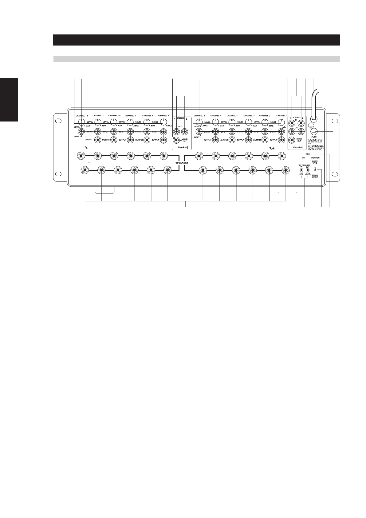
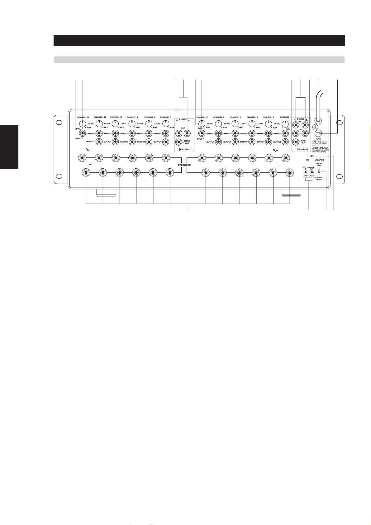
REAR-PANEL CONTROLS AND CONNECTIONS
12 3 4 12 3 5 410 11
NEDERLANDS
ESPAÑOL
ITALIANO
PORTUGUÊS
SVENSKA
9876
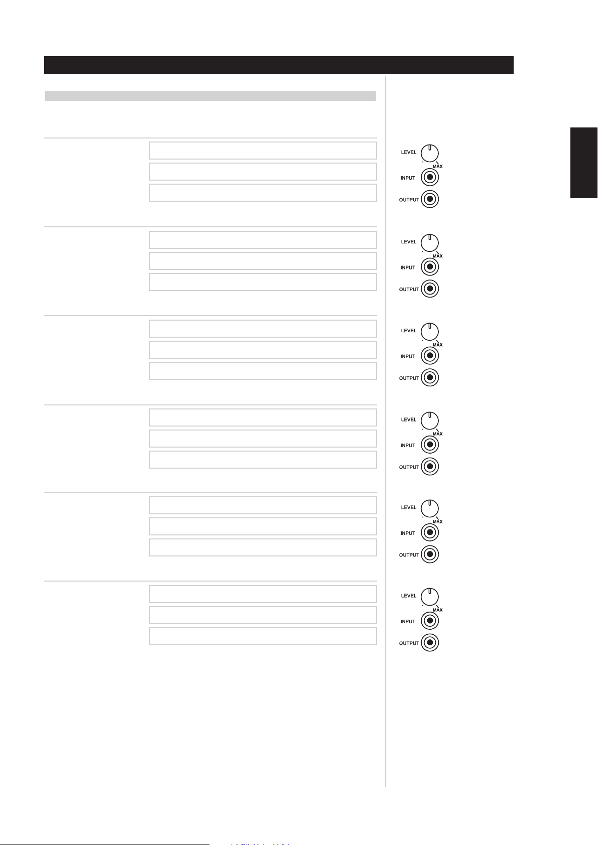
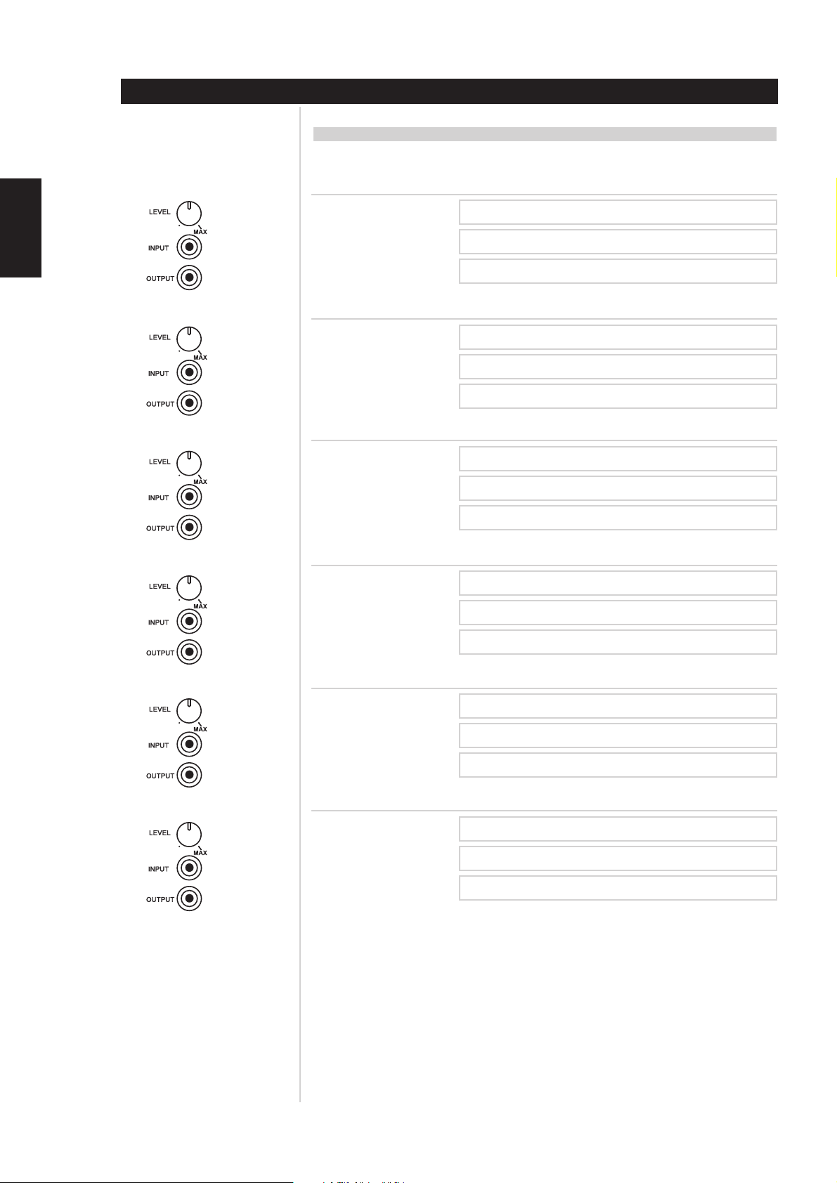
1 There is one CHANNEL trimmer per amplifier channel. Each trimmer
will attenuate each input from a minimum to MAX setting (approx 13 dB to 0.0 dB). We have designed the adjustment range sufficient
to match the speaker sensitivity both from room-to-room and per
speaker for multi-speaker installations. The design of this trimmer is
for sensitivity matching only, not a volume control. It is highly
unlikely one would adjust the trimmers once the installation was
complete, thus for this reason we have placed the trimmers at the
back of the amplifier.
2 Each amplifier CHANNEL INPUT OUTPUT is a direct pass-through
connection, thus the source impedance of each channel input is
exactly the impedance of the output. The special design of the NAD
RCA cables that accompany the NAD CI-series amplifier allow for up
to 6 channels to be fed from one channel of the Flex-Pad STEREO
and MONO OUT, without degradation in sound quality. For
example, one can jumper from Flex-Pad OUT Right to CHANNEL 1
INPUT, then from CHANNEL 1 OUTPUT to CHANNEL 2 INPUT,
from CHANNEL 2 OUTPUT to CHANNEL 3 INPUT, and so on up to
6 channels of inputs. The NAD CI-series RCA jumper cables are
specially designed low-capacitance high-performance cables. We do
not recommend that you use any other RCA jumper cables
than the NAD RCA jumper cables supplied with the NAD CIseries amplifier, to do so may cause significant loss in music
fidelity or possible other problems.
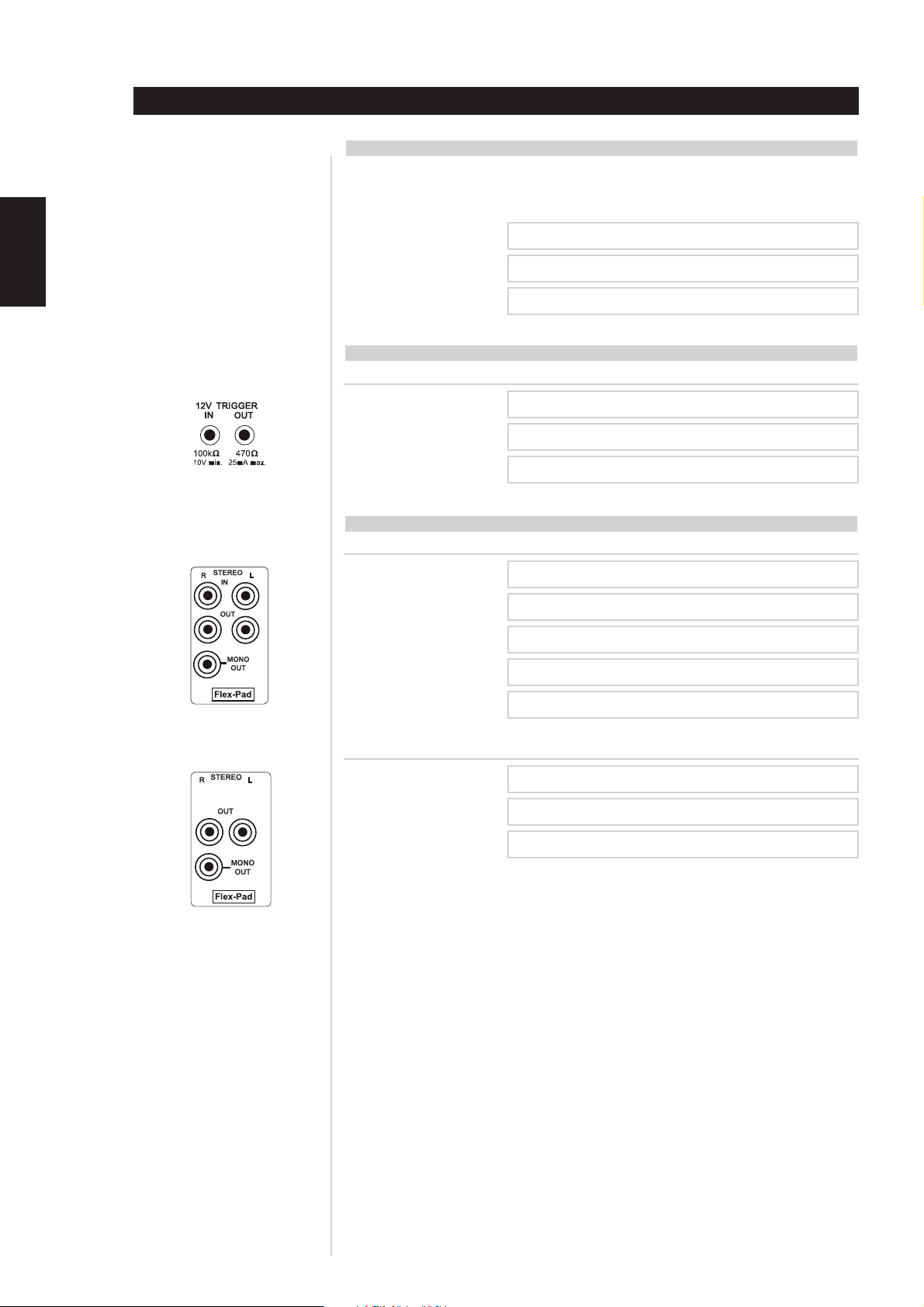
3 The Flex-Pad MONO OUT is a sum of the stereo right and left inputs
with an output impedance of 75 ohms. We do not recommend
driving more than 6 amplifier inputs with this MONO OUT source.
5 The Flex-Pad STEREO right and left IN is a high-impedance input
specifically designed for connection to preamplifier or home-theatre
processor outputs. We strongly recommend that these inputs not
be connected to equipment that does not have a volume control!
6 The VACATION switch is the master on/off control for the amplifier.
When the switch is in the on state the amplifier is in standby as shown
by the amber LED above the power switch on the front panel. If the
amplifier will not be used for an extended period of time, switch the
VACATION switch to the VACATION position.
7 The SLEEP/WAKE, SENSE/DEFEAT switch logic controls the
standby/on-state of the amplifier via the presences or absence of
audio signal at the Flex-Pad or amplifier channel inputs. The
SLEEP/WAKE, SENSE/DEFEAT switch must be in the SLEEP/WAKE
position in order to use this logic. When the SLEEP/WAKE,
SENSE/DEFEAT switch is in the SENSE/DEFEAT position, this logic
control is deactivated.
When the switch is in the SLEEP/WAKE position, the NAD CI-series
amplifier will instantaneously turn on from a standby state, sensing
any input signal from any channel as seen by a lit green SENSE LED
on the front panel of the amplifier (approximately above 20mV RMS
input). If all of the audio signals are absent for approximately 5
minutes, the amplifier will switch automatically to standby condition,
with the green SENSE LED off, and the amber LED over the front
panel switch lit.
When the switch is in the SENSE/DEFEAT position, the amplifier will not
turn on even if an input signal is present on any channel or Flex-Pad input.
4 The Flex-Pad STEREO right and left OUT is a stereo buffer with an
output impedance of 75 Ohms per output, capable of driving up to 6
NAD CI-series amplifier inputs per output. We do not recommend
you drive more than 6 amplifier inputs per Flex-Pad output.
8
Page 9

8 The 12V TRIGGER IN and OUT connectors are 3.5mm monotype
miniature phone jacks, with the centre pin of each serving respectively
as a 12V signal sensor and 12V signal driver. We recommend that you
use a good quality cable with shield when attaching the 3.5mm
monotype plugs so as to prevent false triggering of the amplifier due
to electro-magnetic interference from nearby electronic equipment.
The 12V-IN TRIGGER allows you to have an external 12V signal turn
on the NAD CI-series amplifier from standby. This 12V signal must be
a continuous 12V signal in order to keep the amplifier in the on state.
Once you remove the 12V signal the amplifier will return to standby.
The 12V-OUT TRIGGER allows you to control other products with a
12V sensor, by the NAD CI-series amplifier. The 12V-OUT TRIGGER
is constantly present when the NAD CI-series amplifier is in the on
state, and absent when in standby or VACATION state.
NOTES
• Check the specifications of the trigger input terminal on the other
components to ensure these are compatible with the NAD CI-series
amplifiers.
• All 12V-TRIGGER inputs and outputs on other NAD components
with a 12V-TRIGGER feature are fully compatible with the NAD
CI–series amplifier’s IN/OUT 12V-TRIGGER.
• Before making any connections to any 12V-TRIGGER input or output,
make sure all components are disconnected from the AC mains.
• If in doubt over the connections, installation and/or operation of the
IN/OUT 12V-TRIGGER connections consult your NAD dealer or sales
representative.
• Failure to observe the above may result in damage to the NAD CIseries amplifier and/or any ancillary components attached to it.
Operation
ENGLISH
FRANÇAISDEUTSCHNEDERLANDSESPAÑOL
9 There is one set of speaker terminals per amplifier channel. They are
marked “+” and “-” to indicate their polarity.
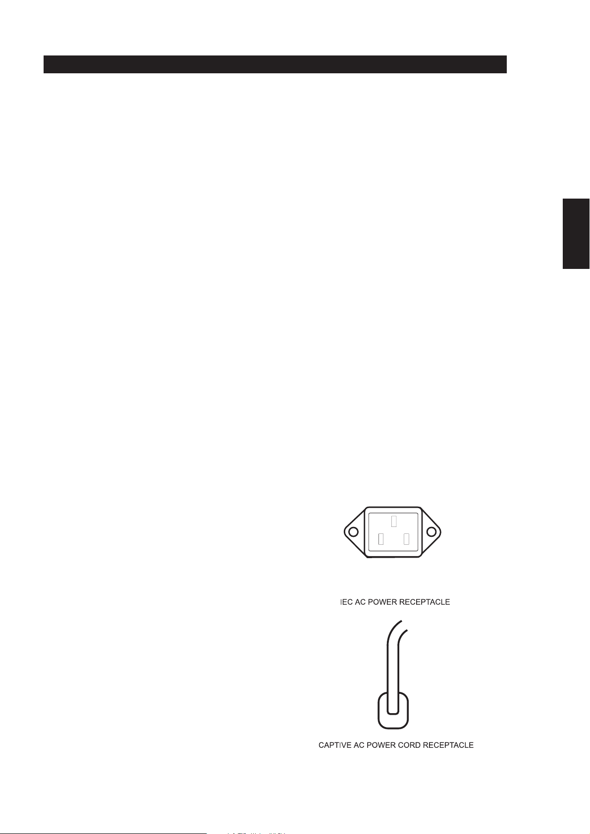
10 There are two discrete-types of AC-power cords. Refer to figures
below for the type that relates to your NAD CI-series amplifier:
Before connecting the AC-power cord to a live wall socket insure that
all inputs/outputs are connected first. Always disconnect the ACpower cord plug from the live wall socket first, before disconnecting
any cable from the CI-series amplifier. If you must use an extension
cord, select a heavy-duty cord of the type used for large electrical
appliances, such as an air conditioner AC-extension cord (16 AWG).
We strongly recommend that you not connect the amplifier’s mains
cable to the accessory AC outlets on a preamplifier. Such convenience
outlets are not designed to supply the high-power levels that the NAD
CI-series amplifier requires.
11 There is a fuse holder nearby or next to the AC-line cord. In the
unlikely event a fuse may need to be replaced, unplug the line cord
form the wall. Then remove all connections from the amplifier. Only
replace the fuse with the same type, size, and specification. Refer to
“SPECIFICATIONS, NAD Models CI 9060 and CI 9120” at the back of
this instruction manual for the correct number, type and size of the
replacement fuse.
CAUTION
Failure to replace the fuse with the correct number, brand
name, and type listed in the “FUSE REPLACEMENT - PLEASE
NOTE CAREFULLY” chart, found in the back of this instruction
manual under section “Fuse Replacement Chart” will eventually
lead to either another blown fuse or amplifier damage.
ITALIANO
PORTUGUÊS
SVENSKA
9
Page 10
ENGLISH FRANÇAIS
Operation
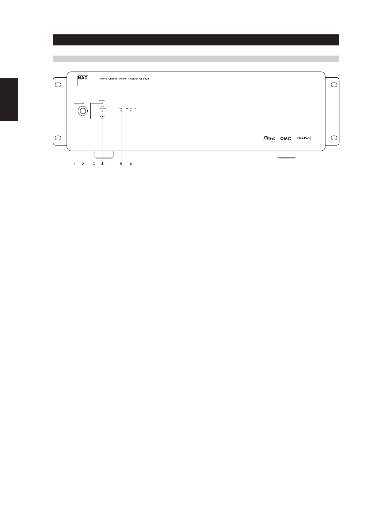
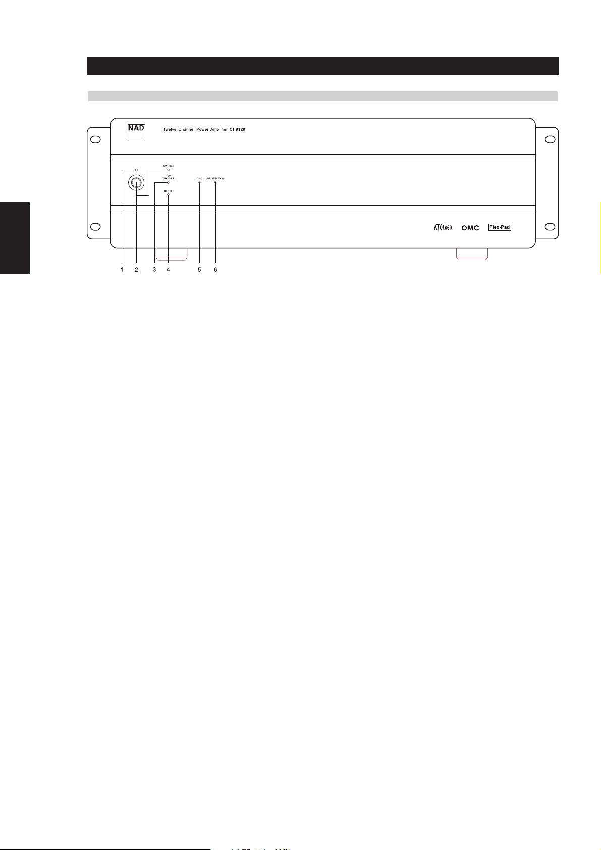
FRONT-PANEL CONTROLS AND INDICATORS
DEUTSCH
NEDERLANDS
ESPAÑOL
ITALIANO
1 The amber standby indicator LED over the front power switch must
be on for the amplifier’s ATO Logic to function. This is achieved by
having the “VACATION switch” in the ON position (refer to “Rear-
Panel Controls and Connections”: VACATION switch section).
2 The front-panel momentary-contact switch will power on, and place
into standby, the NAD CI-series amplifier, denoted by the green LED
labelled SWITCH. If you power on the amplifier via the front panel
switch, the amber standby LED will turn off, and the SWITCH LED will
turn green. Once you turn on the amplifier via the front-panel switch,
only the front-panel switch can return the amplifier to standby state.
3 The 12V-TRIGGER LED illuminates green when the amplifier switches
from standby to power on state via the 12V input (refer to “RearPanel Controls and Connections”: 12V-TRIGGER INPUT section).
Once you turn on the amplifier via the 12V-IN TRIGGER, only the
absence of the 12V can return the amplifier to standby state.
4 The SENSE LED illuminates green when the amplifier senses a signal
greater than 20mV RMS on any of the amplifier inputs refer to “RearPanel Controls and Connections”: SLEEP/WAKE, SENSE/DEFEAT
section). Once you turn on the amplifier via the SLEEP/WAKE sense
logic, only the absence of a signal to all the amplifier’s inputs can
return the amplifier to standby state.
5 The OMC LED illuminates amber when the amplifier senses too much
input signal or the load impedance drops below 2 to 3 Ohms, in either
case a potential fault condition. When the fault condition is removed,
the OMC LED will turn off, and the amplifier will return to normal
operation.
6 The PROTECTION LED illuminates red when the amplifier protects
itself. For example, in the unlikely event of overheating, protection
would be active and the protection LED would light red. The amplifier
will stay in this state until one removes the fault condition. Once you
remove the fault condition, the amplifier will come out of the
protection state, and the amplifier will return to normal operation.
PORTUGUÊS
SVENSKA
10
Page 11
RACK-MOUNT INSTALLATION
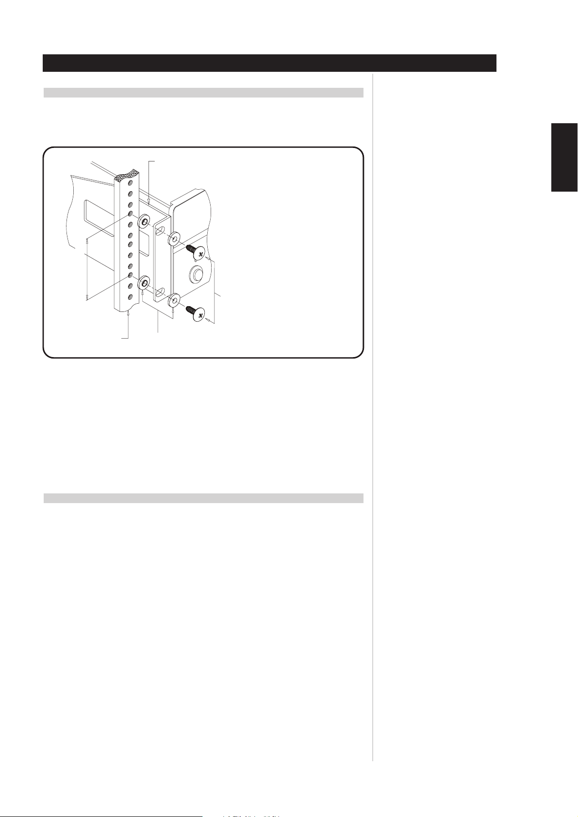
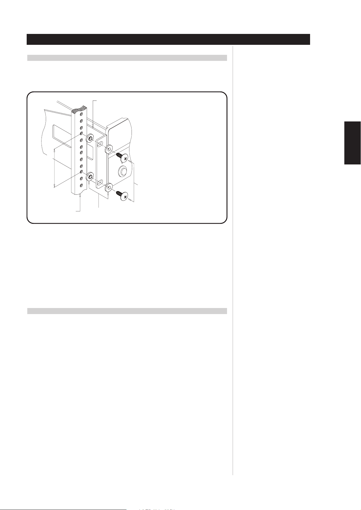
Instructions for installation of the NAD CI-series amplifier are supplied with the Rack-Mounting hardware.
Supplied with these instructions are 8 pieces of plastic bushings and 4 #10-32 bolts. These bolts with
specifically designed plastic bushings are engineered to prevent ground loops and will support the weight
of the NAD CI-series amplifier (see Figure 1).
Rack-mount bracket
(Left)
89.0mm 3U mounting rail hole
These shoulder washers are for use to rack-mount
this unit.
If properly installed (See diagram), the washers will
insulate the amplifier from the rack, preventing
ground loops and hum, and will protect the unit’s
surface from damage.
#10-32UNF-3A screw
4pcs required per unit
Installation
ENGLISH
FRANÇAISDEUTSCHNEDERLANDSESPAÑOL
Mounting rack rail
EIA standard RS-310-C
Shoulder washers
8pcs required per unit
Figure 1
Since the NAD CI-series amplifier is a heavy amplifier, we recommend that you mount the NAD CI amplifier
as close to the bottom of a rack as possible to promote a stable Rack-Mount installation.
The NAD CI-series amplifier takes up 3 standard, rack places on an EIA/IEC 19-inch rack. The NAD CI-series
amplifier needs special consideration when rack-mounting to allow sufficient ventilation space all around
the amplifier. Thus we recommend one should allow at least a one-rack-space below and above the
amplifier as clearance, and that you allow more than 2 to 3 inches (5 to 7.5 cm) of space on all six sides
of the NAD CI-series amplifier. Please refer to the “Ventilation Air Flow” specification found at the back
of the instruction manual for maximum airflow requirements.
SHELF-MOUNT INSTALLATION
REMOVAL OF RACK-MOUNT BRACKETS
This unit may be installed on any level surface that is strong enough to support the amplifier’s weight.
Please refer to the “Specifications” section at the back of the instruction manual for the exact weight of
your NAD CI-series amplifier. Since the NAD CI-series amplifier was shipped with Rack-Mounting hardware
attached, below is the removal procedure of the rack-mounting shelf brackets. We strongly recommend
that you follow these procedures in order to prevent damage to the NAD CI amplifier or personal injury:
To detach the rack-mount bracket, place the amplifier on a flat surface, remove each set of three
fixing screws on each side. Once the screws are removed, slide the bracket toward the rear of
the amplifier to release it from its fittings in the chassis bottom surface and then slide the
bracket toward you.
ITALIANO
PORTUGUÊS
For self-mount installations of the NAD CI-series amplifier, we recommend that you do not place
equipment on top of the amplifier. Leave at least 2 to 3 inches (5 to 7.5 cm) on all sides of the amplifier
so that the NAD CI-series amplifier achieves adequate airflow. We strongly recommend that you do not
block the side, top, back and front, airflow vents. Since its power transformer generates a significant
magnetic hum field, a turntable (especially one with a magnetic pick-up cartridge) or a television should
not be located adjacent to, directly above, or below the amplifier.
SVENSKA
11
Page 12
ENGLISH FRANÇAIS
DEUTSCH
NEDERLANDS
Installation
SPEAKER HOOK-UP
This amplifier is equipped with special high-current, binding-post speaker terminals to handle the highest
peak-power levels that may occur with low-impedance speakers. At moments when the amplifier is
producing maximum power, voltages of nearly 100V may be present on the speaker terminals, so plastic
covers protect the terminals. To connect loudspeaker cables, first switch off the amplifier’s power by
disconnecting the AC-power cord from the wall outlet.
Connect the wires from one of your speakers to the “+” and “-” terminals on the rear panel of the NAD
CI-series amplifier. In each channel, the red terminal is the positive “+” output, and the black terminal is
the negative “-” or “ground” terminal (see Figure 2).
Use heavy-duty (16-gauge/2mm or thicker) wire, especially with 4-ohm loudspeakers. Bare wires can be
connected directly to the binding-post terminals. For a longer lasting and more corrosion resistant
connection, you may install speaker cables with gold-plated connectors (pin connectors or spade lugs), or
you can install such connectors on the wires yourself. Connections to each binding post may be made in
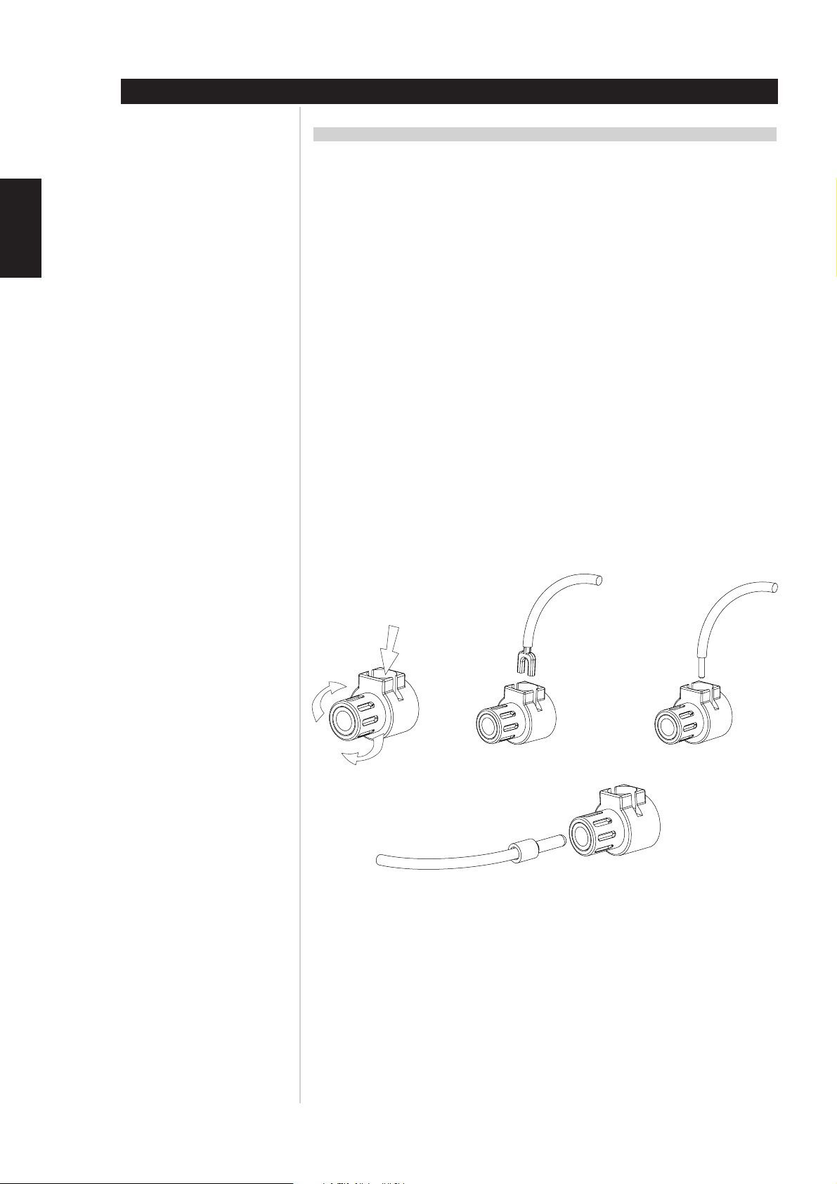
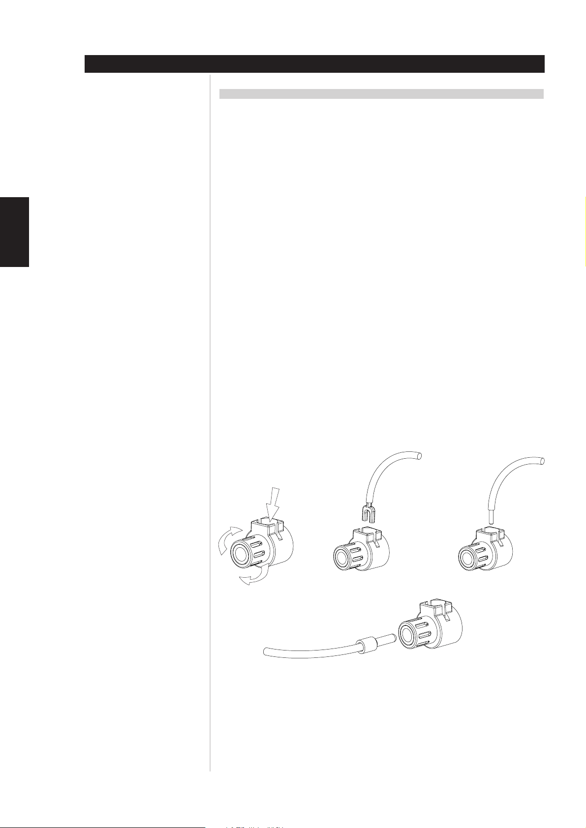
the three ways described below.
1 Pin connectors: A pin connector is a slim metal shaft that is crimped or soldered onto the end of a wire.
The threaded shaft of each binding post contains an opening that accepts pin connectors up to 3mm
in diameter. Unscrew the plastic bushing on each terminal to expose the hole in the metal shaft. Insert
the pin connector through the hole, and turn the bushing clockwise until it is tight (see Figure 2).
2 Spade lugs: Unscrew the plastic bushing, insert the U-shaped spade lug into the oblong gap and
tighten the bushing down on it (see Figure 2).
3 Bare wires: Separate the two conductors of the cord (if they are supplied as a pair), and strip off a half-
inch (1cm) of insulation from each. In each conductor, twist together the exposed wire strands.
Unscrew the plastic bushings for “+” and “-”, insert the bare wire through the hole in the metal shaft,
and tighten the plastic bushing until it grasps the wire securely (see Figure 2). Check to be sure that no
loose strand of wire is touching the chassis or an adjacent terminal. Re-tighten the bushing after a
week or so to make sure that any play that may have developed is eliminated.
ESPAÑOL
ITALIANO
PORTUGUÊS
SVENSKA
Spade Wire
Pin
Figure 2
12
Page 13

PHASING
Stereo speakers must operate “in phase” with each other to produce a focused stereo blend and to
reinforce rather than cancel each other’s output at low frequencies. An in-phase connection is assured if
the red (positive) terminal on the amplifier is connected to the red (positive) terminal on the loudspeaker
in each channel. If your speakers are easily moved, their phasing can easily be checked. Make the
connections to both speakers, place the speakers face-to-face only a few inches apart, play some music,
and listen. Then swap the connection of the two wires at the back of ONE of the speakers, and listen again.
The connection that produces the fullest, most extended bass output is the correct one. Once you have
determined the correct phasing, connect the wires securely to the speaker terminals, being careful not to
leave any loose strands of wire that might touch the wrong terminal and create a partial short-circuit, then
move the speakers to their intended locations.
If the speakers cannot easily be placed face-to-face, then phasing must rely on the “polarity” of the
connecting wires. The speaker terminals on the amplifier are identified as red “+” and black “-” in each
channel. The terminals at the rear of the speakers are also marked for polarity, either via red and black
connectors or by labels: “+”, “1”, or “8 ohms” for positive, “-”, “0”, or “G” for negative. The red “+”
terminal on the amplifier should be connected to the red (positive) terminal of the speaker in each channel.
To facilitate this, the two conductors comprising the speaker wire in each channel are different, either in
the colour of the wire itself (copper vs. silver) or in the presence of a small ridge or rib-pattern on the
insulation of one conductor. Use this pattern to establish consistent wiring to both speakers of a stereo
pair. Thus if you connect the copper-coloured wire (or ribbed insulation) to the “+” amplifier terminal in
the Left channel, do the same in the Right channel. At the other end of the wire, if you connect the coppercoloured wire (or the ribbed insulation) to the red (positive) terminal on the left channel speaker, do the
same at the right channel speaker.
Installation
ENGLISH
FRANÇAISDEUTSCHNEDERLANDSESPAÑOL
NOTE
Safety organizations recommend that the speaker terminals of a very powerful amplifier should be
covered. Potentially dangerous voltages are present on these terminals when the amplifier is producing
maximum power. For your protection and in order to comply with these regulations, we have chosen
speaker terminals of the very highest quality for the NAD CI-series amplifier. These terminals are
covered by plastic bushings, which prevent the touching of metal parts.
ITALIANO
PORTUGUÊS
13
SVENSKA
Page 14
ENGLISH FRANÇAIS
Installation
ATTENTION INSTALLATION PERSONNEL
The following charts should be completely filled out and left in the possession of the NAD CI-series
amplifier’s owner, to be used for future referral. Record all speaker locations, zones, controls, sources, and
individual amplifier level settings.
NAD MODEL NUMBER
NUMBER of ZONES per AMPLIFIER
DEUTSCH
NEDERLANDS
ESPAÑOL
LOCATION of NAD CI-SERIES
AMPLIFIER
AMPLIFIER POWER CONTROL
SOURCE & DESCRIPTION OF POWER CONTROL
SOURCE FOR 12V-TRIGGER
EQUIPMENT FED BY NAD CI
SOURCE FOR SIGNAL SENSE
12V–TRIGGER
CLIENT CONFIGURATION
FLEX-PAD FOR THE FIRST 6 CHANNELS
SOURCE L
SOURCE R
DESTINATION L
DESTINATION R
DESTINATION MONO
ITALIANO
PORTUGUÊS
SVENSKA
FLEX-PAD FOR THE SECOND 6 CHANNELS
DESTINATION L
DESTINATION R
DESTINATION MONO
14
Page 15
CLIENT CONFIGURATION (INPUT/CHANNEL DESTINATION)
MARK OFF INDIVIDUAL AMPLIFIER LEVEL SETTING FOR EACH CHANNEL BELOW
CHANNEL 1
SOURCE
ROOM LOCATION
SPEAKER DESCRIPTION
CHANNEL 2
SOURCE
Installation
ENGLISH
SPEAKER DESCRIPTION
CHANNEL 3
SPEAKER DESCRIPTION
CHANNEL 4
SPEAKER DESCRIPTION
CHANNEL 5
SPEAKER DESCRIPTION
ROOM LOCATION
SOURCE
ROOM LOCATION
SOURCE
ROOM LOCATION
SOURCE
ROOM LOCATION
FRANÇAISDEUTSCHNEDERLANDSESPAÑOL
ITALIANO
CHANNEL 6
SPEAKER DESCRIPTION
SOURCE
ROOM LOCATION
PORTUGUÊS
SVENSKA
15
Page 16
Installation
CLIENT CONFIGURATION (INPUT/CHANNEL DESTINATION CONTINUED)
MARK OFF INDIVIDUAL AMPLIFIER LEVEL SETTINGS FOR EACH CHANNEL BELOW:
ENGLISH FRANÇAIS
DEUTSCH
NEDERLANDS
CHANNEL 7
SOURCE
ROOM LOCATION
SPEAKER DESCRIPTION
CHANNEL 8
SOURCE
ROOM LOCATION
SPEAKER DESCRIPTION
CHANNEL 9
SOURCE
ROOM LOCATION
SPEAKER DESCRIPTION
CHANNEL 10
SOURCE
ESPAÑOL
ITALIANO
PORTUGUÊS
SVENSKA
ROOM LOCATION
SPEAKER DESCRIPTION
CHANNEL 11
SOURCE
ROOM LOCATION
SPEAKER DESCRIPTION
CHANNEL 12
SOURCE
ROOM LOCATION
SPEAKER DESCRIPTION
16
Page 17

Troubleshooting
PROBLEM CAUSE SOLUTION
No sound
No sound in one channel
Weak bass/ poor stereo image
Low or distorted sound in one zone/room
and OMC LED on
• Power AC-mains cable unplugged
• VACATION switch set to VACATION
• The Protection mode is engaged
• External fuse blown
• Speaker not properly connected or damaged
• Input cable pulled loose or making poor contact
at Flex-Pad socket
• Short-circuit or broken wire in a defective patch
or speaker cable
• Speakers wired out-of-phase • Reverse connections at the back of the suspect
• Shorted speaker cable to zone/room
•Too high of an input level to one or more
amplifier channels
•Too low an impedance on one or more amplifier
zones/rooms
• Check if AC-mains cable is plugged in and
power switched on
• Set the VACATION switch to ON
•Switch amplifier off via VACATION switch. Make
sure ventilation slots on top, side, and back of the
amplifier are not blocked. After amplifier has
cooled down, switch the amplifier on
• Replace fuse
• Consult dealer/installer
• Check all connections both at the speakers and
at the amplifier
•Check leads and Flex-Pad cables
• Switch the amplifier to VACATION mode, check
and replace cables if necessary
amplifier output
• Check connections to all speakers in the affected
zone/room
• Switch off amplifier via VACATION switch and
remove one at a time a pair of speaker cables
from the amplifier, then switch the VACATION
switch to the ON position and restore audio
source. Continue this procedure until the OMC
LED does not turn on. Replace the shorted
speaker cable to the zone/room
•Turn down the input level to the room/zone that
may be suspect
•Too many speakers connected to one channel, or
incorrect speaker pad or matching transformer
impedance settings. Remove some speakers or
check speaker pad and/or documentation
supplied from the speaker pad manufacturer for
correct impedance settings
• Damage to speaker pad. Replace speaker pad
ENGLISH
FRANÇAISDEUTSCHNEDERLANDSESPAÑOL
17
ITALIANO
PORTUGUÊS
SVENSKA
Page 18

ENGLISH FRANÇAIS
DEUTSCH
NEDERLANDS
ESPAÑOL
ITALIANO
Specifications
Power Rating
85 Watts continuous average power into 6 Ohms at any frequency between 20Hz and 20kHz
with all channels driven at less than 0.03% THD.
86 Watts continuous average power into 4 Ohms at any frequency between 20Hz and 20kHz
with all channels driven at less than 0.03% THD.
IM Distortion (SMPTE)
80 Watts into 6 Ohms < 0.03 %
80 Watts into 4 Ohms < 0.03 %
IM Distortion (CCIF, Any Combination from 1kHz to 20kHz)
80 Watts into 6 Ohms < 0.03 %
80 Watts into 4 Ohms < 0.03 %
THD + Noise at 1 Watt into 6 Ohms
20Hz 0.03 %
1kHz 0.03 %
10kHz 0.03 %
20kHz 0.03 %
THD + Noise at 80 Watts into 6 Ohms
20Hz 0.03 %
1kHz 0.03 %
10kHz 0.03 %
20kHz 0.03 %
Frequency Response @ 1 Watt into 6 Ohms
10Hz to 20kHz + 0.5, -1.0dB
Power Bandwidth (-3dB) 5Hz to 45kHz
Gain 28dB
Amplifier Trimmer Adjustment Range 14 ± 2 dB
Damping Factor >30
Dynamic Headroom into 6 Ohms 1.6dB
OMC Activation < 3 Ohms across any speaker terminal
ATO Logic
SENSE Input Sensitivity >20mV rms
12V Trigger Input Voltage Range 10.0V to 20.0V DC, 100k Ohms
12V Trigger Output Current 25 ± 5mA, 470 Ohms
Input Impedance 25k Ohms
Input Sensitivity
80 Watt into 6 Ohms 1V rms
1 Watt into 6 Ohms 114mV rms
Damping Factor 20Hz to 20kHz < 31
Rise Time
5kHz, 50V peak-to-peak square wave,
20% to 80% 4 µs
PORTUGUÊS
SVENSKA
Power Consumption (Continuous, All Channels Driven)
Quiescent 84/168VA
Maximum 960/1920VA
80 Watts into 6 Ohms 744/1488VA
80 Watts into 4 Ohms 900/1800VA
GENERAL
Power (available in 240V) 120VAC/50-60Hz
Ambient Operating Temperature < 100 °F (40 °C)
Operating Temperature 68 °F (20 °C)
above ambient temperature
Ventilation Air Flow 150 cubic feet/minute maximum
Net Chassis Dimensions 17.2x5.3x17.8 inches (437x133x451 mm)
or 3 rack heights
Maximum Gross Dimensions 18.9x19.0x5.7 inches (480.1x481.7x144.8 mm)
(includes rack mounting hardware,
feet and speaker terminals)
Weight CI 9060, Packed 55-60 lb (25-27 Kg), 75 lb (34 Kg)
Weight CI 9120, Packed 78-82 (35-37 Kg), 97 lb (44 Kg)
18
Page 19

Fuse Replacement Chart
FUSE REPLACEMENT - PLEASE NOTE CAREFULLY
The fuses listed in the chart below have been carefully selected and thoroughly tested to deliver optimal
performance and still accomplish their protective functions. Replace the AC INPUT LINE FUSE only with
one of the fuses listed in the chart. DO NOT USE ANY SUBSTITUTE FUSES OF DIFFERENT TYPES OR
WITH DIFFERENT CURRENT RATINGS, TIME-CURRENT CURVES OR VALUES. Failure to observe this
precaution may cause damage to the amplifier circuits, MAY CREATE A FIRE HAZARD AND/OR DEFEAT
THE SAFETIES BUILT INTO THE AMPLIFIER, AND MAY VOID THE WARRANTY.
Model Bussman Littelfuse Bel
9120 AH MDA-20/250V 3AB 326020/250V N/A
9060 AH MDA-12/250V 3AB 326012/250V GSA 12/250
9120 C (1 & 2) MDA-10/250V 3AB 326010/250V GSA 10/250
9060 C (1 & 2) MDA-6/250V 3AB 326060/250V GSA 6/250
ENGLISH
FRANÇAISDEUTSCHNEDERLANDSESPAÑOL
19
ITALIANO
PORTUGUÊS
SVENSKA
Page 20

ENGLISH FRANÇAIS
DEUTSCH
NEDERLANDS
ESPAÑOL
ITALIANO
PORTUGUÊS
SVENSKA
2
Page 21

TABLE DES MATIÈRES
I Introduction . . . . . . . . . . . . . . . . . . . . . . . . . . . . . . . . . . . . . . . . . . . . . . . . . . . . . . . . . . . . . . .3-5
Consignes de Sécurité. . . . . . . . . . . . . . . . . . . . . . . . . . . . . . . . . . . . . . . . . . . . . . . . . . . . . . . . . 4
II Fonctionnement . . . . . . . . . . . . . . . . . . . . . . . . . . . . . . . . . . . . . . . . . . . . . . . . . . . . . . . . . .6-10
ATO Logic de NAD . . . . . . . . . . . . . . . . . . . . . . . . . . . . . . . . . . . . . . . . . . . . . . . . . . . . . . . . . . . 6
OMC de NAD. . . . . . . . . . . . . . . . . . . . . . . . . . . . . . . . . . . . . . . . . . . . . . . . . . . . . . . . . . . . . . . 7
Circuits de protection NAD . . . . . . . . . . . . . . . . . . . . . . . . . . . . . . . . . . . . . . . . . . . . . . . . . . . . . 7
III Installation . . . . . . . . . . . . . . . . . . . . . . . . . . . . . . . . . . . . . . . . . . . . . . . . . . . . . . . . . . . . .11-16
Montage en Châssis-Rack . . . . . . . . . . . . . . . . . . . . . . . . . . . . . . . . . . . . . . . . . . . . . . . . . . . . . 11
Montage sur Étagère . . . . . . . . . . . . . . . . . . . . . . . . . . . . . . . . . . . . . . . . . . . . . . . . . . . . . . . . 11
Branchement des haut-parleurs. . . . . . . . . . . . . . . . . . . . . . . . . . . . . . . . . . . . . . . . . . . . . . . . . 12
Configuration spécifique au client (entrée / destination des voies). . . . . . . . . . . . . . . . . . . . . . . . 14
Configuration spécifique au client (Flex-Pad) . . . . . . . . . . . . . . . . . . . . . . . . . . . . . . . . . . . . . . . 15
IV Dépannage . . . . . . . . . . . . . . . . . . . . . . . . . . . . . . . . . . . . . . . . . . . . . . . . . . . . . . . . . . . . . . .17
V Caractéristiques . . . . . . . . . . . . . . . . . . . . . . . . . . . . . . . . . . . . . . . . . . . . . . . . . . . . . . . . . . . .18
VI Tableau de remplacement des fusibles . . . . . . . . . . . . . . . . . . . . . . . . . . . . . . . . . . . . . . . . .19
ATTENTION : PERSONNEL D’INSTALLATION
Le matériel de fixation a été spécialement conçu pour l’Amplificateur NAD série CI. Nous déconseillons
l’utilisation d’un autre type de matériel de fixation.
L’amplificateur NAD série CI étant d’une très grande puissance, les blocs d’alimentation sont lourds et
plusieurs personnes seront peut-être nécessaires pour monter l’ensemble de l’amplificateur dans un
châssis-rack.
Introduction
ENGLISH
FRANÇAISDEUTSCHNEDERLANDSESPAÑOL
NOTA
Lorsque l’amplificateur est posé sur une surface horizontale, sa masse doit toujours reposer sur ses
pieds inférieurs. Il ne faut jamais poser l’amplificateur sur son panneau arrière, face parlante vers le
haut. Si vous le faites, vous risquez d’endommager les connecteurs d’entrée-sortie.
L’amplificateur génère une quantité modérée de chaleur et nécessite donc une ventilation interne. Veillez
donc à ce que les grilles d’entrée et de sortie d’air situées sur les panneaux supérieur, inférieur, latéraux et
arrière, ne soient jamais obstruées par des papiers ou par tout autre objet.
NOTA
Pour éviter tout risque d’incendie ou de choc électrique, évitez toute pénétration de liquide ou
d’humidité à l’intérieur de l’amplificateur. En cas de déversement accidentel d’un liquide dans l’appareil,
coupez immédiatement l’alimentation électrique et débranchez le câble secteur de la prise murale.
N’ouvrez pas l’amplificateur et ne tentez jamais de le modifier ou de le réparer vous-même. Pour toute
intervention, adressez-vous à un technicien qualifié.
ITALIANO
PORTUGUÊS
Les caractéristiques ou la conception de ce matériel peuvent être modifiées sans préavis. Toutes les
caractéristiques indiquées sont celles de l’appareil au moment de l’impression du présent document.
NAD®, OMC™, ATO Logic™, et Flex-Pad™ sont des marques déposées de NAD Electronics International,
division de Lenbrook Industries Limited.
©2000, NAD Electronics International, division de Lenbrook Industries Limited
SVENSKA
3
Page 22

ENGLISH FRANÇAIS
DEUTSCH
NEDERLANDS
ESPAÑOL
Introduction
EXPLICATION DES SYMBOLES GRAPHIQUES
Le symbole de l'éclair avec une flèche à son extrémité, dans un triangle équilatéral, a pour but
d'avertir l'utilisateur de la présence d'une "tension électrique dangereuse" à l'intérieur de
l'enceinte de l'appareil, qui peut être suffisamment puissante pour constituer un risque de choc
électrique pour les personnes.
Le point d'exclamation dans un triangle équilatéral a pour but d'avertir l'utilisateur que la
documentation livrée avec l'appareil contient des instructions importantes concernant
l'utilisation et l'entretien.
PRÉCAUTIONS
Lisez attentivement l'ensemble des Instructions d'Utilisation avant de faire fonctionner l'appareil.
Conservez les Instructions d'Utilisation afin de pouvoir vous y référer à une date ultérieure. Tous les
avertissements et toutes les mises en garde imprimés dans les Instructions d'Utilisation et sur l'appareil luimême doivent être respectés. Il en est de même pour les recommandations suivantes concernant la
sécurité.
INSTALLATION
1 Eau et Humidité - Cet appareil ne doit pas être utilisé à proximité de l'eau, par exemple près d'une
baignoire, d'un lavabo, d'une piscine, etc ...
2 Chaleur - N'utilisez pas cet appareil à proximité d'une source de chaleur comme une bouche de
chauffage, une cuisinière ou tout autre appareil dégageant de la chaleur. L'appareil ne doit pas être mis
en présence de températures inférieures à 5 °C ou supérieures à 35 °C.
3 Support - Posez l'appareil sur une surface plane et horizontale.
4 Aération - L'appareil doit être installé dans un endroit où l'air peut circuler librement autour, afin de
bien évacuer la chaleur dégagée. Prévoyez un dégagement de 10 cm derrière et au dessus de l'appareil
et de 5 cm de chaque côté. - Ne posez pas l'appareil sur un lit, un tapis ou une surface semblable, car
cela boucherait les ouvertures d'aération sur la face inférieure. - N'installez pas l'appareil dans une
bibliothèque fermée ou dans un rack hermétique, car la ventilation de l'appareil ne serait pas assurée
correctement.
5 Pénétration de corps étrangers ou de liquides - Veillez à ce qu'aucun objet ni aucun liquide ne
pénètre à l'intérieur de l'appareil à travers les ouvertures d'aération.
6 Chariots et supports - Si vous placez ou installez l'appareil sur un support ou sur un chariot, les
déplacements doivent être effectués en faisant très attention. Les arrêts brusques, les efforts excessifs
ou les sols accidentés risqueraient de renverser le chariot et l'appareil.
7 Fixation au mur ou au plafond - L'appareil ne doit pas être fixé au mur ou au plafond, à moins que
cela ne soit prévu dans les Instructions de l'Utilisateur.
ITALIANO
PORTUGUÊS
SVENSKA
ATTENTION DANGER. POUR ÉVITER TOUT RISQUE D'INCENDIE OU DE CHOC
ÉLECTRIQUE, N'EXPOSEZ JAMAIS CET APPAREIL A LA PLUIE OU A L'HUMIDITÉ.
Ce produit a été fabriqué de manière à être conforme aux exigences concernant les interférence radio des
DIRECTIVES CEE 89/68/EEC et 73/23/EEC.
4
Page 23

ALIMENTATION ÉLECTRIQUE
1 Sources d'alimentation - Ce produit doit obligatoirement être alimenté par une source du type
indiqué dans les Instructions d'Utilisation et sur l'appareil lui-même.
2 Polarité - Pour des raisons de sécurité, il se peut que cet appareil soit équipé d'une prise secteur
alternatif avec système de détrompage interdisant tout branchement dans le "mauvais sens". Si la fiche
n'entre pas (ou pas complètement) dans la prise murale, essayez de la brancher dans l'autre sens. Si
elle n'entre toujours pas, appelez un électricien qualifié pour faire réparer ou remplacer votre prise
murale. Afin de ne pas détériorer le dispositif de sécurité de la prise détrompée, n'essayez pas de la
brancher de force dans la prise murale.
3 Cordon d'alimentation secteur - Lorsque vous débranchez le cordon d'alimentation secteur, tirez sur
la fiche secteur et non sur le cordon.
• Ne touchez jamais la fiche ou la prise secteur si vous avez les mains mouillées, car vous risqueriez
de subir un choc électrique ou de provoquer un incendie.
• Les câbles d'alimentation ne doivent pas passer dans des endroits où ils risquent d'être piétinés ou
pincés ou tordus excessivement. Faites particulièrement attention à ces détails pour ce qui concerne
le câble entre l'appareil et la prise murale.
• Évitez de surcharger les prises de secteur murales et/ou les rallonges, car cela risquerait d'entraîner
un incendie ou de provoquer un choc électrique.
4 Rallonge électrique - Afin de contribuer à éviter les chocs électriques, ne branchez jamais une fiche
secteur détrompée sur une rallonge électrique, une embase ou une quelconque autre source de
courant si la fiche ne peut pas être complètement enfoncée dans la prise : les broches de la fiche
doivent être inaccessibles.
5 Lorsque l'appareil n'est pas utilisé - Débranchez le cordon secteur de la prise murale si l'appareil ne
va pas être utilisé pendant plusieurs mois. Lorsque le cordon reste branché, un courant faible est débité
par l'appareil, même s'il est hors tension.
Introduction
ENGLISH
FRANÇAISDEUTSCHNEDERLANDSESPAÑOL
ATTENTION
En cas de réglage ou de modification dont la conformité n'aura pas été expressément approuvée par le
fabricant, le droit de l'utilisateur de faire fonctionner l'appareil risque d'être retiré.
DÉTÉRIORATIONS NÉCESSITANT UNE INTERVENTION
Dans les cas suivants, faites réparer l'appareil par un technicien de service après vente qualifié :
• Détérioration de la fiche d'alimentation secteur.
• Pénétration de corps étrangers ou de liquides à l'intérieur de l'appareil.
• L'appareil a été exposé à la pluie ou à l'humidité - L'appareil semble ne pas fonctionner
correctement.
• Les performances de l'appareil se sont sensiblement détériorées.
• L'appareil a subi une chute, ou le boîtier a été endommagé.
NE TENTEZ AUCUNE RÉPARATION VOUS-MÊME.
INFORMATIONS PARTICULIÈRES
Pour simplifier vos démarches, notez ci-dessous le numéro de modèle et le numéro de série de votre
appareil (vous les trouverez à l'arrière de l'appareil lui-même). Veuillez les rappeler lorsque vous contacterez
votre revendeur, en cas de problème.
N° de Modèle :
N° de Série :
ITALIANO
PORTUGUÊS
SVENSKA
5
Page 24

ENGLISH FRANÇAIS
DEUTSCH
NEDERLANDS
ESPAÑOL
ITALIANO
PORTUGUÊS
SVENSKA
Fonctionnement
ATO LOGIC DE NAD
La mise en marche de l’amplificateur série CI peut être effectuée de trois façons distinctes, pour une
flexibilité totale de la chaîne : 1) à l’aide de l’interrupteur de la face parlante, 2) via le circuit
d’ASSERVISSEMENT 12 V [12V-TRIGGER], ou 3) via un circuit de détection de signal VEILLE/ÉVEIL
[SLEEP/WAKE]. La commande MARCHE/ARRÊT [ON/OFF] est gérée par le circuit Logique de Mise en
Marche Automatique [Automated Turn-On logic - ATO Logic], qui nécessite que l’on remette
l’amplificateur en mode veille en utilisant la même commande que pour sa mise en marche. Autrement
dit, si vous mettez l’amplificateur en marche grâce à un signal de commande 12 V, il est impossible de le
remettre en veille à l’aide de l’interrupteur sur la face parlante ; l’amplificateur doit obligatoirement
attendre la disparition du signal de commande 12 V. Dans la pratique, vous n’utiliserez qu’une seule de ces
trois méthodes une fois l’installation de votre amplificateur NAD série CI terminée.
TABLEAU DE LOGIQUE DE MISE EN MARCHE AUTOMATIQUE [ATO LOGIC]
LED orange au
INTERRUPTEUR [“SWITCH”]
Interrupteur VACANCES [VACATION]
en position “VACANCES”
[“VACATION”]
Interrupteur VACANCES [VACATION]
en position MARCHE [ON]
Impulsion sur le bouton interrupteur
d’alimentation sur la face parlante,
alors que l’interrupteur VACANCES
[VACATION] est en position MARCHE
[ON]
Nouvelle impulsion sur le bouton
interrupteur d’alimentation sur la face
parlante, alors que l’interrupteur
VACANCES [VACATION] est en
position MARCHE [ON]
d’ASSERVISSEMENT 12V
[12V-TRIGGER]
Interrupteur VACANCES [VACATION]
en position “VACANCES”
[“VACATION”]
Interrupteur VACANCES [VACATION]
en position MARCHE [“ON”]
ENTRÉE ASSERVISSEMENT 12 V = 0 V
avec Interrupteur VACANCES
[VACATION] en position MARCHE
[“ON”]
ENTRÉE ASSERVISSEMENT 12 V = 12
V avec Interrupteur VACANCES
[VACATION] en position MARCHE
[“ON”]
VEILLE/ÉVEIL [SLEEP/WAKE]
Interrupteur VACANCES [VACATION]
en position “VACANCES”
[“VACATION”]
Interrupteur VACANCES [VACATION]
en position “MARCHE” [“ON”]
Sélecteur VEILLE/ÉVEIL - CAPTEUR
INHIBÉ [SLEEP/WAKE - SENSE
DEFEAT] en position CAPTEUR INHIBÉ
[SENSE DEFEAT) avec interrupteur
VACANCES [VACATION] en position
“MARCHE” [“ON”]
Sélecteur VEILLE/ÉVEIL - CAPTEUR
INHIBÉ [SLEEP/WAKE - SENSE
DEFEAT] en position VEILLE/ÉVEIL
[SLEEP/WAKE] et n’importe quelle
entrée source est à plus de 20mV,
avec interrupteur VACANCES
[VACATION] en position “MARCHE”
[“ON”]
dessus de
l’interrupteur de la
face parlante
ÉTEINTE ÉTEINTE ÉTEINTE ÉTEINTE
ALLUMÉE ÉTEINTE ARRÊT ÉTEINTE
ÉTEINTE ALLUMÉE ÉTEINTE ÉTEINTE
ALLUMÉE ÉTEINTE ÉTEINTE ÉTEINTE
LED orange au
dessus de
l’interrupteur de la
face parlante
ÉTEINTE ÉTEINTE ÉTEINTE ÉTEINTE
ALLUMÉE ÉTEINTE ÉTEINTE ÉTEINTE
ALLUMÉE ÉTEINTE ÉTEINTE ÉTEINTE
ÉTEINTE ÉTEINTE ALLUMÉE ÉTEINTE
LED orange au
dessus de
l’interrupteur de la
face parlante
ÉTEINTE ÉTEINTE ÉTEINTE ÉTEINTE
ALLUMÉE ÉTEINTE ÉTEINTE ÉTEINTE
ALLUMÉE ÉTEINTE ÉTEINTE ÉTEINTE
ÉTEINTE ÉTEINTE ÉTEINTE ALLUMÉE
LED verte
INTERRUPTEUR
[“SWITCH”]
LED verte
INTERRUPTEUR
[“SWITCH”]
LED verte
INTERRUPTEUR
[“SWITCH”]
LED verte
d’ASSERVISSEMENT
12 V [12V-TRIGGER]
LED verte
d’ASSERVISSEMENT
12 V [12V-TRIGGER]
LED verte
d’ASSERVISSEMENT
12 V [12V-TRIGGER]
LED verte CAPTEUR
[SENSE]
LED verte CAPTEUR
[SENSE]
LED verte CAPTEUR
[SENSE]
6
Page 25

OMC DE NAD
Le Circuit de Gestion Sorties [Output Management Circuit (OMC)] spécifique à NAD garantit la disponibilité
de toute la puissance de l'amplificateur, quelle que soit l'impédance de charge à la sortie (dans des limites
raisonnables). L'OMC assure la commande des différentes voies de l'amplificateur en gérant le niveau
d'entrée (en cas de signal d'entrée délibérément excessif) et/ou le niveau de sortie (en cas de défaillance
au niveau du haut-parleur ou de son câble. Cela permet non seulement de protéger l'amplificateur, mais
aussi d'empêcher un échauffement excessif des charges connectées à l'amplificateur, ce qui constitue un
facteur important pour assurer la fiabilité d'une chaîne complète. Lorsque l'OMC détecte une situation de
panne potentielle et qu'il commence à limiter le débit de courant, une LED orange s'allume sur la face
parlante pour en avertir l'installateur ou le propriétaire d'un problème dans la chaîne. Lorsque l'OMC est
actif, l'amplificateur continue à fonctionner sans distorsion mais le niveau de puissance sera peut-être
réduit sur la voie affectée par le problème. Si la panne persiste et que l'impédance tombe à une valeur
insuffisante, les voies affectées activent les Circuits de Protection NAD (reportez-vous à la section
concernant les Circuits de Protection NAD, ci-après).
CIRCUITS DE PROTECTION NAD
Chaque fois que nous avons pris une décision concernant la conception de ce produit, tant électronique
que mécanique, l'objectif primaire a toujours été la fiabilité totale de l'amplificateur. Un circuit de
protection à réarmement automatique fait aussi partie de la conception de l'Amplificateur série CI. Le
circuit de protection ultrarapide s'active instantanément si l'amplificateur chauffe excessivement ou est
confronté à état de court circuit. Une LED sur la face parlante s'allume quand le circuit de Protection a été
activé. Seuls les amplificateurs affectés par un état de court-circuit seront en mode Protection ; toutes les
autres voies continueront à fonctionner normalement. Dès que les conditions normales se sont rétablies,
les voies affectées sont remises à zéro. Dans le cas peu probable d'une panne de l'amplificateur,
l'Amplificateur série CI est conçu pour permettre une réparation facile à domicile car tous les circuits
d'amplification sont montés sur des modules enfichables.
Fonctionnement
ENGLISH
FRANÇAISDEUTSCHNEDERLANDSESPAÑOL
ITALIANO
PORTUGUÊS
SVENSKA
7
Page 26
ENGLISH FRANÇAIS
DEUTSCH
NEDERLANDS
ESPAÑOL
Fonctionnement
COMMANDES ET BRANCHEMENTS SUR LE PANNEAU ARRIÈRE
12 3 4 12 3 5 410 11
1 Il existe une commande de réglage de VOIE pour chaque voie de
l’amplificateur. Chaque commande de réglage permet d’atténuer
chaque entrée depuis une valeur minimum à la valeur MAXI [MAX]
(environ -13 dB à 0.0 dB). Nous avons défini la plage de réglage de
manière à ce qu’elle soit suffisante pour accorder la sensibilité des
différents haut-parleurs, qu’ils soient répartis dans plusieurs pièces ou
installés dans la même pièce. Cette commande de réglage est conçue
uniquement pour apparier la sensibilité ; il ne s’agit pas d’une
commande de volume sonore. Il est peu probable que vous ayez à
modifier le réglage de ces commandes après avoir terminé
l’installation de votre chaîne, ce qui explique pourquoi elles se
trouvent à l’arrière de l’amplificateur.
4 Les SORTIES STÉRÉO Flex-Pad [Flex-Pad STEREO OUT] droite et
gauche constituent un tampon stéréophonique avec une impédance
de 75 Ohms par sortie, capable de piloter jusqu’à 6 entrées
d’amplificateur NAD série CI par sortie. Nous vous déconseillons de
piloter plus de 6 entrées d’amplificateur par sortie Flex-Pad.
5 Les ENTRÉES STÉRÉO Flex-Pad [Flex-Pad STEREO IN] droite et
gauche sont des entrées haute impédance spécialement conçues
pour recevoir les sorties d’un préamplificateur ou d’un processeur de
cinéma à domicile. Nous vous recommandons vivement de
connecter ces entrées à un appareil qui n’est pas doté d’une
commande de volume !
ITALIANO
PORTUGUÊS
SVENSKA
2 Chaque ENTRÉE ET SORTIE DE VOIE [CHANNEL INPUT OUTPUT] est
une connexion directe, ce qui fait que l’impédance source de chaque
entrée de voie est identique à l’impédance de la sortie. La conception
spéciale des câbles RCA de NAD, fournis avec l’amplificateur NAD série
CI, permettent d’alimenter jusqu’à 6 voies à partie d’une seule voie de
SORTIE Flex-Pad STÉRÉO et MONO, sans dégradation de la qualité
du son. À titre d’exemple, il est possible de relier la SORTIE Droite [OUT
Right] du Flex-Pad à l’ENTRÉE VOIE 1 [CHANNEL 1 INPUT], puis la
SORTIE VOIE 1 [CHANNEL 1 OUTPUT] à l’ENTRÉE VOIE 2 [CHANNEL
2 INPUT], la SORTIE VOIE 2 [CHANNEL 2 OUTPUT] à l’ENTRÉE VOIE
3 [CHANNEL 3 INPUT], et ainsi de suite jusqu’à six voies d’entrées. Les
câbles RCA NAD série CI sont des câbles hautes performances,
spécialement conçus pour avoir une capacité électrique minimale.
Nous vous déconseillons d’utiliser des câbles de liaison RCA
autres que les câbles de liaison RCA NAD fournis avec
l’amplificateur NAD série CI ; l’utilisation de câbles d’un type
différent pourrait entraîner une perte importante de la fidélité
musicale, ou d’autres types de problèmes.
3 La SORTIE MONO Flex-Pad [Flex-Pad MONO OUT] est la somme des
entrées stéréophoniques droite et gauche, avec une impédance de sortie
de 75 ohms. Nous vous déconseillons de piloter plus de 6 entrées
d’amplificateur à partir de cette source de SORTIE MONO.
6 Le sélecteur VACANCES [VACATION] est la principale commande
marche/arrêt de l’amplificateur. Lorsque l’interrupteur est en position
Marche, l’amplificateur est en veille et la LED orange au dessus du
bouton Marche/Arrêt de la face parlante s’allume. Si l’amplificateur
doit rester inutilisé pendant une longue période, mettez le sélecteur
VACANCES en position VACANCES [VACATION].
7 La logique du sélecteur VEILLE/ÉVEIL - CAPTEUR INHIBÉ [SLEEP/WAKE,
SENSE/DEFEAT] gère l’état de veille/marche de l’amplificateur en
fonction de l’absence ou de la présence d’un signal audio sur les entrées
Flex-Pad ou sur les voies d’entrée de l’amplificateur. Le sélecteur
VEILLE/ÉVEIL - CAPTEUR INHIBÉ doit être en position VEILLE/ÉVEIL
[SLEEP/WAKE] afin de pouvoir utiliser cette logique. Lorsque sélecteur
VEILLE/ÉVEIL - CAPTEUR INHIBÉ est en position CAPTEUR INHIBÉ
[SENSE/DEFEAT], cette commande logique est désactivée.
8
Page 27
Fonctionnement
Lorsque le sélecteur est en position VEILLE/ÉVEIL [SLEEP/WAKE],
l’amplificateur NAD série CI passe instantanément en mode marche, à
partir du mode veille, dès qu’il détecte un signal sur une voie
quelconque, ce qui est indiqué par l’allumage d’une LED verte CAPTEUR
[SENSE] sur la face parlante (signal d’entrée supérieur à environ 20mV
eff.). Si tous les signaux audio sont absents pendant environ 5 minutes,
l’amplificateur repasse automatiquement en mode Veille, ce qui est
indiqué par l’extinction de la LED CAPTEUR [SENSE] et l’allumage de la
LED orange au dessus du bouton Marche/Arrêt de la face parlante.
Lorsque le sélecteur est en position CAPTEUR INHIBÉ
[SENSE/DEFEAT], l’amplificateur ne s’allume pas même si un signal
est présent sur l’entrée de l’une des voies ou sur une entrée Flex-Pad.
8 Les connecteurs d’ENTRÉE et de SORTIE ASSERVISSEMENT 12 V [12V-
TRIGGER IN & OUT] sont des jacks phono mono miniatures de 3,5
mm, dont la broche intérieure sert respectivement de capteur de
signal 12 V et de sortie de signal 12 V. Nous recommandons
l’utilisation d’un câble blindé de bonne qualité pour relier les jacks
mono de 3,5 mm, de manière à éviter l’allumage intempestif de
l’amplificateur en cas d’interférences électromagnétiques provenant
d’appareils électroniques proches.
L’ENTRÉE ASSERVISSEMENT 12 V [12V-TRIGGER IN] vous permet
d’assurer la mise en marche de l’amplificateur NAD série CI, depuis
son état de veille, grâce à un signal 12 V. Ce signal 12 V doit être
continu afin de maintenir l’amplificateur sous tension. Dès que vous
enlevez le signal 12 V, l’amplificateur revient en mode veille.
La SORTIE ASSERVISSEMENT 12 V [12V-TRIGGER OUT] vous permet
de commander d’autres produits équipés d’un capteur 12 V, à partir
de l’amplificateur NAD série CI. La SORTIE ASSERVISSEMENT 12 V est
présente en permanence lorsque l’amplificateur NAD série CI est et
Marche ; elle est absente lorsqu’il est en état de Veille ou en état
VACANCES [VACATION].
10 Il existe deux types de cordons d’alimentation secteur. Reportez-vous
aux figures ci-dessous pour le type qui correspond à votre
amplificateur NAD série CI :
Avant de brancher le cordon secteur à une prise murale, vérifiez que
toutes les entrées/sorties ont été préalablement connectées.
Débranchez toujours le cordon secteur de la prise murale avant de
déconnecter un quelconque câble de l’Amplificateur série CI. S’il est
indispensable d’utiliser une rallonge, choisissez une rallonge grande
puissance du type utilisé pour les gros appareils ménagers, comme
par exemple une rallonge secteur pour climatiseur (section 2 mm_).
Nous vous déconseillons vivement de relier le câble secteur de
l’amplificateur aux prises secteur “accessoires” à l’arrière d’un
préamplificateur. Ce type de prise n’est pas conçu pour fournir la
grande puissance requise par l’amplificateur NAD série CI.
11 Près de l’implantation du câble secteur se trouve un porte-fusible.
Dans le cas improbable où il serait nécessaire de remplacer le fusible,
débranchez d’abord le cordon secteur de la prise murale. Débranchez
ensuite tous les câbles reliés à l’amplificateur. Le fusible de rechange
doit impérativement être du même type et de la même taille que le
fusible d’origine. Reportez-vous aux “CARACTÉRISTIQUES, Modèles
NAD CI 9060 et CI 9120” sur la couverture arrière de ce manuel, pour
connaître le calibre, le type et la taille du fusible à utiliser.
ATTENTION
Si vous ne remplacez pas le fusible par un fusible dont le
calibre, le type et la taille correspondent exactement aux
valeurs données dans le tableau intitulé “REMPLACEMENT DU
FUSIBLE - VEUILLEZ LIRE ATTENTIVEMENT”, qui se trouve sur la
couverture arrière de ce manuel d’instruction, section “Tableau
de remplacement du fusible”, le fusible neuf pourrait claquer
ou l’amplificateur pourrait subir des dommages.
ENGLISH
FRANÇAISDEUTSCHNEDERLANDSESPAÑOL
NOTES
• Vérifiez les caractéristiques de l’entrée asservissement de l’autre
appareil, afin de vous assurer qu’elles sont compatibles avec celles de
l’amplificateur NAD série CI.
•Toutes les entrées et sorties ASSERVISSEMENT 12 V [12V-TRIGGER]
des autres appareils NAD possédant une fonction d’ASSERVISSEMENT
12 V [12V-TRIGGER] sont entièrement compatibles avec les
ENTRÉES/SORTIES [IN/OUT] de l’ASSERVISSEMENT 12 V [12V-
TRIGGER] de l’amplificateur NAD série CI.
•Avant de réaliser un quelconque branchement à une entrée ou à une
sortie d’ASSERVISSEMENT 12 V [12V-TRIGGER), assurez-vous que
tous les appareils sont débranchés du secteur.
• En cas de doute au sujet des branchements, de l’installation et/ou du
fonctionnement des branchements d’ENTRÉES-SORTIES [IN/OUT] de
l’ASSERVISSEMENT 12 V [12V-TRIGGER], consultez votre revendeur
NAD ou votre représentant local.
• Si vous ne respectez pas les consignes ci-dessus, vous risquez
d’endommager l’amplificateur NAD série CI et/ou les éventuels
appareils auxiliaires connectés à celui-ci.
9 Un jeu de bornes de haut-parleurs est prévu sur chaque voie de
l’amplificateur. Ces bornes sont repérées “+” et “-” pour indiquer
leur polarité.
ITALIANO
PORTUGUÊS
SVENSKA
9
Page 28
ENGLISH FRANÇAIS
Fonctionnement
COMMANDES ET INDICATIONS SUR LA FACE PARLANTE
DEUTSCH
NEDERLANDS
ESPAÑOL
ITALIANO
1 La LED orange de veille, située au dessus du bouton interrupteur
Marche/Arrêt, doit être allumée pour que la logique ATO Logic puisse
fonctionner. Pour cela, l’interrupteur “VACANCES” [“VACATION”]
doit être en position MARCHE [ON] (reportez-vous à la rubrique
“Commandes et branchements sur le panneau arrière” : section
sélecteur VACANCES [VACATION]).
2 Le bouton interrupteur à impulsion de la face parlante met
l’amplificateur NAD série CI en marche ou en mode Veille, suivant
l’allumage ou l’extinction de la LED verte repérée INTERRUPTEUR
[SWITCH]. Si vous mettez l’amplificateur sous tension à l’aide de
l’interrupteur de la face parlante, la LED orange de veille s’éteint et la
LED INTERRUPTEUR [SWITCH] s’allume en vert. Après avoir mis
l’amplificateur sous tension à l’aide de l’interrupteur de la face
parlante, vous ne pourrez le remettre en état de veille qu’à l’aide de
ce même bouton.
3 La LED d’ASSERVISSEMENT 12 V [12V-TRIGGER] s’allume en vert
lorsque l’amplificateur passe du mode veille en mode marche suite à
la présence d’un signal sur l’entrée 12 V (reportez-vous à la rubrique
“Commandes et branchements sur le panneau arrière” : section
ASSERVISSEMENT 12 V [12V-TRIGGER INPUT]). Après avoir mis
l’amplificateur sous tension via l’ENTRÉE ASSERVISSEMENT 12 V
[12V-IN TRIGGER], vous ne pourrez le remettre en état de veille qu’en
faisant disparaître le signal 12 V.
4 La LED CAPTEUR [SENSE] s’allume lorsque l’amplificateur reçoit un
signal supérieur à 20mV eff. sur l’une de ses entrées (reportez-vous à
la rubrique “Commandes et branchements sur le panneau arrière” :
section VEILLE/ÉVEIL - CAPTEUR INHIBÉ [SLEEP/WAKE,
SENSE/DEFEAT]). Après avoir mis l’amplificateur sous tension via la
logique de détection VEILLE/ÉVEIL [SLEEP/WAKE], vous ne pourrez le
remettre en état de veille qu’en faisant disparaître les signaux sur
toutes les entrées de l’amplificateur.
5 La LED OMC s’allume en orange lorsque l’amplificateur détecte un
signal d’entrée excessif, ou que l’impédance d’entrée tombe en
dessous de 2 ou 3 Ohms, les deux cas étant des indications de
défaillance possible. Dès que l’état de défaillance disparaît, la LED
OMC s’éteint et l’amplificateur retrouve son fonctionnement normal.
6 La LED de PROTECTION s’allume en rouge lorsque l’amplificateur se
met en autoprotection. Par exemple, dans le cas improbable d’un
échauffement excessif, l’autoprotection s’active et la LED rouge
s’allume. L’amplificateur reste dans cet état jusqu’à ce que l’état de
défaillance soit corrigé. Dès que vous avez éliminé la cause de la
défaillance, l’amplificateur sort de son état d’autoprotection et revient
en état de fonctionnement normal.
PORTUGUÊS
SVENSKA
10
Page 29
MONTAGE EN CHÂSSIS-RACK
Les instructions concernant l’installation de l’amplificateur NAD série CI sont fournies avec le matériel de
Montage en Châssis-Rack. Avec ces instructions, vous trouverez 8 bagues en plastique et 4 boulons #10-
32. Ces boulons, avec leur bague de conception spéciale, sont prévus pour éviter les rebouclages
électriques par le châssis et permettent de supporter le poids de l’amplificateur NAD série CI (Cf. Figure 1).
CONSOLE DE FIXATION
SUR CHÂSSIS-RACK
Trou sur rail de fixation 3U - 88,0 mm
CES RONDELLES ÉPAULÉES SONT DESTINÉES À
PERMETTRE LE MONTAGE DE CET APPAREIL SUR
UN CHÂSSIS-RACK
CORRECTEMENT INSTALLÉES (REPORTEZ-VOUS AU
SCHÉMA), CES RONDELLES ASSURERONT
L'ISOLATION DE L'AMPLIFICATEUR PAR RAPPORT
AU CHÂSSIS-RACK, DE MANIÈRE À ÉVITER TOUT
REBOUCLAGE PAR LA MASSE ET TOUT
BOURDONNEMENT. DE PLUS, ELLES ÉVITERONT DE
MARQUER LA SURFACE DE L'APPAREIL LORS DE
SA FIXATION
VIS N° 10-32UNF-3A
4 vis requises par appareil
Installation
ENGLISH
FRANÇAISDEUTSCHNEDERLANDSESPAÑOL
RAIL DU CHÂSSIS-RACK
EIA Standard RS-310-C
RONDELLES ÉPAULÉES
8 rondelles requises par appareil
Figure 1
L’amplificateur NAD série CI est un amplificateur lourd, aussi nous vous recommandons de monter cet
amplificateur aussi près que possible du bas du châssis-rack afin que l’ensemble du rack soit bien stable.
L’amplificateur NAD série CI occupe jusqu’à 3 emplacements standards sur un châssis-rack EIA/IEC 19
pouces. L’amplificateur NAD série CI demande une attention toute particulière lors de son montage en
châssis-rack, car il faut prévoir un volume d’aération suffisamment grand tout autour de l’appareil. Nous
vous recommandons donc de laisser libre au moins un emplacement de châssis au dessus et en dessous
de l’amplificateur, et de prévoir un dégagement d’au moins 5 à 7,5 cm sur les six faces de l’amplificateur
NAD série CI. Reportez-vous à la caractéristique “Débit d’Air de Ventilation” à l’arrière de ce Manuel
d’Instruction, pour connaître le débit d’air maximum exigé.
MONTAGE SUR ÉTAGÈRE
DÉPOSE DES CONSOLES DE MONTAGE EN CHÂSSIS-RACK
Vous pouvez poser cet appareil sur n’importe quelle surface horizontale suffisamment robuste pour
supporter son poids. Reportez-vous à la section “Caractéristiques” sur la couverture arrière de ce Manuel
d’Instruction, pour connaître le poids exact de votre amplificateur NAD série CI. L’amplificateur NAD série CI
est livré équipé de ses pièces de montage en châssis-rack ; les instructions ci-dessous vous permettront de
déposer les consoles de montage en châssis-rack. Nous vous conseillons vivement de suivre ces instructions
afin d’éviter toute détérioration de l’amplificateur NAD CI, ou tout risque de blessure corporelle:
Pour détacher la console de montage en châssis-rack, posez l’amplificateur sur une surface
horizontale, puis déposez chaque ensemble de trois vis de fixation sur chaque côté de l’appareil.
Après avoir déposé les vis, glissez la console vers l’arrière pour la dégager de ses fixations sur la
face inférieure du boîtier, puis faites glisser la console vers vous.
ITALIANO
PORTUGUÊS
Pour les installations autonomes de l’amplificateur NAD série CI, nous vous recommandons de ne poser
aucun appareil sur l’amplificateur. Prévoyez un dégagement d’au moins 5 à 7,5 cm sur toutes les faces de
l’amplificateur, de manière à ce que l’amplificateur NAD série CI reçoive un débit d’air suffisant. Nous vous
recommandons fortement de ne pas obstruer les ouïes de ventilation sur les faces latérales, supérieure,
arrière ou avant. Comme son transformateur génère un bourdonnement de champ magnétique
important, il ne faut pas placer une platine tourne-disque (surtout si elle a une tête magnétique) ou un
téléviseur à côté de l’amplificateur, ou juste au dessus ou en dessous de celui-ci.
SVENSKA
11
Page 30
ENGLISH FRANÇAIS
DEUTSCH
NEDERLANDS
Installation
BRANCHEMENT DES HAUT-PARLEURS
Cet amplificateur est équipé de bornes de haut-parleurs haute intensité spécialement conçues pour accepter
les niveaux de puissance crête les plus élevés que peuvent atteindre les signaux pilotant des haut-parleurs
de faible impédance. Lorsque l’amplificateur génère le plus de puissance, les tensions présentes sur les
bornes des haut-parleurs peuvent atteindre presque 100 V ; pour cette raison, les bornes sont protégées par
des couvercles en plastique. Pour brancher les haut-parleurs, commencez par couper l’alimentation
électrique de l’amplificateur en débranchant le cordon d’alimentation secteur de la prise murale.
Branchez les câbles de l’un de vos haut-parleurs aux bornes “+” et “-” du panneau arrière de
l’amplificateur NAD série CI. Pour chaque voie, la borne rouge est la sortie positive “+” et la borne noire
est la sortie négative “-” ou “masse” (Cf. Figure 2).
Utilisez des câbles gros calibre (section 2 mm_ ou plus), surtout pour les haut-parleurs de 4 Ohms. Vous
pouvez connecter les fils nus directement aux bornes. Pour une connexion plus durable et plus résistante
à la corrosion, vous pouvez utiliser des câbles de haut-parleurs dotés de connecteurs plaqués or
(connecteurs à broche ronde ou cosses plates), ou vous pouvez monter ces types de connecteurs vousmême sur les câbles. Le branchement sur chaque borne peut être réalisé de trois façons différentes,
conformément à la description donnée ci-dessous.
1 Connecteurs à broche : Un connecteur à broche est un cylindre métallique fin, serti ou soudé à
l’extrémité d’un câble. La tige filetée de chaque borne comporte une ouverture acceptant les
connecteurs à broche d’un diamètre inférieur ou égal à 3 mm. Dévissez la bague en plastique de
chaque borne pour exposer le trou dans l’axe métallique. Insérez le connecteur à broche dans le trou,
puis tournez la bague dans le sens des aiguilles d’une montre pour la serrer contre le connecteur à
broche (Cf. Figure 2).
2 Cosses plates : Dévissez la bague en plastique, insérez la cosse plate en forme de “U” dans l’ouverture
oblongue, puis serrez la bague sur la cosse (Cf. Figure 2).
3 Fils nus : Séparez les deux conducteurs du câble (s’ils sont fournis sous forme de paire), puis dénudez
l’extrémité de chaque conducteur sur 1 centimètre. Sur chaque conducteur, torsadez les brins de fil
exposés pour les solidariser. Dévissez les bagues en plastique des bornes “+” et “-”, insérez le fil nu
dans le trou de l’axe métallique, puis revissez la bague en plastique jusqu’à ce qu’elle retienne
solidement le fil (Cf. Figure 2). Vérifiez qu’aucun brin de fil libre ne touche le châssis ou une autre borne.
Après environ une semaine, resserrez la bague pour rattraper le jeu éventuel.
ESPAÑOL
ITALIANO
PORTUGUÊS
SVENSKA
Spade Wire
Pin
Figure 2
12
Page 31

PHASAGE
Les haut-parleurs stéréophoniques doivent être “en phase” afin de reproduire un mélange stéréophonique
focalisé et de renforcer mutuellement les basses fréquences de l’un et de l’autre, plutôt que de les annuler.
Vous obtenez un branchement en phase si, pour chaque voie, vous connectez la borne rouge (positive) de
l’amplificateur à la borne rouge (positive) du haut parleur. Si vous avez la possibilité de déplacer facilement
vos haut-parleurs, il est simple d’en vérifier le phasage. Branchez les deux haut-parleurs, placez-les face à
face en les écartant d’environ une dizaine de centimètres, puis passez un peu de musique dans
l’amplificateur en écoutant le résultat. Inversez ensuite le branchement des deux fils à l’arrière de l’UN des
haut-parleurs, puis écoutez à nouveau. Le branchement qui donne les graves les plus pleins et volumineux
est celui dont le phasage est correct. Une fois que vous aurez déterminé le phasage correct, branchez les
fils solidement aux bornes des haut-parleurs, en faisant attention de ne laisser aucun brin de fil libre, qui
risquerait toucher l’autre borne et créer un court-circuit partiel. Placez ensuite les haut-parleurs à leurs
emplacements prévus.
Si vous ne pouvez pas facilement positionner les haut-parleurs face à face, le contrôle du phasage devra
se limiter au branchement correct des câbles des haut-parleurs en vous référant au repérage de la
“polarité”. Les bornes correspondant aux haut-parleurs sur l’amplificateur sont identifiés par leur couleur,
rouge “+” et noir “-” pour chaque voie. À l’arrière des haut-parleurs, la polarité est aussi repérée, soit
grâce à des connecteurs rouge et noir, ou alors par des étiquettes : “+”, “1”, ou “8 ohms” pour la borne
positive, “-”, “0”, ou “G” pour la borne négative. La borne “+” de l’amplificateur doit être reliée à la
borne rouge (positive) du haut-parleur de chaque voie. Pour faciliter ce branchement, les deux conducteurs
constituant le câble du haut-parleur de chaque voie sont différents, soit par la couleur du conducteur
proprement dit (l’un cuivré, l’autre argenté), ou alors par la présence d’un petit bourrelet ou d’un dessin
nervuré sur l’isolation de l’un des conducteurs. Grâce à cette différence, vous pourrez vous assurer d’un
câblage identique pour les deux haut-parleurs d’une paire stéréophonique. Il s’en suit que si vous
connectez le câble de couleur cuivré (ou doté de l’isolation nervurée) à la borne “+” de la voie Gauche de
l’amplificateur, faites la même chose pour la voie Droite. À l’autre extrémité du câble, si vous connectez le
câble de couleur cuivré (ou doté de l’isolation nervurée) à la borne rouge (positive) terminal du haut-parleur
de la voie gauche, faites la même chose pour le haut-parleur de la voie droite.
Installation
ENGLISH
FRANÇAISDEUTSCHNEDERLANDSESPAÑOL
NOTA
Les organismes de sécurité préconisent que les bornes des haut-parleurs sur les amplificateurs très
puissants soient recouvertes par une isolation électrique. Des tensions dangereuses sont présentes sur
ces bornes lorsque l’amplificateur fonctionne à sa puissance maximale. Pour votre sécurité, et afin
d’être en conformité avec ces règlements, nous avons sélectionné des bornes de haut-parleurs de la
plus grande qualité pour l’amplificateur NAD série CI. Ces bornes sont recouvertes par des bagues en
plastique, afin de vous empêcher de toucher les parties métalliques.
ITALIANO
PORTUGUÊS
SVENSKA
13
Page 32

ENGLISH FRANÇAIS
DEUTSCH
NEDERLANDS
Installation
ATTENTION - PERSONNEL D’INSTALLATION
Remplissez entièrement les tableaux suivants et remettez-les au propriétaire de l’amplificateur NAD série
CI. Ils constitueront une référence. Notez tous les emplacements des haut-parleurs et les détails de toutes
les zones, des commandes, des sources et de tous les réglages individuels de l’amplificateur.
N° de MODÈLE NAD
NOMBRE de ZONES par
AMPLIFICATEUR
POSITION DE L’AMPLIFICATEUR NAD
SÉRIE CI
COMMANDE DE PUISSANCE DE L’AMPLIFICATEUR
SOURCE & DESCRIPTION DE LA COMMANDE DE PUISSANCE
SOURCE POUR ASSERVISSEMENT 12
L’ASSERVISSEMENT 12 V [12V-
SOURCE DU CAPTEUR DE SIGNAL
V [12V-TRIGGER]
APPAREIL ALIMENTÉ PAR
TRIGGER] DU NAD CI
CONFIGURATION CLIENT (FLEX-PAD)
FLEX-PAD POUR LES SIX PREMIÈRES VOIES
SOURCE G (L)
ESPAÑOL
ITALIANO
PORTUGUÊS
SVENSKA
SOURCE D (R)
DESTINATION L (G)
DESTINATION D (R)
DESTINATION MONO
FLEX-PAD POUR LES SIX VOIES SUIVANTES
DESTINATION L (G)
DESTINATION D (R)
DESTINATION MONO
14
Page 33
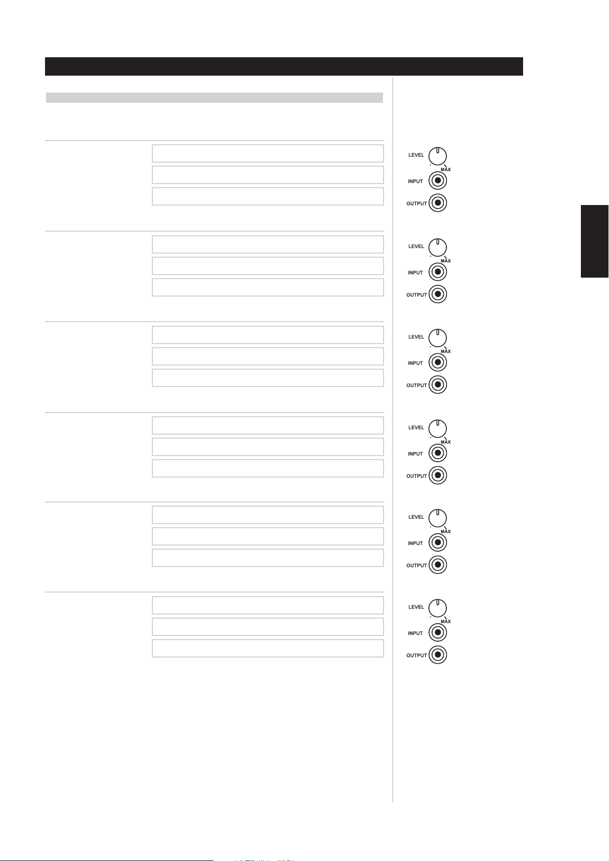
CONFIGURATION CLIENT (ENTRÉE / VOIE UTILISÉE) - SUITE
REPÉREZ LE RÉGLAGE INDIVIDUEL DE LA COMMANDE DE NIVEAU DE CHAQUE VOIE DE
L’ AMPLIFICATEUR SUR LES SCHÉMAS CI-DESSOUS
VOIE 1
SOURCE
PIÈCE
DESCRIPTION DU HAUT-PARLEUR
VOIE 2
SOURCE
Installation
ENGLISH
DESCRIPTION DU HAUT-PARLEUR
VOIE 3
DESCRIPTION DU HAUT-PARLEUR
VOIE 4
DESCRIPTION DU HAUT-PARLEUR
VOIE 5
DESCRIPTION DU HAUT-PARLEUR
PIÈCE
SOURCE
PIÈCE
SOURCE
PIÈCE
SOURCE
PIÈCE
FRANÇAISDEUTSCHNEDERLANDSESPAÑOL
ITALIANO
VOIE 6
DESCRIPTION DU HAUT-PARLEUR
SOURCE
PIÈCE
PORTUGUÊS
SVENSKA
15
Page 34

ENGLISH FRANÇAIS
DEUTSCH
Installation
CONFIGURATION CLIENT (ENTRÉE / VOIE UTILISÉE) - SUITE
REPÉREZ LE RÉGLAGE INDIVIDUEL DE LA COMMANDE DE NIVEAU DE CHAQUE VOIE DE
L’ AMPLIFICATEUR SUR LES SCHÉMAS CI-DESSOUS
VOIE 7
SOURCE
PIÈCE
DESCRIPTION DU HAUT-PARLEUR
VOIE 8
SOURCE
PIÈCE
DESCRIPTION DU HAUT-PARLEUR
VOIE 9
SOURCE
NEDERLANDS
ESPAÑOL
ITALIANO
PORTUGUÊS
PIÈCE
DESCRIPTION DU HAUT-PARLEUR
VOIE 10
SOURCE
PIÈCE
DESCRIPTION DU HAUT-PARLEUR
VOIE 11
SOURCE
PIÈCE
DESCRIPTION DU HAUT-PARLEUR
VOIE 12
SOURCE
PIÈCE
DESCRIPTION DU HAUT-PARLEUR
SVENSKA
16
Page 35

Dépannage
DÉPANNAGE PROBLÈME SOLUTION
Aucun son
Aucun son sur une voie
Graves faibles / mauvaise image stéréo
Son faible ou déformé dans une zone /
pièce, LED OMC allumée
• Câble secteur débranché.
• Sélecteur VACANCES [VACATION] en position
VACANCES.
• Mode Protection engagé.
• Fusible externe fondu.
• Haut-parleur incorrectement branché ou
détérioré.
• Câble d’entrée retiré ou mal relié à l’embase au
niveau du Flex-Pad.
• Court-circuit ou câble cassé dans un câble de
liaison ou de haut-parleur.
• Haut-parleurs câblés en déphasé. • Inversez le branchement du haut-parleur au
• Court-circuit dans un câble de haut-parleur vers
une zone / pièce.
• Niveau d’entrée trop élevé dans une ou plusieurs
voie(s) de l’amplificateur.
• Impédance trop faible sur une ou plusieurs
sorties de l’amplificateur correspondant à la zone
/ pièce concernée.
• Vérifiez que le câble secteur est bien branché et
que l’alimentation est présente.
• Mettez le sélecteur VACANCES [VACATION] en
position MARCHE [ON]
• Mettez l’amplificateur hors tension, en utilisant le
Sélecteur VACANCES [VACATION]. Vérifiez que
les ouïes de ventilation sur le dessus, les côtés et
l’arrière de l’amplificateur ne sont pas obstruées.
Après le refroidissement de l’amplificateur,
mettez l’amplificateur sous tension.
• Remplacez le fusible.
• Consultez le revendeur / installateur.
• Vérifiez tous les branchements sur les hautparleurs et sur l’amplificateur.
• Vérifiez les cordons et les câbles des Flex-Pad.
• Mettez l’amplificateur hors tension, en utilisant le
sélecteur VACANCES [VACATION], puis
remplacez les câbles défectueux.
niveau de la sortie incriminée de l’amplificateur.
• Vérifiez tous les branchements des haut-parleurs
dans la zone / pièce concernée.
• Mettez l’amplificateur hors tension, en utilisant le
sélecteur VACANCES [VACATION], puis
débranchez tour à tour les paires de câbles de
haut-parleurs de l’amplificateur, puis remettez le
sélecteur VACANCES [VACATION] en position
MARCHE [ON] et rétablissez la source audio.
Procédez ainsi jusqu’à ce que la LED OMC ne
s’allume plus. Remplacez le câble de haut-parleur
court-circuité de la zone / pièce concernée.
• Baissez le niveau d’entrée correspondant à la
pièce / zone incriminée.
•Trop de haut-parleurs connectés à une seule voie,
ou réglages d’impédance incorrects au niveau du
multiplexeur ou du transformateur d’impédance
des haut-parleurs. Débranchez certains hautparleurs et/ou consultez la documentation
fournie par le fabricant du multiplexeur de hautparleurs pour connaître le réglage correct des
impédances.
• Multiplexeur de haut-parleurs endommagé.
Remplacez le multiplexeur de haut-parleurs.
ENGLISH
FRANÇAISDEUTSCHNEDERLANDSESPAÑOL
ITALIANO
17
PORTUGUÊS
SVENSKA
Page 36

ENGLISH FRANÇAIS
DEUTSCH
NEDERLANDS
ESPAÑOL
ITALIANO
PORTUGUÊS
Caractéristiques
Puissance
85 Watts de puissance continue moyenne dans une impédance de 6 Ohms, pour toute
fréquence de 20 Hz à 20 kHz, toutes les voies étant pilotées avec une distorsion harmonique
totale inférieure à 0.03 %.
86 Watts de puissance continue moyenne dans une impédance de 4 Ohms, pour toute
fréquence de 20 Hz à 20 kHz, toutes les voies étant pilotées avec une distorsion harmonique
totale inférieure à 0.03 %.
Distorsion IM (SMPTE)
1 Watt à 80 Watts dans 6 Ohms < 0.03 %
1 Watt à 80 Watts dans 4 Ohms < 0.03 %
Distorsion IM (CCIF, Toute combinaison de 4 kHz à 20 kHz)
1 Watt à 80 Watts dans 6 Ohms < 0.03 %
1 Watt à 80 Watts dans 4 Ohms < 0.03 %
Distorsion harmonique totale + Bruit à 1 Watts dans 6 Ohms
20 Hz 0.03 %
1 kHz 0.03 %
10 kHz 0.03 %
20 kHz 0.03 %
Distorsion harmonique totale + Bruit à 80 Watts dans 6 Ohms
20 Hz 0.03 %
1 kHz 0.03 %
10 kHz 0.03 %
20 kHz 0.03 %
Réponse de fréquence à 1 Watt dans 6 Ohms
10 Hz à 20 kHz +0.5, -1.0 dB
Largeur de bande de Puissance (-3dB) 5 Hz à 45 kHz
Gain 28 dB
Plage de réglage des potentiomètres de l’amplificateur
Facteur d’amortissement > 30
Plage dynamique dans une charge de 6 Ohms 1.6 dB
Activation de l’OMC
Logique “ATO Logic”
Sensibilité de l’entrée capteur “SENSE” > 20mV eff.
Plage de tensions et impédance
de l’Entrée Asservissement 12V 10,0 V à 20,0 V CC, 100 kOhms
Courant et impédance
de la Sortie Asservissement 12V 25 +/- 5 mA, 470 Ohms
Impédance d’Entrée 25 kOhms
Sensibilité d’Entrée
80 Watts dans 6 Ohms 1 V eff.
1 Watt dans 6 Ohms 114 mV eff.
Facteur d’amortissement 20 Hz à 20 kHz < 31
Temps de montée
5 kHz, xxx V crête à crête, signal carré,
20 % à 80 % 4 µs
14 ± 2 dB
< 4 Ohms aux bornes de n’importe quelle sortie de HP
SVENSKA
18
Consommation (Continue, Toutes voies pilotées)
Repos 84/168 VA
Maximum 960/1920 VA
80 Watts dans 6 Ohms 744/1488 VA
80 Watts dans 4 Ohms 900/1800 VA
GÉNÉRALES
Alimentation (240 V disponible) 120 V CA / 50-60 Hz
Température ambiante de fonctionnement
Température de fonctionnement 20 °C au dessus de la température ambiante
Débit d’air de ventilation 4,25 m3/mn maximum
Dimensions châssis nu 437 x 133 x 451 mm
Dimensions maximales hors tout 480,1 x 481,7 x 144,8 mm
Poids CI 9060, emballé 25-27 kg, 34 kg
Poids CI 9120, emballé 35-37 kg, 44 kg
< 40 °C
ou 3 emplacements de châssis-rack
(avec pièces de montage dans châssis-rack,
pieds et bornes de haut-parleurs)
Page 37

Tableau de remplacement des fusibles
REMPLACEMENT DU FUSIBLE - VEUILLEZ LIRE ATTENTIVEMENT
Les fusibles indiqués dans le tableau ci-dessous ont été choisis avec discernement et ont été soumis à une
batterie de tests pour s’assurer qu’ils sont compatibles avec des performances optimales, tout en assurant
leurs fonctions de protection. Ne remplacez le FUSIBLE D’ALIMENTATION SECTEUR que par l’un des fusibles
spécifiés dans le tableau ci-dessous. N’UTILISEZ JAMAIS UN FUSIBLE DE TYPE DIFFÉRENT OU DONT
L’INTENSITÉ DE FUSION, LA COURBE TEMPS/INTENSITÉ OU LA VALEUR EST DIFFÉRENTE DE
CELLES INDIQUÉES. Tout non respect de cette précaution risque d’entraîner la détérioration des circuits
de l’amplificateur, DE CRÉER UN RISQUE D’INCENDIE ET/OU D’ANNULER LES SÉCURITÉS
INCORPORÉES DANS L’AMPLIFICATEUR. DE PLUS, CELA RISQUE D’ANNULER LA GARANTIE.
Modèle Bussman Littelfuse Bel
9120 AH MDA-20/250V 3AB 326020/250V s/o
9060 AH MDA-12/250V 3AB 326012/250V GSA 12/250
9120 C (1 & 2) MDA-10/250V 3AB 326010/250V GSA 10/250
9060 C (1 & 2) MDA-6/250V 3AB 326060/250V GSA 6/250
ENGLISH
FRANÇAISDEUTSCHNEDERLANDSESPAÑOL
19
ITALIANO
PORTUGUÊS
SVENSKA
Page 38

ENGLISH FRANÇAIS
DEUTSCH
NEDERLANDS
ESPAÑOL
ITALIANO
PORTUGUÊS
SVENSKA
2
Page 39

INHALTSVERZEICHNIS
I Vorbemerkung . . . . . . . . . . . . . . . . . . . . . . . . . . . . . . . . . . . . . . . . . . . . . . . . . . . . . . . . . . . . .3-5
Sicherheitshinweise. . . . . . . . . . . . . . . . . . . . . . . . . . . . . . . . . . . . . . . . . . . . . . . . . . . . . . . . . . . 4
II Betrieb . . . . . . . . . . . . . . . . . . . . . . . . . . . . . . . . . . . . . . . . . . . . . . . . . . . . . . . . . . . . . . . . . .6-10
NAD ATO Logic . . . . . . . . . . . . . . . . . . . . . . . . . . . . . . . . . . . . . . . . . . . . . . . . . . . . . . . . . . . . . 6
NAD OMC . . . . . . . . . . . . . . . . . . . . . . . . . . . . . . . . . . . . . . . . . . . . . . . . . . . . . . . . . . . . . . . . . 7
NAD Schutzschaltung . . . . . . . . . . . . . . . . . . . . . . . . . . . . . . . . . . . . . . . . . . . . . . . . . . . . . . . . . 7
III Installation . . . . . . . . . . . . . . . . . . . . . . . . . . . . . . . . . . . . . . . . . . . . . . . . . . . . . . . . . . . . .11-16
Rackmontage . . . . . . . . . . . . . . . . . . . . . . . . . . . . . . . . . . . . . . . . . . . . . . . . . . . . . . . . . . . . . . 11
Regalaufstellung. . . . . . . . . . . . . . . . . . . . . . . . . . . . . . . . . . . . . . . . . . . . . . . . . . . . . . . . . . . . 11
Lautsprecheranschluss. . . . . . . . . . . . . . . . . . . . . . . . . . . . . . . . . . . . . . . . . . . . . . . . . . . . . . . . 12
Systemkonfiguration (Eingang/Kanal-Zuweisung) . . . . . . . . . . . . . . . . . . . . . . . . . . . . . . . . . . . . 14
Systemkonfiguration (Flex-Pad) . . . . . . . . . . . . . . . . . . . . . . . . . . . . . . . . . . . . . . . . . . . . . . . . . 15
IV Problemlösung . . . . . . . . . . . . . . . . . . . . . . . . . . . . . . . . . . . . . . . . . . . . . . . . . . . . . . . . . . . .17
V Technische Daten . . . . . . . . . . . . . . . . . . . . . . . . . . . . . . . . . . . . . . . . . . . . . . . . . . . . . . . . . . .18
VI Ersatzsicherungstabelle . . . . . . . . . . . . . . . . . . . . . . . . . . . . . . . . . . . . . . . . . . . . . . . . . . . . .19
GERÄTEAUFSTELLER BITTE LESEN!
Die Befestigungsteile wurden speziell für die Verstärker der NAD CI-Serie entwickelt. Wir empfehlen daher,
keine anderen Befestigungsteile zu verwenden.
Die Verstärker der NAD CI-Serie haben aufgrund ihrer hohen Leistung schwere Netzteile. Für eine
Verstärker-Rackmontage ist deshalb möglicherweise mehr als eine Person erforderlich.
Vorbemerkung
ENGLISH
FRANÇAIS
DEUTSCHNEDERLANDSESPAÑOL
HINWEIS
Das Gewicht des Verstärkers muss bei der Aufstellung immer auf den Gerätefüßen ruhen. Stellen Sie
den Verstärker niemals auf seine Rückwand mit der Frontplatte nach oben. Die Ein/Ausgangsanschlüsse könnten dabei beschädigt werden.
Der Verstärker verursacht nur eine leichte Wärmeentwicklung, die aber eine interne Luftzirkulation
erforderlich macht. Achten Sie daher darauf, dass die Luftein- und -auslässe am Gerätegehäuse oben,
unten, seitlich und hinten nicht durch Papier oder andere Materialien verdeckt werden.
HINWEIS
Um der Gefahr von Feuer oder eines elektrischen Schlages vorzubeugen, achten Sie darauf, dass
Flüssigkeiten oder Feuchtigkeit nicht in den Verstärker eindringen können. Falls versehentlich Flüssigkeit
auf ihn geschüttet wird, das Gerät sofort ausschalten und den Netzstecker aus der Steckdose ziehen.
Öffnen Sie den Verstärker nicht und versuchen Sie nicht, ihn zu modifizieren oder selbst zu reparieren.
Lassen Sie alle Reparaturarbeiten nur von qualifiziertem Fachpersonal ausführen.
ITALIANO
PORTUGUÊS
Änderungen vorbehalten. Alle Angaben entsprechen den zur Zeit der Drucklegung gültigen technischen
Daten.
NAD®, OMC™, ATO Logic™ und Flex-Pad™ sind Warenzeichen von NAD Electronics International, einem
Unternehmensbereich von Lenbrook Industries Limited.
© 2000, NAD Electronics International, ein Unternehmensbereich von Lenbrook Industries Limited
SVENSKA
3
Page 40

ENGLISH FRANÇAIS
DEUTSCH
NEDERLANDS
ESPAÑOL
Vorbemerkung
ERLÄUTERUNG DER GRAFISCHEN SYMBOLE
Das Blitzsymbol mit Pfeil in einem gleichseitigen Dreieck soll den Benutzer vor einer nicht
isolierten, für das Risiko eines elektrischen Schlages für Personen ausreichend hohen
gefährlichen Spannung im Innern des Gerätegehäuses warnen.
Das Ausrufezeichen in einem gleichseitigen Dreieck soll den Benutzer darauf aufmerksam
machen, dass die mit dem Gerät gelieferte Dokumentation wichtige Betriebs- und
Wartungshinweise enthält.
ZUR BEACHTUNG
Vor der Benutzung des Gerätes die Bedienungsanleitung aufmerksam und ganz durchlesen. Die
Bedienungsanleitung zum späteren Nachschlagen unbedingt aufbewahren. Alle Warnhinweise in der
Bedienungsanleitung und am Gerät strengstens befolgen sowie die nachfolgenden Sicherheitsregeln
unbedingt einhalten.
AUFSTELLUNG
1Wasser und Feuchtigkeit - Das Gerät nicht in der Nähe von Wasser wie z. B. einer Badewanne, einem
Waschkessel, Schwimmbad o. ä. benutzen.
2 Hitze - Dieses Gerät nicht in der Nähe von Hitzequellen wie Heizlüftern, Öfen oder anderen
wärmeerzeugenden Geräten benutzen. Es darf auch nicht niedrigeren Temperaturen als 5 °C oder
höheren als 35 °C ausgesetzt werden.
3 Aufstellfläche - Das Gerät auf eine flache, ebene Fläche stellen.
4 Luftzirkulation - Damit eine ausreichende Wärmeabfuhr gewährleistet ist, muss das Gerät mit
ausreichend freiem Platz aufgestellt werden (mindestens 10 cm hinten und oben, und 5 cm auf jeder
Seite). - Nicht auf ein Bett, einen Teppich oder ähnliche Oberflächen stellen, die die Lüftungsöffnungen
blockieren können. - Das Gerät nicht in einen Bücherschrank oder in ein abgeschlossenes Rack stellen,
wo die Luftzirkulation verhindert wird.
5 Eindringen von Fremdkörpern und Flüssigkeit - Achten Sie darauf, dass keine Fremdkörper oder
Flüssigkeiten durch die Lüftungsöffnungen in das Innere des Gerätes gelangen.
6 Handwagen und Ständer - Steht das Gerät auf einem Ständer oder Handwagen, muss das Gerät
vorsichtig bewegt werden. Schnelles Anhalten, zu hohe Kraftanwendung und unebene Bodenflächen
können dazu führen, dass der Handwagen mit dem Gerät umkippt.
7Wand- oder Deckenmontage - Das Gerät darf nicht an einer Wand oder Decke montiert werden, es
sei denn, dies wird in der Bedienungsanleitung angegeben.
ITALIANO
PORTUGUÊS
SVENSKA
WARNUNG! UM DIE GEFAHR VON FEUER ODER STROMSCHLAG ZU VERHINDERN,
DIESES GERÄT NICHT REGEN ODER FEUCHTIGKEIT AUSSETZEN.
Dieses Gerät wurde in Übereinstimmung mit den Anforderungen gegen Hochfrequenzstörungen der EEC
RICHTLINIE 89/68/EEC und 73/23/EEC hergestellt.
4
Page 41

ELEKTRISCHE VERSORGUNG
1 Stromversorgungen - Dieses Gerät darf nur an solche Stromquellen angeschlossen werden, wie sie
in der Bedienungsanleitung beschrieben und am Gerät angegeben sind.
2 Polarität - Zur Sicherheit sind manche Geräte mit einem gepolten Wechselstromstecker ausgestattet,
der nur auf eine bestimmte Art in eine Steckdose paßt. Wenn ein Stecker schwer oder gar nicht in eine
Steckdose gesteckt werden kann, den Stecker umdrehen und noch einmal einstecken. Falls er sich
immer noch nicht leicht in eine Steckdose einstecken läßt, wenden Sie sich an einen Servicetechniker
oder ersetzen die Steckdose. Versuchen Sie auf keinen Fall, die Sicherheitsvorkehrung des gepolten
Steckers durch Gewaltanwendung zu umgehen.
3 Netzkabel - Ziehen Sie beim Ausstecken des Netzkabels nur am Netzstecker. Nicht am Kabel ziehen!
• Den Netzstecker niemals mit feuchten Händen anfassen. Stromschlag- und Brandgefahr!
• Zur Vermeidung von Knicken, Quetschen oder Darauftreten das Netzkabel sicher verlegen. Achten
Sie besonders auf das Kabel vom Gerät zur Steckdose.
• Steckdosen und Verlängerungskabel nicht überlasten. Stromschlag- und Brandgefahr!
4Verlängerungskabel - Zur Vermeidung von elektrischem Schlag durch freiliegende Steckerstifte, mit
Verlängerungskabeln, Gerätebuchsen oder anderen Netzausgängen keine gepolten Stecker
verwenden, wenn diese nicht vollständig eingesteckt werden können.
5Wenn das Gerät nicht verwendet wird - Wird das Gerät für mehrere Monate nicht verwendet, das
Netzkabel aus der Steckdose ausstecken. Bei eingestecktem Netzkabel fließt ständig ein geringer Strom
in das Gerät, auch wenn der Netzschalter ausgeschaltet ist.
Vorbemerkung
ENGLISH
FRANÇAIS
ACHTUNG
Durch Änderungen oder Einstellungen an diesem Gerät, die vom Hersteller nicht ausdrücklich genehmigt
sind, kann der Benutzer die Befugnis oder das Recht verlieren, das Gerät zu betreiben.
REPARATURSCHÄDEN
Lassen Sie das Gerät von einem qualifizierten Servicetechniker reparieren, wenn:
• Der Netzstecker beschädigt ist.
•Fremdkörper oder Flüssigkeit in das Gerät eingedrungen ist.
• Das Gerät Regen oder Wasser ausgesetzt war - Anscheinend nicht mehr normal funktioniert.
• Das Gerät eine deutliche Leistungsänderung erkennen läßt.
• Das Gerät hinuntergefallen ist, oder das Gehäuse beschädigt worden ist.
VERSUCHEN SIE NICHT, DAS GERÄT SELBST ZU REPARIEREN.
GERÄTEPASS
Schreiben Sie die Modellnummer und Seriennummer des Gerätes (auf der Geräte-Rückwand angegeben)
in den unten dafür vorgesehenen Bereich. Halten Sie diese Daten bereit, wenn Sie sich bei Problemen mit
dem Händler in Verbindung setzen.
Modell:
Seriennr.:
DEUTSCHNEDERLANDSESPAÑOL
ITALIANO
PORTUGUÊS
SVENSKA
5
Page 42

ENGLISH FRANÇAIS
Betrieb
NAD ATO LOGIC
Für eine uneingeschränkte Systemflexibilität kann der Verstärker der CI-Serie auf eine von drei Arten
eingeschaltet werden: Mit dem Schalter auf der Frontplatte, über den 12V-TRIGGER-Schaltkreis oder über
den „SLEEP/WAKE”-Signalerfassungsschaltkreis. Die EIN/AUS-Netzkontrolle wird über die automatische
Einschaltlogik (ATO Logic) durchgeführt, die erfordert, dass der Verstärker in derselben Weise in den
Bereitschaftsmodus geschaltet wird, in der er von diesem aus eingeschaltet worden ist. Mit anderen
Worten: Wenn der Verstärker über ein 12-V-Steuersignal eingeschaltet wird, kann er nicht mit dem
Schalter auf der Frontplatte in den Bereitschaftsmodus geschaltet werden, sondern er muss auf das
Wegfallen des 12-V-Steuersignals warten. In der Praxis werden Sie wahrscheinlich nur eine der Methoden
anwenden, sobald der Verstärker der NAD CI-Serie einmal aufgestellt ist.
ATO-LOGIC-TABELLE
DEUTSCH
NEDERLANDS
ESPAÑOL
ITALIANO
PORTUGUÊS
SCHALTER
Schalter VACATION steht auf
VACATION
Schalter VACATION steht auf ON
Front-Netzschalter gedrückt bei
Schalter VACATION auf ON
Front-Netzschalter gedrückt bei
Schalter VACATION auf ON
12V-TRIGGER
Schalter VACATION steht auf
VACATION
Schalter VACATION steht auf ON
12-V-INPUT-TRIGGER = 0V und
Schalter VACATION steht auf ON
12-V-INPUT-TRIGGER = 12V und
Schalter VACATION steht auf ON
SLEEP/WAKE
Schalter VACATION steht auf
VACATION
Schalter VACATION steht auf ON
Gelbe LED über
Front-Netzschalter
AUS AUS AUS AUS
EIN AUS AUS AUS
AUS EIN AUS AUS
EIN AUS AUS AUS
Gelbe LED über
Front-Netzschalter
AUS AUS AUS AUS
EIN AUS AUS AUS
EIN AUS AUS AUS
AUS AUS EIN AUS
Gelbe LED über
Front-Netzschalter
AUS AUS AUS AUS
EIN AUS AUS AUS
Grüne SCHALTER
LED
Grüne SCHALTER
LED
Grüne SCHALTER
LED
Grüne 12V-
TRIGGER LED Grüne SENSE LED
Grüne 12V-
TRIGGER LED Grüne SENSE LED
Grüne 12V-
TRIGGER LED Grüne SENSE LED
SVENSKA
Schalter SLEEP/WAKE SENSE DEFEAT
steht auf SENSE DEFEAT und
Schalter VACATION steht auf ON
Schalter SLEEP/WAKE SENSE DEFEAT
steht auf SLEEP/WAKE und Signal an
beliebigem Eingang ist größer als
20mV und Schalter VACATION steht
auf ON
EIN AUS AUS AUS
AUS AUS AUS EIN
6
Page 43

NAD OMC
Die NAD-eigene Ausgangspegelschaltung (Output Management Circuit, OMC) stellt sicher, daß bei jeder
geeigneten Lastimpedanz immer die volle Leistung zur Verfügung steht. Die OMC steuert einzelne
Verstärkerkanäle durch Kontrolle des Eingangspegels bei absichtlich übersteuertem Eingangssignal und/oder
im Falle eines Lautsprecher- oder Lautsprecherkabelschadens durch Kontrolle des Ausgangspegels. Dadurch
wird nicht nur der Verstärker geschützt, sondern auch die starke Erhitzung von angeschlossenen Lasten
verhindert – ein wichtiger Gesichtspunkt für die Zuverlässigkeit eines installierten Systems. Stellt die OMC
einen potentiellen Fehler fest und beginnt den Strom zu begrenzen, leuchtet zur Signalisierung des
Systemproblems für den Betreiber auf der Frontplatte eine gelbe LED auf. Bei aktiver OMC ist die
Wiedergabe des Verstärkers zwar weiterhin verzerrungsfrei, aber die Leistung im problematischen
Verstärkerkanal wird reduziert. Bleibt die Fehlerbedingung bestehen und die Impedanz wird zu niedrig,
aktivieren die betroffenen Kanäle die NAD Schutzschaltung (siehe NAD Schutzschaltung, unten).
NAD SCHUTZSCHALTUNG
Für jeden Entwicklungsschritt, sowohl elektronisch als auch mechanisch, wurde als primäres Ziel die
absolute Zuverlässigkeit des Verstärkers zugrundegelegt. Zum Verstärkerdesign der CI-Serie gehört daher
auch eine Schutzschaltung mit automatischem Reset. Diese schnellansprechende Schutzschaltung wird bei
Überhitzung des Verstärkers oder bei Kurzschlußbedingungen aktiviert und über eine rote LED auf der
Frontplatte signalisiert. Die Schutzschaltung wird nur für die Vestärker aktiviert, die von einem Kurzschluß
betroffen sind, alle anderen Kanäle arbeiten normal weiter. Treten wieder normale Betriebsbedingungen
ein, werden die betroffenen Kanäle zurückgesetzt. Für den unwahrscheinlichen Fall eines Verstärkerfehlers,
kann der CI-Serie-Verstärker leicht vor Ort repariert werden, da alle Verstärkerschaltkreise auf steckbaren
Modulen untergebracht sind.
Betrieb
ENGLISH
FRANÇAIS
DEUTSCHNEDERLANDSESPAÑOL
ITALIANO
PORTUGUÊS
SVENSKA
7
Page 44

ENGLISH FRANÇAIS
DEUTSCH
NEDERLANDS
ESPAÑOL
ITALIANO
PORTUGUÊS
SVENSKA
Betrieb
BEDIENELEMENTE UND ANSCHLÜSSE AUF DER RÜCKWAND
12 3 4 12 3 5 410 11
1 Pro Verstärkerkanal gibt es einen Kanaltrimmer CHANNEL. Mit
jedem Trimmer kann der jeweilige Eingang von einer minimalen bis
zur MAX-Stellung (ca. -13 dB bis 0 dB) eingestellt werden. Der
Einstellungsbereich ist so konzipiert, dass die LautsprecherEmpfindlichkeit für verschiedene Räume oder pro Lautsprecher in
Mehrfach-Lautsprecher-Installationen ausreichend eingestellt werden
kann. Dieser Trimmer dient ausschließlich dem Abgleich der
Empfindlichkeit, nicht der Lautstärkeeinstellung. Da es höchst
unwahrscheinlich ist, dass ein Trimmer nach der Systeminstallation
noch einmal eingestellt werden muss, haben wir die Trimmer auf der
Geräterückseite des Verstärkers untergebracht.
2 Da jeder CHANNEL INPUT OUTPUT des Verstärkers eine direkte
Durchgangs-verbindung ist, entspricht die Quellenimpedanz jedes
Kanals exakt der Ausgangsimpedanz. Die spezielle Ausführung der im
Lieferumfang des NAD Verstärkers der CI-Serie enthaltenen NADCinch-Kabel ermöglichen die Speisung von bis zu 6 Kanälen von
einem Kanal Flex-Pad STEREO und MONO OUT - ohne
Beeinträchtigung der Klangqualität. So kann man z. B. von Flex-Pad
OUT Rechts auf CHANNEL 1 INPUT, dann von CHANNEL 1
OUTPUT auf CHANNEL 2 INPUT, von CHANNEL 2 OUTPUT auf
CHANNEL 3 INPUT usw. bis zu 6 Eingangskanäle miteinander
verbinden. Die Brückenkabel der NAD CI-Serie sind speziell
entwickelte Hochleistungskabel mit niedriger Kapazität. Wir
empfehlen dringend, keine anderen Verbindungskabel als die
mit dem NAD Verstärker der CI-Serie mitgelieferten NAD CinchBrückenkabel zu verwenden, da es sonst zu bedeutenden
Verlusten in der Musikqualität oder anderen Problemen
kommen kann.
3 Flex-Pad MONO OUT führt das Summensignal aus rechtem und
linkem Stereo-eingang mit einer Ausgangsimpedanz von 75 Ohm.
Wir empfehlen dringend, mit diesem Ausgang MONO OUT
nicht mehr als 6 Verstärkereingänge anzusteuern.
4 Flex-Pad STEREO OUT rechts und links ist ein Stereopuffer mit einer
Ausgangsimpedanz von 75 Ohm pro Kanal, der pro Ausgang bis zu
6 NAD Verstärker der CI-Serie ansteuern kann. Wir empfehlen
dringend, nicht mehr als 6 Verstärkereingänge pro Flex-PadAusgang anzusteuern.
5 Flex-Pad STEREO IN rechts und links sind hochohmige Eingänge
speziell für den Anschluss von Vorverstärker- oder HeimkinoProzessor-Ausgängen. Wir empfehlen dringend, diese Eingänge
nicht mit Geräten ohne Lautstärkeeinsteller zu verbinden!
6 Der Schalter VACATION ist sozusagen der Hauptschalter des
Verstärkers. Steht dieser Schalter in Stellung ON und leuchtet die
gelbe LED über dem Netzschalter auf der Frontplatte, befindet sich
der Verstärker im Bereitschaftsmodus. Wird der Verstärker über einen
längeren Zeitraum nicht benutzt, stellen Sie den Schalter VACATION
in die Position VACATION.
7 Die Schaltlogik SLEEP/WAKE, SENSE/DEFEAT kontrolliert den
Standby/Ein-Status des Verstärkers über das (Nicht-)Vorhandensein
eines Audiosignals am Flex-Pad oder an den
Verstärkerkanaleingängen. Damit diese Kontrolle verwendet werden
kann, muss sich der Schalter SLEEP/WAKE, SENSE/DEFEAT in
Stellung SLEEP/WAKE befinden. In Stellung SENSE/DEFEAT ist diese
Kontrolle deaktiviert.
Steht der Schalter in Position SLEEP/WAKE, schaltet der NAD
Verstärker der CI-Serie sofort aus dem Bereitschaftsmodus ein, wenn
er an einem der Eingangskanäle ein Signal feststellt. Dies wird durch
die leuchtende LED SENSE auf der Verstärker-Frontplatte angezeigt
(Eingangssignal über 20mV/eff.). Sind ca. 5 Minuten lang keine
Audiosignale mehr vorhanden, schaltet der Verstärker automatisch
wieder in den Bereitschaftsmodus. Die grüne LED SENSE verlöscht
und die gelbe LED über dem Schalter auf der Frontplatte leuchtet auf.
Steht der Schalter in Position SENSE/DEFEAT, schaltet der Verstärker
auch beim Anliegen eines Signals an einem Kanal- oder Flex-Pad-
Eingang nicht ein.
8
Page 45

Betrieb
8 Für jeden 12V-TRIGGER-Ein-/Ausgang dient eine 3,5-mm-
Miniaturbuchse (mono), bei der der mittlere Kontakt das 12-VTriggersignal führt. Wir empfehlen für den Anschluss der 3,5-mmMonostecker ein hochwertiges, abgeschirmtes Kabel, um ein
versehentliches Triggern des Verstärkers durch magnetische
Interferenzen aus nahegelegenen elektronischen Geräten zu vermeiden.
Der Anschluss 12V-IN TRIGGER ermöglicht das Einschalten des NAD
Verstärkers der CI-Serie aus dem Bereitschaftsmodus über ein
externes 12-V-Signal. Damit der Verstärker nicht wieder ausschaltet,
muss es ein 12-V-Dauersignal sein. Sobald das 12-V-Signal nicht mehr
vorhanden ist, schaltet der Verstärker wieder in den
Bereitschaftsmodus.
Der Anschluss 12V-OUT TRIGGER ermöglicht die Steuerung von
anderen Geräten mit einer 12-V-Triggerung über den NAD Verstärker
der CI-Serie. Ist der NAD Verstärker der CI-Serie eingeschaltet, ist das
Signal am 12V-OUT TRIGGER dauerhaft vorhanden. Befindet sich
der Verstärker im Bereitschafts- oder VACATION-Modus, liegt kein
Signal an.
HINWEISE
• Überprüfen Sie die Daten des 12-V-Triggereingangs von anderen
Geräten und stellen Sie sicher, dass diese mit dem 12-VTriggerausgang des NAD Verstärkers der CI-Serie kompatibel sind.
• Alle 12-V-TRIGGER-Ein-/Ausgänge an anderen NAD-Geräten mit
einer 12-V-TRIGGER-Funktion sind mit der IN/OUT-12-V-TRIGGER-
Funktion von NAD Verstärkern der CI-Serie voll kompatibel.
• Bevor Sie Verbindungen zu irgendwelchen 12-V-TRIGGER-Ein- oder
-ausgängen herstellen, achten Sie darauf, dass alle Geräte vom Netz
getrennt sind.
• Falls Sie beim Anschließen, bei der Installation und/oder im Betrieb der
IN/OUT-12-V-TRIGGER-Verbindungen nicht sicher sind, fragen Sie
Ihren NAD-Händler oder Vertriebsbeauftragten.
• Nichtbeachten des Obengenannten kann zu Schäden am NAD
Verstärker der CI-Serie oder an mit ihm verbundenen Geräten führen.
11 In der Nähe des Netzkabels befindet sich ein Sicherungshalter. Für den
unwahrscheinlichen Fall, dass eine Sicherung ersetzt werden muss,
ziehen Sie das Netzkabel aus der Steckdose. Trennen Sie dann alle
Verbindungen vom Verstärker. Ersetzen Sie die Sicherung nur mit
einer Sicherung mit den gleichen Werten für Typ, Größe und
elektrischen Daten. Unter „Technische Daten der NAD Modelle CI
9060 und CI 9120” auf der Rückseite dieser Bedienungsanleitung
finden Sie die korrekten Daten für die Ersatzsicherung.
ACHTUNG
Wenn Sie als Ersatz keine Sicherung mit korrekten Daten wie
sie in „AUSWECHSELN DER SICHERUNG - BITTE GENAU
BEACHTEN” auf der Rückseite dieser Bedienungsanleitung im
Abschnitt „Ersatzsicherung” aufgeführt sind, verwenden, wird
entweder die Sicherung erneut durchbrennen oder der
Verstärker beschädigt.
ENGLISH
FRANÇAIS
DEUTSCHNEDERLANDSESPAÑOL
9 Pro Verstärkerkanal gibt es einen Satz Lautsprecheranschlussklemmen.
Zur Kennzeichnung ihrer Polarität sind diese mit „+” und „-” markiert.
10 Es gibt zwei diskrete Typen von Netzkabeln. Das Ihrem NAD Verstärker
der CI-Serie entsprechende Netzkabel finden Sie hier:
Stellen Sie vor dem Anschließen des Netzkabels an eine
spannungsführende Steckdose sicher, dass alle Ein-/Ausgänge zuerst
angeschlossen sind. Trennen Sie immer zuerst das Netzkabel von der
spannungsführenen Steckdose bevor Sie ein anderes Kabel vom CISerie-Verstärker entfernen. Wenn Sie ein Verlängerungskabel
verwenden müssen, wählen Sie eine schwere Ausführung entsprechend
dem Typ für große Elektrogeräte, wie z. B. ein Verlängerungskabel für
eine Klimaanlage (16 AWG). Wir empfehlen dringend, das VerstärkerNetzkabel nicht an den zusätzlichen Netzausgang eines Vorverstärkers
anzuschließen. Solche zusätzlichen Netzausgänge sind nicht dafür
vorgesehen, so hohe Versorgungsströme zu liefern, wie sie der NAD
Verstärker der CI-Serie benötigt.
ITALIANO
PORTUGUÊS
SVENSKA
9
Page 46

ENGLISH FRANÇAIS
Betrieb
BEDIENELEMENTE UND ANZEIGEN AUF DER FRONTPLATTE
DEUTSCH
NEDERLANDS
ESPAÑOL
ITALIANO
1 Damit die Verstärkerfunktion ATO Logic funktioniert, muss die
Bereitschaft-LED gelb leuchten. Das erreicht man durch Stellen des
Schalters „VACATION” in die Position ON (siehe „Bedienelemente
und Anschlüsse auf der Rückwand”: Abschnitt Schalter VACATION).
2 Der NAD Verstärker der CI-Serie wird mit der Taste auf der Frontplatte
ein- und in den Bereitschaftsmodus geschaltet. Zu dieser Taste gehört
die grüne LED mit der Bezeichnung SWITCH. Wenn Sie den
Verstärker mit der Taste auf der Frontplatte einschalten, verlöscht die
gelbe Bereitschafts-LED und die LED SWITCH leuchtet grün. Haben
Sie den Verstärker mit der Taste auf der Frontplatte eingeschaltet,
kann er auch nur über diese Taste wieder in den Bereitschaftsmodus
geschaltet werden.
3 Die LED 12V-TRIGGER leuchtet grün, wenn der Verstärker vom
Bereitschafts-modus über den 12-V-Eingang (siehe „Bedienelemente
und Anschlüsse auf der Rückwand”: Abschnitt 12V-TRIGGER
INPUT) eingeschaltet wird. Haben Sie den Verstärker über 12V-IN
TRIGGER eingeschaltet, kann er auch nur über den Wegfall dieser
12V wieder in den Bereitschaftsmodus geschaltet werden.
4 Die LED SENSE leuchtet grün, wenn der Verstärker an einem seiner
Eingänge ein Signal entdeckt, das größer als 20mV/eff ist (siehe
„Bedienelemente und Anschlüsse auf der Rückwand”: Abschnitt
SLEEP/WAKE, SENSE/DEFEAT). Haben Sie den Verstärker über den
Schaltkreis SLEEP/WAKE eingeschaltet, kann er erst wieder in den
Bereitschaftsmodus geschaltet werden, wenn an keinem
Verstärkereingang mehr ein Signal anliegt.
5 Die LED OMC leuchtet gelb, wenn der Verstärker ein zu hohes
Eingangssignal entdeckt, oder die Lastimpedanz unter 2 oder 3 Ohm
fällt. Beide Fälle stellen eine potentielle Fehlerbedingung dar. Wird der
Fehler beseitigt, verlöscht die LED OMC und der Vestärker kehrt in
den Normalbetrieb zurück.
6 Die LED PROTECTION leuchtet rot, wenn die Verstärker-
Schutzschaltung aktiv ist. In dem unwahrscheinlichen Fall von
Überhitzung z. B., würde die Schutzschaltung aktiv und die LED
Protection rot leuchten. Dieser Verstärkerstatuts bleibt so lange
erhalten, bis die Fehlerbedingung wieder beseitigt ist. Sobald der
Fehler behoben ist, wird die Schutzschaltung wieder deaktiviert und
der Verstärker kehrt in den normalen Betrieb zurück.
PORTUGUÊS
SVENSKA
10
Page 47

RACKMONTAGE
Eine Anleitung zur Rackmontage des NAD Verstärkers der CI-Serie wird zusammen mit den RackmontageTeilen geliefert. Neben dieser Anleitung finden Sie außerdem 8 Plastikbuchsen und 4 Schraubenbolzen 10-
32. Die Schraubenbolzen mit den speziell entwickelten Plastikbuchsen sollen Masseschleifen verhindern
und können das Gewicht des NAD Verstärkers der CI-Serie tragen (siehe Abbildung 1).
RACKEINBAUTRÄGER
(LINKS)
88,0 mm 3U Montageschienenloch
DIESE SCHULTERUNTERLEGSCHEIBEN SIND FÜR
DEN RACKEINBAU DIESES GERÄTES
BEI SACHGEMÄSSER VERWENDUNG (SIEHE
ABBILDUNG) ISOLIEREN DIE UNTERLEGSCHEIBEN
DEN VERSTÄRKER VOM RACK, VERHINDERN
ERDSCHLEIFEN UND BRUMMEN UND SCHÜTZEN
GEGEN BESCHÄDIGUNGEN DER
GERÄTEOBERFLÄCHE.
NR. 10-32UNF-3A SCHRAUBE
4 pro Gerät erforderlich
Installation
ENGLISH
FRANÇAIS
DEUTSCHNEDERLANDSESPAÑOL
RACK-MONTAGESCHIENE
EIA Standard RS-310-C
SCHULTERUNTERLEGSCHEIBEN
8 pro Gerät erforderlich
Abbildung 1
Da der NAD Verstärker der CI-Serie schwer ist, empfehlen wir für ein stabile Rackinstallation die
Verstärkermontage so nahe wie möglich am Rackboden.
Der NAD Verstärker der CI-Serie benötigt 3 Standardplätze in einem 19-Zoll-Rack nach EIA/IEC. Bei der
Rackmontage sollte besonders auf ausreichenden Platz für die Luftzirkulation rund um den Verstärker
geachtet werden. Wir empfehlen daher, mindestens einen Rackplatz über und unter dem Verstärker und
mehr als 5 - 7,5 cm an allen sechs Seiten des NAD Verstärkers der CI-Serie frei zu lassen. Lesen Sie bitte
auch die Hinweise zu den maximalen Luftzirkulationsanforderungen in „Luftzirkulation” auf der Rückseite
dieser Bedienungsanleitung.
REGALAUFSTELLUNG
ENTFERNEN DER RACKMONTAGE-HALTERUNGEN
Dieses Gerät kann auf jeder ebenen und zum Tragen des Verstärkergewichts ausreichend starken Fläche
aufgestellt werden. Das genaue Gewicht Ihres NAD Verstärkers der CI-Serie finden Sie auf der Rückseite
dieser Bedienungsanleitung im Abschnitt „Technische Daten”. Da der NAD Verstärker der CI-Serie mit
bereits montierten Rackbefestigungs-Teilen ausgeliefert wird, geben wir Ihnen nachfolgend eine Anleitung
zum Entfernen der Rackhalterungen. Wir empfehlen dringend, zur Vermeidung von Verletzungen oder
Beschädigungen des NAD Verstärkers diese Anleitung zu befolgen:
Stellen Sie den Verstärker zum Entfernen der Rackhalterung auf eine ebene Fläche und lösen Sie
die jeweils drei Befestigungsschrauben auf jeder Seite. Sind die Schrauben entfernt, schieben
Sie die Halterung aus der Führung im Gehäuseboden nach hinten hinaus und dann zu Ihnen hin.
ITALIANO
PORTUGUÊS
Bei Regalaufstellung des NAD Verstärkers der CI-Serie raten wir davon ab, weitere Geräte auf den
Verstärker zu stellen. Lassen Sie zur ausreichenden Luftzirkulation mindestens 5-7,5 cm an allen Seiten des
Verstärkers frei. Wir empfehlen dringend, die seitlichen, oberen, hinteren und vorderen Lüftungsschlitze
nicht zu blockieren. Da der Netztransformator ein starkes magnetisches Störfeld erzeugt, sollten
Plattenspieler (besonders mit einem magnetischen Tonabnehmersystem) oder Fernsehgeräte nicht neben,
direkt auf oder unter dem Verstärker aufgestellt werden.
SVENSKA
11
Page 48

ENGLISH FRANÇAIS
DEUTSCH
NEDERLANDS
ESPAÑOL
Installation
LAUTSPRECHERANSCHLUSS
Um auch höchste Stromspitzen bei niederohmigen Lautsprechern zu bewältigen, ist dieser Verstärker mit
speziellen Schraubanschlussklemmen mit hoher Strombelast-barkeit für den Lautsprecheranschluss
ausgestattet. Da an den Lautsprecherklemmen bei voller Verstärkerleistung Spannungen bis zu 100 V
anliegen können, sind die Klemmen mit Kunststoffabdeckungen geschützt. Schalten Sie den Verstärker vor
dem Anschließen von Lautsprecherkabeln durch Ziehen des Netzkabels aus der Steckdose aus.
Verbinden Sie die Lautsprecherleitungen mit den Klemmen „+” und „-” auf der Rückwand des NAD
Verstärkers der CI-Serie. Bei jedem Kanal ist die rote Klemme der positive „+” Ausgang und die schwarze
Klemme der negative „-” oder „Masse” Ausgang (siehe Abbildung 2).
Verwenden Sie Leitungen in schwerer Ausführung (2,5 mm_ oder höher), besonders mit 4-OhmLautsprecher. Blanke Leitungsenden können an den Schraubanschlussklemmen direkt angeschlossen
werden. Für eine länger haltende und besser gegen Korrosion geschützte Verbindung können Sie
Lautsprecherkabel mit vergoldeten Kabelenden (Endhülsen oder Kabelschuhe) verwenden, oder solche
Hilfsmittel selbst an den Leitungen anbringen. Die Verbindung mit den Schraubanschlussklemmen kann,
wie nachfolgend beschrieben, auf drei Arten ausgeführt werden.
1 Endhülsen: Eine Endhülse ist eine schlankes Metallröhrchen, das auf das blanke Ende eines Kabels
gequetscht oder gelötet wird. Der Gewindebolzen jeder Schraubanschlussklemme enthält eine
Bohrung, die Endhülsen mit einem Durchmesser von bis zu 3 mm aufnehmen kann. Lösen Sie die
Plastikmutter der Schraubanschlussklemme so weit, bis die Bohrung im Gewindebolzen freiliegt.
Führen Sie die Endhülse in die Bohrung ein und drehen die Plastikmutter im Uhrzeigersinn, bis sie fest
sitzt (siehe Abbildung 2).
2 Kabelschuhe: Lösen Sie die Plastikmutter, schieben den U-förmigen Kabelschuh in den Zwischenraum
unter der Plastikmutter und dem Gegenstück und drehen die Plastikmutter wieder fest (siehe
Abbildung 2).
3 Blanke Kabelenden: Trennen Sie die beiden Leiter des Kabels (bei Paarleitungen) und insolieren an jeder
Leitung ca. 1 cm ab. Verdrehen Sie in jedem Leiter die freiliegenden dünnen Litzen miteinander. Lösen
Sie die Plastikmuttern für „+” und „-”, führen die blanken Kabelenden in die jeweilige Bohrung im
Gewindebolzen ein und drehen die Plastikmutter wieder fest, bis sie das Kabel sicher hält (siehe
Abbildung 2). Stellen Sie dabei sicher, dass keine einzelnen Drahtlitzen das Chassis oder eine
benachbarte Anschlussklemme berühren. Um sicherzustellen, dass sich die Plastikmuttern nicht
gelockert haben, ziehen Sie sie nach ca. einer Woche noch einmal nach.
ITALIANO
PORTUGUÊS
SVENSKA
Spade Wire
Pin
Abbildung 2
12
Page 49

PHASENLAGE
Stereo-Lautsprecher müssen in Phase zueinander arbeiten, damit ein eindeutiges Stereoklangbild erzeugt
werden kann und die Ausgänge sich bei niedrigen Frequenzen gegenseitig verstärken und nicht aufheben.
Eine phasenrichtige Verbindung ist gewährleistet, wenn für jeden Kanal die rote Klemme (positiv) am
Verstärker mit der roten (positiven) Klemme am Lautsprecher verbunden wird. Wenn Sie Ihre Lautsprecher
leicht bewegen können, ist das Überprüfen der Phasenlage einfach. Schließen Sie beide Lautsprecher an,
stellen sie mit der Frontseite zueinander und nur ein paar Zentimeter auseinander auf, starten die
Musikwiedergabe und hören genau hin. Tauschen Sie dann den Anschluss der beiden Leitungen hinten an
EINEM Lautsprecher und hören wieder genau hin. Die Verbindung, bei der die Basswiedergabe voller und
breiter klingt, ist die richtige. Wenn Sie die richtige Phasenlage bestimmt haben, verbinden Sie die
Leitungen sicher mit den Lautsprecher-Anschlussklemmen. Achten Sie dabei darauf, dass keine losen
Drahtlitzen die falsche Klemme berühren und einen teilweisen Kurzschluss verursachen, und stellen Sie die
Lautsprecher wieder an ihren vorgesehenen Platz.
Ist es nicht möglich, die Lautsprecher einfach gegenüberzustellen, müssen Sie sich für die Phasenlage auf
die „Polarität” der Anschlussleitungen verlassen. Die Lautsprecher-Anschlussklemmen am Verstärker sind
für jeden Kanal rot „+” und schwarz „-” gekennzeichnet. Die Anschlussklemmen hinten an den
Lautsprechern sind ebenfalls nach Polarität entweder durch rote und schwarze Anschlussbuchsen oder
Etiketten „+”, „1”, oder „8 Ohm” für positiv und „-”, „0” oder „G” für negativ gekennzeichnet. Für
jeden Kanal muss die rote „+” Klemme am Verstärker mit der roten (positiven) Klemme am Lautsprecher
verbunden werden. Um dies zu erleichtern, haben die beiden Leiter eines Lautsprecherkabels verschiedene
Farben (kupfer/silber) oder sind auf der Isolierung eines Leiters mit einer kleinen Erhebung gekennzeichnet
oder geriffelt. Verwenden Sie diese Merkmale für die konsistente Verdrahtung von Lautsprechern eines
Stereo-Paares. Wenn Sie also den kupferfarbenen Draht (oder den mit der geriffelten Isolierung) an der
„+” Klemme des linken Verstärkerkanals anschließen, machen Sie das am rechten Kanal genauso. Wenn
Sie am anderen Ende der Leitung den kupferfarbenen Draht (oder den mit der geriffelten Isolierung) an
der roten (positiven) Klemme des Lautsprechers für den linken Kanal anschließen, machen Sie das für den
rechten Lautsprecher genauso.
Installation
ENGLISH
FRANÇAIS
DEUTSCHNEDERLANDSESPAÑOL
HINWEIS
Sicherheitsorganisationen empfehlen, die Lautsprecheranschlussklemmen von sehr großen
Leistungsverstärkern abzudecken. An diesen Klemmen können bei voller Verstärkerleistung gefährliche
Spannungen anliegen. Zu Ihrem Schutz und in Übereinstimmung mit diesen Richtlinien haben wir für
den NAD Verstärker der CI-Serie Lautsprecheranschlussklemmen der höchsten Qualität ausgewählt.
Diese Klemmen werden durch Plastikmuttern abgedeckt, die das Berühren von Metallteilen sicher
verhindern.
ITALIANO
PORTUGUÊS
13
SVENSKA
Page 50

ENGLISH FRANÇAIS
DEUTSCH
NEDERLANDS
Installation
GERÄTEAUFSTELLER BITTE LESEN!
Die folgenden Tabellen sollten vollständig ausgefüllt und dem Besitzer des NAD Verstärkers der CI-Serie
zum späteren Nachschlagen ausgehändigt werden. Notieren Sie alle Lautsprecher-Standorte, Zonen,
Steuerungen, Quellen und einzelne Verstärkerpegeleinstellungen.
NAD MODELL-NUMMER
ANZAHL der ZONEN pro
VERSTÄRKER
STANDORT des NAD VERSTÄRKERS
DER CI-SERIE
VERSTÄRKER-NETZSTEUERUNG
QUELLE & BESCHREIBUNG DER NETZSTEUERUNG
QUELLE FÜR 12V-TRIGGER
VOM NAD CI 12V-TRIGGER
ANGESTEUERTE GERÄTE
QUELLE FÜR SIGNALERKENNUNG
SYSTEMKONFIGURATION (FLEX-PAD)
FLEX-PAD FÜR DIE ERSTEN 6 KANÄLE
QUELLE L
ESPAÑOL
ITALIANO
PORTUGUÊS
SVENSKA
QUELLE R
ZIEL L
ZIEL R
ZIEL MONO
FLEX-PAD FÜR DIE ZWEITEN 6 KANÄLE
ZIEL L
ZIEL R
ZIEL MONO
14
Page 51

SYSTEMKONFIGURATION (EINGANG/KANAL-ZUWEISUNG)
EINZELNE VERSTÄRKERPEGELEINSTELLUNGEN FÜR JEDEN KANAL MARKIEREN
CHANNEL 1
QUELL
STANDOR
LAUTSPRECHER
CHANNEL 2
QUELLE
Installation
ENGLISH
CHANNEL 3
CHANNEL 4
CHANNEL 5
STANDORT
LAUTSPRECHER
QUELLE
STANDORT
LAUTSPRECHER
QUELLE
STANDORT
LAUTSPRECHER
QUELLE
STANDORT
LAUTSPRECHER
FRANÇAIS
DEUTSCHNEDERLANDSESPAÑOL
ITALIANO
CHANNEL 6
QUELLE
STANDORT
LAUTSPRECHER
PORTUGUÊS
SVENSKA
15
Page 52

Installation
SYSTEMKONFIGURATION (EINGANG/KANAL-ZUWEISUNG FORTGES.)
EINZELNE VERSTÄRKERPEGELEINSTELLUNGEN FÜR JEDEN KANAL MARKIEREN
ENGLISH FRANÇAIS
DEUTSCH
NEDERLANDS
CHANNEL 7
QUELLE
STANDORT
LAUTSPRECHER
CHANNEL 8
QUELLE
STANDORT
LAUTSPRECHER
CHANNEL 9
QUELLE
STANDOR
LAUTSPRECHER
CHANNEL 10
QUELLE
ESPAÑOL
ITALIANO
PORTUGUÊS
SVENSKA
STANDORT
LAUTSPRECHER
CHANNEL 11
QUELLE
STANDORT
LAUTSPRECHER
CHANNEL 12
QUELLE
STANDORT
LAUTSPRECHER
16
Page 53

Problemlösung
PROBLEM URSACHE ABHILFE
Kein Ton
Ein Kanal ohne Ton
Schwache Bässe/schlechtes
Stereoklangbild
Schwacher oder verzerrter Ton aus einer
Zone/Raum und LED OMC leuchtet
• Netzkabel ausgesteckt.
• Schalter VACATION steht auf VACATION.
• Schutzschaltung hat ausgelöst.
• Externe Sicherung durchgebrannt.
• Lautsprecher nicht richtig angeschlossen oder
defekt.
• Eingangskabel lose oder schlechter Kontakt mit
Flex-Pad-Buchse.
• Kurzschluss oder Kabelbruch in einem defekten
Verbindungs- oder Lautsprecherkabel.
• Lautsprecherverdrahtung verpolt • Anschluss am verdächtigen Verstärkerausgang
• Kurzschluss in Lautsprecherkabel zu Zone/Raum.
• Netzkabel und Netzschalter überprüfen
• Schalter VACATION in Position ON stellen.
•Verstärker mit Schalter VACATION auschalten.
Sicherstellen, dass Lüftungsschlitze oben, seitlich
und hinten nicht blockiert sind. Nach Abkühlung
des Verstärkers wieder einschalten.
• Sicherung ersetzen.
• Händler/Geräteaufsteller fragen.
• Alle Verbindungen an den Lautsprechern und am
Verstärker überprüfen.
• Kabel und Flex-Pad-Kabel überprüfen.
•Verstärker in den VACATION-Modus schalten,
Kabel prüfen und bei Bedarf ersetzen.
umdrehen.
• Alle Lautsprecheranschlüsse in der betroffenen
Zone/Raum überprüfen.
•Verstärker mit dem Schalter VACATION
ausschalten und nacheinander jeweils ein Paar
Lautsprecher vom Verstärker trennen und danach
den Schalter VACATION wieder in die Position
ON Stellen und die Audioquelle wieder
aktivieren. Diesen Test so lange fortsetzen bis die
LED OMC verlöscht. Defektes Lautsprecherkabel
zur Zone/Raum ersetzen.
ENGLISH
FRANÇAIS
DEUTSCHNEDERLANDSESPAÑOL
• Zu hoher Eingangspegel an einem oder
mehreren Verstärkerkanälen.
• Zu niedrige Impedanz in einer oder mehreren
Verstärkerzonen/räumen
• Eingangspegel von verdächtiger Zone/Raum
verringern.
• An einem Kanal zu viele Lautsprecher
angeschlossen oder falsche Lautsprecherverteileroder Übertragerimpedanz. Einige Lautsprecher
entfernen oder Lautsprecherverteiler überprüfen,
und/oder mitgelieferte Dokumentation des
Verteilerherstellers auf korrekte Impedanzwerte
überprüfen.
• Lautsprecherverteiler defekt. Verteiler ersetzen.
ITALIANO
PORTUGUÊS
SVENSKA
17
Page 54

ENGLISH FRANÇAIS
DEUTSCH
NEDERLANDS
ESPAÑOL
ITALIANO
Technische Daten
TECHNISCHE DATEN
Leistung
85 Watt Dauer-Durchschnittsleistung an 6 Ohm bei allen Frequenzen zwischen 20Hz und 20kHz,
an allen Kanälen bei weniger als 0.03% Gesamtklirrfaktor.
86 Watt Dauer-Durchschnittsleistung an 4 Ohm bei allen Frequenzen zwischen 20Hz und 20kHz,
an allen Kanälen bei weniger als 0.03% Gesamtklirrfaktor.
IM-Verzerrung (SMPTE)
1 Watt bis 80 Watts an 6 Ohm < 0.03 %
1 Watt bis 80 Watts an 4 Ohm < 0.03 %
IM-Verzerrung (CCIF, jede Kombination von 4kHz bis 20kHz)
1 Watt bis 80 Watts an 6 Ohm < 0.03 %
1 Watt bis 80 Watts an 4 Ohm < 0.03 %
Gesamtklirrfaktor + Rauschen bei 1 Watt an 6 Ohm
20Hz 0.03 %
1kHz 0.03 %
10kHz 0.03 %
20kHz 0.03 %
Gesamtklirrfaktor + Rauschen bei 80 Watt an 4 Ohm
20Hz 0.03 %
1kHz 0.03 %
10kHz 0.03 %
20kHz 0.03 %
Frequenzgang bei 1 Watt an 6 Ohm
10Hz bis 20kHz + 0.5, -1.0dB
Leistungsbandbreite (-3dB) 5Hz to 45kHz
Verstärkung 28dB
Einstellbereich der Verstärker-Trimmer 14 ±2 dB
Dämpfungsfaktor >30
Dynamikumfang an 6 Ohm 1.6dB
OMC Aktivierung < 4 Ohm an jeder Lautsprecheranschlussklemme
ATO Logic
SENSE-Eingangsempfindlichkeit >20mV rms
12V Trigger Eingang, Spannungsbereich, Impedanz 10 bis 20 V=, 100 kOhm
12V Trigger Ausgang, Strom, Impedanz 25 +/- 5mA, 470 Ohm
Eingangsimpedanz 25 kOhm
Eingangsempfindlichkeit
80 Watts an 6 Ohm 1V/eff.
1 Watt an 6 Ohm 114mV/eff.
Dämpfungsfaktor 20 Hz bis 20 kHz <31
Anstiegszeit
5 kHz, 50V Spitze/Spitze Rechteckspannung
20% bis 80% 4 us
PORTUGUÊS
SVENSKA
Leistungsaufnahme (Dauerbetrieb, alle Kanäle angesteuert)
Ruhe 84/168 VA
Maximal 960/1920 VA
80 Watts an 6 Ohm 744/1488 VA
80 Watts an 4 Ohm 900/1800 VA
ALLGEMEIN
Netz (lieferbar für 240V) 120 V~/50-60 Hz
Umgebungstemperatur < 40° Celsius
Betriebstemperatur 20° Celsius über Umgebungstemperatur
Luftzirkulation 4,25 cbm/Minute maximal
Chassis-Nettoabmessungen 437 x 133 x 451 mm oder 3 HE
Maximale Bruttoabmessungen 480,1 x 481,7 x 144.8 mm
(inkl. Rackbefestigungsteile, Füße
und Lautsprecherklemmen)
Gewicht CI 9060, verpackt 25-27 kg, 34 kg
Gewicht CI 9120, verpackt 35-37 kg, 44 kg
18
Page 55

Ersatzsicherungstabelle
AUSWECHSELN DER SICHERUNG - BITTE GENAU BEACHTEN
Die in der untenstehenden Tabelle aufgeführten Sicherungen wurden auf optimale Leistung unter
Beibehaltung der Schutzfunktionen sorgfältig ausgewählt und gründlich getestet. Ersetzen Sie die
Netzsicherung daher nur mit einer Sicherung des in der Tabelle angegebenen Typs. VERWENDEN SIE
KEINE ERSATZSICHERUNG EINES ANDEREN TYPS ODER MIT ANDEREN NENNWERTEN FÜR
STROM, ZEIT/STROM-KURVEN ODER SONSTIGEN DATEN. Das Nichtbeachten dieser
Sicherheitsmaßnahme kann Schäden an den Verstärker-Schaltkreisen verursachen, KANN ZU
BRANDGEFAHR FÜHREN UND/ODER DIE EINGEBAUTEN SICHERHEITSEINRICHTUNGEN ZUNICHTE
MACHEN UND DEN VERLUST DES GEWÄHRLEISTUNGSANSPRUCHS NACH SICH ZIEHEN.
Modell Bussman Littlefuse Bel
9120 AH MDA-20/250V 3AB 326020/250V N/A
9060 AH MDA-12/250V 3AB 326012/250V GSA 12/250
9120 C (1 & 2) MDA-10/250V 3AB 326010/250V GSA 10/250
9060 C (1 & 2) MDA-6/250V 3AB 326060/250V GSA 6/250
ENGLISH
FRANÇAIS
DEUTSCHNEDERLANDSESPAÑOL
19
ITALIANO
PORTUGUÊS
SVENSKA
Page 56

ENGLISH FRANÇAIS
DEUTSCH
ESPAÑOL
ITALIANO
PORTUGUÊS
SVENSKA
2
Page 57

INDICE DE MATERIAS
I Introducción . . . . . . . . . . . . . . . . . . . . . . . . . . . . . . . . . . . . . . . . . . . . . . . . . . . . . . . . . . . . . . .3-5
Instrucciones de seguridad . . . . . . . . . . . . . . . . . . . . . . . . . . . . . . . . . . . . . . . . . . . . . . . . . . . . . 4
II Funcionamiento . . . . . . . . . . . . . . . . . . . . . . . . . . . . . . . . . . . . . . . . . . . . . . . . . . . . . . . . . .6-10
NAD ATO Logic . . . . . . . . . . . . . . . . . . . . . . . . . . . . . . . . . . . . . . . . . . . . . . . . . . . . . . . . . . . . . 6
NAD OMC . . . . . . . . . . . . . . . . . . . . . . . . . . . . . . . . . . . . . . . . . . . . . . . . . . . . . . . . . . . . . . . . . 7
Circuitería de protección NAD. . . . . . . . . . . . . . . . . . . . . . . . . . . . . . . . . . . . . . . . . . . . . . . . . . . 7
III Instalación . . . . . . . . . . . . . . . . . . . . . . . . . . . . . . . . . . . . . . . . . . . . . . . . . . . . . . . . . . . . .11-16
Montaje en bastidor . . . . . . . . . . . . . . . . . . . . . . . . . . . . . . . . . . . . . . . . . . . . . . . . . . . . . . . . . 11
Montaje en estante . . . . . . . . . . . . . . . . . . . . . . . . . . . . . . . . . . . . . . . . . . . . . . . . . . . . . . . . . 11
Interconexión de altavoces . . . . . . . . . . . . . . . . . . . . . . . . . . . . . . . . . . . . . . . . . . . . . . . . . . . . 12
Configuración del cliente (destino de entradas/canales) . . . . . . . . . . . . . . . . . . . . . . . . . . . . . . . 14
Configuración del cliente (Flex-Pad) . . . . . . . . . . . . . . . . . . . . . . . . . . . . . . . . . . . . . . . . . . . . . . 15
IV Investigación de Averías . . . . . . . . . . . . . . . . . . . . . . . . . . . . . . . . . . . . . . . . . . . . . . . . . . . .17
V Características técnicas . . . . . . . . . . . . . . . . . . . . . . . . . . . . . . . . . . . . . . . . . . . . . . . . . . . . . .18
VI Tabla para el recambio de fusibles . . . . . . . . . . . . . . . . . . . . . . . . . . . . . . . . . . . . . . . . . . . . .19
ATENCIÓN AL PERSONAL DE INSTALACIÓN
Los componentes de montaje han sido diseñados específicamente para los amplificadores NAD de la serie
CI. Recomendamos que no se sustituyan dichos componentes estructurales por otros.
Como resultado de la elevada capacidad de potencia de los amplificadores NAD de la serie I, la fuente de
alimentación es pesada y es posible que se requiera más de una persona para su instalación, cuando se
monte el amplificador en el bastidor.
Introducción
ENGLISH
FRANÇAISDEUTSCH
NOTA
Es indispensable que el peso del amplificador descanse siempre sobre los pies inferiores cuando se
coloque en una superficie. No deberá nunca colocarse el amplificador hacia abajo sobre su panel
trasero, con el panel delantero de cara hacia arriba ya que, de lo contrario, se arriesga ocasionar daños
a los conectores de entrada y salida.
El amplificador genera una moderada cantidad de calor, lo que es susceptible de ventilación interna. No
deberá permitirse que se obstruyan las rejillas de admisión y salida del aire de las partes superior, inferior,
laterales y tapa posterior con papeles u otros materiales.
NOTA
Para evitar el riesgo de incendio o electrocución, no se permitirá que penetre en el amplificador ningún
líquido o humedad. Si se vertiera accidentalmente líquido sobre el mismo, deberá desconectarse
inmediatamente de la alimentación y retirar la clavija del cable de la red de c.a. del enchufe.
No deberá abrirse el amplificador ni intentar modificar o repararlo por cuenta propia. Refiérase toda
reparación a un radiotécnico.
ESPAÑOL
ITALIANO
PORTUGUÊS
Las características técnicas están sujetas a cualquier alteración sin previo aviso. Todas las características son
vigentes al tiempo de imprimirse.
NAD®, OMC™, ATO Logic™ y Flex-Pad™ son marcas registradas de NAD Electronics International, una
división de Lenbrook Industries Limited.
©2000, NAD Electronics International, una división de Lenbrook Industries Limited.
SVENSKA
3
Page 58

ENGLISH FRANÇAIS
DEUTSCH
ESPAÑOL
Introducción
EXPIACIÓN DE SIMBOLOS GRAFICOS
El relámpago con símbolo de cabeza de flecha dentro de un triángulo equilátero es para alertar
al usuario sobre la presencia de "montaje peligroso" no aislado dentro de la caja del producto
que puede tener magnitud suficiente para constituir un riesgo de choque eléctrico para las
personas.
El signo de exclamación dentro de un triángulo equilátero es para alertar al usuario sobre la
presencia de instrucciones importantes de funcionamiento y mantenimiento (servicio) en los
impresos que acompañan al aparato.
PRECAUCIONES
Lea las Instrucciones de Funcionamiento cuidadosa y completamente antes de hacer funcionar el equipo.
Asegúrese de guardar las Instrucciones de Funcionamiento para consulta futura. Todas las advertencias y
precauciones de las Instrucciones de Funcionamiento y las que hay en el equipo se deben cumplir
estrictamente, así como también las sugerencias de seguridad siguientes.
INSTALACION
1 Agua y Humedad - No use este equipo cerca del agua como cerca de una bañera, lavabo, piscina, o
similar.
2 Calor - No use este equipo cerca de fuentes de calor, incluyendo ventilaciones de calefacción, estufas
y otros aparatos que generan calor. Tampoco debe colocarse en temperaturas inferiores a 5ºC (41°F) o
superiores a 35°C (95°F).
3 Superficie de montaje - Coloque el equipo sobre una superficie plana y uniforme.
4Ventilación - El equipo debe colocarse con un espacio adecuado a su alrededor, de modo que se
asegure ventilación apropiada. Deje una separación de 10 cm (4 in.) desde la parte trasera y la parte
superior del equipo, y 5 cm (2 in.) desde cada lado. - No lo ponga sobre una cama, estera, o superficie
similar que pueda bloquear las aberturas de ventilación. - No instale el equipo en un armario de
biblioteca, ni en un estante herméticamente cerrado en que se impida la ventilación.
5 Entrada de objetos y líquidos - Tenga cuidado de que no penetren en el equipo objetos ni líquidos
a través de las aberturas de ventilación.
6 Carritos y soportes - Si se coloca o monta sobre un soporte o carrito, el equipo ha de moverse con
cuidado. Las paradas rápidas, la fuerza excesiva, y las superficies desiguales pueden hacer que el equipo
y el carrito se vuelquen o caigan.
7 Montaje en pared o techo - El equipo no debe montarse sobre una pared o techo, a no ser que se
especifique en las Instrucciones de Funcionamiento.
ITALIANO
PORTUGUÊS
SVENSKA
¡ADVERTENCIA! PARA REDUCIR EL RIESGO DE INCENDIO O CHOQUE ELECTRICO, NO
EXPONGA ESTE APARATO A LA LLUVIA O LA HUMEDAD
Este producto está fabricado para que cumpla con los requisitos de la interferencia de radio de la
COMUNIDAD EUROPEA, DIRECTIVA EEC 89/68/EEC y 73/23/EEC.
4
Page 59

ENERGIA ELECTRICA
1 Fuentes de Energía Eléctrica - Conecte este equipo solamente a las fuentes de energía eléctrica
especificadas en las Instrucciones de Funcionamiento, y tal como se indica con marcas en el equipo.
2 Polarización - Como prestación de seguridad algunos equipos tienen enchufes polarizados de CA que
únicamente pueden insertarse de una manera en una toma de energía eléctrica. Si es difícil o imposible
insertar el enchufe de CA en una toma, dé la vuelta al enchufe e inténtelo otra vez. Si todavía no se
inserta fácilmente en la toma, rogamos llame a un técnico de servicio para que haga el servicio o
cambie la toma. Para evitar que se inutilice la prestación de seguridad del enchufe polarizado, no lo
fuerce para insertarlo en la toma.
3 Cordón eléctrico de CA - Cuando desconecte el cordón eléctrico de CA, sáquelo tirando del enchufe
eléctrico de CA. No tire del cordón mismo.
• No maneje jamás el enchufe eléctrico de CA con las manos húmedas, porque esto podría producir
un incendio o choque eléctrico.
• Los cordones eléctricos deben enrutarse de modo que se eviten curvas severas, se perforen los
cordones o se pisen. Preste atención particular al cordón que sale del equipo y va a la toma
eléctrica.
• Evite sobrecargar las tomas de CA y los cordones de tensión más allá de su capacidad, porque esto
podría producir incendio o choque eléctrico.
4 Cordón de extensión - Para ayudar a impedir el choque eléctrico, no use un enchufe eléctrico de CA
polarizado con un cordón de extensión, un receptáculo u otras tomas a no ser que el enchufe
polarizado pueda insertarse completamente para impedir que queden expuestas las espinas del
enchufe.
5 Cuando no se usa - Desenchufe el cordón eléctrico de CA de la toma de CA si el equipo no va a
usarse durante varios meses o más. Cuando el enchufe está insertado, continúa pasando al equipo una
pequeña cantidad de corriente, aún cuando la alimentación eléctrica esté desconectada.
Introducción
ENGLISH
FRANÇAISDEUTSCH
PRECAUCION
Las modificaciones o ajustes de este producto, no expresamente aprobadas por el fabricante, pueden
anular el derecho o autorización del usuario a hacer funcionar este producto.
DAÑO QUE REQUIERE SERVICIO
Haga que el servicio del equipo lo realice un técnico de servicio si
• El enchufe eléctrico de CA se ha dañado.
• Han penetrado en el equipo objetos o líquidos extraños.
• El equipo ha quedado expuesto a la lluvia o al agua - el equipo no parece funcionar normalmente.
• El equipo muestra un notable cambio de rendimiento.
• El equipo se ha caído, o el armarito ha sido dañado.
NO INTENTE HACER USTED MISMO EL SERVICIO DEL EQUIPO
REGISTRO DEL PROPIETARIO
Para su comodidad, registre el número de modelo y número de serie (los encontrará en la parte trasera de
su aparato) en el espacio provisto a continuación. Rogamos los indique cuando contacte a su concesionario
en caso de dificultad.
Modelo No. :
Serie No. :.
ESPAÑOL
ITALIANO
PORTUGUÊS
SVENSKA
5
Page 60

ENGLISH FRANÇAIS
Funcionamiento
NAD ATO LOGIC: (LOGITRÓNICA ATO DE NAD)
Para la obtención de una flexibilidad total del sistema logitrónico, los amplificadores de la serie CI pueden
conmutarse en cualquiera de las tres modalidades discretas, a saber: desde el interruptor del panel
delantero, por medio del circuito conmutador de 12 V (12V-TRIGGER), o bien merced al circuito sensor de
la señal “SLEEP/WAKE”. El mando de conmutación/desconmutación (ON/OFF) de la red corre a cargo del
circuito lógico de conmutación automatica o ATO Logic, que exige el retorno del amplificador al estado de
“espera”, de la misma manera por la que fue activado. En otras palabras, si se conmuta el amplificador
por medio de una señal de mando de 12 V, no podrá conmutarse a la modalidad de espera por el
interruptor del panel delantero; deberá esperar hasta que se retire la señal de mando de 12 voltios. En la
práctica, es probable que se utilice un solo procedimiento, una vez se haya instalado un amplificador NAD
de la serie CI.
TABLA DE ATO LOGIC (LOGITRÓNICA ATO)
DEUTSCH
ESPAÑOL
ITALIANO
PORTUGUÊS
SWITCH
Conmutador VACATION en
VACATION
Conmutador VACATION en ON
Oprímase int delantero red con
conmutador VACATION en ON
Oprímase int delantero red con
conmutador VACATION en ON
12V TRIGGER
Conmutador VACATION en
VACATION
Conmutador VACATION en ON
ENTRADA 12V TRIGGER = 0V con
conmutador VACATION en ON
ENTRADA 12V TRIGGER = 0V con
conmutador VACATION en ON
SENSE
Conmutador VACATION en
VACATION
Conmutador VACATION en ON
LED anaranjado
encima int. red LED verde SWITCH
OFF OFF OFF OFF
ON OFF OFF OFF
OFF ON OFF OFF
ON OFF OFF OFF
LED anaranjado
encima int. red LED verde SWITCH
OFF OFF OFF OFF
ON OFF OFF OFF
ON OFF OFF OFF
OFF OFF ON OFF
LED anaranjado
encima int. red LED verde SWITCH
OFF OFF OFF OFF
ON OFF OFF OFF
LED verde 12V
TRIGGER LED verde SENSE
LED verde 12V
TRIGGER LED verde SENSE
LED verde 12V
TRIGGER LED verde SENSE
SVENSKA
Conmutador SLEEP/WAKE
SENSE/DEFEAT en posición
SENSE/DEFEAT con conmutador
VACATION en ON
Conmutador SLEEP/WAKE
SENSE/DEFEAT en posición
SLEEP/WAKE y cualquier fuente de
entrada mayor de 20mV con
conmutador VACATION en ON
ON OFF OFF OFF
OFF OFF OFF ON
6
Page 61

NAD OMC (CIRCUITO DE CONTROL DE LA POTENCIA)
El Circuito de Gestión de Salidas (OMC) propio de NAD asegura que la potencia completa se halle disponible
a cualquier impedancia de carga razonable. El OMC controla canales de amplificadores individuales
gestionando el nivel de entradas, en casos de señal de entrada y/o nivel de salida deliberadamente excesivos,
así como en el caso de fallo de altavoces o de cables de altavoces. Esto no sólo protege el amplificador, sino
también impide que se calienten excesivamente cargas acopladas al amplificador, factor éste de importancia
cuando ha de considerarse la fiabilidad de un sistema instalado. Una vez que el OMC detecta una situación
de fallo posible y comienza a limitar el flujo de corriente, se enciende en el panel delantero un diodo LED
de color ámbar para advertir al instalador/propietario acerca de la existencia de un problema en el sistema.
Cuando se activa el OMC, el amplificador continuará reproduciendo sin distorsión, si bien se reducirá el nivel
de potencia desde el canal del amplificador que experimente el problema. Si persiste la condición de fallo y
la impedancia llega a ser demasiado baja, los canales afectados iniciarán el Circuito de Protección NAD
(véase Circuito de Protección NAD a continuación).
Funcionamiento
ENGLISH
CIRCUITERÍA DE PROTECCIÓN NAD
Toda decisión de diseño, tanto sea electrónico como mecánico, se adoptó con absoluta fiabilidad del
amplificador como meta primordial. Un circuito de protección de reposición automática forma también
parte del diseño de amplificadores de la serie CI. El circuito de protección de acción rápida entra en acción
cuando se recalienta el amplificador o ante una condición de cortocircuito. Un diodo LED del panel
delantero indica que se ha activado el circuito de protección. Sólo se hallarán en el modo de protección los
amplificadores que se hallen afectados por una condición de cortocircuito, continuando reproduciendo
normalmente todos los demás canales. Una vez normalizada la condición, se reposicionan los canales
afectados. Ante el improbable caso de fallo de amplificador, el amplificador de la serie CI ha sido
concebido para ser fácilmente apto de servicio en el campo con toda la circuitería amplificadora montada
en módulos enchufables.
FRANÇAISDEUTSCH
ESPAÑOL
ITALIANO
PORTUGUÊS
SVENSKA
7
Page 62

ENGLISH FRANÇAIS
DEUTSCH
Funcionamiento
LOS CONTROLES Y CONEXIONES DEL PANEL TRASERO
12 3 4 12 3 5 410 11
ESPAÑOL
ITALIANO
PORTUGUÊS
SVENSKA
1 Se dispone de un compensador de canales por cada amplificador.
Cada compensador atenuará su correspondiente entrada de un reglaje
mínimo al máximo (MAX) (aproximadamente, de -13 dB a 0,0dB).
Hemos proyectado suficiente margen de ajuste para adaptarse a la
sensibilidad de los altavoces, tanto desde habitación a habitación
como para cada altavoz destinado a instalaciones con varios altavoces.
El diseño de este compensador es solamente para la adaptación de la
sensibilidad y no constituye un control de volumen. Es muy
improbable que tengan que ajustarse los compensadores una vez
completada la instalación, por lo que debido a ello hemos colocado los
compensadores en la parte posterior del amplificador.
2 Cada salida/entrada de canal (CHANNEL INPUT/OUTPUT),
constituye una conexión directa (sin modificación), por la que la
impedancia de la fuente de cada entrada del canal es exactamente la
impedancia de la salida. El diseño especial de los cables de NAD/RCA
que acompañan los amplificadores de la serie CI permiten la
alimentación de hasta 6 canales desde un solo canal del zócalo Flex-
Pad STEREO OUT y MONO OUT (estéreo y monofónico), sin
degradación de la calidad sonora. Por ejemplo, es posible saltar desde
el canal derecho de salida Flex-Pad (Flex-Pad OUT Right) a la entrada
del canal 1 (CHANNEL 1 INPUT), luego saltar de la salida del canal 1
(CHANNEL 1 OUTPUT) a la entrada del canal 2 (CHANNEL 2
INPUT); desde la salida del canal 2 a la entrada del canal 3,
sucesivamente, hasta 6 canales de entradas. Los cables de puente
NAD/RCA de la serie CI son cables de baja capacitancia y gran
rendimiento, especialmente concebidos. No recomendamos que se
utilicen otros cables RCA de puente excepto los de NAD/RCA
que se proveen con la serie CI de amplificadores; de lo
contrario, se pueden ocasionar pérdidas considerables en la
fidelidad de la música o posiblemente otras dificultades.
4 El zócalo de salida Flex-Pad STEREO para los canales
derecho/izquierdo corresponde a un interamplificador separador o
interetápico con una impedancia de salida de 75 ohmios por salida,
capaz de excitar hasta 6 entradas amplificadoras de la serie CI (NAD)
por salida. No recomendamos excitar a más de 6 entradas
amplificadoras por cada salida del Flex-Pad.
5 El zócalo de entrada Flex-Pad STEREO para los canales
derecho/izquierdo es una entrada de alta impedancia específicamente
designada para la conexión a un preamplificador o a las salidas de un
procesador de sonido ambiental doméstico. Recomendamos
encarecidamente no conectar estas entradas a equipo desprovisto de
control de volumen.
6 El conmutador VACATION constituye el mando principal de
conmutación/des-conmutación para el amplificador. Cuando dicho
conmutador se encuentra en estado conmutado se halla en “espera”,
tal como indica el luminoso anaranjado encima del interruptor de
alimentación del panel delantero. Si no ha de utilizarse el amplificador
durante un cierto intervalo de tiempo, sitúese el conmutador
VACATION a la posición homónima.
7 La logitrónica del conmutador SLEEP/WAKE, SENSE/DEFEAT regula
el estado de espera/encendido del amplificador por medio de la
presencia o ausencia de una señal de audio en el zócalo Flex-Pad o
en las entradas de los canales del amplificador. El conmutador
SLEEP/WAKE, SENSE/DEFEAT deberá estar en la posición
SLEEP/WAKE a fin de utilizar dicha lógica. Cuando el mencionado
conmutador se encuentra en la posición SENSE/DEFEAT, se
desactiva el control logitrónico.
3 El zócalo de salida Flex-Pad MONO constituye la suma de las
entradas estereofónicas de los canales derecho/izquierdo con una
impedancia de salida de 75 ohmios. No recomendamos excitar a
mas de 6 entradas amplificadoras con esta fuente de salida
monofónica.
8
Page 63

Funcionamiento
Cuando el conmutador se halle en la posición SLEEP/WAKE, los
amplificadores NAD de la serie CI se conmutarán instantáneamente
del estado de espera, detectando cualquier señal procedente de un
canal, según quedará indicado por el LED verde encendido SENSE del
panel delantero del amplificador (se produce ello por encima de una
señal de entrada de 20mV de tensión eficaz (rms). Si se hallan
ausentes todas las señales de audiofrecuencia durante
aproximadamente 5 minutos, el amplificador se conmutará
automáticamente al estado de espera, apagándose el luminoso verde
SENSE y encendiéndose el foto-emisor anaranjado del panel
delantero.
Si el conmutador se encuentra en la posición SENSE/DEFEAT, el
amplificador no se conmutará, aun cuando esté presente una señal
de entrada en cualquier canal o en el zócalo Flex-Pad de entrada.
8 Cada clavija de entrada y salida 12V-TRIGGER es un conector de
auricular de 3,5mm monotipo en miniatura, con la patilla central de cada
clavija, sirviendo respectivamente de señal sensora de 12 voltios y de
señal excitadora de igual tensión. Se recomienda emplear cable blindado
de buena calidad al acoplar este tipo de clavijas de 3,5 mm a fin de evitar
el falso accionamiento del amplificador a consecuencia de interferencia
electromagnética procedente de equipo electrónico cercano.
La entrada de 12V-IN TRIGGER permite disponer de una señal
exterior de 12 voltios para la conmutación de los amplificadores NAD
de la serie CI desde el estado de espera. Es indispensable que dicha
señal sea constante a 12 voltios para mantener el amplificador en
estado conmutado. Una vez eliminada la señal de 12 V, el
amplificador retorna al estado de espera.
La salida de 12V-OUT TRIGGER faculta el control de otros aparatos
con un sensor de 12 V al amplificador NAD de la serie CI. La señal de
12V-OUT TRIGGER está presente constantemente cuando el
amplificador se encuentra en estado de conmutación, y ausente al
encontrarse en espera o en estado de inactividad (VACATION).
Antes de conectar el cordón de la red de c.a. a una base de enchufe
de la pared, conviene asegurarse de que han sido conectadas primero
todas las entradas/salidas. Desconéctese siempre la clavija de
alimentación de la red del zócalo activo del enchufe, antes de
desconectar cualquier cable del amplificador de la serie CI. Si se tiene
que usar un cordón de extensión, elíjase cable muy resistente del tipo
utilizado para accesorios eléctricos grandes, como es el cable de
extensión de la red (16 AWG) para acondicionadores de aire.
Recomendamos encarecidamente no conectar el cable de
alimentación del amplificador a las salidas de c.a. accesorias de un
preamplificador. Dichas salidas de utilidad no están concebidas para
suministrar los elevados niveles de energía que requieren los
amplificadores NAD de la serie CI.
11 Existe un portafusibles próximo al cordón de la red de c.a. En el caso
improbable de que haya de recambiarse un fusible, desenchúfese
dicho cordón del zócalo tomacorrientes. Acto seguido, retírense todas
las conexiones del amplificador. Solamente deberá recambiarse el
fusible por otro del mismo tipo, tamaño e intensidad. Vealas
“Características técnicas para los modelos CI 9060 y CI 9120” del
reverso de este manual de instrucciones para verificar el número, tipo
y tamaño correctos del fusible de repuesto.
PRECAUCION
Si no se recambia el fusible por el número, marca y tipo
correctos que se relacionan en la tabla correspondiente sírvanse observar atentamente las recomendaciones - que se
halla en la parte posterior de este manual bajo la sección
“Tabla para el recambio de fusibles”, dará lugar a que vuelva a
fundirse otro fusible o se ocasionen desperfectos en el
amplificador.
ENGLISH
FRANÇAISDEUTSCH
ESPAÑOL
NOTAS
•Verifíquense las características del borne de entrada de activación
(TRIGGER) en los demás componentes para asegurarse de que son
compatibles con los amplificadores NAD de la serie CI.
•Todas las entradas y salidas de 12V-TRIGGER en los demás
componentes de NAD, dotados de tales características de activación,
son totalmente compatibles con las entradas/salidas (IN/OUT) de
12V-TRIGGER en los amplificadores NAD de la serie CI.
• Antes de efectuar las conexiones a cualquier estrada o salida 12V-
TRIGGER, conviene asegurarse de que se han desconectado todos los
componentes de la red de alimentación.
• En caso de duda en cuanto a las conexiones, instalación y/o
funcionamiento del conexionado IN/OUT 12V-TRIGGER, consúltese
al concesionario de NAD o a su representante de ventas.
• La no observancia de las precitadas recomendaciones puede
ocasionar desperfectos a los amplificadores NAD de la serie CI y/o a
los componentes auxiliares acoplados.
9 Se dispone de un juego de bornes de altavoz por cada canal del
amplificador, marcados “+” y “-” para denotar su polaridad.
10 Hay dos cordones de tipo discreto para la alimentación de c.a.
Consúltense las ilustraciones que siguen para relacionarlos con los
amplificadores NAD de la serie CI.
ITALIANO
PORTUGUÊS
SVENSKA
9
Page 64

ENGLISH FRANÇAIS
Funcionamiento
LOS CONTROLES E INDICADORES DEL PANEL DELANTERO
DEUTSCH
ESPAÑOL
ITALIANO
1 El diodo LED de espera, de color anaranjado, encima del interruptor
delantero de la red, deberá estar encendido para que funcionen los
amplificadores con ATO Logic. Esto se obtiene situando el
conmutador VACATION en la posición ON . Vea”Los controles y
conexiones del panel trasero”: sección del conmutador VACATION.
2 El interruptor de contacto momentáneo del panel delantero
conmutará la alimentación, situando el amplificador en estado de
espera, lo que se nota por el diodo LED verde rotulado SWITCH. Si se
conmuta el amplificador mediante el interruptor del panel delantero,
se apagará el diodo fotoemisor anaranjado de espera y el fotoemisor
SWITCH pasará a color verde. Una vez se haya encendido el
amplificador por medio del interruptor del panel delantero, solamente
se podrá hacer regresar el amplificador al estado de espera
accionando dicho interruptor.
3 El diodo LED 12V-TRIGGER se ilumina en verde cuando el
amplificador se conmuta del estado de espera al de encendido por
medio de la entrada de 12 voltios (vea”Los controles y conexiones del
panel trasero”): sección de entrada 12V-TRIGGER INPUT. Una vez
conmutado el amplificador mediante el conmutador mencionado,
solamente la ausencia de 12 voltios puede hacer regresar el
amplificador al estado de espera.
4 El fotoemisor SENSE se ilumina verde cuando el amplificador detecta
una señal mayor de 20mV rms. (tensión eficaz) en cualquiera de las
entradas del mismo. (Vea”Los controles y conexiones del panel
trasero”): Sección SLEEP/WAKE, SENSE/DEFEAT). Una vez
encendido el amplificador por medio de los circuitos logitrónicos de
sensibilidad SLEEP/WAKE, solamente la ausencia de una señal en
todas las entradas del amplificador puede hacerlo regresar al estado
de espera.
5 El fotoemisor OMC se ilumina anaranjado cuando el amplificador
detecta demasiada señal de entrada o la impedancia de carga
desciende a 2 ó 3 ohmios, lo que en cualquier caso se trata de
condiciones de fallo de potencia. Una vez eliminada la anomalía el
LED OMC se apagará y el amplificador retornará a su funcionamiento
normal.
6 Se enciende el fotoemisor rojo de protección (PROTECTION) cuando
el amplificador requiere protegerse. Por ejemplo, en el caso
improbable de que se recaliente en exceso, se activará el dispositivo
de protección, encendiéndose dicho LED rojo. El amplificador
permanecerá en este estado hasta que se elimine la anomalía. Tras
haberse subsanado, el amplificador saldrá de su estado de protección,
regresando a su normal funcionamiento.
PORTUGUÊS
SVENSKA
10
Page 65

MONTAJE EN BASTIDOR
Con los componentes accesorios para el montaje del bastidor se incluyen las instrucciones para la instalación
de los amplificadores NAD de la serie CI. Se provee con dichas instrucciones 8 piezas de casquillos de plástico
y 4 pernos núm. 10-32. Estos pernos, con los casquillos de plástico, están especialmente ideados para evitar
inestabilidad en el suelo, sosteniendo el peso de los amplificadores NAD CI (vea la figura 1).
M’ÉNSULA DE
MONTANTE ESTANTE
Orificios de Raíl de Montaje de 88.0 mm 3U
RAÍL DE ESTANTE DE
MONTAJE
EIA Standard RS-310-C
ARANDELAXS DE SOPORTE
Se necesitan 8 por equipo
(IZQUIERDA)
ESTAS ARANDELAS DE SOPORTE SON PARA EL
MONTANTE ESTANTE DE ESTE EQÑUIPO
SI SE INSTALAN BIEN (VEA DIAGRAMA), LAS
ARANDELAS AISLAN EL AMPLIFICADOR DEL
ESTANTE, IMPIDIENDO BUCLES DE TIERRA Y
ZUMBIDO, Y PROTEGEN LA SUPERFICIE DEL
EQUIPO CONTRA DAÑO
N° 10-32UNF- TORNILLO 3A
Se necesitan 4 por equipo
Instalación
ENGLISH
FRANÇAISDEUTSCH
Figura 1
Toda vez que el amplificador NAD de la serie CI es un tipo de amplificador pesado, recomendamos
montarlo lo más próximo posible al fondo del bastidor para obtener una instalación estable sobre el
mismo. El mencionado amplificador NAD ocupa 3 espacios normales sobre un bastidor EIA/IEC de unos 50
cm aproximadamente. Los amplificadores de la serie CI necesitan consideración especial para permitir que
haya suficiente espacio de ventilación en torno al amplificador. En consecuencia, recomendamos dejar, por
lo menos, espacio de un estante por debajo y por encima del amplificador como separación, dejando de
5 a 7,5 cm de espacio en todos los seis lados del amplificador de la serie CI. Sírvanse consultar las
especificaciones relativas a la “Circulación de aire para la ventilación”, que se hallan en el reverso del
manual de instrucciones, a fin de adherirse al máximo a dichos requisitos.
MONTAJE EN BASTIDOR
EXTRACCIÓN DE LOS SOPORTES DE MONTAJE AL BASTIDOR
Este conjunto puede instalarse sobre cualquier superficie nivelada que sea lo suficiente recia para sostener
el peso del amplificador. Veala sección de “Características técnicas” en el reverso del manual de
instrucciones para el peso exacto de los amplificadores NAD de la serie CI. Puesto que dichos
amplificadores fueron expedidos con los componentes para montaje en bastidor acoplados, se relaciona
seguidamente el procedimiento de extracción de los soportes de estante montados en bastidor.
Recomendamos que se siga estrictamente tal procedimiento a fin de evitar posibles desperfectos al
amplificador CI o daños personales.
Para separar el soporte de montaje en bastidor, colóquese el amplificador sobre una superficie
plana, extráigase cada juego de tres tornillos de fijación en cada lado. Una vez retirados los
tornillos, deslícese el soporte hacia la parte posterior del amplificador para soltarlo de sus
montantes de la superficie inferior del chasis y deslícese luego el soporta hacia afuera.
ESPAÑOL
ITALIANO
PORTUGUÊS
Para las instalaciones por cuenta propia de los amplificadores NAD de la serie CI, recomendamos no colocar
equipo encima del amplificador. Déjese, por lo menos, de 5 a 7,5 cm de espacio en todos los lados del
amplificador de modo que los amplificadores CI dispongan de ventilación adecuada. Recomendamos en
gran manera no obstruir las rejillas de ventilación laterales, superiores, posteriores y anteriores.
Toda vez que el transformador de alimentación genera un cierto campo magnético con zumbido, no
conviene situar adyacente, o directamente encima o debajo del amplificador, un giradiscos (especialmente
con cabezal fonocaptor magnético o un televisor.
SVENSKA
11
Page 66

ENGLISH FRANÇAIS
DEUTSCH
ESPAÑOL
Instalación
INTERCONEXIÓN DE ALTAVOCES
Este amplificador está dotado de bornes especiales de presión, para corrientes elevadas, destinados a los
altavoces, a fin de absorber los niveles más altos de potencia pico que puedan producirse con altavoces de
baja impedancia. En ciertos momentos, cuando el amplificador genera su potencia máxima, pueden existir
tensiones de cerca de 100 voltios en los bornes de los altavoces, por cuanto se han protegido dichos bornes
con bujes de plástico.
Para la conexión de los cables de altavoz, desconmútese primeramente la alimentación al amplificador
retirando el cordón de la red de c.a. del zócalo de la pared.
Conéctense los cables de uno de los altavoces a los bornes marcados con “+” y “-” del panel trasero del
amplificador NAD de la serie CI. En cada canal, el borne rojo es la salida positiva (“+”) y el borne negro es
la negativa (“-”) o tierra. (Vea la figura 2.)
Utilícese cable muy resistente (calibre 16/2 mm) o más grueso, especialmente cuando se trate de altavoces
de 4 ohmios. Se pueden conectar directamente los cables desnudos a los bornes de presión. Para una más
larga duración y conexiones más resistentes a la corrosión, se pueden instalar cables de altavoz dotados de
conectores plateados (conectores de púa o de lengüeta), o bien uno mismo puede instalarse tales
conectores en los cables. Las conexiones a los bornes de presión pueden efectuarse de las tres maneras
que se describen seguidamente.
1 Conectores de púa: El conector de púa o espiga es un pasador fino de metal rizado o soldado en el
extremo del cable. El orificio de rosca de cada borne de presión contiene una abertura que acepta
conectores de hasta 3 mm de diámetro. Desenrósquese el buje de plástico de cada borne para dejar al
descubierto el orificio del mismo. Insértese el conector de púa en el orificio y hágase girar el buje hacia
la derecha hasta que quede bien fijo.(Vea la figura 2.)
2 Conectores de lengüeta: Desenrósquese el buje de plástico, insértese la lengüeta en forma de “U” en
la ranura oblonga y apriétese a fondo el buje (vea la figura 2).
3 Cables desnudos: Sepárense los dos conductores del cordón (si se proveen en pares), y descortécese un
centímetro de material aislante de cada uno. De cada conductor, tuércensese juntos los torones
expuestos. Desenrósquense los bujes de plástico para “+” y “-”, insértese el cable desnudo a través del
orificio de metal y apriétese el buje de plástico hasta que sujete a fondo el cable (vea figura 2).
Compruébese que no haya ningún torón de alambre suelto que toque el chasis o el borne adyacente.
Vuélvanse a apretar los bujes después de una semana para asegurarse de que no se ha
producido holgura, eliminándola así.
ITALIANO
PORTUGUÊS
SVENSKA
Spade Wire
Pin
Figura 2
12
Page 67

ENFASAMIENTO
Los altavoces estereofónicos deben funcionar “en fase” con respecto a cada uno, de modo que puedan
producir una entonación estereofónica enfocada y reforzar, en lugar de cancelar, el nivel de salida de cada
uno a reducidas frecuencias. Se garantiza un acoplamiento enfasado si el borne positivo (rojo) del
amplificador está conectado al borne positivo (rojo) del altavoz en cada canal estereofónico. Si se pueden
desplazar fácilmente los altavoces, es posible verificar con facilidad su enfasamiento. Efectúense las
conexionasen ambos altavoces, colóquense uno frente al otro a una distancia de sólo pocos centímetros,
reprodúzcase música y escúchese la sonoridad. Acto seguido, intercámbiese la conexión de los dos cables
en la parte posterior de uno de los altavoces y vuélvase a escuchar. El conexionado que genera la salida de
notas graves más plena y extendida es el correcto. Una vez determinado el correcto enfasamiento,
conéctense los cables fijándolos a los bornes de los altavoces, teniendo cuidado de no dejar torones de
alambre sueltos que pudieran tocar el borne indeseado y crear un cortocircuito parcial; seguidamente,
muévanse los altavoces situándolos a la posición prevista.
Si no pudieran colocarse los altavoces de frente a frente, entonces el enfasamiento tiene que basarse en
la “polaridad” de los cables de conexión. Los bornes de altavoz del amplificador se identifican como rojo
“+” y negro “-” negativo en cada canal. Los bornes en la parte posterior de los altavoces también tienen
la polaridad marcada, ya sea mediante conectores rojos y negros o con rótulos “+”, “1”, u “8” ohmios
para el positivo; “-”, “0”, o “G” para el negativo. El borne rojo (“+”) del amplificador deberá conectarse
al borne rojo (positivo) del altavoz en cada canal. Para facilitar esto, los dos conductores que comprenden
el cable del altavoz en cada canal son diferentes, ya sea en el color del propio cable (cobreado en
contraposición a plateado), o en que hay una pequeña nervadura o tipo de reborde en el aislante de un
conductor. Empléese esta diferencia estructural para establecer un cabledo consistente a ambos altavoces
de un par estereofónico. Por consiguiente, si se conecta el cable cobreado (o aislante con nervadura) al
borne “+” del amplificador en el canal izquierdo, hágase lo mismo en el canal derecho. Al extremo
opuesto del cable, si se conecta el cable cobreado (o aislante con nervadura) al borne positivo (rojo) en el
canal izquierdo, hágase lo mismo en el altavoz del canal derecho.
Instalación
ENGLISH
FRANÇAISDEUTSCH
NOTA
Las empresas de prevención de accidentes recomiendan que se cubran los bornes de altavoces en los
amplificadores de gran potencia, puesto que se generan tensiones potencialmente peligrosas en dichos
bornes cuando el amplificador produce la potencia máxima. A fin de adherirse a las pertinentes normas
y para la protección personal, hemos elegido bornes de la calidad más elevada para los amplificadores
NAD de la serie CI. Los mencionados bornes están cubiertos con bujes de plástico que evitan el
contacto con partes metálicas.
ESPAÑOL
ITALIANO
PORTUGUÊS
13
SVENSKA
Page 68

ENGLISH FRANÇAIS
Instalación
ATENCIÓN AL PERSONAL DE INSTALACIÓN
Las tablas que siguen deberán rellenarse completamente y dejarse en posesión del propietario de los
amplificadores NAD de la serie CI, para que sean utilizadas en consultas futuras. Regístrense todos los
emplazamientos de altavoces, zonas, controles, fuentes y reglajes por separado de los niveles del amplificador.
NUMERO MODELO NAD
NUMERO de ZONAS por
AMPLIFICADOR
EMPLAZAMIENTO del
AMPLIFICADOR NAD SERIE CI
MANDO POTENCIA AMPLIFICADOR
FUENTE Y DESCRIPCION MANDO POTENCIA
FUENTE PARA 12V-TRIGGER
DEUTSCH
ESPAÑOL
ITALIANO
EQUIPO ALIMENTADO POR 12V-
FUENTE PARA SENSIBILIDAD SEÑAL
TRIGGER
CONFIGURACIÓN DEL CLIENTE (FLEX-PAD)
FLEX-PAD PARA LOS PRIMEROS 6 CANALES
FUENTE Izqdo
FUENTE Dcho
DESTINO CANALES Izqdo
DESTINO CANALES Dcho
DESTINO MONO
FLEX-PAD PARA LOS SEGUNDOS 6 CANALES
DESTINO CANALES Izqdo
DESTINO Dcho
DESTINO MONO
PORTUGUÊS
SVENSKA
14
Page 69

CONFIGURACIÓN DEL CLIENTE (DESTINO DE ENTRADAS/CANALES)
MARQUESE REGLAJE NIVEL AMPLIFICADOR POR SEPARADO PARA CADA CANAL DEBAJO
CHANNEL 1
FUENTE
UBICACION HABITACION
DESCRIPCION ALTAVOZ
CHANNEL 2
FUENTE
Instalación
ENGLISH
UBICACION HABITACION
DESCRIPCION ALTAVOZ
CHANNEL 3
UBICACION HABITACION
DESCRIPCION ALTAVOZ
CHANNEL 4
UBICACION HABITACION
DESCRIPCION ALTAVOZ
CHANNEL 5
UBICACION HABITACION
DESCRIPCION ALTAVOZ
FUENTE
FUENTE
FUENTE
FRANÇAISDEUTSCH
ESPAÑOL
ITALIANO
CHANNEL 6
UBICACION HABITACION
DESCRIPCION ALTAVOZ
FUENTE
PORTUGUÊS
SVENSKA
15
Page 70

Instalación
CONFIGURACIÓN DEL CLIENTE (DESTINO DE ENTRADAS/CANALES)
MARQUESE REGLAJE NIVEL AMPLIFICADOR POR SEPARADO PARA CADA CANAL DEBAJO
ENGLISH FRANÇAIS
DEUTSCH
ESPAÑOL
CHANNEL 7
FUENTE
UBICACION HABITACION
DESCRIPCION ALTAVOZ
CHANNEL 8
FUENTE
UBICACION HABITACION
DESCRIPCION ALTAVOZ
CHANNEL 9
FUENTE
UBICACION HABITACION
DESCRIPCION ALTAVOZ
CHANNEL 10
FUENTE
ITALIANO
PORTUGUÊS
SVENSKA
UBICACION HABITACION
DESCRIPCION ALTAVOZ
CHANNEL 11
FUENTE
UBICACION HABITACION
DESCRIPCION ALTAVOZ
CHANNEL 12
FUENTE
UBICACION HABITACION
DESCRIPCION ALTAVOZ
16
Page 71

Investigación de Averías
PROBLEMA CAUSA REMEDIO
No hay sonido
Sonido en un solo canal
Notas graves débiles/escasa imagen
estereofónica
Baja o distorsionada sonoridad en una
zona/habitación y fotoemisor (LED) OMC
encendido
• Cable de la red desenchufado
• Conm. VACATION en posición homónima
• Modalidad protección enclavada
• Fusible externo fundido
• Altavoz mal conectado o averiado.
• Cable entrada suelto o con mal contacto en
zócalo Flex-Pad.
• Cortocircuito o cable roto en clavijero defectuoso
o cable altavoz.
• Altavoces cableados desfasados • Inviértase cableado en parte posterior salida
• Cable altavoz a zona/habitación cortocircuitado
•Verifíquse si el cable de la red está enchufado y si
hay corriente
• Sitúese conm. VACATION a ON.
• Conmútese amplificador por medio de conm.
VACATION. Asegurarse de que rejillas ventilación
en partes superior, laterales y posterior
amplificador no estén obstruidas. Después de
haberse enfriado amplificador, reconéctese.
• Recámbiese fusible.
• Consúltese concesionario o montador.
•Compruébense todas las conexiones tanto en
altavoces como en amplificador.
•Verifíquense cables Flex-Pad y conductores
• Conmútese amplificador a modalidad
VACATION, verifíquense cables y recámbiense si
procede.
dudosa amplificador
•Verifíquese cableado en todos los altavoces de
zona/habitación afectados.
• Desconmútese amplificador por medio conm.
VACATION y retírese un par de cables altavoz a
la vez del amplificador, luego conmútese
VACATION a posición ON para resumir fuente
audio. Prosígase procedimiento hasta que LED
OMC ya no se encienda. Recámbiese cable
cortocircuitado a zona/habitación.
ENGLISH
FRANÇAISDEUTSCH
ESPAÑOL
• Nivel entrada excesivo en uno o más canales
amplificador.
•Impedancia demasiado baja en una o más
zonas/habitaciones amplificador.
• Bájese nivel entrada a zona/habitación dudoso.
• Demasiados altavoces conectados a un solo canal
o clavijero incorrecto, o mal reglaje impedancia
transformador. Elimínense algunos altavoces o
verifíquense clavijero altavoz y/o instrucciones
clavijeros altavoces provistas para reglajes
impedancias correctos.
• Desperfectos en clavijero altavoz. Recámbiese
lavijero altavoz.
ITALIANO
PORTUGUÊS
SVENSKA
17
Page 72

ENGLISH FRANÇAIS
DEUTSCH
ESPAÑOL
ITALIANO
PORTUGUÊS
Características técnicas
Potencia nominal
* Society of Motion Picture and Television
Engineers (Sociedad de Técnicos de
Cinematografía y Televisión).
Distorsión de intermodulación (SMPTE)*
Distorsión de intermodulación (CCIF, cualquier combinación de 4 a 20 kHz
THd + ruido a 1 W en 6 ohmios
THD + ruido a 80 en 6 ohmios
Respuesta de frecuencia a 1 vatio en 6 ohmios
Amplitud de potencia (-3 dB) 5 Hz a 45 kHz
Ganancia 28 dB
Margen de ajuste de los compensadores 14 ± 2 dB
de amplificador
Fator de amortiguación >30
Espacio libre dinámico en 6 ohmios 1.6 dB
Activación del OMC <3 ohmios por cualquier borne altavoz
Logitrónica ATO (circuito lógico de conmutación automática)
Impedancia de entrada 25 kilohmios
Sensibilidad de entrada
Período de ascenso
85 vatios de potencia media continua a 6 ohmios en cualquier frecuencia entre 20 Hz y 20 kHz,
con todos los canales excitados a menos de 0.03 % THD (distorsión armónica global).
86 W de potencia media continua a 4 ohmios en cualquier frecuencia entre 20 Hz y 20 kHz
con todos los canales excitados a menos de 0.03 % THD.
1 vatio a 80 W en 6 ohmios <0.03 %
1 vatio a 80 W en 4 ohmios <0.03%
1 vatio a 80 W en 6 ohmios <0.03%
1 vatio a 80 W en 4 ohmios <0.03%
20 Hz 0.03 %
1 kHz 0.03 %
10 kHz 0.03 %
20 kHz 0.03 %
20 Hz 0.03 %
1 kHz 0.03 %
10 kHz 0.03 %
20 kHz 0.03 %
10 Hz a 20 kHz +0.5, -1.0 dB
Sensibilidad de entrada SENSE >20mV r.m.s.
Gama de tensiones,
impedancia de entrada 12 V TRIGGER 10 V a 20 V c.c., 100 kilohmios,
Intensidad, impedancia
de salida 12 V TRIGGER 25 ± 5 mA, 470 ohmios
80 vatios en 6 ohmios 1 V r.m.s.
1 W en 6 ohmios 114 mV r.m.s.
Factor de amortiguación 20Hz a 20kHz < 31
5 kHz, 50 V de cresta a cresta
onda cuadrática, del 20% a 80% 4 µs
SVENSKA
Consumo de energía (continua, con todos los canales excitados)
En reposo (inactivo) 84/168 VA
Máxima 960/1920 VA
80 Vatios en 6 ohmios 744/1488 VA
80 vatios en 4 ohmios 900/1800 VA
GENERALIDADES
Tensión disponible 120 V/240 V c.a., 50/60 Hz
Temperatura-ambiente 40 grados centígrados
Temperatura funcional 20 grados centígrados por
encima temperatura-ambiente
Circulación aire de ventilación 4,248 metros cúbicos/minuto máximo
Dimensiones netas del chasis 43,70 x 13,33 x 4,51 cm, o una altura de 3 estantes
Dimensiones brutas máximas 48 x 48,17 x 14,48 cm
(incluyendo componentes montaje bastidor,
pies y bornes altavoces)
Peso del CI 9060, embalado 25-27 kg, 34 kg
Peso del CI 9120, embalado 35-37 kg, 44 kg
18
Page 73

Tabla para el recambio de fusibles
RECAMBIO DE FUSIBLES
(SÍRVANSE ADHERIRSE ESTRICTAMENTE A LAS INSTRUCCIONES QUE SIGUEN)
Los fusibles que se relacionan en la tabla de abajo se han elegido y ensayado meticulosamente para que
proporcionen un óptimo rendimiento y, a la vez, funciones protectoras. Recámbiese el fusible de entrada
de la red únicamente por uno de los fusibles que se relacionan en la tabla. NO DEBERA SUSTITUIRSE
NINGUN FUSIBLE POR OTRO DE DIFERENTE TIPO O CON DISTINTO REGIMEN DE INTENSIDAD,
DIFERENTES CURVAS DE TIEMPO, CORRIENTE O VALORES. Si no se observan tales precauciones,
puede ocasionarse desperfectos en los circuitos amplificadores, CREAR RIESGO DE INCENDIO Y/O
INHABILITAR LOS FACTORES DE SEGURIDAD INCORPORADOS EN ESTOS AMPLIFICADORES,
INVALIDANDO ASI LA GARANTIA.
Modelo Bussman Littelfuse Bel
9120 AH MDA-20/250V 3AB 326020/250V N/A
9060 AH MDA-12/250V 3AB 326012/250V GSA 12/250
9120 C (1 & 2) MDA-10/250V 3AB 326010/250V GSA 10/250
9060 C (1 & 2) MDA-6/250V 3AB 326060/250V GSA 6/250
ENGLISH
FRANÇAISDEUTSCH
ESPAÑOL
ITALIANO
PORTUGUÊS
19
SVENSKA
Page 74

ENGLISH FRANÇAIS
DEUTSCH
NEDERLANDS
ITALIANO
PORTUGUÊS
SVENSKA
2
Page 75

INDICE
I Introduzione . . . . . . . . . . . . . . . . . . . . . . . . . . . . . . . . . . . . . . . . . . . . . . . . . . . . . . . . . . . . . . .3-5
Istruzioni sulla sicurezza . . . . . . . . . . . . . . . . . . . . . . . . . . . . . . . . . . . . . . . . . . . . . . . . . . . . . . . 4
II Funzionamento . . . . . . . . . . . . . . . . . . . . . . . . . . . . . . . . . . . . . . . . . . . . . . . . . . . . . . . . . . .6-10
Logica NAD ATO . . . . . . . . . . . . . . . . . . . . . . . . . . . . . . . . . . . . . . . . . . . . . . . . . . . . . . . . . . . . 6
NAD OMC . . . . . . . . . . . . . . . . . . . . . . . . . . . . . . . . . . . . . . . . . . . . . . . . . . . . . . . . . . . . . . . . . 7
Circuiteria di protezione NAD . . . . . . . . . . . . . . . . . . . . . . . . . . . . . . . . . . . . . . . . . . . . . . . . . . . 7
III Installazione . . . . . . . . . . . . . . . . . . . . . . . . . . . . . . . . . . . . . . . . . . . . . . . . . . . . . . . . . . . .11-16
Montaggio dello scaffale. . . . . . . . . . . . . . . . . . . . . . . . . . . . . . . . . . . . . . . . . . . . . . . . . . . . . . 11
Montaggio della mensola . . . . . . . . . . . . . . . . . . . . . . . . . . . . . . . . . . . . . . . . . . . . . . . . . . . . . 11
Accoppiamenti dei circuiti dei diffusori . . . . . . . . . . . . . . . . . . . . . . . . . . . . . . . . . . . . . . . . . . . 12
Configurazione client (entrata/destinazione canale) . . . . . . . . . . . . . . . . . . . . . . . . . . . . . . . . . . 14
Configurazione client (Flex-Pad). . . . . . . . . . . . . . . . . . . . . . . . . . . . . . . . . . . . . . . . . . . . . . . . . 15
IV Ricerca guasti . . . . . . . . . . . . . . . . . . . . . . . . . . . . . . . . . . . . . . . . . . . . . . . . . . . . . . . . . . . . .17
V Specifiche . . . . . . . . . . . . . . . . . . . . . . . . . . . . . . . . . . . . . . . . . . . . . . . . . . . . . . . . . . . . . . . . .18
VI Schema di sostituzione fusibili . . . . . . . . . . . . . . . . . . . . . . . . . . . . . . . . . . . . . . . . . . . . . . . .19
ATTENZIONE: PERSONALE DI INSTALLAZIONE
I componenti di montaggio sono stati progettati appositamente per l’amplificatore NAD serie CI.
Consigliamo di non sostituire i componenti di montaggio.
A causa della capacità ad alta potenza dell’amplificatore NAD serie CI, le alimentazioni sono pesanti e
potrebbero richiedere più di una persona addetta all’installazione per montare l’amplificatore su scaffale.
Introduzione
ENGLISH
FRANÇAISDEUTSCHNEDERLANDS
NOTA
Quando si colloca l’amplificatore su una superficie, il suo peso deve sempre gravare sul suo piede
inferiore. Non appoggiare mai l’amplificatore sul pannello posteriore, cioè con quello anteriore rivolto
verso l’alto. Una tale operazione rischia di danneggiare i connettori di ingresso/uscita.
L’amplificatore genera una moderata quantità di calore, in quanto necessita di ventilazione interna. Fare in
modo che le griglie di ingresso ed uscita poste nella parte superiore, inferiore, laterale e posteriore non
siano ostruite da carta o altri materiali.
NOTA
Per evitare il rischio di incendio o scossa elettrica, fare in modo che nessun liquido o umidità penetrino
nell’amplificatore. Nel caso in cui dovesse cadervi per caso del liquido, disinserire immediatamente
l’alimentazione e scollegare il cavo dell’alimentazione principale C.A. dalla presa a muro.
Non aprire l’amplificatore né tentare di modificarlo o ripararlo da soli. Riferire tutti gli interventi di assistenza
necessari ad un tecnico qualificato.
ITALIANOPORTUGUÊS
Le specifiche ed il design possono subire modifiche senza preavviso. Tutte le specifiche sono quelle valide
al momento della stampa.
NAD®, OMC™, ATO Logic™ e Flex-Pad™ sono marchi di fabbrica di NAD Electronics International, una
divisione di Lenbrook Industries Limited.
© 2000, NAD Electronics International, una divisione di Lenbrook Industries Limited
SVENSKA
3
Page 76

ENGLISH FRANÇAIS
DEUTSCH
NEDERLANDS
ITALIANO
Introduzione
SPIEGAZIONE DEI SIMBOLI GRAFICI
Il lampo con il simbolo della punta di freccia all'interno di un triangolo equilatero serve a
mettere in guardia l'utente sulla presenza di "tensioni pericolose" non isolate all'interno
dell'involucro del prodotto che potrebbero avere una grandezza sufficiente per rappresentare
un rischio di scossa elettrica per le persone.
Il punto esclamativo all'interno di un triangolo equilatero serve a mettere in guardia l'utente
sulla presenza di importanti istruzioni operative e di manutenzione (assistenza) nella letteratura
di accompagnamento dell'accessorio.
PRECAUZIONI
Prima di mettere in funzione l'unità, leggere attentamente dall'inizio alla fine il Manuale delle istruzioni.
Assicurarsi di conservare le istruzioni di funzionamento per potervi fare riferimento in un secondo tempo.
Occorre rispettare alla lettera tutte le avvertenze contenute nelle istruzioni di funzionamento e sull'unità,
lo stesso vale per i punti che riguardano la sicurezza, come indicato di seguito.
INSTALLAZIONE
1 Acqua ed umidità - Non usare questa unità nelle vicinanze di acqua, ad esempio una vasca da bagno,
un lavandino, una piscina o simili.
2 Zone calde - Non usare questa unità vicino a fonti di calore, incluso sfiati di caloriferi, stufe o altre
apparecchiature che sprigionano calore. Inoltre, non deve essere collocata a temperature inferiori ai 5°C
o superiori ai 35°C.
3 Superficie di montaggio - Collocare l'unità su una superficie piatta ed uniforme.
4Ventilazione - Occorre collocare l'unità in modo che disponga di uno spazio adeguato attorno in
grado di assicurare la corretta ventilazione. Lasciare 10 cm (4 pol.) di spazio vuoto sia dalla parte
posteriore che da quella superiore dell'unità e 5 cm (2 pol.) da ciascun lato. - Non collocare su un letto,
una coperta o una superficie simile che possa bloccare le bocchette di ventilazione. - Non installare
l'unità in una scansia, libreria, o altre strutture chiuse in cui possa essere impedita la ventilazione.
5 Ingresso di oggetti e liquidi - Prestare attenzione che oggetti o liquidi non penetrino all'interno
dell'unità attraverso le bocchette di ventilazione.
6 Carrelli o tavolini di supporto - Quando l'unità è collocata su un carrello o un tavolino, occorre
spostarla con attenzione. Arresti repentini, forza eccessiva e pavimento irregolare potrebbero provocare
il ribaltamento dell'apparecchiatura e del carrello.
7 Montaggio a muro o dal soffitto - L'unità non deve essere montata contro un muro o il soffitto, a
meno che non venga altrimenti specificato nelle istruzioni di funzionamento.
PORTUGUÊS
SVENSKA
ATTENZIONE! PER RIDURRE IL RISCHIO DI INCENDIO O DI SCOSSE ELETTRONICHE,
NON ESPORRE QUESTO ACCESSORIO ALLA PIOGGIA O ALL'UMIDITÀ
Questo prodotto è stato fabbricato per rispettare i requisiti di radiodisturbi della DIRETTIVA CEE
89/68/EEC e 73/23/EEC.
4
Page 77

ALIMENTAZIONE ELETTRICA
1 Sorgenti di alimentazione - Collegare questa unità soltanto alle fonti di alimentazione specificate
nelle istruzioni di funzionamento e come contrassegnate sull'unità stessa.
2 Polarizzazione - Quale caratteristica di sicurezza, alcune unità sono dotate di prese di alimentazione
CA polarizzate che possono essere inserite solo in un senso in una presa. Nel caso in cui fosse difficile
o impossibile inserire la spina CA in una presa, invertirla e ritentare. Se ancora risultasse difficile inserirla
nella presa, contattare un tecnico dell'assistenza qualificato o sostituire la presa. Per evitare di annullare
la caratteristica di sicurezza della spina polarizzata, non forzarla in una presa di alimentazione.
3 Cavo di rete CA - Quando si scollega il cavo di rete CA, tirarlo dalla spina di alimentazione CA. Non
tirare direttamente il cavo.
• Non toccare mai la spina di alimentazione CA con le mani bagnate, perché si potrebbe causare un
incendio o una scossa.
•I cavi di rete devono essere arrotolati per evitare che si pieghino in modo eccessivo, che restino
pizzicati o che qualcuno vi cammini sopra. Prestare particolare attenzione al cavo dall'unità alla
presa di alimentazione.
• Evitare di sovraccaricare le prese CA ed i cavi di prolunga oltre la loro portata, perché ciò potrebbe
causare un incendio o una scossa.
4 Cavo di prolunga - Per evitare la scossa elettrica, non usare una spina di alimentazione CA polarizzata
con un cavo di prolunga, un innesto o altre prese a meno che la spina polarizzata non possa essere
inserita completamente per evitare che le lamelle della spina restino esposte.
5 Durante la pausa di utilizzo - Se l'unità non viene usata per vari mesi o un periodo superiore,
scollegare il cavo di rete CA dalla relativa presa. Quando il cavo è inserito, una piccola quantità di
corrente continua a passare e raggiunge l'unità, anche con l'alimentazione spenta.
Introduzione
ENGLISH
FRANÇAISDEUTSCHNEDERLANDS
ATTENZIONE
Eventuali modifiche o regolazioni a questo prodotto non esplicitamente approvate dal fabbricante
potrebbero rendere nullo il diritto dell'utente o l'autorità a far funzionare il prodotto stesso.
DANNI CHE RICHIEDONO ASSISTENZA
Far realizzare gli interventi di assistenza all'unità da un tecnico qualificato nei seguenti casi:
• se la spina di alimentazione CA è stata danneggiata.
• se oggetti estranei o liquidi sono penetrati nell'unità.
• se l'unità è stata esposta alla pioggia o all'acqua oppure non sembra funzionare normalmente.
• se l'unità mostra delle marcate modifiche nelle prestazioni.
• se l'unità è caduta o il cabinet è stato danneggiato
NON TENTARE DI EFFETTUARE INTERVENTI DI ASSISTENZA DA SOLI REGISTRAZIONE DELL'UTENTE
Per comodità, registrare il numero di modello ed il numero di serie (si trovano nella parte posteriore
dell'apparecchio) nello spazio fornito di seguito. Quando si contatta il proprio rivenditore in caso di
difficoltà, comunicare tali numeri.
Numero di modello. :
Numero di serie . :.
ITALIANOPORTUGUÊS
SVENSKA
5
Page 78

ENGLISH FRANÇAIS
DEUTSCH
NEDERLANDS
ITALIANO
Funzionamento
LOGICA NAD ATO
È possibile accendere l’amplificatore serie CI in uno qualsiasi dei modi discreti per la flessibilità completa del
sistema: dall’interruttore del pannello anteriore 12V-TRIGGER o da un circuito di rilevamento del segnale
“SLEEP/WAKE”. Il commando di alimentazione ON/OFF è gestito dalla logica di accensione automatica
(Automated Turn-On) o circuito della Logica ATO, cui occorre che l’amplificatore sia commutato
nuovamente in standby nello stesso modo in cui è stato attivato. In altre parole, se l’amplificatore viene
attivato dal segnale di comando a 12 V, non può essere commutato in standby attraverso l’interruttore del
pannello anteriore, ma occorre attendere l’eliminazione del segnale di comando a 12 V. In pratica, una volta
installato l’amplificatore NAD serie CI, probabilmente si userà soltanto uno dei metodi.
SCHEMA DELLA LOGICA ATO
LED color ambra
SWITCH
Interruttore VACATION impostato su
VACATION
Interruttore VACATION impostato su
ON
Premere l’interruttore di
alimentazione anteriore con
l’interruttore VACATION impostato su
ON
Premere l’interruttore di
alimentazione anteriore con
l’interruttore VACATION impostato su
ON
12V-TRIGGER
Interruttore VACATION impostato su
VACATION
Interruttore VACATION impostato su
ON
sull’interruttore di
alimentazione
anteriore
SPENTO SPENTO SPENTO SPENTO
ACCESO SPENTO SPENTO SPENTO
SPENTO ACCESO SPENTO SPENTO
ACCESO SPENTO SPENTO SPENTO
LED color ambra
sull’interruttore di
alimentazione
anteriore
SPENTO SPENTO SPENTO SPENTO
ACCESO SPENTO SPENTO SPENTO
LED di colore verde
SWITCH
LED di colore verde
SWITCH
LED di colore verde
12V-TRIGGER
LED di colore verde
12V-TRIGGER
LED di colore verde
SENSE
LED di colore verde
SENSE
PORTUGUÊS
SVENSKA
INNESCO A 12 V = 0V con
l’interruttore VACATION impostato su
ON
INNESCO A 12 V = 12V con
l’interruttore VACATION impostato su
ON
SENSE
Interruttore VACATION impostato su
VACATION
Interruttore VACATION impostato su
ON
Interruttore SLEEP/WAKE SENSE
DEFEAT impostato su SENSE DEFEAT
con l’interruttore VACATION
impostato su ON
Interruttore SLEEP/WAKE SENSE
DEFEAT impostato su SLEEP/WAKE ed
eventuali sorgenti di ingresso
superiore a 20mV con l’interruttore
VACATION impostato su ON
ACCESO SPENTO SPENTO SPENTO
SPENTO SPENTO ACCESO SPENTO
LED color ambra
sull’interruttore di
alimentazione
anteriore
SPENTO SPENTO SPENTO SPENTO
ACCESO SPENTO SPENTO SPENTO
ACCESO SPENTO SPENTO SPENTO
SPENTO SPENTO SPENTO ACCESO
LED di colore verde
SWITCH
LED di colore verde
12V-TRIGGER
LED di colore verde
SENSE
6
Page 79

NAD OMC
Il circuito di gestione delle uscite (OMC) proprietario NAD assicura che sia disponibile tutta la potenza a
qualsiasi impedenza di carico ragionevole. Il circuito OMC comanda i canali dell’amplificatore gestendo il
livello di entrata, in caso di segnale di entrata volutamente eccessivo e/o il livello di uscita, in caso di guasto
dei diffusori o del cavo dei diffusori. Ciò non solo protegge l’amplificatore, ma evita anche che i carichi ad
esso collegati possano provocare surriscaldamento, il che è un fattore importante quando ci si preoccupa
dell’affidabilità di un impianto installato. Quando il circuito OMC rileva una potenziale situazione di guasto
ed inizia a limitare il flusso di corrente, si accende un LED color ambra sul pannello anteriore per avvisare
l’installatore/proprietario dell’esistenza di un problema nell’impianto. Quando si attiva il circuito OMC,
l’amplificatore continua a riprodurre senza distorsione, ma il livello di alimentazione risulterà ridotto dal
canale dell’amplificatore che presenta il problema. Se la condizione di guasto persiste e l’impedenza
diventa troppo bassa, i canali interessati inizieranno la Circuiteria di protezione NAD (consultare Circuiteria
di protezione NAD di seguito).
Funzionamento
ENGLISH
CIRCUITERIA DI PROTEZIONE NAD
Qualsiasi decisione di design, sia elettronica che meccanica, è stata presa con l’assoluta affidabilità
dell’amplificatore quale obiettivo primario. Del design dell’amplificatore serie CI fa parte anche un circuito
di protezione ad azzeramento automatico. Il circuito di protezione ad azione rapida si attiva se
l’amplificatore si surriscalda o incontra una condizione di cortocircuito. Un LED di colore rosso del pannello
anteriore segnala l’avvenuta attivazione del circuito di protezione. Saranno in modo protezione soltanto
gli amplificatori interessati da una condizione di cortocircuito, mentre tutti gli altri canali continueranno a
riprodurre normalmente. Una volta normalizzatasi la condizione, i canali interessati si azzereranno.
Nell’improbabile evento di guasto dell’amplificatore, l’amplificatore serie CI è progettato per essere
sottoposto ad intervento di assistenza in modo agevole, con tutta la circuiteria di amplificazione montata
su moduli plug-in.
FRANÇAISDEUTSCHNEDERLANDS
ITALIANOPORTUGUÊS
SVENSKA
7
Page 80

ENGLISH FRANÇAIS
DEUTSCH
NEDERLANDS
ITALIANO
PORTUGUÊS
SVENSKA
Funzionamento
COMANDI E CONNESSIONI DEL PANNELLO POSTERIORE
12 3 4 12 3 5 410 11
1 Vi è un compensatore CHANNEL per ogni canale dell’amplificatore.
Ogni compensatore attenuerà ciascuna entrata da una impostazione
minima ad una massima (da circa 13 dB a 0,0 dB). Abbiamo
progettato il range di regolazione in modo che sia sufficiente ad
adattarsi alla sensibilità dei diffusori sia da stanza a stanza che per
ciascun diffusore per le installazioni a diffusori multipli. Il progetto di
questo compensatore è soltanto per l’adattamento di sensibilità, non
è un comando del volume. É molto improbabile che dopo aver
completato l’installazione si regolino i compensatori, pertanto li
abbiamo collocati nella parte posteriore dell’amplificatore.
2 Ogni CHANNEL INPUT OUTPUT dell’amplificatore è una
connessione passthrough, così l’impedenza sorgente di ogni entrata
di canale è esattamente quella dell’uscita. Il design speciale dei cavi
RCA NAD che accompagnano l’amplificatore NAD serie CI consente
di alimentare fino a 6 canali da un unico canale del Flex-Pad STEREO
e MONO OUT, senza andare a detrimento della qualità del suono.
Ad esempio, è possibile saltare da Flex-Pad OUT Right a CHANNEL
1 INPUT, poi da CHANNEL 1 OUTPUT a CHANNEL 2 INPUT, da
CHANNEL 2 OUTPUT a CHANNEL 3 INPUT e così via fino a 6 canali
di entrate. I cavi ponticello RCA NAD serie CI sono cavi ad alte
prestazioni e bassa capacitanza progettati in modo specifico. Non si
consiglia di usare cavi ponticello RCA diversi dai cavi ponticello
RCA NAD forniti con l’amplificatore NAD serie CI. In caso
contrario, si potrebbe avere una notevole perdita di qualità
musicale o altri problemi.
3 Flex-Pad MONO OUT è una somma delle entrate destra e sinistra
stereo con un’impedenza di uscita di 75 Ohm. Non si consiglia di
azionare più di 6 entrate dell’amplificatore con questa
sorgente MONO OUT.
4 Flex-Pad STEREO right e left OUT è un buffer stereo con
un’impedenza di uscita di 75 Ohm per uscita, in grado di azionare fino
a 6 entrate dell’amplificatore NAD serie CI per uscita. Non si
consiglia di azionare più di 6 entrate dell’amplificatore per
uscita Flex-Pad.
5 Flex-Pad STEREO right e left IN è un’entrata ad alta impedenza
progettata specificamente per la connessione alle uscite del
processore del preamplificatore o dell’home theatre. Consigliamo
vivamente di non collegare tali entrate ad apparecchiature che
non dispongano di un comando del volume!
6 L’interruttore VACATION è il comando master di acceso/spento
dell’amplificatore. Quando l’interruttore è acceso, l’amplificatore è in
stato standby, così come segnalato dal LED color ambra posto sopra
l’interruttore di alimentazione sul pannello anteriore. Se non si userà
l’amplificatore per un periodo di tempo prolungato, commutare
l’interruttore VACATION nella posizione VACATION.
7 La logica dell’interruttore SLEEP/WAKE, SENSE/DEFEAT comanda lo
stato di standby/acceso dell’amplificatore attraverso la presenza o
l’assenza del segnale audio su Flex-Pad o le entrate del canale
dell’amplificatore. Per poter usare questa logica, occorre che
l’interruttore SLEEP/WAKE, SENSE/DEFEAT si trovi in posizione
SLEEP/WAKE. Quando l’interruttore SLEEP/WAKE, SENSE/DEFEAT
si trova in posizione SLEEP/WAKE, questo comando della logica è
disattivato.
Quando l’interruttore è in posizione SLEEP/WAKE, l’amplificatore
NAD serie CI si accenderà immediatamente da uno stato di standby,
rilevando eventuali segnali in entrata provenienti da qualsiasi canale
come si vede dal LED SENSE acceso con luce di colore verde sul
pannello anteriore dell’amplificatore (circa superiore a 20mV di media
quadratica). Se per circa 5 minuti è assente qualsiasi segnale audio,
l’amplificatore si commuterà automaticamente in condizione di
standby, con il LED SENSE di colore verde spento ed il LED color
ambra sul pannello anteriore acceso.
Quando l’interruttore è in posizione SENSE/DEFEAT, l’amplificatore
non si accenderà anche se è presente un segnale in entrata su uno dei
canali o sull’entrata Flex-Pad.
8
Page 81

Funzionamento
8 Ogni jack 12V-TRIGGER di entrata ed uscita è uno spinotto per
telefono in miniatura monotipo da 3,5 mm. con il pin centrale di ogni
jack che serve rispettivamente un sensore di segnale a 12V o un driver
di segnale a 12 V. Consigliamo di usare un cavo schermato di ottima
qualità quando si collegano le prese monotipo da 3,5 mm., in modo
da evitare false generazioni di impulsi dell’amplificatore a causa
dell’interferenza elettromagnetica proveniente da apparecchiature
elettroniche collocate nei pressi.
Il 12V- IN TRIGGER consente di fare in modo che un segnale da 12V
esterno accenda l’amplificatore NAD serie CI quando si trova in stato
di standby. Perché l’amplificatore resti acceso, occorre che tale segnale
da 12V sia di tipo continuo. L’amplificatore tornerà in stato di standby
non appena venga tolto il segnale da 12V.
Il 12V-OUT TRIGGER consente di comandare altri prodotti con un sensore
a 12V attraverso l’amplificatore NAD serie CI. Il 12V-OUT TRIGGER è
sempre presente quando l’amplificatore NAD serie CI è acceso ed assente
quando quest’ultimo è in stato di standby o VACATION.
NOTE
• Controllare le specifiche del morsetto di entrata per l’inserimento sugli
altri componenti per accertarsi che siano compatibili con gli
amplificatori NAD serie CI.
•Tutte le entrate e le uscite 12V-TRIGGER su altri componenti NAD
con una funzionalità 12V-TRIGGER sono totalmente compatibili con
la funzionalità IN/OUT 12V-TRIGGER dell’amplificatore NAD serie CI.
• Prima di perfezionare qualsiasi connessione ad un’entrata o uscita
12V-TRIGGER, assicurarsi che tutti I componenti siano scollegati dalla
rete C.A..
• In caso di dubbi sulle connessioni, l’installazione e/o il funzionamento
delle connessioni IN/OUT 12V-TRIGGER, consultare il proprio
rivenditore o rappresentante delle vendite.
• Se non si osservano le precauzioni di cui sopra, si corre il rischio di
danneggiare l’amplificatore NAD serie CI o i componenti ausiliari ad
esso collegati.
9 Per ogni canale dell’amplificatore, esiste un set morsetti dei diffusori.
Sono contrassegnati da “+” e “-” a segnalare la loro polarità.
11 Vicino o a fianco del cavo di linea C.A. si trova un supporto fusibili.
Nell’improbabile evento che occorra sostituire un fusibile, scollegare il
cavo di linea dal muro. Poi, togliere tutte le connessioni
dall’amplificatore. Sostituire il fusibile esclusivamente con uno dello
stesso tipo, dimensione e specifiche. Per il numero, tipo e dimensione
corretti del fusibile di ricambio, consultare “SPECIFICHE, Modelli NAD
CI9060 e CI9120” nella parte posteriore di questo manuale di
istruzioni.
ATTENZIONE
La mancata sostituzione del fusibile con uno del numero, nome
commerciale e tipo corretti come da elenco nello schema
“SOSTITUZIONE FUSIBILE - NOTARE CON ATTENZIONE” che si
trova nella parte posteriore di questo manuale di istruzioni
nella sezione “Schema di sostituzione fusibile” potrebbe
portare a bruciare un altro fusibile o causare danni
all’amplificatore.
ENGLISH
FRANÇAISDEUTSCHNEDERLANDS
ITALIANOPORTUGUÊS
10 Vi sono due tipi discreti di cavi di alimentazione C.A. Per sapere quale
sia il tipo relativo al proprio amplificatore NAD serie CI, consultare le
figure di seguito.
Prima di collegare il cavo di alimentazione C.A. ad una presa a muro
attiva, assicurarsi prima che tutte le entrate/uscite siano collegate.
Prima di scollegare alcun cavo dall’amplificatore serie CI, scollegare
sempre la spina del cavo di alimentazione C.A. dalla presa a muro
attiva. Nel caso in cui si debba usare una prolunga, scegliere un cavo
per servizio pesante del tipo usato per accessori elettrici di grandi
dimensioni, ad esempio un cavo di alimentazione C.A. di un
condizionatore d’aria (16 AWG). Si consiglia vivamente che collegare
il cavo di alimentazione dell’amplificatore alle uscite C.A. su un
preamplificatore. Queste uscite di comodo non sono progettate per
alimentare i livelli ad alta potenza richiesti all’amplificatore NAD
serie CI.
SVENSKA
9
Page 82

ENGLISH FRANÇAIS
Funzionamento
COMANDI E SPIE DEL PANNELLO ANTERIORE
DEUTSCH
NEDERLANDS
ITALIANO
1 Perché la logica ATO dell’amplificatore funzioni, occorre che il LED di
standby sia acceso e di colore ambra. Per ottenere ciò, l’interruttore
“VACATION” deve trovarsi in posizione ON (consultare “Comandi e
connessioni del pannello posteriore”: sezione interruttore
VACATION).
2 L’interruttore a contatto momentaneo del pannello anteriore si
accenderà e collocherà in standby l’amplificatore NAD serie CI, il che
sarà segnalato dal LED di colore verde etichettato SWITCH. Se si
accende l’amplificatore attraverso l’interruttore del pannello anteriore,
si accenderà il LED di standby color ambra ed il LED SWITCH
diventerà di colore verde. Una volta acceso l’amplificatore attraverso
l’interruttore del pannello anteriore, soltanto quest’ultimo potrà
riportarlo in stato standby.
3 Il LED 12V-TRIGGER si accende di colore verde quando l’amplificatore
passa da standby ad acceso attraverso l’ingresso a 12V (consultare
“Comandi e connessioni del pannello posteriore”: sezione INGRESSO
A 12V). Una volta acceso l’amplificatore attraverso il 12V-TRIGGER,
soltanto l’assenza dei 12V potrà riportare l’amplificatore in stato di
standby.
4 Il LED SENSE si accende di colore verde quando l’amplificatore rileva
un segnale superiore a 20mV di media quadratica su una qualsiasi
delle entrate dell’amplificatore (consultare “Comandi e connessioni
del pannello posteriore”: sezione SLEEP/WAKE, SENSE/DEFEAT).
Una volta acceso l’amplificatore attraverso la logica di rilevamento
SLEEP/WAKE, soltanto l’assenza di un segnale a tutte le entrate
dell’amplificatore potrà riportarlo in stato di standby.
5 Il LED OMC si accende di color ambra quando l’amplificatore rileva
troppo segnale in entrata o l’impedenza di carico scende sotto i 2-3
Ohm, in entrambi i casi si tratta di una potenziale condizione di
guasto. Una volta eliminata la condizione di guasto, il LED OMC si
spegnerà e l’amplificatore tornerà al funzionamento normale.
6 Il LED PROTECTION si accende di colore rosso quando l’amplificatore
si protegge. Ad esempio, nell’improbabile evento di surriscaldamento,
si attiverebbe la protezione ed il LED PROTECTION sarebbe di colore
rosso. L’amplificatore resterà in questo stato finché non sarà eliminata
la condizione di guasto. Una volta eliminata la condizione di guasto,
l’amplificatore uscirà dallo stato di protezione e tornerà al
funzionamento normale.
PORTUGUÊS
SVENSKA
10
Page 83

INSTALLAZIONE DI MONTAGGIO SU SCAFFALE
Le istruzioni per l’installazione dell’amplificatore NAD serie CI sono incluse nei componenti di montaggio
dello scaffale. Con tali istruzioni, vi sono 8 boccole in plastica e 4 bulloni da 10-32. Questi bulloni con
boccole in plastica specifiche sono progettati per evitare circuiti chiusi sul lato di terra e sosterranno il peso
dell’amplificatore NAD serie CI (vedere Figura 1).
SUPPORTO DI
MONTAGGIO SU
SCAFFALE (SINISTRO)
Foro del binario di montaggio 3U da 88,0 mm.
QUESTE RONDELLE DI SPALLAMENTO SERVONO A
MONTARE QUESTA UNITÀ SU SCAFFALE.
SE INSTALLATE CORRETTAMENTE (VEDERE
SCHEMA), LE RONDELLE ISOLERANNO
L’AMPLIFICATORE DALLO SCAFFALE, EVITANDO
CIRCUITI CHIUSI SUL LATO DI TERRA E RONZII E
PROTEGGERANNO LA SUPERFICIE DELL’UNITÀ DA
EVENTUALI DANNI.
VITE N. 10-32UNF-3A
4 pezzi per unità
Installazione
ENGLISH
FRANÇAISDEUTSCHNEDERLANDS
BINARIO DELLO SCAFFALE DI
MONTAGGIO
EIA Standard RS-310-C
RONDELLE DI SPALLAMENTO
8 pezzi per unità
Figura 1
Dato che l’amplificatore NAD serie CI è pesante, si consiglia di montarlo il più vicino possibile alla parte
inferiore dello scaffale in modo da favorire un’installazione agevole.
L’amplificatore NAD serie CI occupa 3 posti di uno scaffale standard di tipo EIA/IEC da 19 pollici.
L’amplificatore NAD serie CI necessita di particolare attenzione durante il montaggio dello scaffale in modo
da assicurare uno spazio di ventilazione adeguato tutto attorno all’amplificatore. Pertanto, si consiglia di
lasciare almeno lo spazio di uno scaffale sotto e sopra all’amplificatore e più di 2 o 3 pollici (da 5 a 7,5 cm.)
di spazio su tutti e sei lati dell’amplificatore NAD serie CI. Per i requisiti massimi di flusso dell’aria, consultare
le specifiche “Flusso dell’aria di ventilazione” che si trovano nella parte posteriore del manuale di istruzioni.
INSTALLAZIONE DI MONTAGGIO SU MENSOLA
RIMOZIONE DELLE STAFFE DI MONTAGGIO SCAFFALE
L’unità può essere installata su qualsiasi superficie piana abbastanza robusta da sostenere il peso
dell’amplificatore. Per sapere il peso esatto del proprio amplificatore NAD serie CI, consultare la sezione
“Specifiche” nella parte posteriore del manuale di istruzioni. Dato che l’amplificatore NAD serie CI è stato
spedito con i componenti di montaggio scaffale inclusi, di seguito si fornisce la procedura di smontaggio
delle staffe della mensola di montaggio scaffale. Si consiglia vivamente di seguire tali procedure al fine di
evitare danni all’amplificatore NAD CI o alle persone:
Per staccare la staffa di montaggio scaffale, collocare l’amplificatore su una superficie piana e
togliere ciascun set di tre viti di fissaggio su ogni lato. Una volta tolte le viti, far scivolare la staffa
verso la parte posteriore dell’amplificatore in modo da liberarlo dai suoi accessori nella
superficie di fondo dello chassis e poi far scivolare la staffa verso di sé.
ITALIANOPORTUGUÊS
Per le installazioni di montaggio automatico dell’amplificatore NAD serie CI, si consiglia di non collocare
apparecchiature sopra l’amplificatore. Lasciare almeno 2-3 pollici (da 5 a 7,5 cm.) su tutti i lati
dell’amplificatore in modo che l’amplificatore NAD serie CI possa disporre di un flusso d’aria sufficiente. Si
consiglia vivamente di non bloccare gli sfiati del flusso d’aria laterali, sulla parte superiore, posteriore ed
anteriore.
Dato che il trasformatore di potenza genera un notevole campo di ronzio magnetico, non si devono
collocare vicino, o direttamente sopra o sotto all’amplificatore, piatti giradischi (in particolare quelli con
cartuccia amovibile del fonorivelatore magnetica) o televisori.
SVENSKA
11
Page 84

ENGLISH FRANÇAIS
DEUTSCH
NEDERLANDS
Installazione
ACCOPPIAMENTI DEI CIRCUITI DEI DIFFUSORI
Questo amplificatore è dotato di morsetti speciali serrafilo ad alta corrente per diffusori in modo da gestire
i livelli di alimentazione di picco più alti che si potrebbero verificare con diffusori a bassa impedenza. Nei
momenti in cui l’amplificatore produce la potenza massima, sui morsetti dei diffusori potrebbero essere
presenti tensioni vicine ai 100V, così i coperchietti in plastica proteggono i morsetti. Per collegare i cavi dei
diffusori, occorre prima disinserire l’alimentazione dell’amplificatore scollegando il cavo di alimentazione
C.A. dalla presa a muro.
Collegare i cavi provenienti da uno dei diffusori ai morsetti “+” e “-” che si trovano sul pannello posteriore
dell’amplificatore NAD serie CI. In ogni canale, il morsetto rosso è l’uscita “+” positiva ed il morsetto nero
è l’uscita “-” negativa o “di terra” (vedere Figura 2).
Usare cavo per servizio pesante (spessore 16/2 mm. o più spesso), specialmente con diffusori da 4 Ohm. I
cavi nudi possono essere collegati direttamente ai morsetti serrafilo. Per una connessione di più lunga
durata e più resistente alla corrosione, si possono installare cavi per diffusori con connettori dorati
(connettori a perno o a forcella) oppure è possibile installare tali connettori sui cavi. Le connessioni a ciascun
serrafilo possono essere realizzate nei tre modi descritti di seguito.
1 Connettori a perno: un connettore a perno è un alberino in metallo sottile aggraffato o saldato sulla
terminazione di un cavo. L’alberino filettato di ciascun serrafilo contiene un’apertura che accoglie
connettori a perno fino a 3 mm. di diametro. Svitare la boccola in plastica che si trova su ciascun
morsetto in modo da lasciare esposto il foro nell’alberino in metallo. Inserire il connettore a perno
attraverso il foro e girare la boccola in senso orario fino a serrarla (vedere Figura 2).
2 Capocorda a forcella: svitare la boccola in plastica, inserire la forcella ad U nello spazio ovale e stringere
la boccola su di essa (vedere Figura 2).
3 Cavi nudi: separare i due conduttori del cavo (se forniti a coppia) e spelare mezzo pollice (1 cm.) di
isolante da ciascuno di essi. In ogni conduttore, attorcigliare insieme i trefoli esposti. Svitare le boccole
in plastica per “+” e “-”, inserire il cavo nudo attraverso il foro nell’alberino in metallo e stringere la
boccola in plastica fino a che non serri saldamente il cavo (vedere Figura 2). Verificare per assicurarsi
che nessun trefolo lasco tocchi lo chassis o un morsetto vicino. Stringere nuovamente la boccola
dopo una settimana circa per assicurarsi di eliminare l’eventuale gioco prodottosi nel
frattempo.
ITALIANO
PORTUGUÊS
SVENSKA
Spade Wire
Pin
Figura 2
12
Page 85

MESSA IN FASE
Per produrre una miscela stereo focalizzata e rinforzare invece che annullare i loro reciproci risultati alle
basse frequenze, occorre che i diffusori stereo funzionino “in fase” l’uno rispetto all’altro. Si assicura una
connessione in fase collegando il morsetto rosso (positivo) sull’amplificatore al morsetto rosso (positivo) sul
diffusore in ogni canale. Se è possibile spostare facilmente i diffusori, allora sarà anche possibile verificare
la loro messa in fase. Effettuare le connessioni ad entrambi I diffusori, collocarli uno di fronte all’altro ad
una distanza di pochi centimetri, riprodurre della musica ed ascoltare. Poi, scambiare la connessione dei
due cavi sul retro di UNO dei diffusori ed ascoltare nuovamente. La connessione che produce il risultato di
bassi più completo ed esteso è quella corretta. Una volta stabilita la corretta messa in fase, collegare i cavi
saldamente ai morsetti dei diffusori, prestando attenzione a non lasciare trefoli laschi di cavo che
potrebbero toccare il morsetto sbagliato e creare un cortocircuito parziale, quindi spostare i diffusori dove
si desidera siano collocati.
Nel caso in cui non fosse possibile collocare i diffusori uno di fronte all’altro, allora occorre affidare la messa
in fase alla “polarità” dei cavi di connessione. I morsetti dei diffusori sull’amplificatore sono identificati
come rosso “+” e nero “-” in ogni canale. I morsetti nella parte posteriore dei diffusori sono anche
contrassegnati secondo la polarità, sia attraverso i connettori rosso e nero che mediante etichette: “+”,
“1” o “8 Ohm” per il positivo, “-”, “0” o “G” per il negativo. Il morsetto rosso “+” sull’amplificatore deve
essere collegato al morsetto rosso (positivo) del diffusore in ciascun canale. Per facilitare tale operazione, i
due conduttori che fanno parte del cavo del diffusore in ciascun canale sono diversi, sia per colore che
come cavo in sé stesso (rame contro argento) o per la presenza di un piccolo risalto o disegno ad aletta
sull’isolante di un conduttore. Usare questo disegno per stabilire il cablaggio corretto su entrambi i diffusori
di una coppia stereo. In tal modo, se si collega il cavo color rame (o con isolante ad aletta) al morsetto del
terminale “+” nel canale sinistro, fare lo stesso nel canale destro. All’altro capo del cavo, se si collega il
cavo color rame (o con isolante ad aletta) al morsetto del terminale rosso (positivo) sul diffusore del canale
sinistro, fare lo stesso sul diffusore del canale destro.
Installazione
ENGLISH
FRANÇAISDEUTSCHNEDERLANDS
NOTA
Le organizzazioni per la sicurezza consigliano di coprire i morsetti dei diffusori di un amplificatore molto
potente. Quando l’amplificatore produce la massima potenza, su tali morsetti sono presenti tensioni
potenzialmente pericolose. Per la propria protezione ed al fine di rispettare tali normative, per
l’amplificatore NAD serie CI abbiamo scelto morsetti di diffusori della più alta qualità. Tali morsetti sono
coperti da boccole in plastica che evitano il contatto delle parti metalliche.
ITALIANOPORTUGUÊS
13
SVENSKA
Page 86

ENGLISH FRANÇAIS
DEUTSCH
NEDERLANDS
Installazione
ALL’ATTENZIONE DEL PERSONALE DI INSTALLAZIONE
I seguenti schemi devono essere completati e lasciati al proprietario dell’amplificatore NAD serie CI perché
li possa utilizzare come riferimento futuro. Registrare tutte le ubicazioni dei diffusori, le zone, i comandi, le
sorgenti e le impostazioni di livello dell’amplificatore.
NUMERO MODELLO NAD
NUMERO DI ZONE PER
AMPLIFICATORE
UBICAZIONE DELL’AMPLIFICATORE
NAD SERIE CI
COMANDO ALIMENTAZIONE DELL’AMPLIFICATORE
SORGENTE E DESCRIZIONE DEL COMANDO ALIMENTAZIONE
SORGENTE PER 12V
APPARECCHIATURE ALIMENTATE DA
12V-TRIGGER DEL NAD CI
SORGENTE PER RILEVAMENTO
SEGNALE
CONFIGURAZIONE CLIENT (FLEX-PAD)
FLEX-PAD PER I PRIMI 6 CANALI
SORGENTE L
ITALIANO
PORTUGUÊS
SVENSKA
SORGENTE R
DESTINAZIONE L
DESTINAZIONE R
DESTINAZIONE MONO
FLEX-PAD PER I SECONDI 6 CANALI
DESTINAZIONE L
DESTINAZIONE R
DESTINAZIONE MONO
14
Page 87

CONFIGURAZIONE CLIENT (ENTRATA/DESTINAZIONE CANALE)
TRACCIARE QUI DI SEGUITO L’IMPOSTAZIONE DEL LIVELLO DEL SINGOLO AMPLIFICATORE PER OGNI
CANALE:
CANALE 1
SORGENTE
UBICAZIONE DELLA STANZA
DESCRIZIONE DEL DIFFUSORE
CANALE 2
SORGENTE
Installazione
ENGLISH
UBICAZIONE DELLA STANZA
DESCRIZIONE DEL DIFFUSORE
CANALE 3
SORGENTE
UBICAZIONE DELLA STANZA
DESCRIZIONE DEL DIFFUSORE
CANALE 4
SORGENTE
UBICAZIONE DELLA STANZA
DESCRIZIONE DEL DIFFUSORE
CANALE 5
SORGENTE
UBICAZIONE DELLA STANZA
DESCRIZIONE DEL DIFFUSORE
FRANÇAISDEUTSCHNEDERLANDS
ITALIANOPORTUGUÊS
CANALE 6
SORGENTE
UBICAZIONE DELLA STANZA
DESCRIZIONE DEL DIFFUSORE
SVENSKA
15
Page 88

ENGLISH FRANÇAIS
DEUTSCH
Installazione
CONFIGURAZIONE CLIENT (ENTRATA/DESTINAZIONE CANALE)
TRACCIARE QUI DI SEGUITO LE IMPOSTAZIONI DEL LIVELLO DEL SINGOLO AMPLIFICATORE PER OGNI
CANALE:
CANALE 1
SORGENTE
UBICAZIONE DELLA STANZA
DESCRIZIONE DEL DIFFUSORE
CANALE 1
SORGENTE
UBICAZIONE DELLA STANZA
DESCRIZIONE DEL DIFFUSORE
CANALE 1
SORGENTE
NEDERLANDS
ITALIANO
PORTUGUÊS
UBICAZIONE DELLA STANZA
DESCRIZIONE DEL DIFFUSORE
CANALE 1
SORGENTE
UBICAZIONE DELLA STANZA
DESCRIZIONE DEL DIFFUSORE
CANALE 1
SORGENTE
UBICAZIONE DELLA STANZA
DESCRIZIONE DEL DIFFUSORE
CANALE 1
SORGENTE
UBICAZIONE DELLA STANZA
DESCRIZIONE DEL DIFFUSORE
SVENSKA
16
Page 89

Ricerca guasti
PROBLEMA CAUSA SOLUZIONE
Assenza di suono.
Assenza di suono da un canale.
Bassi deboli/immagine stereo scadente.
Suono basso o distorto in una
zona/stanza e LED OMC acceso
• Cavo dell’alimentazione principale C.A.
scollegato.
•Interruttore VACATION impostato su VACATION.
• Il modo Protection è inserito.
• Fusibile esterno bruciato.
• Altoparlante non collegato come prescritto
oppure danneggiato.
• Cavo di entrata lasco o che fa scarso contatto
con l’attacco Flex-Pad.
• Cortocircuito o cavo rotto in un collegamento
difettoso o nel cavo del diffusore.
•Diffusori collegati fuori fase. • Invertire le connessioni sul retro dell’uscita
• Cavo del diffusore cortocircuitato sulla
zona/stanza.
• Controllare che il cavo dell’alimentazione
principale C.A. sia collegato e che
l’apparecchiatura sia in tensione.
• Impostare VACATION su ON
• Spegnere l’amplificatore attraverso VACATION
Assicurarsi che le sfinestrature di ventilazione
sopra, di lato e sotto l’amplificatore non siano
ostruite. Dopo che l’amplificatore si è
raffreddato, riaccenderlo.
• Sostituire il fusibile.
• Consultare il rivenditore/installatore.
•Verificare tutte le connessioni dei diffusori e
dell’amplificatore.
•Verificare I connettori ed i cavi Flex-Pad.
• Commutare l’amplificatore in modo VACATION,
verificare e sostituire i cavi, se necessario.
dell’amplificatore sospetto.
• Controllare le connessioni a tutti gli altoparlanti
nella zona/stanza interessata.
• Spegnere l’amplificatore attraverso l’interruttore
VACATION e togliere una alla volta una coppia di
cavi del diffusore dall’amplificatore, poi
commutare l’interruttore VACATION nella
posizione ON e ripristinare la sorgente audio.
Continuare questa procedura fino a che il LED
OMS non si accenda. Sostituire il cavo del
diffusore cortocircuitato sulla zona/stanza.
ENGLISH
FRANÇAISDEUTSCHNEDERLANDS
• Livello di entrata troppo alto su uno o più canali
dell’amplificatore.
• Impedenza troppo bassa su una o più
zone/stanze dell’amplificatore
• Abbassare il livello di entrata sulla stanza/zona
sospetta.
•Troppi diffusori collegati ad un canale, o
attenuatore del diffusore o impostazioni di
impedenza del trasformatore non corretti.
Togliere dei diffusori o verificare l’attenuatore e/o
la documentazione fornita dal fabbricante
dell’attenuatore dei diffusori per le impostazioni
di impedenza corrette.
• Danni all’attenuatore del diffusore. Sostituire
l’attenuatore del diffusore.
ITALIANOPORTUGUÊS
SVENSKA
17
Page 90

ENGLISH FRANÇAIS
DEUTSCH
NEDERLANDS
ITALIANO
PORTUGUÊS
Specifiche
Potenza nominale
Potenza media continua 85 Watt in 6 Ohm a qualsiasi frequenza compresa tra 20 Hz e 20KHz
con tutti i canali azionati a meno di 0.03% di distorsione armonica totale (THD).
Potenza media continua 86 Watt in 4 Ohm a qualsiasi frequenza compresa tra 20 Hz e 20KHz
con tutti i canali azionati a meno di 0.03% di distorsione armonica totale (THD).
Distorsione di intermodulazione (SMPTE - Society of Motion Picture and Television Engineers)
1 Watt su 80 Watt in 6 Ohm < 0.03 %
1 Watt su 80 Watt in 4 Ohm < 0.03 %
Distorsione di intermodulazione (CCIF - International Telephone Consultative Committee)
1 Watt su 80 Watt in 6 Ohm < 0.03 %
1 Watt su 80 Watt in 4 Ohm < 0.03 %
Distorsione armonica totale (THD) + rumorosità a xxx Watt in 6 Ohm
20Hz 0.03 %
1kHz 0.03 %
10kHz 0.03 %
20kHz 0.03 %
Distorsione armonica totale (THD) + rumorosità a xxx Watt in 6 Ohm
20Hz 0.03 %
1kHz 0.03 %
10kHz 0.03 %
20kHz 0.03 %
Risposta in frequenza a 1 Watt in 6 Ohm
10Hz to 20kHz + 0.5, -1.0dB
Ampiezza di banda di potenza (-3dB) a 5 Hz a 45 kHz
Guadagno 28dB
Range di regolazione
del compensatore dell’amplificatore 14 ± 2 dB
Fattore di attenuazione >30
Spazio libero dinamico in 6 Ohm 1.6dB
Attivazione OMC < 3 Ohm attraverso qualsiasi morsetto del diffusore
Logica ATO
Sensibilità di entrata SENSE >20mV media quadratica
Range di tensione di entrata 12V Trigger,
Impedenza da 10,0V a 20,0V DC, 100k Ohm
Corrente di uscita 12V Trigger, Impedenza 25 ± 5mA, 470 Ohm
Impedenza di entrata 25k Ohm
Sensibilità di entrata
80 Watt in 6 Ohm 1V media quadratica
1 Watt in 6 Ohm 114mV media quadratica
Fattore di attenuazione da 20Hz a 20kHz < 31
Tempo di salita
5kHz, xxxV onda quadra da picco a picco,
da 20% a 80% 4 us
Consumo di potenza (continuo, tutti i canali azionati)
Inattivo 84/168 VA
Massimo 960/1920 VA
80 Watt in 6 Ohm 744/1488 VA
80 Watt in 4 Ohm 900/1800 VA
SVENSKA
GENERALITÀ
Potenza (disponibile in 240V) 120VC.A./50-60Hz
Temperatura ambiente di funzionamento < 100 gradi Fahrenheit (40 gradi Celsius)
Temperatura di funzionamento 60 gradi Fahrenheit (20 gradi Celsius)
sopra la temperatura ambiente
Flusso d’aria di ventilazione 150 piedi cubici/minuto massimo
Dimensioni nette dello chassis 17,2 x 5,3 x 17,8 pollici (437 x 133 x 451 mm.)
o 3 altezze scaffale
Dimensioni lorde massime 18,9 x 19,0 x 5,7 pollici (480,1 x 481,7 x 144,8 mm.)
(incluso componenti di montaggio scaffale,
piede e morsetti diffusori)...
Peso CI 9060, imballato 55-60 libbre (25-27 Kg.), 75 libbre (34 Kg.)
Peso CI 9120, imballato 78-82 libbre (35-37 Kg.), 97 libbre (44 Kg.)
18
Page 91

Schema di sostituzione fusibili
SOSTITUZIONE FUSIBILI - PRESTARE ATTENZIONE
I fusibili elencati nello schema di seguito sono stati attentamente selezionati e collaudati al fine di garantire
prestazioni ottimali e svolgere le loro funzioni di protezione. Sostituire il FUSIBILE DI LINEA DI ENTRATA
soltanto con uno dei fusibili elencati nello schema di seguito. NON USARE ALTRI FUSIBILI SOSTITUTIVI
O DI TIPO DIVERSO O CON POTENZA NOMINALE, CURVE DI TEMPO-CORRENTE O VALORI
DIVERSI. La mancata osservanza di tale precauzione potrebbe provocare dei danni ai circuiti
dell’amplificatore, POTREBBE CREARE UN RISCHIO DI INCENDIO E/O METTERE FUORI USO LE
SICUREZZA INCORPORATE NELL’AMPLIFICATORE E PERTANTO ANNULLARE LA GARANZIA.
Modello Bussman Littelfuse Bel
9120 AH MDA-20/250V 3AB 326020/250V N/A
9060 AH MDA-12/250V 3AB 326012/250V GSA 12/250
9120 C (1 e 2) MDA-10/250V 3AB 326010/250V GSA 10/250
9060 C (1 e 2) MDA-6/250V 3AB 326060/250V GSA 6/250
ENGLISH
FRANÇAISDEUTSCHNEDERLANDS
ITALIANOPORTUGUÊS
SVENSKA
19
Page 92

ENGLISH FRANÇAIS
DEUTSCH
NEDERLANDS
ESPAÑOL
PORTUGUÊS SVENSKA
2
Page 93

ÍNDICE
I Introdução . . . . . . . . . . . . . . . . . . . . . . . . . . . . . . . . . . . . . . . . . . . . . . . . . . . . . . . . . . . . . . . .3-5
Instruções de segurança . . . . . . . . . . . . . . . . . . . . . . . . . . . . . . . . . . . . . . . . . . . . . . . . . . . . . . . 4
II Utilização . . . . . . . . . . . . . . . . . . . . . . . . . . . . . . . . . . . . . . . . . . . . . . . . . . . . . . . . . . . . . . . .6-10
Circuito Lógico de ATO patenteado pela NAD (ATO - Automated Turn-On Logic Circuit) . . . . . . . 6
Circuito de OMC patenteado pela NAD (OMC - Output Management Circuit) . . . . . . . . . . . . . . . 7
Circuito de protecção patenteado pela NAD (NAD Protection Circuitry) . . . . . . . . . . . . . . . . . . . . 7
III Instalação . . . . . . . . . . . . . . . . . . . . . . . . . . . . . . . . . . . . . . . . . . . . . . . . . . . . . . . . . . . . . .11-16
Montagem por encaixe numa armação . . . . . . . . . . . . . . . . . . . . . . . . . . . . . . . . . . . . . . . . . . . 11
Montagem estratificada . . . . . . . . . . . . . . . . . . . . . . . . . . . . . . . . . . . . . . . . . . . . . . . . . . . . . . 11
Ligação dos altifalantes. . . . . . . . . . . . . . . . . . . . . . . . . . . . . . . . . . . . . . . . . . . . . . . . . . . . . . . 12
Configuração efectuada pelo cliente (Localização das Entradas e dos Canais) . . . . . . . . . . . . . . . 14
Configuração efectuada pelo cliente (Tomadas Flex-Pad™) . . . . . . . . . . . . . . . . . . . . . . . . . . . . 15
IV Resolução de Problemas . . . . . . . . . . . . . . . . . . . . . . . . . . . . . . . . . . . . . . . . . . . . . . . . . . . . .17
V Especificações Técnicas . . . . . . . . . . . . . . . . . . . . . . . . . . . . . . . . . . . . . . . . . . . . . . . . . . . . . .18
VI Tabela de substituição de fusíveis . . . . . . . . . . . . . . . . . . . . . . . . . . . . . . . . . . . . . . . . . . . . .19
CHAMADA DE ATENÇÃO DESTINADA AOS TÉCNICOS DE INSTALAÇÃO
Os componentes físicos de montagem foram concebidos especificamente para os amplificadores NAD da
série CI e, consequentemente, recomendamos que não proceda à substituição dos mesmos.
Devido à elevada capacidade dos amplificadores NAD da série CI em termos de potência, as fontes de
alimentação são bastante potentes e pesadas pelo que pode ser necessária a presença de mais de um
técnico de instalação para proceder à montagem do amplificador por encaixe numa armação.
Introdução
ENGLISH
FRANÇAISDEUTSCHNEDERLANDSESPAÑOL
NOTA
O peso do amplificador deverá, em todos os casos, ser suportado pelos respectivos pés de apoio inferior
quando a unidade for posicionada em qualquer superfície. Nunca deverá posicionar o amplificador de
modo a que fique assente sobre o respectivo painel traseiro e com o painel dianteiro voltado para cima.
Se o fizer, poderá correr o risco de danificar os conectores de entrada e de saída.
O amplificador gera uma quantidade moderada de calor e, consequentemente, necessita de ventilação
interna. Não deverá permitir, em caso algum, que as grelhas de entrada e de saída de ar localizadas na
parte superior, na parte inferior, nas partes laterais e na cobertura traseira fiquem obstruídas com papeis
ou quaisquer outros materiais.
NOTA
De modo a evitar o risco de ocorrência de um incêndio ou de choques eléctricos não deverá permitir,
em caso algum, que sejam entornados líquidos ou que exista humidade acumulada no interior do
amplificador. No caso de, acidentalmente, entornar líquidos sobre o mesmo, deverá cortar
imediatamente a alimentação e desligar o cabo de alimentação principal de AC da tomada de parede.
Não abra o amplificador nem tente efectuar pessoalmente quaisquer alterações ou reparações no mesmo.
Queira, por favor, dirigir-se a um técnico qualificado, que se encarregará de efectuar todas as reparações
necessárias.
PORTUGUÊS
As especificações técnicas e a concepção estão sujeitas a alterações, sem necessidade de aviso prévio.
Todas as especificações válidas são as estão em efeito à data de impressão do presente documento.
As designações NAD®, OMC™, ATO Logic™ e Flex-Pad™ são marcas registadas da empresa NAD
Electronics International, que constitui uma divisão do grupo Lenbrook Industries Limited.
Direitos de Autor - ©2000, NAD Electronics International, uma divisão do grupo Lenbrook Industries Limited
SVENSKA
3
Page 94

ENGLISH FRANÇAIS
DEUTSCH
NEDERLANDS
ESPAÑOL
PORTUGUÊS SVENSKA
Introdução
EXPLICAÇÃO DOS SÍMBOLOS GRÁFICOS
O símbolo do relâmpago com extremidade em forma de seta, dentro de um triângulo
equilátero, tem por função alertar o utilizador relativamente à existência de "voltagens
perigosas" sem isolamento no interior da caixa de protecção do produto, as quais poderão ter
uma potência suficiente para constituir um risco de choque eléctrico para as pessoas.
O ponto de exclamação dentro de um triângulo equilátero tem por função alertar o utilizador
relativamente à existência de instruções de funcionamento e manutenção (assistência)
importantes, constantes da literatura que é fornecida juntamente com o aparelho.
PRECAUÇÕES
Queira, por favor, ler atenta e totalmente todas as Instruções de Funcionamento antes de proceder à
utilização da unidade. Certifique-se de que guarda as Instruções de Funcionamento para referência futura.
Deverá cumprir totalmente todos os avisos e indicações de cuidado apresentados nas Instruções de
Funcionamento e na unidade, bem como as instruções de segurança apresentadas em seguida.
INSTALAÇÃO
1 Água e humidade - Não utilize esta unidade em locais próximos de fontes de água, como por
exemplo, perto de uma banheira ou duche, de um lavatório ou de um lava-loiça, de uma piscina ou
noutros locais semelhantes.
2 Exposição ao calor - Não utilize esta unidade em locais próximos de fontes de calor, incluindo próximo
de ventiladores de ar quente, fogões ou outros aparelhos que produzam calor. Além disso, também
não deverá colocar a unidade em locais com temperaturas inferiores a 5° C (41° F) ou superiores a 35°
C (95° F).
3 Superfície de Montagem - Deverá colocar a unidade numa superfície plana e equilibrada.
4Ventilação - A unidade deverá ser instalada de forma a dispor de espaço suficiente à sua volta, de
maneira a assegurar uma ventilação adequada. Certifique-se de que existe um espaço de 10 cm (4 in.)
em volta das partes traseira e superior da unidade e um espaço de 5 cm (2 in.) de cada um dos lados
da mesma.
• Não instale a unidade sobre uma cama, um tapete ou outra superfície semelhante que possa
bloquear as aberturas de ventilação.
• Não instale a unidade numa estante ou armário, nem em prateleiras apertadas que possam impedir
a ventilação adequada.
5 Entrada de objectos e de líquidos - Certifique-se de que não entram quaisquer objectos ou líquidos
para o interior da unidade através das aberturas de ventilação.
6 Conjuntos móveis e suportes - Quando a unidade tiver sido instalada num suporte ou num móvel
de transporte, deverá ser deslocada com o máximo cuidado. As paragens bruscas, a utilização de força
excessiva e as superfícies instáveis ou desiguais poderão provocar a queda do conjunto móvel e da
unidade.
7 Montagem mural ou no tecto - A unidade não deverá ser montada numa parede ou no tecto,
excepto se tal estiver especificado nas Instruções de Funcionamento.
AVISO ! DE FORMA A REDUZIR O RISCO DE INCÊNDIO OU CHOQUE ELÉCTRICO NÃO
DEVERÁ EXPOR ESTE PRODUTO A CHUVA OU A HUMIDADE.
Este produto foi fabricado de forma a cumprir os requisitos das DIRECTIVAS DA CEE 89/68/CEE e
73/23/CEE, relativos à interferência de rádio.
4
Page 95

ENERGIA ELÉCTRICA
1 Fontes de alimentação - Esta unidade apenas deverá ser ligada às fontes de alimentação
especificadas nas Instruções de Funcionamento e de acordo com as indicações apostas na unidade.
2 Ligação à terra ou Polarização - Como medida de segurança algumas unidade estão equipadas com
fichas de alimentação AC polarizadas que apenas podem ser inseridas na tomada de alimentação
numa única posição. Caso seja difícil ou impossível inserir a ficha de alimentação AC na tomada, vire
a ficha ao contrário e tente novamente. Caso a ficha continue a não encaixar facilmente na tomada
queira, por favor, contactar um técnico de assistência qualificado para proceder à reparação ou à
substituição da tomada. De forma a evitar a desactivação da função de segurança da ficha polarizada
não deverá forçar o seu encaixe na tomada de alimentação.
3 Cabo de alimentação AC - Quando desligar o cabo de alimentação AC da tomada deverá puxar pela
ficha de alimentação AC. Nunca puxe pelo cabo.
• Nunca manuseie a ficha de alimentação AC quando tiver as mãos molhadas, dado que tal poderá
resultar em risco de incêndio ou choque eléctrico.
• Os cabos de alimentação deverão ser encaminhados de forma a evitar que fiquem gravemente
torcidos, presos sob qualquer objecto ou que sejam pisados. Tenha especial atenção ao cabo que
efectua a ligação entre a unidade e a tomada de alimentação.
• Evite sobrecarregar as tomadas AC e os cabos de extensão para além da sua capacidade, dado que
tal poderá resultar em risco de incêndio ou choque eléctrico
4 Cabos de extensão - De forma a impedir o risco de choques eléctricos não deverá utilizar uma ficha
de alimentação AC polarizada juntamente com um cabo de extensão, com uma caixa de derivação ou
com quaisquer outras tomadas, a menos que a ficha polarizada fique totalmente encaixada de forma
a impedir que os pinos da mesma fiquem expostos.
5 Quando não utilizar a unidade - Deverá desligar o cabo de alimentação AC da tomada AC caso a
unidade não seja utilizada durante vários meses ou períodos de tempo superiores, dado que quando
o cabo está ligado existe sempre uma pequena quantidade de energia que continua a ser fornecida à
unidade, mesmo quando a alimentação está desligada.
Introdução
ENGLISH
FRANÇAISDEUTSCHNEDERLANDSESPAÑOL
CUIDADO
A realização de alterações ou regulações neste produto, que não tenham a aprovação expressa do
fabricante, poderão anular a autoridade conferida ao utilizador para utilizar este produto.
DANOS QUE EXIJAM ASSISTÊNCIA TÉCNICA
Deverá dirigir-se a um técnico de assistência qualificado para que este possa reparar a unidade quando
ocorrerem as situações descritas em seguida:
• Quando a ficha de alimentação AC estiver danificada.
• Caso tenha entornado líquidos sobre a unidade ou tenha deixado cair objectos dentro da mesma.
• Caso a unidade tenha sido exposta a chuva ou a água.
• Caso a unidade não funcione normalmente.
• Caso a unidade apresente uma alteração marcada a nível de desempenho.
• Caso a unidade tenha caído ou a caixa esteja danificada.
NÃO TENTE EFECTUAR PESSOALMENTE A REPARAÇÃO DA UNIDADE.
REGISTO DO UTILIZADOR
Para sua própria conveniência, deverá registar o número do modelo e o número de série (que se encontram
apostos na parte traseira da unidade) no espaço apresentado em seguida para esse efeito. Queira, por
favor, indicá-los sempre que contactar o seu revendedor em caso de problemas com a unidade.
No. do Modelo :
No. de Série :
PORTUGUÊS
SVENSKA
5
Page 96

ENGLISH FRANÇAIS
DEUTSCH
NEDERLANDS
ESPAÑOL
Utilização
CIRCUITO LÓGICO DE ATO PATENTEADO PELA NAD
(ATO - Automated Turn-On Logic Circuit - Circuito Lógico de Ligação Automática)
Os amplificadores da série CI podem ser ligados de qualquer de três formas diferentes possíveis, de modo
a proporciona uma total flexibilidade do sistema: Através do interruptor localizado no painel dianteiro,
através do circuito de 12V-TRIGGER (Disparo de 12 V) ou através de um circuito de detecção de sinais de
SLEEP/WAKE (Suspensão / Activação). O comando de alimentação Ligada / Desligada (ON / OFF) é gerido
pelo Circuito Lógico de ATO que exige que o amplificador volte a ser comutado para o estado de standby
da mesma forma que foi activado. Por outras palavras, caso o amplificador seja comutado para o estado
de ligado através de um sinal de comando de 12 V, não poderá ser comutado para o estado de standby
através do interruptor localizado no painel dianteiro e terá de aguardar a desactivação do sinal de comando
de 12 V. Na prática, depois de ter procedido à instalação do Amplificador NAD da série CI é extremamente
provável que apenas utilize um dos métodos descritos acima.
TABELA DO CIRCUITO LÓGICO DE ATO
LED amarelo
SWITCH
Interruptor de VACATION (Paragem
Prolongada) comutado para a
posição de VACATION
Interruptor de VACATION para a
posição de ON (Ligado)
Comute o interruptor de Alimentação
localizado no painel dianteiro, com o
interruptor de VACATION comutado
para a posição de ON
Comute o interruptor de Alimentação
localizado no painel dianteiro, com o
interruptor de VACATION comutado
para a posição de ON
12V TRIGGER
Interruptor de VACATION comutado
para a posição de VACATION
localizado por cima
do interruptor de
alimentação do
painel dianteiro
DESLIGADO (OFF) DESLIGADO DESLIGADO DESLIGADO
LIGADO (ON) DESLIGADO DESLIGADO DESLIGADO
DESLIGADO LIGADO DESLIGADO DESLIGADO
LIGADO DESLIGADO DESLIGADO DESLIGADO
LED amarelo
localizado por cima
do interruptor de
alimentação do
painel dianteiro
DESLIGADO DESLIGADO DESLIGADO DESLIGADO
LED verde do
INTERRUPTOR
[SWITCH]
LED verde do
INTERRUPTOR
[SWITCH]
LED verde do
DISPARO DE 12 V
[12V TRIGGER]
LED verde do
DISPARO DE 12 V
[12V TRIGGER]
LED verde de
DETECÇÃO [SENSE]
LED verde de
DETECÇÃO [SENSE]
PORTUGUÊS SVENSKA
Interruptor de VACATION para a
posição de ON
ENTRADA DE DISPARO de 12 V = 0 V
quando o interruptor de VACATION
está comutado para a posição de ON
ENTRADA DE DISPARO de 12 V =
12V quando o interruptor de
VACATION está comutado para a
posição de ON
SENSE
Interruptor de VACATION comutado
para a posição de VACATION
Interruptor de VACATION comutado
para a posição de ON
Interruptor de SLEEP / WAKE, SENSE /
DEFEAT (Suspensão / Activação,
Detecção / Anulação) comutado para
a posição de SENSE DEFEAT
(Anulação da Detecção) quando o
interruptor de VACATION está
comutado para a posição de ON
Interruptor de SLEEP / WAKE, SENSE /
DEFEAT comutado para a posição de
SLEEP / WAKE (Suspensão /
Activação) e qualquer fonte de
entrada superior a 20mV quando o
interruptor de VACATION está
comutado para a posição de ON
LIGADO DESLIGADO DESLIGADO DESLIGADO
LIGADO DESLIGADO DESLIGADO DESLIGADO
DESLIGADO DESLIGADO DESLIGADO DESLIGADO
LED amarelo
localizado por cima
do interruptor de
alimentação do
painel dianteiro
DESLIGADO DESLIGADO DESLIGADO DESLIGADO
LIGADO DESLIGADO DESLIGADO DESLIGADO
LIGADO DESLIGADO DESLIGADO DESLIGADO
DESLIGADO DESLIGADO DESLIGADO LIGADO
LED verde do
INTERRUPTOR
[SWITCH]
LED verde do
DISPARO DE 12 V
[12V TRIGGER]
LED verde de
DETECÇÃO [SENSE]
6
Page 97

CIRCUITO DE OMC PATENTEADO PELA NAD
O Circuito de Gestão de Potência de Saída patenteado da NAD (OMC - Output Management Circuit)
assegura que a potência total está disponível com qualquer carga de impedância razoável. O circuito de
OMC controla os canais individuais do amplificador através da gestão do nível de potência de entrada, nos
casos de existência de um nível de sinal de entrada e/ou de saída propositadamente excessivo e também no
caso de existência de falhas a nível dos altifalantes ou dos cabos dos altifalantes. Este circuito não só protege
o amplificador como também impede que as cargas ligadas ao mesmo sofram um aquecimento excessivo,
o que constitui um factor importante quando está em causa a fiabilidade de um sistema instalado. Quando
o circuito de OMC detecta uma potencial situação de falha e dá início a uma limitação do fluxo de corrente
existe um LED de cor amarela localizado no p+ainel dianteiro que se acende de forma a alertar o instalador
/ proprietário para a existência de um problema no sistema. Quando o circuito de OMC é activado o
amplificador irá continuar a efectuar a reprodução sem distorção mas o nível de potência transmitido pelo
canal do amplificador que apresenta o problema será reduzido. Caso a falha não seja resolvida e a
impedância se torne demasiado reduzida, os canais afectados irão activar o Circuito de Protecção da NAD
(Queira, por favor, consultar a secção " Circuito de Protecção da NAD" apresentada abaixo).
CIRCUITO DE PROTECÇÃO PATENTEADO PELA NAD (NAD PROTECTION CIRCUITRY)
Todas as decisões tomadas no que se refere à concepção, tanto a nível electrónico como mecânico, foram
tomadas tendo como principal objectivo a total fiabilidade do amplificador. Desta forma, os amplificadores
da série CI dispõem também de um circuito de protecção que se inicia automaticamente. O circuito de
protecção de acção rápida é activado caso o amplificador sofra um aquecimento excessivo ou caso seja
detectada a ocorrência de um curto-circuito. Existe um LED vermelho localizado no painel dianteiro que
indica que o Circuito de Protecção foi activado. Apenas os amplificadores que estiverem afectados pela
ocorrência de um curto-circuito serão colocados em modo de protecção e todos os outros canais
continuarão a efectuar a reprodução normalmente. Quando a situação estiver normalizada os canais
afectados são reinicializados. Os amplificadores da série CI foram concebidos de forma a que, no caso
extremamente improvável de ocorrer uma falha do amplificador, possam ser facilmente reparados no local
dado que todos os circuitos de amplificação estão montados em módulos de ligação directa.
Utilização
ENGLISH
FRANÇAISDEUTSCHNEDERLANDSESPAÑOL
PORTUGUÊS
SVENSKA
7
Page 98

ENGLISH FRANÇAIS
DEUTSCH
NEDERLANDS
ESPAÑOL
PORTUGUÊS SVENSKA
Utilização
COMANDOS E LIGAÇÕES DO PAINEL TRASEIRO
12 3 4 12 3 5 410 11
1 Cada um dos canais do amplificador dispõe de um dispositivo de
Compensação de Canal. Cada Dispositivo de Compensação de Canal irá
atenuar a definição mínima de cada uma das entradas para uma definição
Máxima (de cerca de - 13 dB a 0.0 dB). A gama de regulação foi concebida
de modo coincidir suficientemente com a sensibilidade dos altifalantes,
tanto de divisão para divisão como também por cada um dos altifalantes
pertencentes a instalações de compostas por altifalantes múltiplos. A
concepção do referido Dispositivo de Compensação de Canal destina-se
apenas a fazer coincidir a sensibilidade, não se destina a controlar o
volume. É extremamente improvável que seja necessário proceder à
regulação do dispositivo de compensação de canal depois de a instalação
estar terminada e, consequentemente, é por esse motivo que os mesmos
estão localizados na parte traseira do amplificador.
2 Cada uma das tomadas de Entrada e de Saída de Canal existentes no
amplificador constituem uma ligação de passagem directa e,
consequentemente, a impedância da fonte de cada uma das tomadas de
Entrada de Canal é exactamente igual à impedância da respectiva
tomada de Saída. A concepção especial dos cabos de RCA patenteados
pela NAD que são fornecidos juntamente com os amplificadores NAD da
série CI permitem efectuar a ligação de até 6 canais a partir de uma única
tomada Estereofónica de Saída de Canal e de uma tomada de Saída
Monofónica Flex-Pad™, sem que ocorra qualquer degradação a nível
da qualidade do som.
Por exemplo, é possível efectuar ligações em ponte da tomada de Saída
Flex-Pad™ Direita para a tomada de Entrada de CANAL 1; depois da
tomada de Saída de CANAL 1 para a tomada de Entrada de CANAL 2; em
seguida da tomada de Saída de CANAL 2 para a tomada de Entrada de
CANAL 3; e assim sucessivamente até atingir as 6 tomadas de Entrada de
Canal disponíveis. Os cabos de RCA para ligações em ponte patenteados
pela NAD e destinados às unidades da série CI são cabos especialmente
concebidos e caracterizados por uma baixa capacitância e por um elevado
desempenho. Recomenda-se que não sejam utilizados quaisquer
outros cabos de RCA para ligações em ponte que não os fornecidos
pela NAD juntamente com os amplificadores da série CI. Isto
porque a utilização deste tipo de cabos de outras marcas poderá
provocar perdas significativas a nível da fidelidade musical, sendo
também possível que provoque outro tipo de problemas.
3 A tomada de Saída Monofónica Flex-Pad™ constitui uma síntese das
entradas estereofónicas esquerda e direita e dispõe de uma potência de
saída com uma impedância 75 ohms. Recomenda-se que não se
proceda ao accionamento de mais de 6 entradas de amplificador
através desta fonte de Saída Monofónica.
4 As tomadas de Saída Estereofónica Flex-Pad™ direita e esquerda
constituem um buffer estereofónico com uma impedância de saída de 75
Ohms por saída e com capacidade para accionar até 6 entradas de
amplificadores NAD da série CI por cada saída. Recomenda-se que não
se proceda ao accionamento de mais de 6 entradas de amplificador
por cada saída Flex-Pad™.
5 As tomadas de Entrada Estereofónica Flex-Pad™ direita e esquerda são
entradas de elevada impedância especialmente concebidas para serem
ligadas às saídas de um pré-amplificador ou de um processador de Cinema
em Casa. Recomenda-se vivamente que não se proceda à ligação
das referidas entradas a aparelhos que não estejam equipados com
um comando de controlo do volume!
6 O interruptor de VACATION é o comando principal utilizado para Ligar e
Desligar o amplificador. Quando o referido interruptor se encontra
comutado para a posição de ON (Ligado) o amplificador encontra-se no
estado de Standby, tal como indicado pelo LED amarelo localizado por cima
do interruptor de Alimentação do Painel Dianteiro. Caso o amplificador
não seja utilizado durante um período de tempo prolongado, o interruptor
de VACATION deverá ser comutado para a posição de VACATION.
7 O interruptor do circuito lógico de Suspensão / Activação, Detecção /
Anulação controla o estado de Standby / Ligado do amplificador, através
da detecção da presença ou da ausência de um sinal de áudio nas tomadas
de entrada Flex-Pad™ ou nas tomadas de Canal do amplificador. Para que
seja possível utilizar o referido circuito lógico é necessário que o interruptor
de Suspensão / Activação, Detecção / Anulação esteja comutado para a
posição de Suspensão / Activação. O referido circuito lógico é desactivado
quando o interruptor de Suspensão / Activação, Detecção / Anulação está
comutado para a posição de Detecção / Anulação.
8
Page 99

Utilização
Quando o interruptor está comutado para a posição de Suspensão /
Activação os amplificadores NAD da série CI serão imediatamente
comutados para o estado de Ligado a partir do estado de Standby e
detectarão quaisquer sinais de entrada provenientes de qualquer dos canais.
Este estado é indicado pela activação da luz verde do LED de Detecção
localizado no painel dianteiro do amplificador (quando os sinais de entrada
são superiores a cerca de 20mV RMS). Caso não seja detectada a presença
de quaisquer sinais de áudio durante cerca de 5 minutos, o amplificador
comutará automaticamente para o estado de Standby, a luz verde do LED
de Detecção apagar-se-á e o LED amarelo localizado por cima do interruptor
do Painel Dianteiro acender-se-á. Quando o interruptor está comutado para
a posição de Detecção / Anulação o amplificador não comutará para o
estado de Ligado, mesmo que seja detectada a presença de um sinal de
entrada em qualquer dos Canais ou nas entradas Flex-Pad™.
8 Os conectores da Entrada e da Saída do Disparo de 12 V são constituídos
mini fichas telefónicas mono-tipo de 3,5 mm, sendo que o pino central de
cada uma das fichas actua, respectivamente, como sensor do sinal de 12
V e como accionador do sinal de 12 V. É recomendável que recorra à
utilização de um cabo blindado de elevada qualidade quando proceder à
ligação das fichas mono-tipo de 3,5 mm de modo a impedir que ocorra
uma “falsa” ligação do amplificador devido a interferências
electromagnéticas provocadas por equipamentos electrónicos colocados
próximo da unidade.
A Entrada de Disparo de 12 V permite que o utilizador comute o
amplificador NAD da série CI do estado de Standby para o estado de
Ligado através da recepção de um sinal de 12 V proveniente do exterior.
Para que o amplificador se mantenha no estado de Ligado é necessário que
o referido sinal de 12 V seja um sinal contínuo. Quando se procede à
desactivação do sinal de 12 V o amplificador volta a comutar para o estado
de Standby.
A Saída de Disparo de 12 V permite que o utilizador controle, , através do
amplificador NAD da série CI, outros aparelhos equipados com um sensor
de 12 V. A Saída de Disparo de 12 V está sempre activa quando o
amplificador NAD da série CI está comutado para o estado de Ligado e fica
desactivada quando o mesmo o amplificador está comutado para o estado
de Standby ou de VACATION.
NOTAS
• Deverá verificar as especificações técnicas do terminal de entrada de
disparo localizado nos outros componentes de modo a certificar-se de que
são compatíveis com os amplificadores NAD da série CI.
•Todas as entradas e saídas de Disparo de 12 V localizadas noutros
componentes da NAD que estejam equipados com uma função de Disparo
de 12 V são totalmente compatíveis com as Entradas e Saídas de Disparo
de 12 V dos amplificadores NAD da série CI.
• Antes de proceder à realização de quaisquer ligações em qualquer entrada
ou saída de Disparo de 12 V deverá certificar-se de que todos os
componentes estão desligados da fonte de alimentação principal de AC.
• Caso tenha quaisquer dúvidas em relação às ligações, à instalação e/ou ao
funcionamento das ligações das Entradas e Saídas de Disparo de 12 V
queira, por favor, consultar o revendedor da NAD ou o respectivo
representante de vendas.
•O não cumprimento das indicações apresentadas acima poderá resultar na
ocorrência de danos no amplificador NAD da série CI e/ou em quaisquer
componentes auxiliares que estejam ligados ao mesmo.
9 Cada um dos canais do amplificador está equipado com um par de
terminais de altifalantes, os quais têm apostas as marcas “+” e “-” de
modo a indicar a respectiva polaridade.
10 Existem dois tipos diferentes de cabos de alimentação de CA. Queira, por
favor, consultar as ilustrações apresentadas abaixo de modo a determinar
qual o tipo de cabo indicado para o seu amplificador NAD da série CI:
Antes de proceder à ligação do cabo de alimentação de CA a uma tomada
de parede sob tensão deverá, em primeiro lugar, certificar-se de que todas
as entradas e saídas estão devidamente ligadas. Deverá sempre desligar
primeiro a ficha do cabo de alimentação de AC da tomada de parede sob
tensão, antes de desligar quaisquer cabos que estejam ligados aos
amplificadores da série CI. Caso seja necessário recorrer à utilização de um
cabo de extensão deverá seleccionar um cabo robusto do tipo dos que são
utilizados para aparelhos eléctricos de grandes dimensões como, por
exemplo, um cabo de extensão de AC para aparelhos de ar condicionado
(16 AWG). Recomenda-se vivamente que não se proceda à ligação do
cabo de alimentação principal do amplificador às tomadas de saída de AC
acessórias existentes nos pré-amplificadores. As saídas acessórias do tipo
referido não foram concebidas para fornecer os elevados níveis de potência
necessários para os amplificadores NAD da série CI.
11 Existe um porta-fusíveis localizado ao lado do cabo de alimentação de AC
ou próximo deste. No caso improvável de ser necessário proceder à
substituição de um fusível, deverá desligar o cabo de alimentação da
tomada de parede. Em seguida, deverá desligar todos os cabos que estão
ligados ao amplificador e proceder então à substituição do fusível. Os
fusíveis apenas devem ser substituídos por outros equivalentes, do mesmo
tipo e com as mesmas dimensões e especificações. Queira, por favor,
consultar a secção “Especificações Técnicas dos Amplificadores NAD Modelos CI 9060 e CI 9120”, apresentada no verso do presente manual
de instruções para determinar qual o número, a dimensão e o tipo
correctos do fusível a ser substituído.
CUIDADO
Caso não proceda à substituição do fusível fundido por outro
equivalente e com o número, a marca e o tipo correctos, tal como
indicado na secção “Tabela de Substituição de Fusíveis” no ponto
“Substituição de Fusíveis - Ter especial atenção às indicações
apresentadas abaixo”, acabará eventualmente quer por fundir
outro fusível quer por provocar danos no amplificador.
ENGLISH
FRANÇAISDEUTSCHNEDERLANDSESPAÑOL
PORTUGUÊS
SVENSKA
9
Page 100

ENGLISH FRANÇAIS
Utilização
COMANDOS E INDICADORES LOCALIZADOS NO PAINEL DIANTEIRO
DEUTSCH
NEDERLANDS
ESPAÑOL
PORTUGUÊS SVENSKA
1 É necessário que o LED de STANDBY esteja aceso com uma luz
amarela para que o Circuito Lógico de ATO do amplificador funcione.
Para activar esta função deverá comutar o interruptor de
“VACATION” para a posição de ON (queira, por favor, consultar a
secção “Comandos e ligações do Painel Traseiro” - Interruptor de
Paragem Prolongada).
2 O interruptor de contacto momentâneo localizado no Painel Dianteiro
destina-se a ligar o amplificador NAD da série CI e a comutar o
mesmo para o estado de standby, indicado pelo LED verde marcado
com a indicação de SWITCH (Comutador). Caso proceda à ligação do
amplificador através do interruptor localizado no Painel Dianteiro, o
LED amarelo de Standby desligar-se-á e o LED de SWITCH mudará de
cor para verde. Depois de ter ligado o amplificador através do
interruptor localizado no painel dianteiro, apenas poderá voltar a
comutar o amplificador para o estado de Standby utilizando o
referido interruptor.
3 O LED do Disparo de 12 V (12V TRIGGER) fica aceso com uma luz
verde quando o amplificador comuta do estado de Standby para o
estado de Ligado através da entrada de 12 V (queira, por favor,
consultar a secção “Comandos e ligações do Painel Traseiro” Entrada de Disparo de 12 V). Depois de ter ligado o amplificador
através da Entrada de Disparo de 12 V, apenas poderá voltar a
comutar o amplificador para o estado de Standby quando a entrada
de 12 V já não estiver activa.
4 O LED de DETECÇÃO (SENSE) fica aceso com uma luz verde quando
o amplificador detecta um sinal superior a 20mV RMS em qualquer
das suas entradas (queira, por favor, consultar a secção “Comandos e
ligações do Painel Traseiro”: - SUSPENSÃO / ACTIVAÇÃO, DETECÇÃO
/ ANULAÇÃO). Depois de ter ligado o amplificador através do circuito
lógico de detecção do estado de SUSPENSÃO / ACTIVAÇÃO, apenas
poderá voltar a comutar o amplificador para o estado de standby
quando todas as entradas do amplificador deixarem de emitir sinais.
5 O LED de OMC fica aceso com uma luz amarela quando o
amplificador detecta um sinal de entrada demasiado elevado ou
quando a impedância de carga diminui para menos de 2 a 3 Ohms facto que, em qualquer dos casos, constitui uma potencial situação
de avaria. Depois de resolvida a avaria, o LED do circuito de OMC
apagar-se-á e o amplificador voltará a comutar para o modo de
funcionamento normal.
6 O LED do Circuito de PROTECÇÃO fica aceso com uma luz vermelha
quando o amplificador activa o Circuito de Protecção (Por exemplo,
no caso improvável de ocorrer um aquecimento excessivo, o circuito
de protecção seria activado e o respectivo LED ficaria aceso com uma
luz vermelha). O amplificador permanecerá neste estado até que a
situação de avaria seja resolvida. Depois de se proceder à resolução da
situação de avaria o amplificador abandonará o estado de Protecção
e voltará a comutar para o modo de funcionamento normal.
10
 Loading...