

®
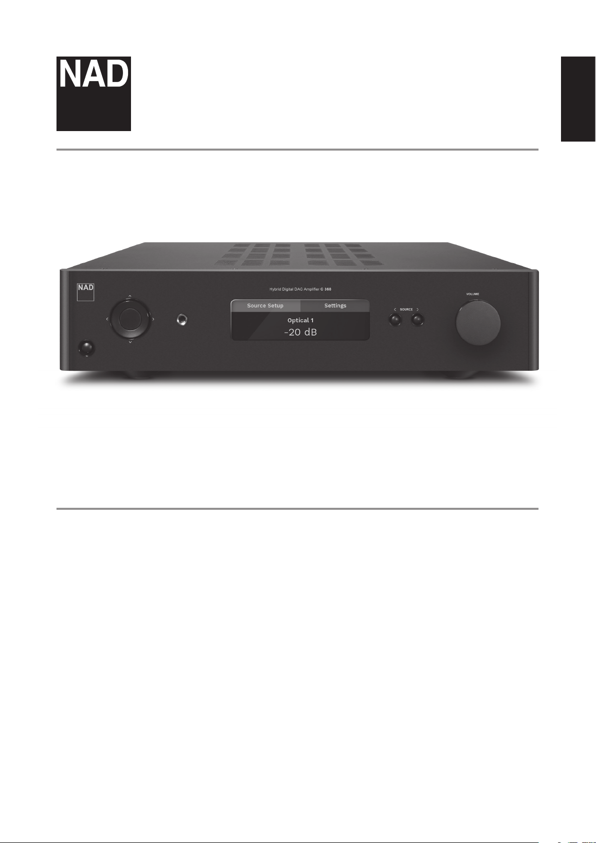
C 368
Hybrid Digital DAC Amplier
ENGLISHFRANÇAISESPAÑOLITALIANODEUTSCHNEDERLANDSSVENSKAРУССКИЙ
Owner’s Manual
IMPORTANT SAFETY INSTRUCTIONS
ENGLISH FRANÇAIS ESPAÑOL ITALIANO DEUTSCH NEDERLANDS SVENSKA РУССКИЙ
1. Read instructions - All the safety and operating instructions should be read
before the product is operated.
2. Retain instructions - The safety and operating instructions should be retained
for future reference.
3. Heed Warnings - All warnings on the product and in the operating instructions
should be adhered to.
4. Follow Instructions - All operating and use instructions should be followed.
5. Cleaning - Unplug this product from the wall outlet before cleaning. Do not use
liquid cleaners or aerosol cleaners. Use a damp cloth for cleaning.
6. Attachments - Do not use attachments not recommended by the product
manufacturer as they may cause hazards.
7. Water and Moisture - Do not use this product near water-for example, near a
bath tub, wash bowl, kitchen sink, or laundry tub; in a wet basement; or near a
swimming pool; and the like.
8. Accessories - Do not place this product on an unstable cart, stand, tripod,
bracket, or table. The product may fall, causing serious injury to a child or adult
and serious damage to the product. Use only with a cart, stand, tripod, bracket,
or table recommended by the manufacturer, or sold with the product. Any
mounting of the product should follow the manufacturer’s instructions, and
should use a mounting accessory recommended by the manufacturer.
9. Cart - A product and cart combination should be moved with care.
Quick stops, excessive force, and uneven surfaces may cause the
product and cart combination to overturn.
10. Ventilation - Slots and openings in the cabinet are provided for ventilation
to ensure reliable operation of the product and to protect it from overheating.
These openings must not be blocked or covered. The openings should never be
blocked by placing the product on a bed, sofa, rug, or other similar surface. This
product should not be placed in a built-in installation such as a bookcase or rack
unless proper ventilation is provided or the manufacturer’s instructions have been
adhered to.
11. Power Sources - This product should be operated only from the type of power
source indicated on the marking label and connected to a MAINS socket outlet
with a protective earthing connection. If you are not sure of the type of power
supply to your home, consult your product dealer or local power company.
12. Power-Cord Protection - Power-supply cords should be routed so that they are
not likely to be walked on or pinched by items placed upon or against them,
paying particular attention to cords at plugs, convenience receptacles, and the
point where they exit from the product.
13. Mains Plug - Where the mains plug or an appliance coupler is used as the
disconnect device, the disconnect device shall remain readily operable.
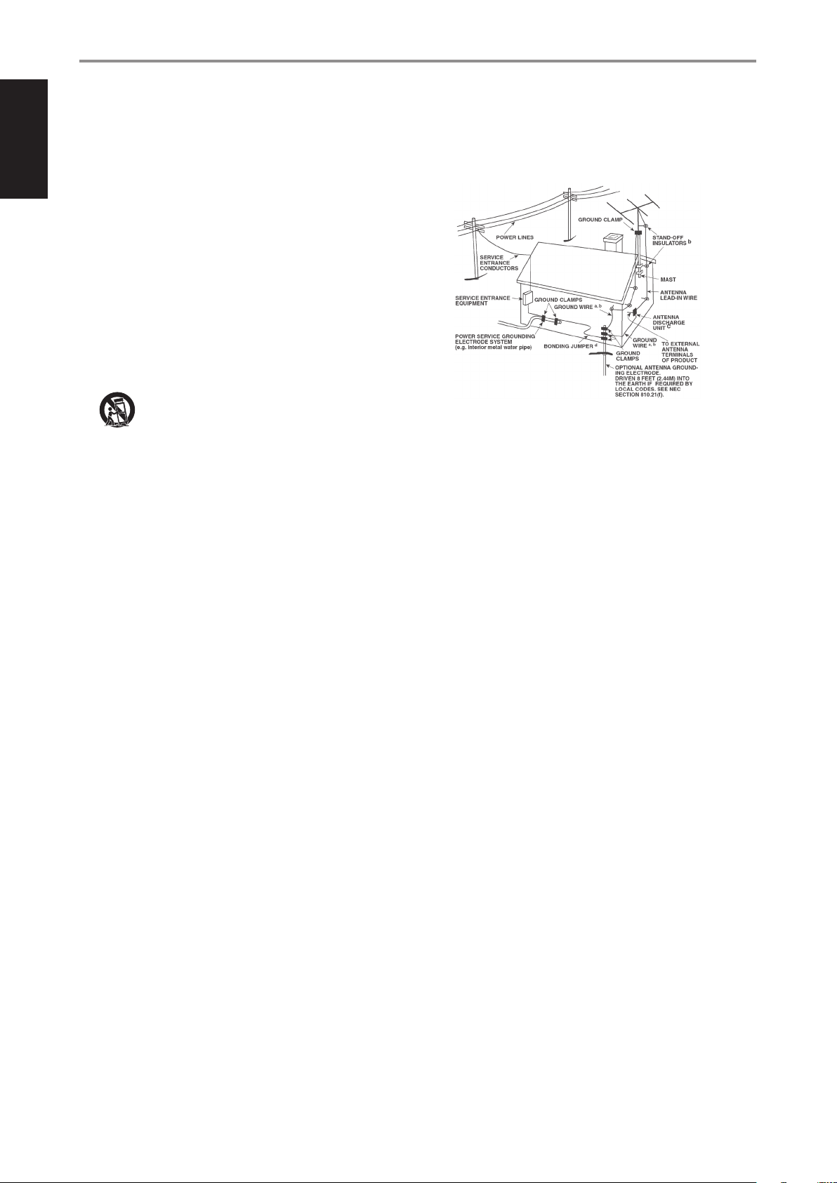
14. Outdoor Antenna Grounding - If an outside antenna or cable system is
connected to the product, be sure the antenna or cable system is grounded so
as to provide some protection against voltage surges and built-up static charges.
Article 810 of the National Electrical Code, ANSI/NFPA 70, provides information
with regard to proper grounding of the mast and supporting structure, grounding
of the lead-in wire to an antenna discharge unit, size of grounding conductors,
location of antenna discharge unit, connection to grounding electrodes, and
requirements for the grounding electrode.
NOTE TO CATV SYSTEM INSTALLER
This reminder is provided to call the CATV system installer’s attention to Section
820-40 of the NEC which provides guidelines for proper grounding and, in particular,
species that the cable ground shall be connected to the grounding system of the
building, as close to the point of cable entry as practical.
15. Lightning - For added protection for this product during a lightning storm, or
when it is left unattended and unused for long periods of time, unplug it from the
wall outlet and disconnect the antenna or cable system. This will prevent damage
to the product due to lightning and power-line surges.
16. Power Lines - An outside antenna system should not be located in the vicinity
of overhead power lines or other electric light or power circuits, or where it can
fall into such power lines or circuits. When installing an outside antenna system,
extreme care should be taken to keep from touching such power lines or circuits
as contact with them might be fatal.
17. Overloading - Do not overload wall outlets, extension cords, or integral
convenience receptacles as this can result in a risk of re or electric shock.
18. Flame Sources - No naked ame sources, such as lighted candles, should be
placed on the product.
19. Object and Liquid Entry - Never push objects of any kind into this product
through openings as they may touch dangerous voltage points or short-out parts
that could result in a re or electric shock. Never spill liquid of any kind on the
product.
20. Headphones - Excessive sound pressure form earphones and headphones can
cause hearing loss.
21. Damage Requiring Service - Unplug this product from the wall outlet and refer
servicing to qualied service personnel under the following conditions:
a. When the power-supply cord or plug is damaged.
b. If liquid has been spilled, or objects have fallen into the product.
c. If the product has been exposed to rain or water.
d. If the product does not operate normally by following the operating
instructions. Adjust only those controls that are covered by the operating
instructions as an improper adjustment of other controls may result in
damage and will often require extensive work by a qualied technician to
restore the product to its normal operation.
e. If the product has been dropped or damaged in any way.
f. When the product exhibits a distinct change in performance-this indicates a
need for service.
22. Replacement Parts - When replacement parts are required, be sure the service
technician has used replacement parts specied by the manufacturer or have the
same characteristics as the original part. Unauthorized substitutions may result in
re, electric shock, or other hazards.
2
IMPORTANT SAFETY INSTRUCTIONS
23. Battery Disposal - When disposing of used batteries, please comply with
governmental regulations or environmental public instruction’s rules that apply in
your country or area.
24. Safety Check - Upon completion of any service or repairs to this product, ask the
service technician to perform safety checks to determine that the product is in
proper operating condition.
25. Wall or Ceiling Mounting - The product should be mounted to a wall or ceiling
only as recommended by the manufacturer.
WARNING
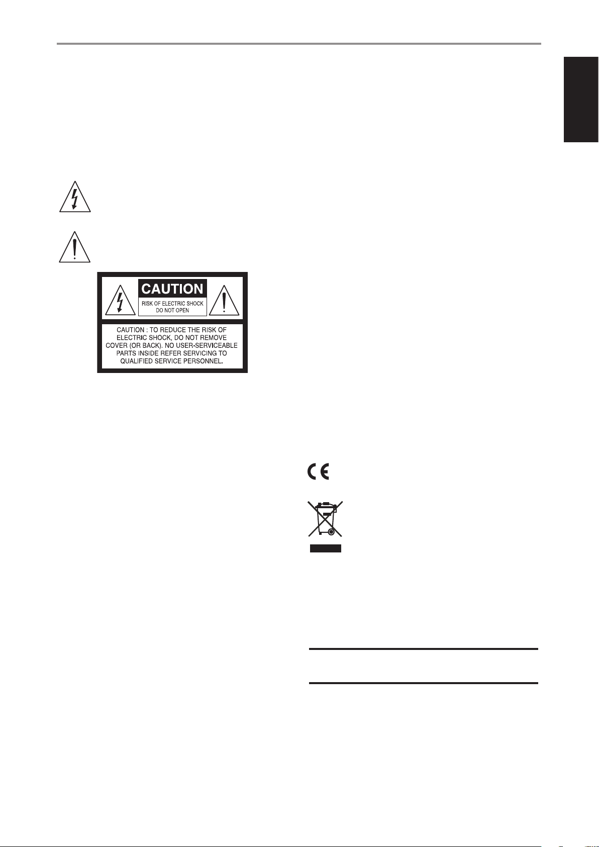
The lightning ash with arrowhead symbol, within an equilateral
triangle, is intended to alert the user to the presence of uninsulated
“dangerous voltage” within the product’s enclosure that may be of
sucient magnitude to constitute a risk of electric shock to persons
The exclamation point within an equilateral triangle is intended to alert
the user to the presence of important operating and maintenance
(servicing) instructions in the literature accompanying the appliance.
CAUTION
• Changes or modications to this equipment not expressly approved by NAD
Electronics for compliance could void the user’s authority to operate this
equipment.
• This device complies with Part 15 of the FCC Rules / Industry Canada licenceexempt RSS standard(s). Operation is subject to the following two conditions:
1 This device may not cause harmful interference, and
2 This device must accept any interference received, including interference that
may cause undesired operation.
• Under Industry Canada regulations, this radio transmitter may only operate
using an antenna of a type and maximum (or lesser) gain approved for the
transmitter by Industry Canada. To reduce potential radio interference to other
users, the antenna type and its gain should be so chosen that the equivalent
isotropically radiated power (e.i.r.p.) is not more than that necessary for successful
communication.
• To prevent electric shock, match wide blade of plug to wide slot, fully insert.
• Marking and rating plate can be found at the rear panel of the apparatus.
• To reduce the risk of re or electric shock, do not expose this apparatus to rain or
moisture. The apparatus shall not be exposed to dripping or splashing and that
no objects lled with liquids, such as vases, shall be placed on apparatus.
• Mains plug is used as disconnect device and it should remain readily operable
during intended use. In order to disconnect the apparatus from the mains
completely, the mains plug should be disconnected from the mains socket outlet
completely.
• Battery shall not be exposed to excessive heat such as sunshine, re or the like.
• Danger of explosion if battery is incorrectly replaced. Replace only with the same
or equivalent type.
• An appliance with a protective earth terminal should be connected to a mains
outlet with a protective earth connection.
ENGLISHFRANÇAISESPAÑOLITALIANODEUTSCHNEDERLANDSSVENSKAРУССКИЙ
THE EQUIPMENT MUST BE CONNECTED TO AN EARTHED MAINS SOCKET-OUTLET.
CAUTION REGARDING PLACEMENT
To maintain proper ventilation, be sure to leave a space around the unit (from the
largest outer dimensions including projections) than is equal to, or greater than
shown below.
Left and Right Panels: 10 cm
Rear Panel: 10 cm
Top Panel: 10 cm
FCC STATEMENT
This equipment has been tested and found to comply with the limits for Class
B digital device, pursuant to Part 15 of the FCC Rules. These limits are designed
to provide reasonable protection against harmful interference in a residential
installation. This equipment generates, uses, and can radiate radio frequency
energy and, if not installed and used in accordance with the instructions, may cause
harmful interference to radio communications. However, there is no guarantee that
interference will not occur in a particular installation. If this equipment does cause
harmful interference to radio or television reception, which can be determined
by turning the equipment o and on, the user is encouraged to try to correct the
interference by one or more of the following measures:
• Reorient or relocate the receiving antenna.
• Increase the separation between the equipment and receiver.
• Connect the equipment into an outlet on a circuit dierent from that to which
the receiver is connected.
• Consult the dealer or an experienced radio TV technician for help.
MPE REMINDER
To satisfy FCC/IC RF exposure requirements, a separation distance of 20 cm or more
should be maintained between the antenna of this device and persons during
device operation. To ensure compliance, operations at closer than this distance is not
recommended.
IF IN DOUBT CONSULT A COMPETENT ELECTRICIAN.
This product is manufactured to comply with the radio interference
requirements of EEC DIRECTIVE 2004/108/EC.
NOTES ON ENVIRONMENTAL PROTECTION
At the end of its useful life, this product must not be disposed of with
regular household waste but must be returned to a collection point for
the recycling of electrical and electronic equipment. The symbol on the
product, user’s manual and packaging point this out.
The materials can be reused in accordance with their markings.
Through re-use, recycling of raw materials, or other forms of recycling of old products,
you are making an important contribution to the protection of our environment.
Your local administrative oce can advise you of the responsible waste disposal point.
RECORD YOUR MODEL NUMBER NOW, WHILE YOU CAN SEE IT
The model and serial number of your new C 368 are located on the back of the
cabinet. For your future convenience, we suggest that you record these numbers here:
Model number : ..........................................
Serial number : ...........................................
NAD is a trademark of NAD Electronics International, a division of Lenbrook Industries Limited
Copyright 2017, NAD Electronics International, a division of Lenbrook Industries Limited
3

INTRODUCTION
GETTING STARTED
ENGLISH FRANÇAIS ESPAÑOL ITALIANO DEUTSCH NEDERLANDS SVENSKA РУССКИЙ
IMPORTANT SAFETY INSTRUCTIONS .........................2
INTRODUCTION
GETTING STARTED ...............................................4
WHAT’S IN THE BOX ..................................................4
CHOOSING A LOCATION .............................................4
RESTORING C 368 TO ITS FACTORY DEFAULT SETTINGS ...............4
IDENTIFICATION OF CONTROLS
FRONT PANEL ....................................................5
REAR PANEL .....................................................6
MDC CLASSIC UPGRADE SLOTS ......................................8
DD HDM1 DIRECT DIGITAL HDMI ..................................8
DD USB 2.0 ...........................................................8
MDC BluOS ...........................................................8
SR 9 REMOTE CONTROL ..........................................9
USING THE SR 9 REMOTE CONTROL ..................................9
USING THE SR 9 REMOTE CONTROL LIBRARY .......................11
NAD REMOTE APP ...............................................12
USING THE NAD REMOTE APP ...................................... 12
OPERATION
USING THE C 368 ................................................13
ACCESS MAIN MENU ...............................................13
NAVIGATING THE MENU OPTIONS AND MAKING CHANGES ........13
SOURCE SETUP ..................................................... 13
ENABLED ........................................................... 13
NAME .............................................................. 13
SETTINGS ........................................................... 13
TONE CONTROLS ................................................... 13
BASS, TREBLE, BALANCE ............................................ 14
FILTERS ............................................................. 14
PRE OUT/SUBWOOFER ............................................. 14
SPEAKER CHANNEL ................................................. 14
TEMPORARY DISPLAY .............................................. 14
DIMMER ............................................................ 15
NETWORK STANDBY. . . . . . . . . . . . . . . . . . . . . . . . . . . . . . . . . . . . . . . . . . . . . . . . 15
AUTO STANDBY ....................................................15
AUTO SENSE .......................................................15
IR CHANNEL ........................................................ 16
IR LEARNING DEVICE ............................................... 16
BT WORK MODE .................................................... 17
C368 AS A BLUETOOTH SINK ....................................... 17
C368 AS A BLUETOOTH SOURCE ................................... 18
VOLUME DISPLAY MODE ...........................................18
FIRMWARE VERSION ................................................19
FIRMWARE UPGRADE ...............................................19
MDC CARD UPGRADE .............................................. 19
BLUOS SETUP ......................................................19
WHAT’S IN THE BOX
Packed with your C 368 you will nd
• Two detachable mains power cord
• SR 9 remote control with 2 AA batteries
• Bluetooth antenna
• Quick Setup Guide
SAVE THE PACKAGING
Please save the box and all of the packaging in which your C 368 arrived.
Should you move or need to transport your C 368, this is the safest
container in which to do so. We’ve seen too many otherwise perfect
components damaged in transit for lack of a proper shipping carton so,
please: Save that box!
CHOOSING A LOCATION
Choose a location that is well ventilated (with at least several inches to
both sides and behind), and that will provide a clear line of sight, within
25 feet / 8meters, between the C 368’s front panel and your primary
listening/viewing position—this will ensure reliable infrared remote control
communications. The C 368 generates a modest amount of heat, but
nothing that should trouble adjacent components.
RESTORING C 368 TO ITS FACTORY DEFAULT SETTINGS
Press and hold both front panel’s a SOURCE s buttons until the display
shows “FACTORY RESET”. Release both a SOURCE s buttons afterwards.
REFERENCE
SPECIFICATIONS ................................................20
4
IDENTIFICATION OF CONTROLS
FRONT PANEL
NA
D
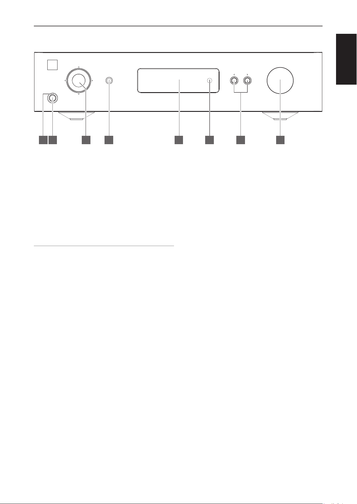
1 POWER INDICATOR
• This indicator will be amber when the C 368 is in standby mode.
• When the C 368 is powered up from standby mode, this indicator
will change from amber to blue color.
2 STANDBY BUTTON
• Press Standby button to switch ON the C 368 from standby mode.
The Power indicator will change from amber to blue color.
• Pressing Standby button again switches back C 368 to standby
mode. The Power indicator will change from blue to amber color.
• The Standby button cannot activate the C 368 if the rear panel
POWER switch is o.
IMPORTANT NOTES
For the Standby button to activate, the following must occur:
a The supplied power cord from the C 368 must be plugged in to a power
source.
b The rear panel POWER switch must be set to ON.
Hybrid Digital DAC Amplifier C 368
5 DISPLAY
• Show visual and menu information according to the selected
• The following Main menu options are shown in the display - Source
• Use the SR 9 remote control or front panel navigation [d/f/a/s]
6 REMOTE SENSOR
• Point the SR 9 remote control at the remote sensor and press the
• Do not expose the remote sensor of the C 368 to a strong light
Distance: About 23ft (7m) from the front of the remote sensor.
Angle: About 30o in each direction of the front of the remote sensor.
VOLUME
SOURCE
© NAD C368
7 81 2 3 4 65
settings.
Setup, Settings and BluOS Setup (available if MDC BluOS module is
installed).
and [ENTER] buttons to go through menu options and selections.
buttons.
source such as direct sunlight or illumination. If you do so, you may
not be able to operate the C 368 with the remote control.
ENGLISHFRANÇAISESPAÑOLITALIANODEUTSCHNEDERLANDSSVENSKAРУССКИЙ
3 NAVIGATION AND ENTER BUTTONS
• The navigation [d/f/a/s] and [ENTER] buttons are used to go
through menu options and selections.
• Use [d/f/a/s] to go up, down, left or right given options or
selections.
• The middle round button is designated as [ENTER] button. This is
normally pressed to complete a selection, procedure, sequence or
other applicable functions.
4 HEADPHONE
• A 1/4” stereo jack socket is supplied for headphone listening and
will work with conventional headphones of any impedance.
• The volume, tone and balance controls are operative for
headphone listening. Use a suitable adapter to connect
headphones with other types of sockets, such as 3.5mm “personal
stereo” jack plugs.
7 a SOURCE s
• Press a SOURCE or SOURCE s to select Sources.
8 VOLUME
• The VOLUME control adjusts the overall loudness of the signal sent
to the loudspeakers. The Volume control is characterized by perfect
signal tracking and channel balance. It provides a highly linear and
low noise operation.
• Turn clockwise to increase the volume level and counter clockwise
to lower it.
• The default volume level is -20 dB.
• If the volume level is higher than -20 dB when the unit goes into
standby mode, either via the front panel Standby button, the SR9
remote’s Power O button, or the unit’s auto standby settings,
then when the unit wakes up the volume level will be reset to the
default -20 dB. If, however, the volume level is lower than -20 dB
when the unit goes into standby mode, that level setting will be
preserved when the unit wakes up.
5
ENGLISH FRANÇAIS ESPAÑOL ITALIANO DEUTSCH NEDERLANDS SVENSKA РУССКИЙ
IDENTIFICATION OF CONTROLS
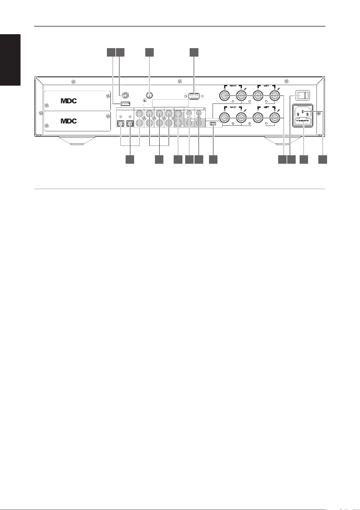
REAR PANEL
11 12 13 14
A
BRIDGE MODE
B
BRIDGE MODE
LEFT
LEFT
POWER
100-120V/220-240V~50/60Hz
ON
© NAD C368
M o d u l a r
D e s i g n
C o n s t r u c t i o n
M o d u l a r
D e s i g n
C o n s t r u c t i o n
ANTENNA
SERVICE
OPTICAL IN
1
BT
Serial No./N de serie
COAXIAL IN
12L
2
GND
PHONO IN
MM
R
LINE 1 IN
LINE 2 IN
L
R R
PRE-OUT/SUBW
L
RIGH T
SPEAKERS
RS232
RIGH T
IR
TRIGGER +12V
IN
L
R
IN
BRIDGE MODE
OUT
OFF ON
(STEREO)
(MONO)
SPEAKERS
761 2 3 4 5 8 9 10
ATTENTION!
Please ensure that the C 368 is powered o or unplugged from the main power source before making any connections. It is also advisable to power down
or unplug all associated components while making or breaking any signal or AC power connections.
1 COAX 1-2, OPT 1-2
• Connect to the corresponding optical or coaxial digital output of
sources such as CD or BD/DVD players, digital cable box, digital
tuners and other applicable components.
4 IR IN/IR OUT
• These mini-jacks accept and output remote-controlled codes in
electrical format, using industry-standard protocols, for use with
“IR-repeater” and multi-room systems and related technologies.
• All NAD products with IR IN/IR OUT features are fully compatible
2 PHONO IN, LINE 1-2 IN
PHONO: Input for a Moving Magnet (MM) phono cartridge. Connect
the twin RCA lead from your turntable to this input if you are using a
with the C 368. For non-NAD models, please check with your other
product’s service specialists with respect to their compatibility to
the C 368’s IR features.
Moving Magnet cartridge.
LINE1, LINE 2: Input for line level sources such as CD player, tuner or
any compatible devices. Use a twin RCA-to-RCA lead to connect the
source device’s left and right “Audio Output” to this input.
IR IN
• This input is connected to the output of an IR (infrared) repeater
(Xantech or similar) or the IR output of another compatible device
to allow control of the C 368 from a remote location.
3 PRE-OUT/SUBW
• These output terminals have dual function. They are used either as
PRE-OUT or SUBWOOFER terminals.
• The C 368 and associated external devices must be turned OFF
always before connecting or disconnecting anything to the PRE-
IR OUT
• Connect IR OUT to the IR IN jack of a compatible device.
• Command and control the linked compatible device by directing its
own remote control to C 368’s infrared receiver.
OUT/SUBW sockets.
5 TRIGGER +12V
PRE-OUT
• The PRE OUT/SUBW sockets make it possible to use the C 368 as a
full range preamplier to an external power amplier.
• Use dual RCA cable to connect PRE-OUT/SUBW to the
corresponding analog audio input of compatible devices such as
ampliers, receivers or other applicable devices.
• PRE-OUT/SUBW will be aected by the C 368’s volume control
settings. Turn the VOLUME control to adjust the output level of the
+12V TRIGGER OUT
• The +12V TRIGGER OUT is used for controlling external equipment
equipped with a +12V trigger input.
• Connect this +12V TRIGGER OUT to the other equipment’s
corresponding +12V DC input jack using a mono cable with 3.5mm
male plug.
• This output will be 12V when the C 368 is ON and 0V when it is
either OFF or in standby mode.
PRE OUT/SUBW sockets.
+12V TRIGGER IN
SUBWOOFER
• Use a dual RCA cable to connect PRE OUT/SUBW to the low level
input of a powered subwoofer.
• Low frequency information up to 150 Hz is sent to the connected
subwoofer via PRE-OUT/SUBW. This is based from 2nd order
Linkwitz-Riley Crossover Filter @150 Hz.
• With this input triggered by a 12V DC supply, the C 368 can be
switched ON remotely from standby mode by compatible devices
such as ampliers, preampliers, receivers, etc. If the 12V DC supply
is cut o, the C 368 will return to standby mode.
• Connect this +12V Trigger input to the remote device’s
corresponding +12V DC output jack using a mono cable with
3.5mm male plug. The controlling device must be equipped with a
+12V trigger output to use this feature.
6
IDENTIFICATION OF CONTROLS
REAR PANEL
NOTE
If there is a stereo jack connected to +12V TRIGGER IN, the C 368 cannot be
powered ON/OFF using the front panel Standby button or SR 9’s ON/OFF
buttons. The stereo jack has to be unplugged to resume normal powering
up of the unit via front panel Standby button or SR 9’s ON/OFF buttons.
6 BRIDGE MODE
The C 368 amplier can be congured to be MONO (Bridge Mode),
more than doubling its output power. This way, the C 368 can be used
as part of a high power stereo or home-theatre system, by connecting
additional power ampliers.
• In BRIDGED MODE (switch at ON (MONO) setting), the C 368 will
produce approximately 300W into an 8 ohm loudspeaker. In this
mode, the amplier sections will react as though the speaker
impedance has been halved. Low impedance speakers (under 8
ohms) are not recommended when using Bridge Mode as these
may cause the amplier’s thermal cut-out to operate if played at
high levels.
• Set the BRIDGE MODE switch to the “ON (MONO)” position and
connect the speaker to the terminals marked “L +” and “R-” ensuring
that the “L+” is connected to the “+” terminal of your speaker and
the “R-” is connected to the speaker’s “ - ” terminal.
• Connect the source to the Left input sockets only. Do not connect
anything to the Right Input socket when Bridge Mode is selected.
7 SPEAKERS
• The C 368 has two sets of SPEAKER connections which are identical
in function (parallel connection).
• Connect C 368’s Right speaker terminals marked “R +” and “R-” to
the corresponding “+” and “-“ terminals of your designated right
speaker. Repeat the same for C 368’s Left speaker terminals and
corresponding left speaker.
• Double check the speaker connections before powering up the
C 368.
9 FUSE HOLDER
• Only qualied NAD service technicians can have access to this fuse
holder. Opening this fuse holder may cause damage thus voiding
the warranty of your C 368.
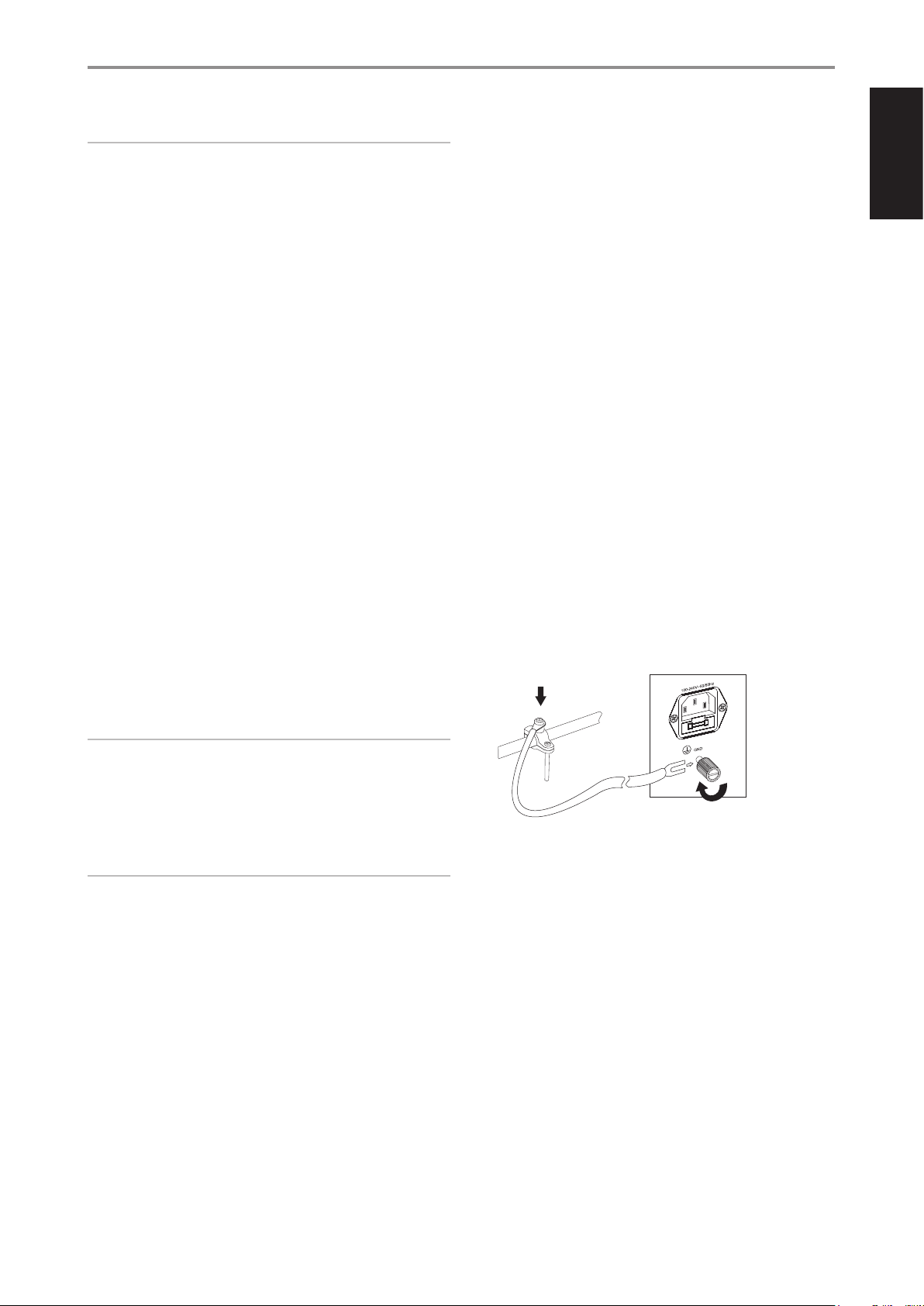
10 AC MAINS INPUT
• The C 368 comes supplied with two separate mains power cords.
Select the mains power cord appropriate for your region.
• Before connecting the plug to the mains power source, ensure that
it is rmly connected to the C 368’s AC Mains input socket.
• Always disconnect the mains power plug from the mains power
source before disconnecting the cable from the C 368’s AC Mains
input socket.
11 SERVICE
• Use for servicing purposes only. Not for consumer use.
12 BLUETOOTH ANTENNA TERMINAL
• Install supplied Bluetooth antenna to this Bluetooth antenna
terminal.
13 GROUND TERMINAL
• Ensure that the C 368 is plugged-in to a grounded AC wall outlet.
• If necessary, use this ground terminal to connect to ground a
phono or turntable source for PHONO input.
• If a separate earth ground is necessary, use this terminal to ground
your C 368. The C 368 can be connected to ground by connecting
a ground lead wire or similar to this terminal. After insertion, tighten
the terminal to secure the lead.
EXAMPLE ILLUSTRATION OF GROUNDING THE C 368 VIA THE
REAR PANEL GROUND TERMINAL
ENGLISHFRANÇAISESPAÑOLITALIANODEUTSCHNEDERLANDSSVENSKAРУССКИЙ
IMPORTANT NOTES
• The blue terminals must never be connected to ground (earth).
• Never connect the blue terminals together or to any common ground
device.
• Do not connect the output of this amplier to any headphone adapter,
speaker switch or any device that uses common ground for left and
right channels.
NOTES
• Use 16 gauge (American Wire Gauge or AWG) or lower stranded wire.
Connections to the C 368 can be made with banana-type plugs.
• Bare wire or pins can also be used by loosening the terminal’s plastic
nut, making a clean, neat connection and re-tightening. To minimize
the danger of a short circuit, ensure that only 1/2-inch of exposed wire
or pin is used to connect and no loose strands of speaker wire.
8 POWER
• Supplies the AC mains power to the C 368.
• When the POWER switch is set to ON position, the C 368 goes to
standby mode as shown by the amber status condition of the front
panel Power indicator.
• Press the front panel Standby button or SR 9’s remote control’s [ON]
button to switch ON the C 368 from standby mode.
• If you do not intend to use the C 368 for long periods of time (such
as when on vacation), switch o the POWER switch.
• With POWER switched o, neither the front panel Standby button
nor SR 9 remote control’s [ON] button can activate the C 368.
14 RS 232
NAD is a certied partner of AMX and Crestron and fully supports
these external devices. Check out the NAD website for information
about AMX and Crestron compatibility with NAD. See your NAD audio
specialist for more information.
• Connect this interface using RS-232 serial cable (not supplied) to
any Windows compatible PC to allow remote control of the C 368
via compatible external controllers.
• Refer to the NAD website for information about RS232 Protocol
documents and PC interface program.
7

ENGLISH FRANÇAIS ESPAÑOL ITALIANO DEUTSCH NEDERLANDS SVENSKA РУССКИЙ
IDENTIFICATION OF CONTROLS
REAR PANEL
MDC CLASSIC UPGRADE SLOTS
The delivery format of digital content is constantly changing in pure digital
systems like the C 368. Each of these formats typically requires specialized
hardware and software, often with licensed IP and content copy protection.
MDC BluOS
BluOS is a music management software developed by NAD’s sister brand,
Bluesound. Integrating MDC BluOS will add BluOS network and internet
music streaming with advanced music management to your C 368.
To address continuous technological evolution, NAD has placed all digital
interface circuitry of the C 368 on easily upgradable modules, called
Modular Design Construction (MDC). The C 368 has provision for two slots
where MDC upgrade modules can be installed.
The following optional MDC modules can be integrated with the C 368 the DD HDM-1, DD USB 2.0 and the MDC BluOS modules. Remove covers
to install the optional Modular Design Construction (MDC) modules.
Consult with your NAD dealer on how to procure the DD HDM-1,
DDUSB2.0 and MDC BluOS modules and their installations to the C 368.
DD HDM-1 (DIRECT DIGITAL HDMI)
The DD HDM-1 oers three HDMI input terminals and one HDMI output
with video pass through. With DD HDM-1 installed, the C 368 can be the
heart of a “Video 2.0” system using the mandatory 2 channel linear PCM
soundtrack from Blu-ray or DVD to make a compelling high denition
theater presentation. DD HDM-1 is fully 3D video compatible without
surround sound decoding or video processing.
A HDMI OUT: Connect the HDMI Monitor
OUT to a HDTV or projector with HDMI
input.
B HDMI 1 -3: Connect to the HDMI OUT
connectors of source components such
as DVD player, BD player or HDTV satellite/
cable box.
A
B
Refer to the “MDC DD BluOS Mounting Instructions” and” Conguring DD
BluOS” (included with your MDC BluOS package) on how to install and
integrate the MDC BluOS with the C 368.
WARNING!
Before connecting and disconnecting any HDMI cables, both the C 368
and the source must be powered OFF and unplugged from the AC
outlet. Failure to do so may cause permanent damage to equipment
connected via HDMI sockets.
DD USB 2.0
A COMPUTER: Using Type A to Type B
cable connector (not supplied), interface
computer audio to this asynchronous TypeB
USB input to directly stream 24/96 PCM
content from your PC or MAC.
B USB BACK: Connect a USB mass
storage device to this input. Typical USB
mass storage devices compatible with
C 368 include portable ash memory
devices and external hard drives (FAT32
formatted).
A
B
8

IDENTIFICATION OF CONTROLS
SCAN
TUNE
SOURCE
SCAN
TUNE
SOURCE
SCAN
TUNE
SOURCE
USING THE SR 9 REMOTE CONTROL
The SR 9 remote control handset handles the key functions of the C 368 as well as other NAD Stereo
Receivers, Integrated Ampliers and Preampliers. It has additional controls to remotely operate NAD
CD Players, AM/FM Tuners and dedicated AM/FM/DAB Tuners. It will operate up to a distance of
23ft (7m). Alkaline batteries are recommended for maximum operating life. Two AA batteries should
be tted in the battery compartment at the rear of the Remote Control handset. When replacing
batteries, check that they have been put in the right way round, as indicated on the base of the battery
compartment.
NOTE
The remote control handset supplied with the C 368 is of a universal NAD type, designed to operate
several NAD models. Some buttons are applicable only to specic NAD models. Contact your dealer
or NAD audio specialist for assistance.
1 POWER ON & OFF: The SR 9 remote has a separate ON and OFF button. Press the ON button
to switch the unit from Standby to operating mode. Press the OFF button to switch the unit to
Standby mode.
2 DEVICE SELECTOR: A Device Selector button determines only what component the SR 9 will
command; it does not perform any function on the C 368. Press desired Device Selector button
for the applicable buttons to be directed to a “page” of commands relevant to the selected device.
Upon selecting a Device, you can now press the corresponding SR 9 control buttons applicable for
the selected Device.
SR 9 REMOTE CONTROL
1
BLS
OPT 1 OPT 2 COAX 1
3, 4
6
7
COAX 2 PHONO LINE 1
LINE 2 USB BT
SCAN
TUNE
SOURCE
ENGLISHFRANÇAISESPAÑOLITALIANODEUTSCHNEDERLANDSSVENSKAРУССКИЙ
2
5
8
9
10
11
3 INPUT SELECTORS: Refer to the corresponding labels printed in the remote control faceplate
and their respective assigned buttons to make use of these functions. Set the DEVICE SELECTOR to
“AMP” in order to gain access to these buttons.
4 NUMERIC KEYS: The numeric keys allow for direct input of tracks for CD players, and direct
channel/preset access for tuners and receivers.
5 SLEEP: Switch o specic NAD Receiver or Tuner models after a preset number of minutes. This
button control does not apply to C 368.
6 MUTE: Press the [MUTE] button to temporarily switch OFF the sound to the speakers and
headphones. MUTE mode is indicated by the Standby LED indicator ashing for NAD Integrated
Ampliers or “Mute” shown in the VFD of NAD Receivers. For C 368, “Mute” is shown in the display.
Press MUTE again to restore sound. Adjusting the volume level via the SR9 or the front panel
volume knob will automatically release the mute function.
7 SOURCE 5/6: Toggle through the source input selections. If the optional MDC modules are
installed, the source selections will include the sources incorporated in the applicable modules.
8 DIM (for use with NAD Stereo Receiver, Tuner and CD Player): Reduce, turn o or restore
display brightness. Depending on the NAD model, the brightness of the front panel display
will vary when you toggle this button. For C 368, toggle to vary brightness level of the display brighter, normal or dimmer.
SR 9
9

SCAN
TUNE
SOURCE
SCAN
TUNE
SOURCE
SCAN
TUNE
SOURCE
ENGLISH FRANÇAIS ESPAÑOL ITALIANO DEUTSCH NEDERLANDS SVENSKA РУССКИЙ
IDENTIFICATION OF CONTROLS
SR 9 REMOTE CONTROL
9 VOL [ 5/6 ]: Press [ 5/6 ] button to increase or decrease the loudness level. Release the button
when the desired level is reached. For NAD Receivers, the VFD will also show “Volume Up” or
“Volume Down” while pressing SR 9’s VOL [5/6]. For C 368, when VOL [5/6] is pressed, the dB
level shown in the display will correspondingly increase or decrease.
10 SPK A, SPK B: The [SPK A] and [SPK B] buttons engage or disengage the speakers connected
respectively to the Speakers A and Speakers B terminals. Toggle [SPK A] to switch ON or OFF the
speakers connected to the Speaker A terminals. Toggle [SPK B] to switch ON or OFF the speakers
connected to the Speaker B terminals.
11 TONE DFT: Tone controls are enabled or disabled by pressing this button.
CD PLAYER CONTROL (for use with NAD CD Player): Set the DEVICE SELECTOR to “CD” in order to
gain access to these buttons. Some of the control buttons below are applicable only to specic NAD
CD Player models; check the owner’s manual of your NAD CD Player for control button compatibility.
SCAN
TUNE
SOURCE
SCAN [ 7/8 ]: Fast reverse/forward search.
[ k ] : Open or close disc tray.
[ g ] : Stop playback.
[ j ] : Pause playback temporarily.
[ 0 ] : Go to next track/le.
[ 9 ] : Go to beginning of current track/le or to previous track/le.
[ 4 ]: Start playback.
[ A/S/D/F ]: Select through folder list/Select through WMA/MP3 les.
ENTER: Select desired folder or WMA/MP3 le.
DISP: Show playback time and other display information.
RAND: Play tracks/les in random order.
RPT: Repeat track, le or whole disc.
PROG: Enter or exit program mode.
CLEAR: Delete programmed track/le.
CD: Select CD as the active source.
USB: Select USB as the active source.
OPT: Select optical input as the active source.
SRC: Toggle to select desired SRC mode.
SCAN
TUNE
SOURCE
TUNER CONTROL (for use with NAD AM/FM/DAB Tuner): Set the DEVICE SELECTOR to “TUN” in
order to gain access to these buttons. Refer to the corresponding labels printed in the remote control
faceplate and their respective assigned buttons to make use of these functions. Some of the control
buttons below are applicable only to specic NAD Receiver or Tuner models; check the owner’s
manual of your NAD Receiver or Tuner for control button compatibility.
AUTO TUNE: In DAB mode, press this button to automatically scan all available local stations.
TUNE [ 7/8 ] or [ A/S ]: Step up or down between AM or FM frequencies.
PRESET [ 9/0 ] or [ D/F ]: Step up or down between stored radio presets.
AM/FM/DAB: Select AM, FM, DAB or XM band (if applicable).
TUNER MODE: In FM mode, toggle between “FM Mute On” and “FM Mute O”. In DAB mode,
pressing this button will activate Dynamic Range Control (DRC), Station Order or other applicable
DAB menu options.
BLEND: Engage or disengage BLEND feature.
MEMORY: Save current station into preset memory.
DELETE: Press and hold for about 2 seconds and the selected preset memory is erased.
[ A/S ]: In DAB mode, in combination with TUNER MODE or other compatible buttons, toggle
to select through DAB feature options like Dynamic Range Control, Station Order and other
appropriate DAB options.
ENTER: In AM/FM mode, toggle to select Preset or Tune mode. In DAB mode, press and hold to
check signal strength.
INFO: Repeatedly pressing this button will show information as supplied by the current radio
station. The applicable display contents include related DAB display information and RDS
broadcast data.
10

IDENTIFICATION OF CONTROLS
SCAN
TUNE
SOURCE
BluOS PLAYBACK CONTROLS (applies only when an optional MDC BluOS module is installed)
Set DEVICE SELECTOR to BLS and the following control buttons are applicable for BluOS playback
control.
4 : Resume playback from pause mode.
; : Pause current playback.
9 : Skip back to the beginning of current song.
0 : Skip forward to the next song.
REPEAT: Repeat song, playlist, all or repeat o. Refer to BluOS controller app to see repeat mode
indicators.
RANDOM: Play songs/playlist in random order.
USING THE SR 9 REMOTE CONTROL LIBRARY
The SR 9 can store a dierent library of default NAD codes for each of its DEVICE SELECTOR “pages.” If
the original default library does not control your NAD CD player, DVD player or other components,
follow the procedure below to change the library code. Refer as well to the table below for a list of
applicable NAD Library Codes with their corresponding NAD models.
LOAD ANOTHER LIBRARY CODE
Example: Load NAD DVD Player T 517 library codes to SR 9’s “CD” device.
1 Press and hold [CD] in the DEVICE SELECTOR section of SR 9.
2 While holding down the device button (CD), press “2” and “2” using SR 9’s numeric buttons. “22” is
the corresponding library code for T 517.
3 Press [ENTER] while still holding down the device button (CD). The CD device selector will ash
once to indicate that the library input is successful. Both the device selector button (CD) and
[ENTER] can now be released.
SR 9 REMOTE CONTROL
ENGLISHFRANÇAISESPAÑOLITALIANODEUTSCHNEDERLANDSSVENSKAРУССКИЙ
RESET THE SR 9 TO ITS DEFAULT SETTINGS
The SR 9 can be restored to its factory settings, including default libraries, by the following procedures
1 Press and hold [ON] and [DELETE/CLEAR] buttons for about 10 seconds until the AMP device
button lights up.
2 Within two seconds of the AMP device button lighting up, release both buttons. If the reset mode
is successful, the [CD] device button will ash twice.
TABLE OF LIBRARY CODES APPLICABLE TO SR 9 REMOTE CONTROL
LIBRARY
CODE
10 Default library for “AMP” page
11 Zone 2
20 Default library for “CD” page; C 515BEE, C 545BEE, C565BEE
21 T 535, T 585, M55, DVD section of L 54, VISO TWO, VISO FIVE
22 T 513, T 514, T 515, T 517
23 T 587
31 IPD 2
40 Default library for “TUN” page; Tuner section of C 725BEE, T 175, T737, T 747, T 755, T 765, T775, T 785
41 C 422, C 425
42 C 445
NOTE
The SR 9 may not necessarily contain all the control buttons applicable for the above-mentioned
NAD products. Use the prescribed remote control of the specic NAD product for a full compliment
of the applicable remote control buttons.
NAD PRODUCT DESCRIPTION
11

ENGLISH FRANÇAIS ESPAÑOL ITALIANO DEUTSCH NEDERLANDS SVENSKA РУССКИЙ
IDENTIFICATION OF CONTROLS
NAD REMOTE APP
The NAD Remote App transforms your smartphone or tablet into a
powerful controller for app enabled products, including select NAD Hi-Fi
ampliers and digital music streamers. With the NAD Remote App, the
traditional NAD remote control is reinvented with an intuitive user interface
and ability to wirelessly control NAD-connected products.
The NAD Remote App for Android and iOS devices uses your local network
and Bluetooth to control and adjust functions like power, volume, source
selection and device settings. The NAD Remote App supports C 368 via
Bluetooth.
Download the App!
Download the NAD Remote App from the respective App stores of Apple
iOS devices (iPad, iPhone and iPod) and Android devices.
USING THE NAD REMOTE APP
After downloading the NAD Remote App from the App store, ensure that
the following setup conditions for the C 368 are implemented.
• Bluetooth antenna installation/connection is secured and tight.
• Ensure that your C368 is powered up and ready.
• From the selectable front panel “Settings” menu, ensure that “BT Work
Mode” option is set to “Sink”.
Launch the NAD Remote App!
Select your device. For this example, select “NAD C368F22A”.
Use the NAD Remote App in the same manner you operate the SR9
remote control or navigate the various menu options of C368.
12

OPERATION
USING THE C 368
ACCESS MAIN MENU
SettingsSource Setup
Optical 1
-20.0 dB
Press [d] once or repeatedly until “Source Setup” is highlighted. Press a or
s to select other Main menu options - Settings and BluOS Setup (available
if MDC BluOS module is installed).
NAVIGATING THE MENU OPTIONS AND MAKING CHANGES
Navigate through the menu options using the front panel buttons or
corresponding SR 9 buttons.
1 Press [ENTER] to select a menu item. Use [d/f] to move up or down
the Menu items.
2 Repeatedly press [a/s] to scroll through current menu choices, options
or selections.
3 Press [ENTER] to save the selection, settings or changes done on the
current menu. After pressing [ENTER] to nalize a selection, use [d/f]
to move to other menu options/items.
NOTE
Menu option will remain displayed and will only turn o or default to
current Source after 1 minute of non-user interface.
SOURCE SETUP
Source Setup
SettingsSource Setup
Optical 1
NAME
Source Setup
SettingsSource Setup
Optical 1
Name
A new Name maybe assigned to a Source label. For example, if your BD player
is attached to “Optical 1”, it is possible to rename “Optical 1” to “BD Player”.
In order to rename the Source label, select “Name” parameter.
1 While at the selected Source, for example “Optical 1”, press [d/f] to
pick through the alphanumeric selections.
2 Press [s] to move to the next character and at the same time save the
changes done on the current character. The name can be as long as
fourteen characters.
3 Repeat steps 1 and 2 for each character in sequence.
4 Complete the renaming process by pressing the [ENTER] button again
to save the new source’s input name. The new Name will be shown in
the display.
SETTINGS
The “Settings” main menu allows you to congure or show the following
features:
• Tone Controls • Bass
• Treble • Balance
• Filters • Pre Out/Subwoofer
• Speaker Channel • Temporary Display
• Dimmer • Network Standby
• Auto Standby • Auto Sense
• IR Channel • IR Learning Device
• Volume Display Mode • Firmware Version
• Firmware Upgrade • MDC Card Upgrade
• BT Work Mode (available only if MDC BluOS module is not installed)
ENGLISHFRANÇAISESPAÑOLITALIANODEUTSCHNEDERLANDSSVENSKAРУССКИЙ
There are two Source Setup menu items – Enabled and Name. At Source
Setup menu, select the particular Source you want to enable, disable or
rename.
ENABLED
Source Setup
SettingsSource Setup
Optical 1
Enabled
One can enable/disable a Source via this option. This is particularly useful
if only few Sources are used and one directly selects the Source from the
front panel, bypassing unused sources.
On: Enable selected Source.
O: Disable selected Source.
TONE CONTROLS
SettingsSource Setup
Settings
Tone Controls
On
Tone controls allow the boosting or reduction of particular audio
frequencies. The tone control levels, Bass and Treble, can be turned on or
o.
On: Tone control levels are active. At Tone Controls On, Bass and Treble
control levels are available for conguration.
O: Tone controls levels are bypassed. At Tone Controls O, Bass
and Treble control levels become unavailable or turned o from the
Settings menu.
13

ENGLISH FRANÇAIS ESPAÑOL ITALIANO DEUTSCH NEDERLANDS SVENSKA РУССКИЙ
OPERATION
USING THE C 368
BASS, TREBLE, BALANCE
SettingsSource Setup
Settings
PRE OUT/SUBWOOFER
SettingsSource Setup
Settings
Bass
0 dB
+-
SettingsSource Setup
Settings
Treble
0 dB
Bass and Treble controls only aect the low bass and high treble leaving
the critical midrange frequencies free of coloration.
• Use [a/s] to boost or cut Bass or Treble levels within ±7 dB range.
+-
SettingsSource Setup
Settings
Balance
0 dB
Balance control adjusts the relative levels of the left and right speakers.
• Press [s] to shift the balance to the right or [a] to shift the balance to
the left. Use [a/s] also to recover or even out the balance levels.
• “0 dB” level setting provides equal level to the left and right channels.
FILTERS
+-
SettingsSource Setup
Settings
Pre Out/Subwoofer
Pre Out
Pre Out/Subwoofer feature allows you to select the function of the PREOUT or SUBWOOFER terminals.
Pre Out: Congured as Pre Out terminals.
Subwoofer: Congured as Subwoofer terminals.
SPEAKER CHANNEL
SettingsSource Setup
Settings
Speaker Channel
Speaker A
SPEAKER CHANNEL enables you to engage or disengage the speakers
connected respectively to the SPEAKERS A and SPEAKERS B terminals on
the rear panel.
Select “Speaker A” or “Speaker B” individually and then set to “On” or “O”.
On: Selected speaker is enabled.
O: Selected speaker is disabled.
TEMPORARY DISPLAY
SettingsSource Setup
Settings
Temporary Display
Off
Filters
High Pass
Filters provide easy bi-amplication or subwoofer integration by adding the
required lters to redirect bass frequencies to the subwoofer.
High Pass: Low pass signal up to 150 Hz is attenuated and over 150
Hz sent to the speakers. This is based from 2nd order Linkwitz-Riley
Crossover Filter @150 Hz.
IMPORTANT NOTE
If dierent crossover lter settings are required, it is recommended to
use the lters built into the connected external Powered Subwoofer.
Experiment by reversing the polarity of the Subwoofer or use a
combination of lters, for example, the High Pass lter built into the
C 368 and run full range to the Subwoofer and set the Crossover lter
setting on the Subwoofer itself. Note that changing the level can also
change the crossover frequency, so experimentation is the only way to
get an optimal result.
Full Range: Refers to the whole frequency spectrum capability of your
C 368 and speaker system. This is ideally 20 Hz to 20 kHz.
Temporary Display feature enables the display to be turned o temporarily
after 10 seconds of non-user interface.
On: Display is turned o temporarily after 10 seconds of non- user
interface. The Standby LED is also turned o at the same time. Display
and Standby LED are activated once user interface is initiated.
O: Display remains illuminated.
14

OPERATION
USING THE C 368
DIMMER
SettingsSource Setup
Settings
Dimmer
Bright
DIMMER function makes it possible to adjust the brightness level of the
front panel display.
Bright: Above normal level of display brightness.
Normal: Normal level of display brightness.
Dim: Below normal level or dimmer than normal display brightness.
NETWORK STANDBY
SettingsSource Setup
Settings
Network Standby
Off
Network Standby mode maintains network connection at standby mode
with reduced system performance level.
On: Network connection is maintained at standby mode.
O: Network connection is disconnected at standby mode.
Refer also to table below about “OPERATING MODE TRIGGER POINTS”.
AUTO STANDBY
SettingsSource Setup
Settings
Auto Standby
On
Auto Standby feature is an integral feature of C 368 that conforms to
European ecodesign regulations. The C 368 can be setup to automatically
go to standby mode if there is no user interface interaction and no active
source input within 20 minutes.
AUTO SENSE
SettingsSource Setup
Settings
Auto Sense
Off
Auto sense feature enables the C 368 to wake up from standby mode
when triggered by network connected App or active source input.
ON
• Unit wakes up from standby mode when triggered by network
connected App or active source input.
• Except for analog input, the unit will power up to the Source that
activated the unit to operating mode.
• When the unit is triggered by an active analog input, the unit will
always power up to Line 1.
OFF
• Unit remains at standby mode even if it is triggered by network
connected App or active source input.
Refer also to table below about “OPERATING MODE TRIGGER POINTS”.
OPERATING MODE TRIGGER POINTS
SETTINGS OPERATING MODE TRIGGER
Auto Standby: On
Network Standby: On
Auto Sense: On
Auto Standby: On
Network Standby: O
Auto Sense: On
Auto Standby: On
Network Standby: On/O
Auto Sense: O
Unit switches back to operating mode by
• resuming activity at network connected app.
• an active source input.
• pressing front panel Standby button or SR 9 remote
control’s [ON] button.
Unit switches back to operating mode by
• an active source input.
• pressing front panel Standby button or SR 9 remote
control’s [ON] button.
• Unit remains at standby mode even if it is triggered
by network connected App or active source input.
• Unit can only be switched back to operating mode by
pressing front panel Standby button or SR 9 remote
control’s [ON] button.
ENGLISHFRANÇAISESPAÑOLITALIANODEUTSCHNEDERLANDSSVENSKAРУССКИЙ
ON
• C 368 switches to standby mode at lowest power consumption (less
than 0.5W) if there is no user interface interaction and no active source
input within 20 minutes.
OFF
• C 368 remains at operating mode even if there is no user interface
interaction and no active source within 20 minutes.
Refer also to table below about “OPERATING MODE TRIGGER POINTS”.
15

ENGLISH FRANÇAIS ESPAÑOL ITALIANO DEUTSCH NEDERLANDS SVENSKA РУССКИЙ
OPERATION
USING THE C 368
IR CHANNEL
SettingsSource Setup
Settings
IR LEARNING DEVICE
SettingsSource Setup
Settings
IR Channel
Channel 0
The C 368 has the capability to operate via Alternate IR channel. This is
useful if you have two NAD products that can be operated by similar
remote control commands. With alternate IR Channel, two dierent NAD
products can be controlled independently in the same zone by setting
each one to a dierent IR channel.
IR Channel Assignment
The C 368 and the SR 9 remote control must be set to the same channel.
To change the IR Channel on the C 368
While at IR Channel menu, use the [a/s] to select through Channel 0 to
Channel 3. Press [ENTER] to select preferred IR Channel setting. C 368 IR
Channel is defaulted to Channel 0.
To change the IR Channel on the SR 9 remote control
• Include a channel number before the library code. For SR 9, library code
“10” is the default library table for “AMP” device. To select this “AMP”
library table for Channel 0, retain the library code “10” (or “010”).
• If you want to load the “AMP” library table on ”Channel 1” prex the
library code with “1” to indicate association with “Channel 1”. Load then
the “AMP” library table using the code “110”. Repeat the same for MP
(130) and TUNER (140).
SAMPLE SETUP OF TWO NAD PRODUCTS ON THE SAME ZONE
NAD C 368 and NAD C 390DD are both defaulted to Channel 0. If [OFF]
button is pressed on the SR 9 remote control (or AVR 4 remote control for
the C 390DD), both products will go to standby mode. Press [ON] and both
products will power up from standby mode.
To prevent both products from simultaneously going in and out of standby
mode along with other common commands, set each one to a dierent
IR channel. In this setup, we will keep C 390DD and AVR 4 remote control
defaulted to “Channel 0”. As for C 368, we will assign it to “Channel 1”; the
same applies to SR 9.
Set C 368 and SR 9 to “Channel 1” via the following procedure.
IR Learning Device
AMP
IR Learning Device enables any non-NAD remote control learn AMP and BluOS
basic remote control codes. With the learned codes, the congured non-NAD
remote control can now be used to command or operate the C 368.
HOW TO LEARN REMOTE CONTROL CODES
1 Go to IR Learning Device menu. Select either AMP or BLS.
2 Select AMP and the rst Amp Learning Key appears – VOLUME UP.
SettingsSource Setup
Settings
Amp Learning Key
VOLUME UP
3 Press ENTER to select VOLUME UP and initiate learning mode.
SettingsSource Setup
Settings
VOLUME UP
Learning...
4 Direct or point the non-NAD remote control to the IR sensor in the
front panel. Then, press desired button on the non-NAD remote
control where VOLUME UP will be learned. Upon pressing the
designated button, display will turn to “Learned”.
SettingsSource Setup
Settings
VOLUME UP
Learned
5 “VOLUME UP” is now learned into the designated button. Repeat
the same for the other codes to be learned. The same procedure
applies for BLS learning.
C 368
While at “IR Channel” menu, use the [a/s] to go to “Channel 1” setting. Press
[ENTER] to select “Channel 1”.
SR 9
• Press and hold [AMP] in the DEVICE SELECTOR section of the SR 9.
• While holding down the device button [AMP], press “1”, “1” and “0” using
SR 9’s numeric buttons.
• Press [ENTER] while still holding down the device button [AMP]. The
AMP device selector will ash once to indicate that the library input is
successful.
With both C 368 and SR 9 set to “Channel 1”, the C 368 can now be
remotely controlled independent of the C 390DD.
NOTE
Performing a Factory Reset for C368 or SR 9 will restore their respective
IR channel setting to “Channel 0”.
16

OPERATION
USING THE C 368
BT WORK MODE
SettingsSource Setup
Settings
BT Work Mode
Sink
Bluetooth (BT) Work Mode denes the two roles of the C 368 as either a
Bluetooth Sink or a Bluetooth Source.
Sink: Audio stream is received from a Source on the same Bluetooth
network environment.
Source: Audio is streamed or sent to another device (Sink) on the same
Bluetooth network environment.
C368 AS A BLUETOOTH SINK
Set “BT Work Mode” to “Sink”. Initiate pairing of your Bluetooth device with
C 368 by following below procedure.
1 Ensure that the Bluetooth antenna is connected to the BT antenna
terminal at the rear panel.
SettingsSource Setup
Bluetooth(Sink)
Discoverable
2 Select “Bluetooth” as a Source. Display shows “Discoverable”.
3 Using your iOS or Android device, go to Settings – Bluetooth and then
scan for Bluetooth devices.
NOTES ABOUT BLUETOOTH SINK SETTINGS
1 If you turn OFF the Bluetooth connection (not “unpair” or disconnected)
of your Bluetooth device, the display will change to “Connectable”.
When you turn ON again your Bluetooth device, the display remains
“Connectable”.
“Connectable” means only the same or current Bluetooth device can
connect to your C 368. This prevents other Bluetooth devices from
connecting to your C 368 unless current Bluetooth device is unpaired
or disconnected.
2 From the device list of the current Bluetooth device, select again the
unique device ID of your C 368 and connection will be resumed again
(Connected) and playback can be resumed also.
3 For other devices to connect to your C 368 even if current Bluetooth
device is not unpaired or disconnected, press and hold the [ENTER]
button until the display changes from “Connectable” to “Discoverable”.
Any Bluetooth device can then select and connect/pair to the unique
device ID of your C 368.
IMPORTANT
There may be instances your Android or iOS Bluetooth device cannot be
found anymore, cannot connect again or any other similar disconnection/
connection incidences after “Unpair”, “Disconnect ” or “Forget Device”.
Resolve these kinds of occurrence by undertaking the following
• Press and hold [ENTER] button until the display changes from
“Connectable” to “Discoverable”. Your Bluetooth device and others
should then be able to select and connect/pair to the unique device
ID of your C 368.
ENGLISHFRANÇAISESPAÑOLITALIANODEUTSCHNEDERLANDSSVENSKAРУССКИЙ
4 At “Discoverable” mode, the unique device ID of your C 368 is listed or
selectable in the device list of your Bluetooth settings. Pair or connect
your C 368 and Bluetooth device.
5 Upon successful pairing of your Bluetooth device and the C 368, display
will change to “Connected” and then “Playing” when music is played
from your Bluetooth device.
SettingsSource Setup
Bluetooth(Sink)
Connected
SettingsSource Setup
Bluetooth(Sink)
Playing
17

ENGLISH FRANÇAIS ESPAÑOL ITALIANO DEUTSCH NEDERLANDS SVENSKA РУССКИЙ
OPERATION
USING THE C 368
C368 AS A BLUETOOTH SOURCE
Set “BT Work Mode” to “Source”. Ensure that the Bluetooth antenna is
connected to the BT antenna terminal at the rear panel.
1 Select “Bluetooth” as a Source. Display could show any of the following
SettingsSource Setup
Bluetooth(Source)
Connectable
Connectable/Discoverable: C 368 is open to connect or pair with
other Source devices within the same Bluetooth network environment.
By default, no connectable or discoverable Bluetooth devices will be
shown as the unit hasn’t gone to “Inquiring” mode yet.
2 Press and hold ENTER button to set the unit to “Inquiring” mode. The
unit searches for available Bluetooth devices within the same Bluetooth
network environment.
SettingsSource Setup
Bluetooth(Source)
Inquiring
NAD HP70
5 If you would like to disconnect from current Bluetooth device, press
ENTER again. The unit will switch back to “Connectable…” mode with
searchable/connectable Bluetooth devices now shown.
SettingsSource Setup
Bluetooth(Source)
Connectable
NAD HP70
6 Repeat steps 3 and 4 above to select and connect to another Bluetooth
device.
7 Having settled on a Bluetooth Source device, toggle a SOURCE s to
select the source media you would like streamed to the connected
Bluetooth device. For example, if you want to stream audio from
LINE1, select LINE 1 as the active source.
VOLUME DISPLAY MODE
SettingsSource Setup
Settings
Volume Display Mode
Decibel
3 Toggle a or s to select through available Bluetooth sources.
4 Connect to your preferred Bluetooth device by pressing ENTER again.
SettingsSource Setup
Bluetooth(Source)
Connected
NAD HP70
Volume Display Mode gives the user two options on how to display
Volume level. Use a or s to select between “Decibel” and “Percent” Volume
level display mode.
18

OPERATION
USING THE C 368
FIRMWARE VERSION
SettingsSource Setup Settings
Firmware Version
Main:Vx.xx
VFD :Vx.xx
BT :Vx.xx
Firmware version details of Main (MCU), VFD (display) and BT (Bluetooth)
are displayed. “x.xx” above stands for the version number of the particular
rmware item.
FIRMWARE UPGRADE
SettingsSource Setup
Settings
Firmware Upgrade
VFD Upgrade
Select Firmware Upgrade to initiate VFD Upgrade or BT Upgrade. At each
upgrade mode, select “Yes” to start upgrade process or “No” to retain current
rmware.
MDC CARD UPGRADE
SettingsSource Setup
Settings
MDC Card Upgrade
BLUOS SETUP
Settings BluOS SetupSource Setup
BluOs
-20.0 dB
“BluOS Setup” becomes available as one of the Main menu items when an
optional MDC BluOS module is installed in one of the MDC slots in the rear
panel. The following are the BluOS Setup menu options.
IMPORTANT NOTE
The BluOS Setup menu options can be congured only at BluOS source
mode. With other sources, the BluOS Setup menu options can be viewed
only but not congurable.
INFO
Display MAC address, IP address, BluOS version and other related
information about the installed MDC BluOS module.
BluOS REBOOT
Yes: Restart MDC BluOS module.
No: Maintain current settings.
SERVICE MENU
There are two options for Service Menu – BluOS Upgrade and BluOS
Service.
ENGLISHFRANÇAISESPAÑOLITALIANODEUTSCHNEDERLANDSSVENSKAРУССКИЙ
Slot:2 BluOS
MDC CARD UPGRADE identies and shows the MDC modules installed at
the MDC slots in the rear panel.
A software upgrade of an installed MDC module like the DD USB 2.0 can
be initiated via the MDC Card Upgrade menu. Upgrade the installed DD
USB 2.0 by complying with the DD USB 2.0 software upgrade guideline that
comes with the software upgrade le.
NOTE
An installed MDC BluOS module cannot be upgraded in this menu. MDC
BluOS module upgrade can be facilitated via the BluOS app or “BluOS
Setup” menu.
BluOS Upgrade
Ensure that the MDC BluOS is connected wired or wirelessly.
Yes: Initiate BluOS upgrade mode. Upgrade mode will proceed
automatically.
No: Maintain current settings.
BluOS Service
Use for servicing purposes only. This is a feature normally associated
and coordinated with authorized service personnel.
Yes: Activate Service mode. This must be coordinated or
performed by authorized service personnel.
No: Maintain current settings.
BluOS RESET
Initiate the restoration of the MDC BluOS to its factory default settings.
Yes: Initiate factory reset.
No: Maintain current settings.
19

ENGLISH FRANÇAIS ESPAÑOL ITALIANO DEUTSCH NEDERLANDS SVENSKA РУССКИЙ
REFERENCE
SPECIFICATIONS
All specs are measured according to IHF 202 CEA 490-AR-2008 standard. THD is measured using AP AUX 0025 passive lter and AES 17 active lter.
PREAMPLIFIER SECTION
LINE INPUT, PRE OUT
THD (20 Hz – 20 kHz) <0.005 % at 2 V out
Signal-to-Noise Ratio >106 dB (IHF; A-weighted,
ref. 500 mV out, unity gain)
Channel separation >80 dB (1 kHz)
>70 dB (10 kHz)
Input impedance (R and C) 22 kohms + 100 pF
Maximum input signal >4.5 Vrms (ref. 0.1 % THD)
Output impedance Source Z + 240 ohms
Input sensitivity 93 mV
(ref. 500 mV out, Volume maximum)
Frequency response ±0.3 dB (20 Hz - 20 kHz)
Maximum voltage output -IHF load >4.5 V (ref. 0.1 % THD)
Tone controls Treble: ±7.0 dB at 20 kHz
Bass: ±7.0dB at 60 Hz
Balance: -10dB
PHONO INPUT, PRE OUT
THD (20 Hz – 20 kHz) <0.01 % at 2 V out
Signal-to-Noise Ratio >84 dB (200 ohms source;
A-weighted, ref. 500 mV out)
>76 dB (MM cartridge source, IHF;
A-weighted, ref. 500 mV out)
Input sensitivity 1.44 mV
(ref. 500 mV out, Volume maximum)
Frequency response ±0.3 dB (20 Hz - 20 kHz)
Maximum input signal at 1kHz >80 mVrms (ref. 0.1 % THD)
GENERAL SPECIFICATIONS
LINE IN, SPEAKER OUT
Continuous output power into 8 ohms
and 4 ohms
Continuous output power into 8 ohms
(Bridge mode)
THD (20 Hz – 20 kHz) <0.03 %
Signal-to-Noise Ratio >98 dB (A-weighted, 500 mV input,
Clipping power >95 W (at 1 kHz 0.1 % THD)
Clipping power (Bridge mode) >315 W (at 1 kHz 0.1 % THD)
IHF dynamic power 8 ohms: 120 W
IHF dynamic power (Bridge mode) 8 ohms: 500 W
Peak output current >20 A (in 1 ohm, 1 ms)
Damping factor >300 (ref. 8 ohms, 20Hz to 6.5kHz)
Frequency response ±0.3 dB (20 Hz - 20 kHz)
Channel separation >75 dB (1 kHz)
Input sensitivity (for 80 W in 8 ohms) Line In: 470 mV
Supports bit rate/sample rate up to 24 bit/192 kHz
Standby power <0.5 W
Frequency band 2.402G- 2.480G
Maximum transmit power(dBm) 7 dBm ± 2 dBm
80W (ref. 20 Hz-20 kHz at rated THD,
both channels driven)
300W (ref. 20 Hz – 20 kHz at THD 0.03%)
(250 mW to 80 W, 8 ohms and 4 ohms)
ref. 1W out in 8 ohms)
4 ohms: 200 W
2 ohms: 250 W
4 ohms: 560 W
>70 dB (10 kHz)
Digital In: 21% FS
LINE INPUT, HEADPHONE OUT
THD (20 Hz – 20 kHz) <0.005 % at 1V out
Signal-to-Noise Ratio >110 dB (32 ohms loads;
A-WTD, ref. 2V out, unity gain
Frequency response ±0.3 dB (20 Hz - 20 kHz)
Channel separation >60 dB at 1kHz
Output impedance 6 ohms
* - Gross dimension includes feet, volume knob and extended rear panel terminals.
Specifications are subject to change without notice. For updated documentation and features, please check out www.NADelectronics.com for the latest information about C368.
DIMENSION AND WEIGHT
Gross dimensions (W x H x D) 435 x 100 x 390 mm
17 / x 3 / x 15 / inches
Net weight 7.8 kg (17.2 lbs)
Shipping weight 10.1 kg (22.3 lbs)
20

ENGLISHFRANÇAISESPAÑOLITALIANODEUTSCHNEDERLANDSSVENSKAРУССКИЙ
21

www.NADelectronics.com
©2017 NAD ELECTRONICS INTERNATIONAL
A DIVISION OF LENBROOK INDUSTRIES LIMITED
All rights reserved. NAD and the NAD logo are trademarks of NAD Electronics International, a division of Lenbrook Industries Limited.
No part of this publication may be reproduced, stored or transmitted in any form without the written permission of NAD Electronics International.
While every effort has been made to ensure the contents are accurate at the time of publication, features and specifications may be subject to change without prior notice.
C368_ENG_OM_V23 NOV 2017
 Loading...