

MSI MS-6555 User Manual

Getting Started
1-1
Chapter 1. Getting Started
1
Getting Started
Thank you for purchasing the MS-6555 v1.X Micro ATX mainboard. The
MS-6555 is based on Intel® Brookdale-G & ICH4 chipsets for optimal system
efficiency. Designed to fit the advanced Intel® Pentium® 4 processors in the
478 pin package, the MS-6555 delivers a high performance and professional
desktop platform solution.
TOPICS
Mainboard Specification 1-2
Mainboard Layout 1-4
Quick Components Guide 1-5
MSI Special Features 1-6

Chapter 1
1-2
CPU
Supports Intel® Pentium® 4 processor in 478-pin package.
Supports 1.5GHz, 1.6GHz, 1.7GHz, 1.8GHz, 1.9GH z, 2GHz and up.
Chipset
Intel® Brookdale-G/GL chipset
- Integrated video accelerator.
- AGP 4x universal slot (G).
- Support 100/133 MHz FSB.
- Support 400/533 MHz Intel NetBurst micro-architecture bus.
Intel® ICH4 chipset
- 2 channel Ultra ATA 100 bus Master IDE controller.
- PCI Master 2.2.
- I/O APIC.
- AC’97 2.2 interface.
- 3 UHCI Host controllers and 1 EHCI Host controller.
Main Memory
Supports four memory banks using two 184-pin DDR DIMM.
Supports up to 2GB PC2100/PC1600 DDR SDRAMs.
Supports 2.5v DDR SDRAM.
Slots
One AGP(Accelerated Graphics Port) 4x slot (1.5V only).
Three PCI 2.2 32-bit Master PCI bus slots (support 3.3V/5V PCI bus interface).
On-Board IDE
An IDE controller on the ICH4 chipset provides IDE HDD/CD-ROM with
PIO, Bus Master and Ultra DMA66/100 operation modes.
Can connect up to four IDE devices.
On-Board Peripherals
On-Board Peripherals include:
- 1 floppy port supports 2 FDD with 360K, 720K, 1.2M, 1.44M and 2.
88Mbytes.
- 2 serial ports (COMA / COMB)
- 1 parallel port supports SPP/EPP/ECP mode
Mainboard Specification

Getting Started
1-3
- 6 USB 2.0 ports (Rear * 2 / Front * 4)
- PS2 K/B connector
- 1 Line-In/Line-Out/Mic-In/Game port
- 1 RJ45 connector (optional)
Audio
AC97 2.2 interface provided by ICH4
2 channel S/W audio codec
- AC'97 2.2 Compliant
- Meet PC2001 audio performance requirement
LAN (optional)
RealTek RTL8100BL.
BIOS
PnP (Plug & Play) BIOS to detect peripheral devices and expansion cards
automatically.
DMI (Desktop Management Interface) function to record motherboard
specification.
Provide WOL, chassis intrusion and SMBus for system management.
Dimension
Micro-ATX Form Factor (9.6" x 8.82").
Mounting
6 mounting holes.
Others
Modem (External/Internal) Ring Wake Up Function.
LAN Wake Up Function.
Suspend to RAM/Disk.
PC2001 Compliant.
Chapter 1
1-4
AGP Slot
BATT
+
Intel
Brookdale-G/GL
chipset
ICH4
WOM
(optional)
A
T
X
_
P
O
W
E
R
PAN EL1
(optional)
CLR_CMOS
BIOS
PCI S lot 3
PCI S lot 2
PCI S lot 1
I
D
E
1
I
D
E
2
WOL
(optional)
JAUDIO1
IR1
F_AUDIO
(optional)
T:LAN Jack
B:USB ports
Top :
Parallel Port
Bottom:
COM A
VGA Port
Top : mo use
Bottom: keyboar d
JCASE
(optional)
Codec
RTL8100BL
W
i
n
b
o
n
d
8
3
6
2
7
H
F
-
A
W
C
D
_
I
N
2
(
o
p
t
i
o
n
a
l
)
C
D
_
I
N
1
ATX12V
P
W
R
_
F
A
N
C
P
U
_
F
A
N
P
W
R
S
W
1
(
o
p
t
i
o
n
a
l
)
SYS_FAN
Top :
Game port
Bottom:
Line-Out
Line-In
Mic
F
D
D
1
COM 2
D
I
M
M
1
D
I
M
M
2
JFP1
USB3
(optional)
USB4
(optional)
USB1 USB2
L
A
N
_
E
N
(
o
p
t
i
o
n
a
l
)
BIOS_WP
(optional)
CNR
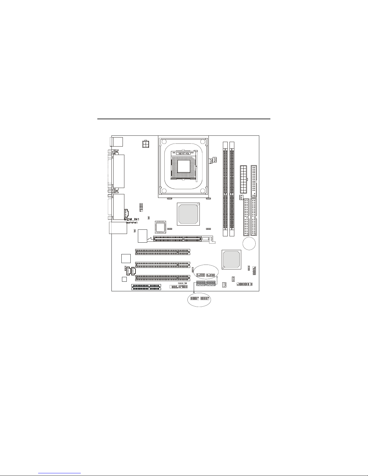
Mainboard Layout
MS-6555 v1.X Micro ATX Mainboard

Getting Started
1-5
Quick Components Guide
Component Function Reference
Socket 478 Installing CPU See p. 2-2
DDR1~2 Installing DDR modules See p. 2-5
ATX Power Connector Installing power supply See p. 2-7
USB Connectors Connecting to USB devices See p. 2-9
COM A & COM 2 Serial port connector See p. 2-10
VGA DB15 Connector Connecting to VGA monitor See p. 2-10
RJ-45 LAN Jack Connecting to LAN devices See p. 2-11
LPT1 Parallel port connector See p. 2-12
FDD1 Floppy disk drive connector See p. 2-13
PWRSW1 Independent power switch See p. 2-13
IDE1~ IDE2 Hard disk connectors See p. 2-14
CDIN1/CDIN2 CD-in connector See p. 2-15
MDM_IN1 Modem-in connector See p. 2-15
CPUFAN1/PWR/SYS_FAN Fan power connectors See p. 2-16
JCASE Chassis intrusion switch See p. 2-17
IR1 IrDA infrared module connector See p. 2-17
WOM1 Wake On Ring connector See p. 2-18
WOL1 Wake On LAN connector See p. 2-18
JFP1 or PANEL1 Front panel connector See p. 2-19
JAUDIO1 or F_AUDIO Front panel audio connector See p. 2-20
USB1/2 or USB3/4 Front USB connector See p. 2-22
CLR_CMOS Clear CMOS jumper See p. 2-23
LAN_EN LAN enable/disable jumper See p. 2-24
AGP Slot Connecting to AGP cards See p. 2-25
PCI Slots Connecting to expansion cards See p. 2-25
Chapter 1
1-6
MSI Special Features
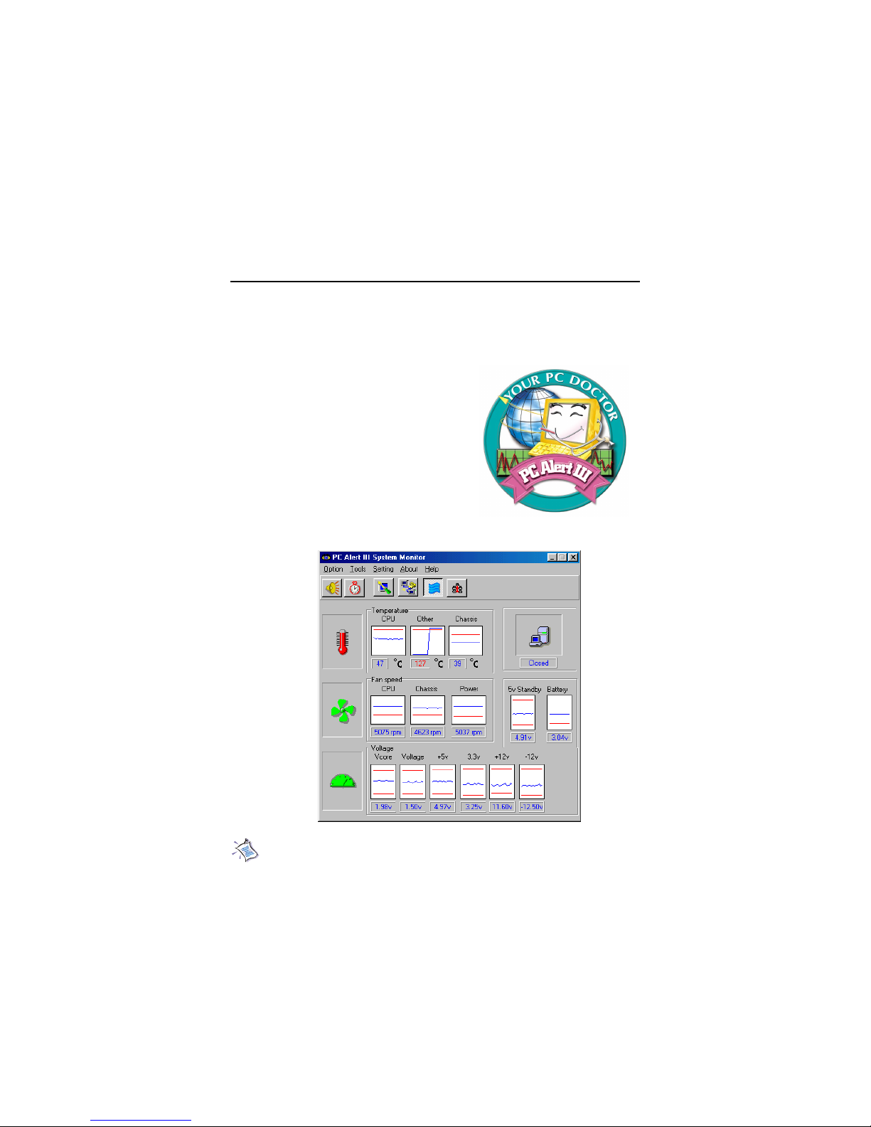
PC Alert™ III
The PC AlertTM III is a utility you can find in the CD-ROM disk. The
utility is just like your PC doctor that can detect the following PC hardware status during
real time operation:
* monitor CPU & system temperatures
* monitor fan speed(s)
* monitor system voltage
* monitor chassis intrusion
If one of the items above is abnormal,
the program main screen will be immediately
shown on the screen, with the abnormal item
highlighted in red. This will continue to be
shown until users disable the warning.
Note: Items shown on PC Alert III vary depending on your system’s
status.

Hardware Setup
2-1
Chapter 2. Hardware Setup
TOPICS
Central Processing Unit: CPU 2-2
Memory 2-5
Power Supply 2-7
Back Panel 2-8
Connectors 2-13
Jumpers 2-23
Slots 2-25
2
Hardware Setup
This chapter provides you with the information about hardware setup
procedures. While doing the installation, be careful in holding the components
and follow the installation procedures. For some components, if you install in
the wrong orientation, the components will not work properly.
Use a grounded wrist strap before handling computer components. Static
electricity may damage the components.
Chapter 2
2-2
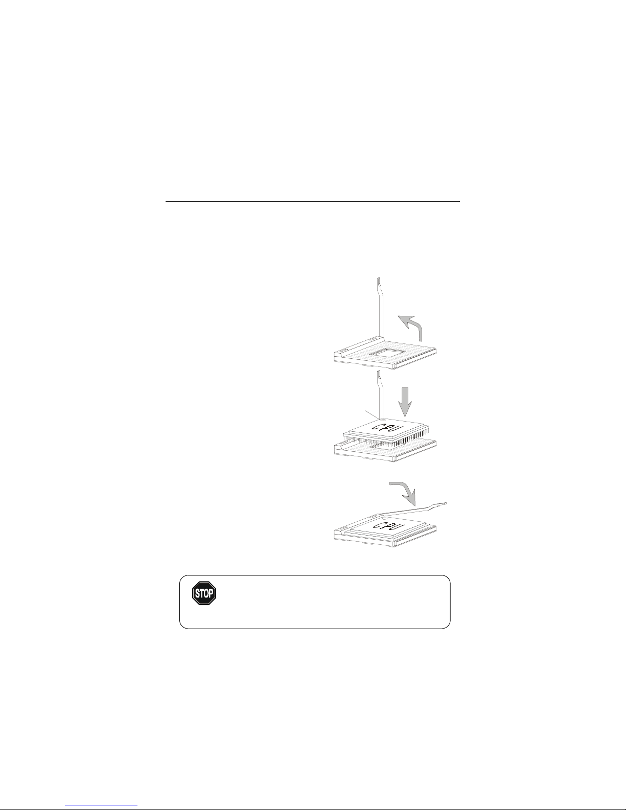
Central Processing Unit: CPU
1. Pull the lever sideways away
from the socket. Then, raise
the lever up to a 90-degree
angle.
2. Look for the dot/cut edge. The
dot/cut edge should point towards the lever pivot. The
CPU will only fit in the correct
orientation.
3. Press the CPU down firmly
into the socket and close the
lever. As the CPU is likely to
move while the lever is being
closed, always close the lever
with your finger pressing
tightly on top of the CPU to
make sure the CPU is properly
& completely embedded into
the socket.
CPU Installation Procedures
Open Lever
Dot / Cut edge
Sliding
Plate
Close
Lever
The mainboard supports Intel® Pentium® 4 processor in the 478 pin
package. The mainboard uses a CPU socket called PGA478 for easy CPU
installation. When you are installing the CPU, make sure the CPU has a heat
sink and a cooling fan attached on the top to prevent overheating. If you do not
find the heat sink and cooling fan, contact your dealer to purchase and install
them before turning on the computer.
Overheating will seriously damage the CPU and system,
always make sure the cooling fan can work properly to
protect the CPU from overheating.
WARNING!

Hardware Setup
2-3
Installing the CPU Fan
As processor technology pushes to faster speeds and higher
performance, thermal management becomes increasingly important. To dissipate heat, you need to attach the CPU cooling fan and heatsink on top of the
CPU. Follow the instructions below to install the Heatsink/Fan:
2. Position the heatsink onto the reten-
tion mechanism.
1. Locate the CPU and its retention
mechanism on the motherboard.
3. Mount the fan on top of the heatsink.
Press down the fan until its four clips
get wedged in the holes of the retention mechanism.
4. Press the two levers down to fasten
the fan. Each lever can be pressed
down in only ONE direction.
retention mechanism
levers
Chapter 2
2-4
CPU Core Speed Derivation Procedure
If CPU Clock = 100MHz
Core/Bus ratio = 1 4
then CPU core speed = Host Clock x Core/Bus ratio
= 100MHz x 14
= 1.4GHz
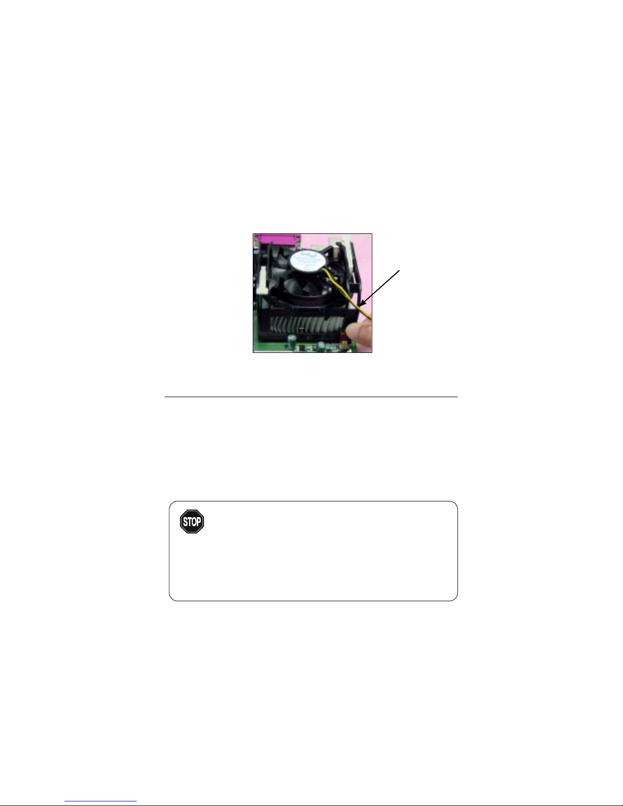
5. Connect the fan power cable from the mounted fan to the 3-pin fan power connector
on the board.
fan power cable
Overclocking
This motherboard is designed to support overclocking.
However, please make sure your components are able to
tolerate such abnormal setting, while doing overclocking.
Any attempt to operate beyond product specifications is not
recommended. We do not guarantee the damages or risks
caused by inadequate operation or beyond product
specifications.
WARNING!
Hardware Setup
2-5
D
I
M
M
1
D
I
M
M
2
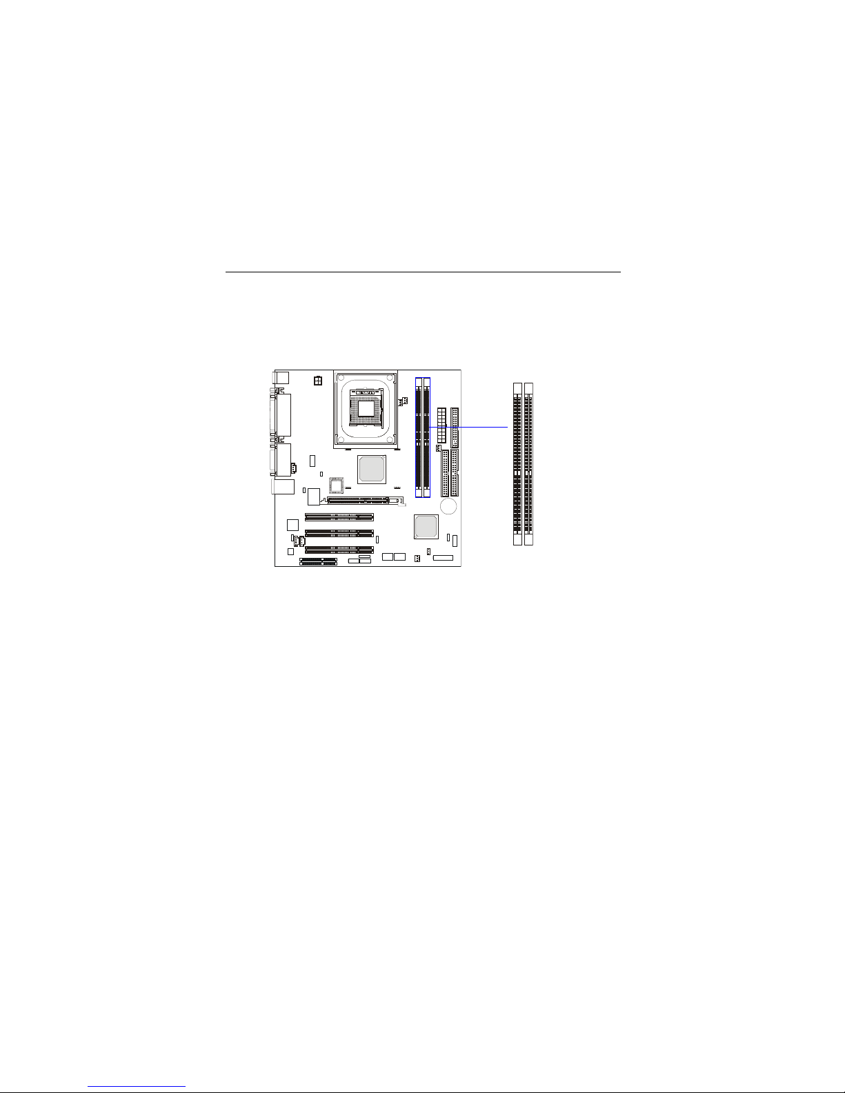
Memory
The mainboard provides 2 slots for 184-pin, 2.5V DDR DIMM with 4
memory banks. You can install DDR200/PC1600 or DDR266/PC2100 DDR
SDRAM modules on the DDR DIMM slots (DDR 1~2). To operate properly, at
least one DIMM module must be installed.
Introduction to DDR SDRAM
DDR (Double Data Rate) SDRAM is similar to conventional SDRAM,
but doubles the rate by transferring data twice per cycle. It uses 2.5 volts as
opposed to 3.3 volts used in SDR SDRAM, and requires 184-pin DIMM modules rather than 168-pin DIMM modules used by SDR SDRAM. Two types of
DDR are available at the time of writing: PC1600 & PC2100. PC1600 DDR SDRAM
running at 100MHz will produce about 1.6GB/s memory bandwidth. PC2100
running at 133MHz will produce 2.1GB/s memory bandwidth. High memory
bandwidth makes DDR an ideal solution for high performance PC, workstations and servers.
Chapter 2
2-6
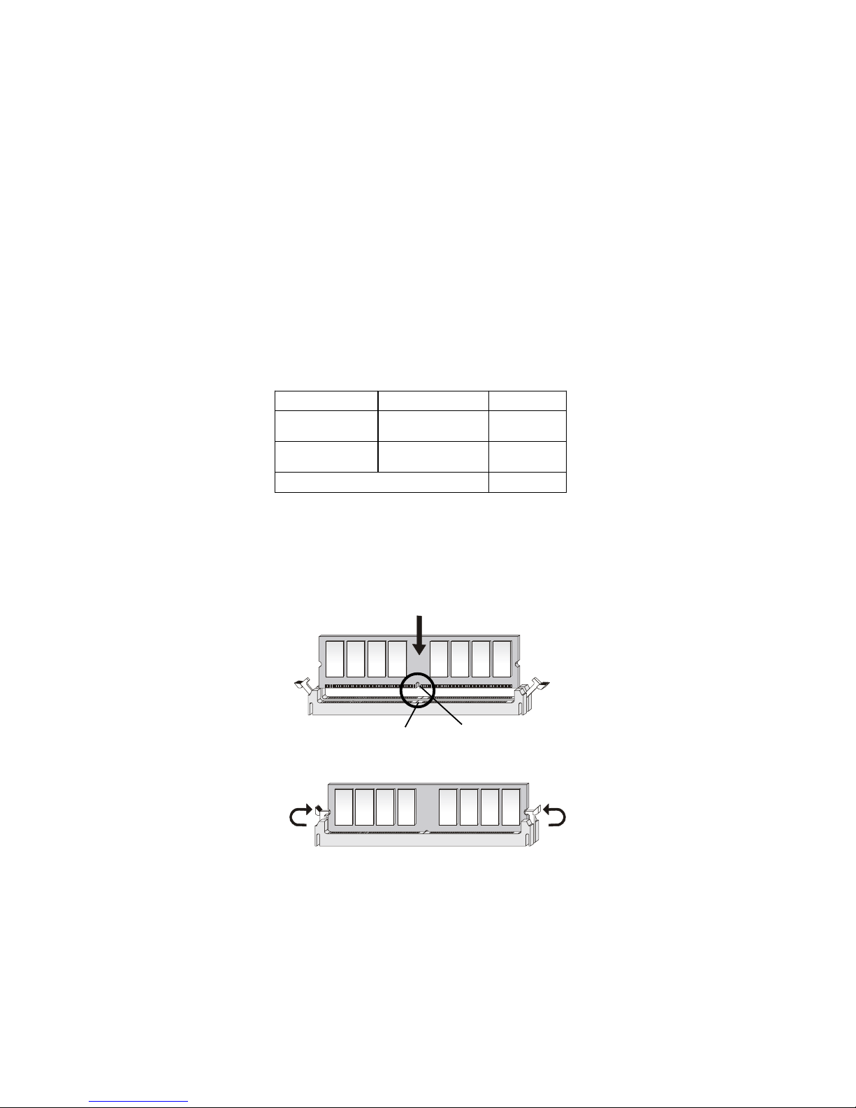
You can install either single sided or double sided 184-pin DDR DIMM
modules into DDR DIMM slots to meet your needs. Different from the SDR
DIMM, the DDR DIMM has only one notch on the center of module. The
number of pins on either side of the breaks are different. The module will only
fit in the right orientation.
Y ou can install memory modules in any combination as follows:
DDR Module Combination
Installing DDR Modules
1. The DDR DIMM has only one notch on the center of module. The module
will only fit in the right orientation.
2. Insert the DIMM memory module vertically into the DIMM slot. Then
push it in.
3. The plastic clip at each side of the DIMM slot will automatically close.
Volt
notch
S: Single Side D: Double Side
Slot Memory Module Total Memory
DIMM 1
(Bank 0 & 1)
S/D 64MB~1GB
DIMM 2
(Bank 2 & 3)
S/D 64MB~1GB
Maximum System Memory Supported
64MB~2GB
Hardware Setup
2-7
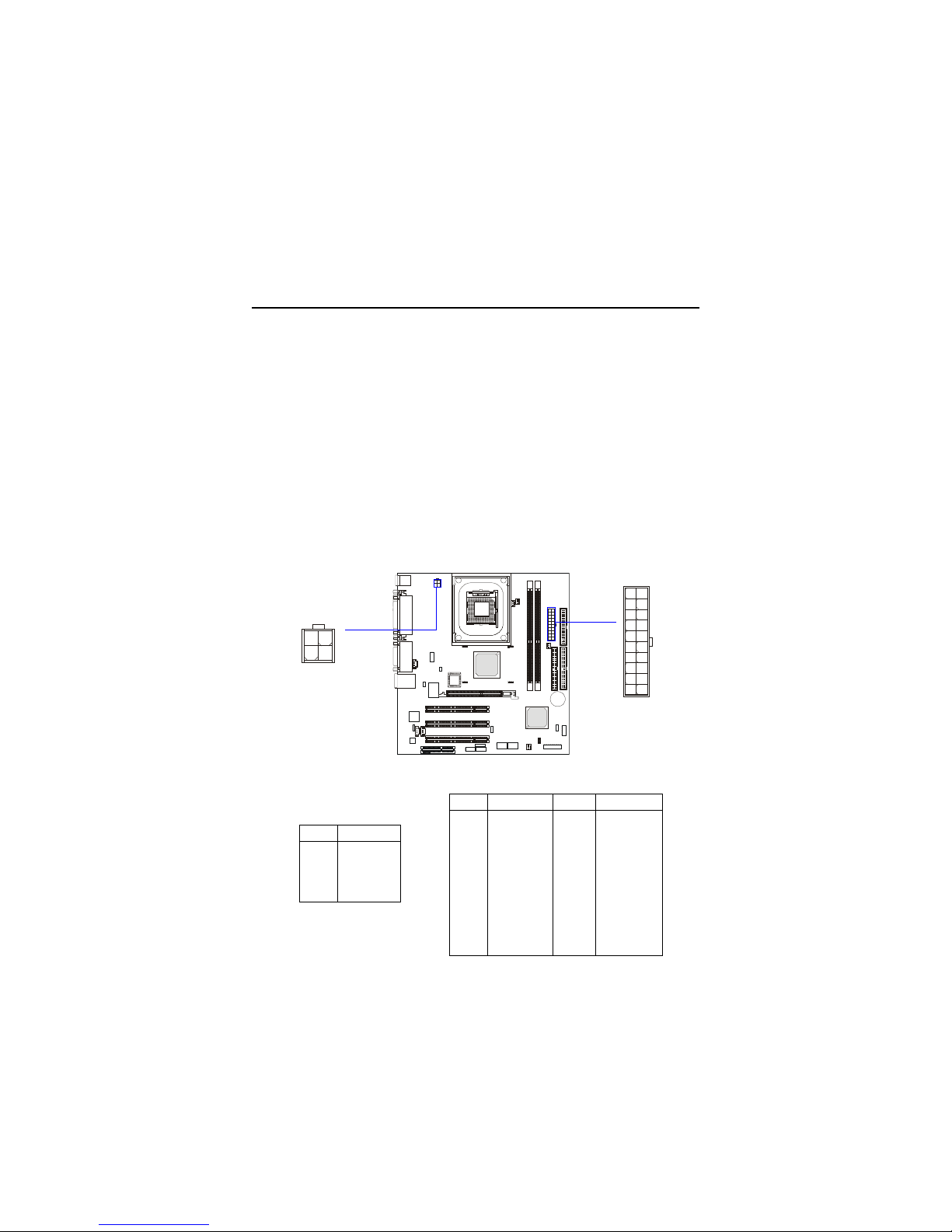
Power Supply
A TX 20-Pin Power Connector: A TX_POWER
This connector allows you to connect to an ATX power supply. To
connect to the ATX power supply, make sure the plugs of the power supply is
inserted in the proper orientation and the pins are aligned. Then push down
the power supply firmly into the connector. The power connector supports
instant power on function which means that system will boot up immediately
when the power supply connector is inserted on the board.
The mainboard supports ATX power supply for the power system. Before inserting the power supply connector, always make sure that all components are installed properly to ensure that no damage will be caused.
A TX 12V Power Connector: A TX12V
This 12V power connector is used to provide power to the CPU.
PIN SIGNAL
1 GND
2 GND
3 12V
4 12V
ATX12V Pin Definition
PIN SIGNAL
1 1 3.3V
12 -12V
13 GND
14 PS_ON
15 GND
16 GND
17 GND
18 -5V
19 5V
20 5V
PIN SIGNAL
1 3.3V
2 3.3V
3 GND
45V
5 GND
65V
7 GND
8 PW_OK
9 5V_SB
10 12V
ATX_POWER Pin Definition
10
1
20
11
ATX_POWER
ATX12V
1 2
3 4
Chapter 2
2-8
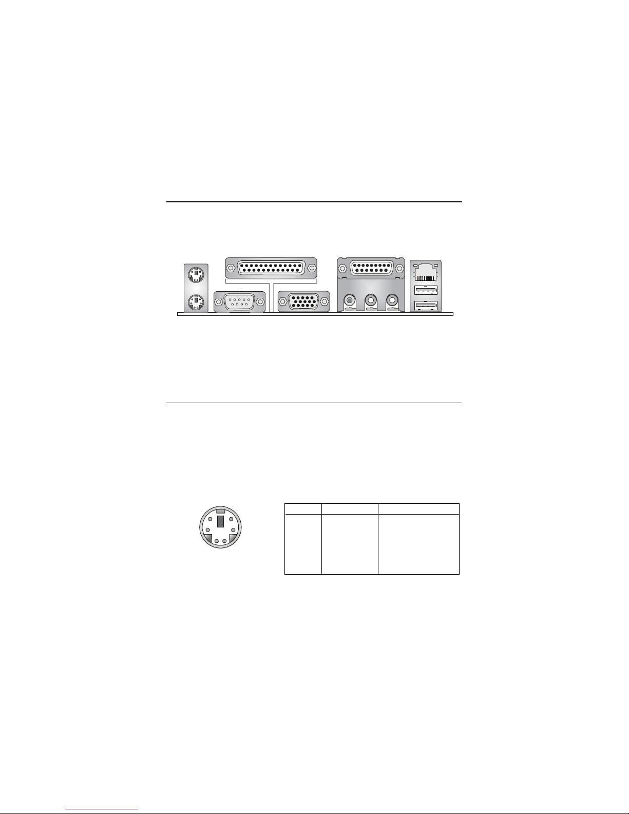
The Back Panel provides the following connectors:
Back Panel
Mouse Connector
The mainboard provides a standard PS/2® mouse mini DIN connector for
attaching a PS/2® mouse. You can plug a PS/2® mouse directly into this
connector. The connector location and pin assignments are as follows:
PIN SIGNAL DESCRIPTION
1 Mouse DATA Mouse DAT A
2 NC No connection
3 GND Ground
4 VCC +5V
5 Mouse Clock Mouse clock
6 NC No connection
Pin Definition
PS/2 Mouse (6-pin Female)
2
1
3
4
5
6
Mouse
Keyboard
USB
Parallel
COM A
L-out L-in MIC
Midi/Joystick
LAN
(optional)
VGA
Hardware Setup
2-9
Keyboard Connector
The mainboard provides a standard PS/2® keyboard mini DIN connector
for attaching a PS/2® keyboard. You can plug a PS/2® keyboard directly into
this connector.
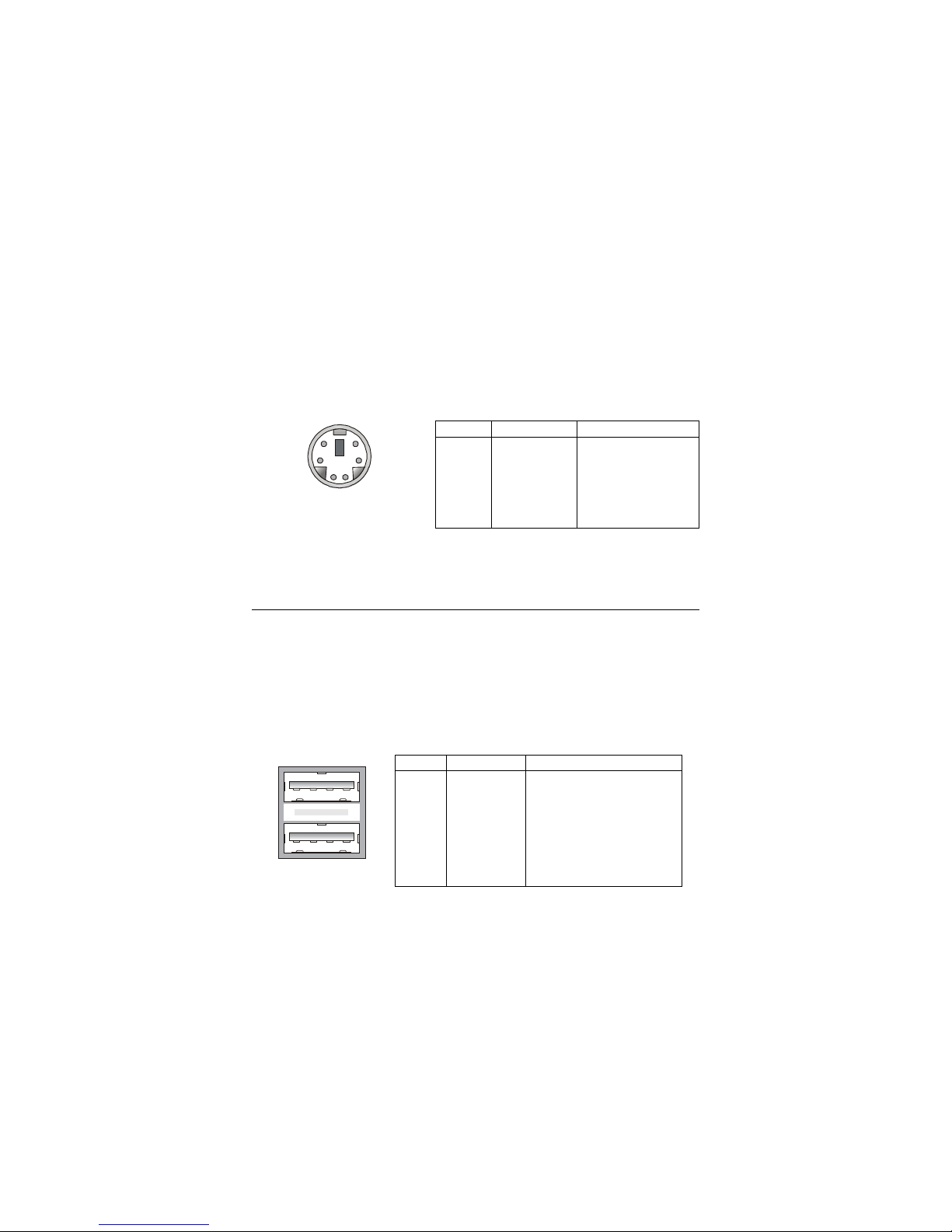
USB Connectors
The mainboard provides a UHCI (Universal Host Controller Interface)
Universal Serial Bus root for attaching USB devices such as keyboard, mouse
or other USB-compatible devices. You can plug the USB device directly into
ths connector.
USB Ports
1 2 3 4
5 6 7 8
PIN SIGNAL DESCRIPTION
1 VCC +5V
2 -Data 0 Negative Data Channel 0
3 +Data0 Positive Data Channel 0
4 GND Ground
5 VCC +5V
6 -Data 1 Negative Data Channel 1
7 +Data 1 Positive Data Channel 1
8 GND Ground
USB Port Description
PIN SIGNAL DESCRIPTION
1 Keyboard DATA Keyboard DAT A
2 NC No connection
3 GND Ground
4 VCC +5V
5 Keyboard Clock Keyboard clock
6 NC No connection
Pin Definition
PS/2 Keyboard (6-pin Female)
2
1
3
4
5
6
Chapter 2
2-10
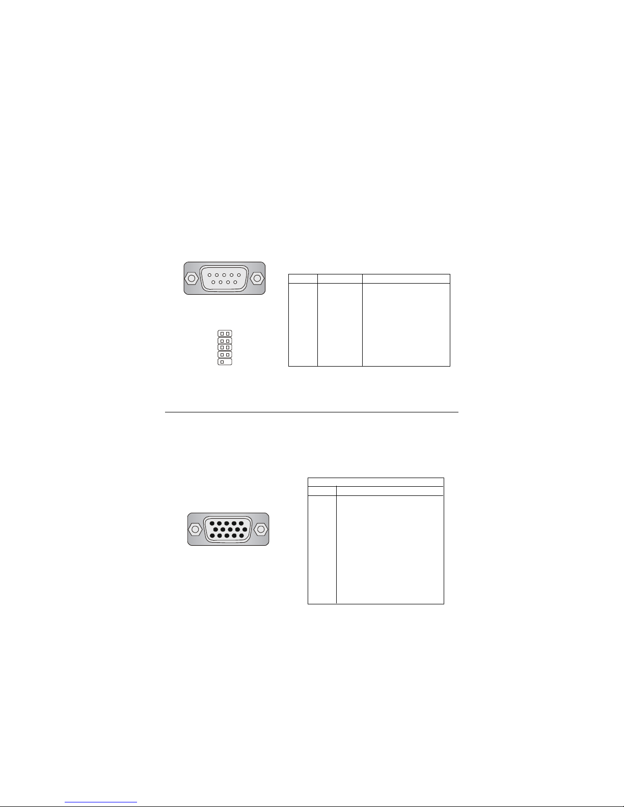
9-Pin Serial Port Connector
1 2 3 4 5
6 7 8 9
Serial Port Connector: COM A & COM 2
One 9-pin male DIN serial port COM A and one 9-pin COM2 pin header
are supplied. You can attach a serial mouse or other serial devices to the
connectors.
VGA DB 15 Pin Connector
One DB 15-pin VGA connector is provided for connection to a VGA
monitor.
DB 15-Pin Female Connector
5 1
15 11
Analog Video Display Connector (DB-15S)
PIN SIGNAL DESCRIPTION
1 Red
2 Green
3 Blue
4 Not used
5 Ground
6 Ground
7 Ground
8 Ground
9 Power
10 Ground
1 1 Not used
12 SDA
13 Horizontal Sync
14 Vertical Sync
15 SCL
Pin Definition
2
10
1
9
PIN SIGNAL DESCRIPTION
1 DCD Data Carry Detect
2 SIN Serial In or Receive Data
3 SOUT Serial Out or Transmit Data
4 DTR Data Terminal Ready
5 GND Ground
6 DSR Data Set Ready
7 RTS Request To Send
8 CTS Clear To Send
9 RI Ring Indicate
Pin Definition
Hardware Setup
2-11
Joystick/Midi Connectors
You can connect a joystick or game pad to this connector.
Audio Port Connectors
Line Out is a connector for Speakers or Headphones. Line In is used for
external CD player, Tape player, or other audio devices. Mic is a connector for
microphones.
1/8” Stereo Audio Connectors
Line Out Line In M IC
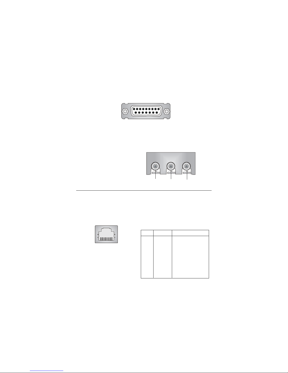
RJ-45 LAN Jack (Optional)
The mainboard provides one standard RJ-45 jack for connection to Local
Area Network (LAN). Y ou can connect a network cable to the LAN jack.
Pin Definition
PIN SIGNAL DESCRIPTION
1 TDP Transmit Differential Pair
2 TDN Transmit Differential Pair
3 RDP Receive Differential Pair
4 NC Not Used
5 NC Not Used
6 RDN Receive Differential Pair
7 NC Not Used
8 NC Not Used
RJ-45 LAN Jack
Chapter 2
2-12
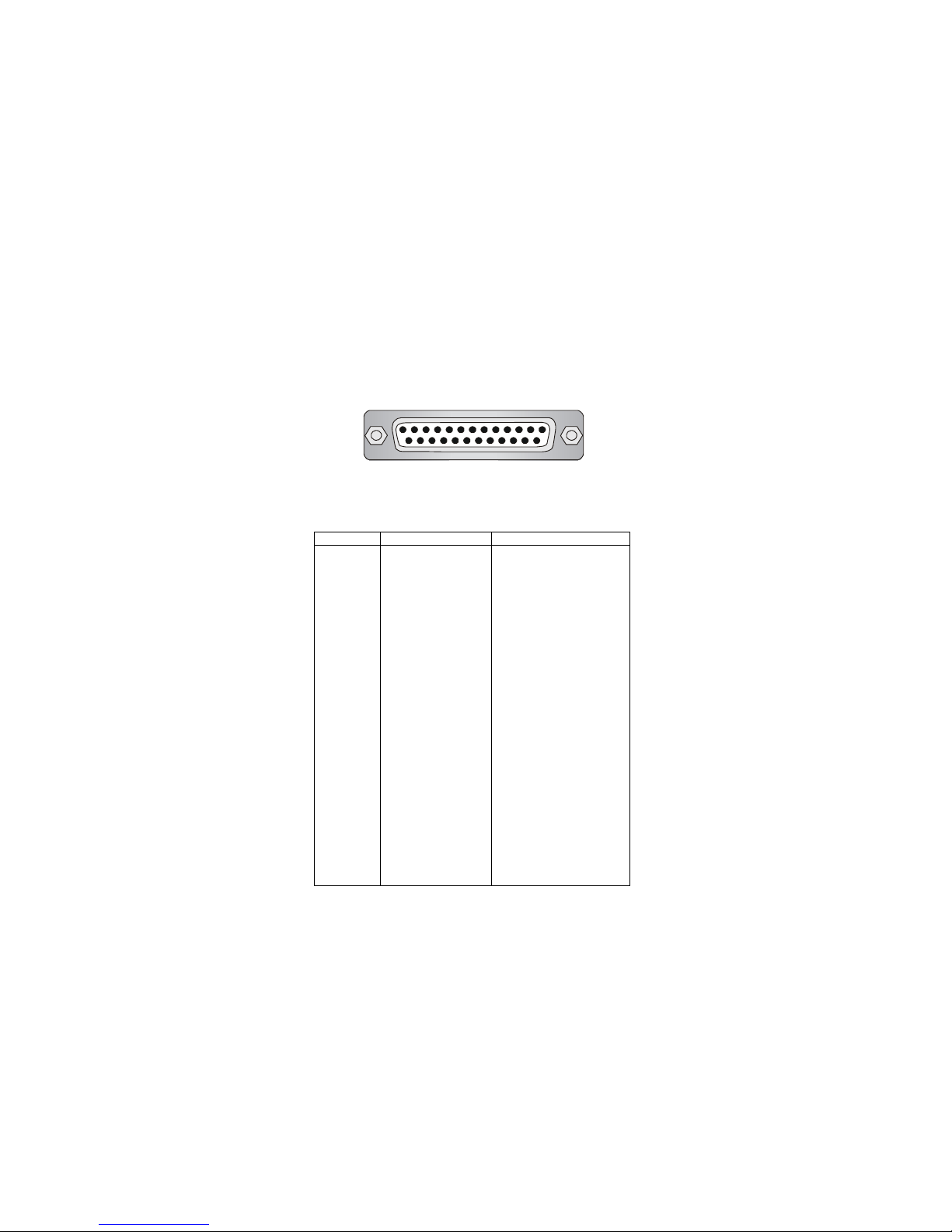
Parallel Port Connector: LPT1
The mainboard provides a 25-pin female centronic connector as LPT. A
parallel port is a standard printer port that supports Enhanced Parallel Port
(EPP) and Extended Capabilities Parallel Port (ECP) mode.
13 1
14
25
PIN SIGNAL DESCRIPTION
1 STROBE Strobe
2 DATA0 Data0
3 DATA1 Data1
4 DATA2 Data2
5 DATA3 Data3
6 DATA4 Data4
7 DATA5 Data5
8 DATA6 Data6
9 DATA7 Data7
10 ACK# Acknowledge
11 BUSY Busy
12 P E Paper End
13 SELECT Select
14 AUTO FEED# Automatic Feed
15 ERR# Error
16 INIT# Initialize Printer
17 SLIN# Select In
18 GND Ground
19 GND Ground
20 GND Ground
21 GND Ground
22 GND Ground
23 GND Ground
24 GND Ground
25 GND Ground
Pin Definition
Hardware Setup
2-13
The mainboard provides connectors to connect to FDD, IDE HDD, case,
modem, LAN, USB Ports, IR module and CPU/System F AN.
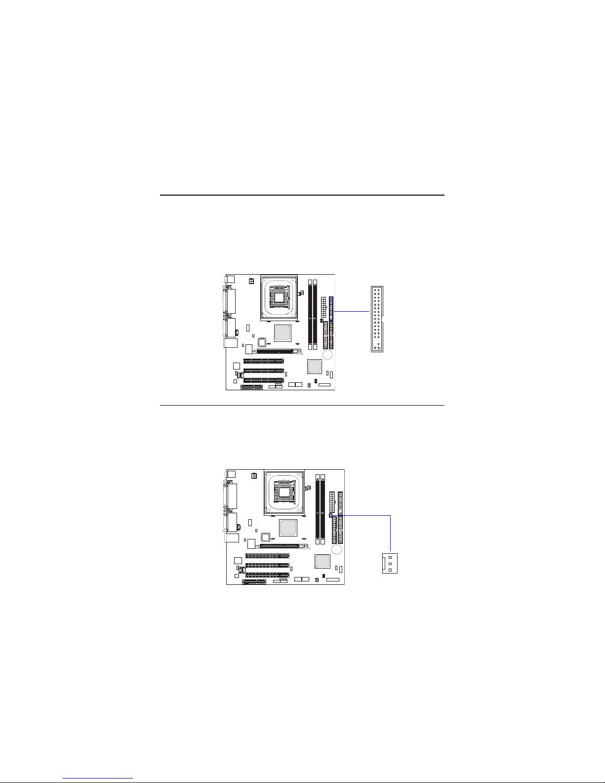
Floppy Disk Drive Connector: FDD1
The mainboard provides a standard floppy disk drive connector that
supports 360K, 720K, 1.2M, 1.44M and 2.88M floppy disk types.
Connectors
FDD1
Independent Power Switch Connector: PWRSW1 (Optional)
The connector is connected to an independent power switch on the
case. Touch the power switch’s touch pad will turn on/off the computer .
PWRSW1
GND
+5VSB
PS-ON
1
 Loading...