

MSI MS-6551 User Manual
i
Version 1.0
G52-MA00484
MS-6551(v1.X) ATX Mainboard
MSI
MICRO-STAR INTERNATIONAL
ii
Manual Rev: 1.0
Release Date: Nov. 2001
FCC-B Radio Frequency Interference Statement
This equipment has been tested and found to comply with the limits for a class
B digital device, pursuant to part 15 of the FCC rules. These limits are designed
to provide reasonable protection against harmful interference when the equipment is operated in a commercial environment. This equipment generates, uses
and can radiate radio frequency energy and, if not installed and used in accordance with the instruction manual, may cause harmful interference to radio
communications. Operation of this equipment in a residential area is likely to
cause harmful interference, in which case the user will be required to correct
the interference at his own expense.
Notice 1
The changes or modifications not expressly approved by the party responsible for compliance could void the user’s authority to operate the equipment.
Notice 2
Shielded interface cables and A.C. power cord, if any, must be used in order to
comply with the emission limits.
VOIR LA NOTICE D’INSTALLATION AVANT DE RACCORDER AU
RESEAU.
Micro-Star International MS-6551
Tested to comply
with FCC Standard
For Home or Office Use

iii
Edition
Nov 2001
Copyright Notice
The material in this document is the intellectual property of MICROSTAR INTERNATIONAL. We take every care in the preparation
of this document, but no guarantee is given as to the correctness of its
contents. Our products are under continual improvement and we reserve the right to make changes without notice.
Trademarks
All trademarks used in this manual are the property of their respective
owners.
Intel and Pentium are registered trademarks of Intel Corporation.
PS/2 and OS/2 are registered trademarks of IBM Corporation.
Windows 95/98/2000 and Windows NT are registered trademarks of Microsoft.
Netware is a registered trademark of Novell.
Award is a registered trademark of Award Software Inc.
Revision History
Revision Revision History Date
V1.0 First release for PCB 1.X Nov. 2001

iv
1. Always read the safety instructions carefully.
2. Keep this User’s Manual for future reference.
3. Keep this equipment away from humidity.
4. Lay this equipment on a reliable flat surface before setting it up.
5. The openings on the enclosure are for air convection hence protects the
equipment from overheating. DO NOT COVER THE OPENINGS.
6. Make sure the voltage of the power source and adjust properly 110/220V
before connecting the equipment to the power inlet.
7. Place the power cord such a way that people can not step on it. Do not
place anything over the power cord.
8. Always Unplug the Power Cord before inserting any add-on card or module.
9. All cautions and warnings on the equipment should be noted.
10. Never pour any liquid into the opening that could damage or cause electrical shock.
11. If any of the following situations arises, get the equipment checked by a
service personnel:
z The power cord or plug is damaged
z Liquid has penetrated into the equipment
z The equipment has been exposed to moisture
z The equipment has not work well or you can not get it work according
to User’s Manual.
z The equipment has dropped and damaged
z If the equipment has obvious sign of breakage
12. DO NOT LEAVE THIS EQUIPMENT IN AN ENVIRONMENT
UNCONDITIONED, STORAGE TEMPERATURE ABOVE 600 C (1400F), IT
MAY DAMAGE THE EQUIPMENT.
Safety Instructions
CAUTION: Danger of explosion if battery is incorrectly replaced.
Replace only with the same or equivalent type recommended by the
manufacturer.

v
CONTENTS
Chapter 1. Getting Started ........................................................................ 1-1
Mainboard Specification ......................................................................1-3
Mainboard Layout ...............................................................................1-5
Quick Components Guide ....................................................................1-5
Chapter 2. Hardware Setup ....................................................................... 2-1
Central Processing Unit: CPU ..............................................................2-2
CPU Installation Procedures .........................................................2-2
Installing the CPU Fan ..................................................................2-3
CPU Core Speed Derivation Procedure .........................................2-4
Memory................................................................................................2-5
Introduction to DDR SDRAM.......................................................2-5
DDR Module Combination ............................................................ 2-6
DDR Module Installation Procedure ............................................. 2-6
Power Supply ....................................................................................... 2-7
ATX 20-Pin Power Supply ............................................................. 2-7
ATX 12V Power Connector: JPW1 ................................................2-7
Back Panel ............................................................................................2-8
Mouse Connector ......................................................................... 2-8
Keyboard Connector ..................................................................... 2-9
USB Connectors ............................................................................ 2-9
Serial Port Connectors: COM A & COM B..................................2-10
Joystick/Midi Connectors ........................................................... 2-10
Audio Port Connectors ............................................................... 2-10
Parallel Port Connector ................................................................ 2-11
LAN Jack (RJ-45) ......................................................................... 2-12
Connectors......................................................................................... 2-13
Floppy Disk Drive Connector: FDD1...........................................2-13
CD-IN1/MDM_IN1/AUX_IN1 Connectors................................. 2-13
Hard Disk Connectors: IDE1 & IDE2 ........................................... 2-14

vi
Fan Power Connectors: CPU_F AN/CHS_FAN/BAK_FAN ......... 2-15
Wake On Ring Connector: JMDM1 ............................................. 2-16
Wake On LAN Connector: JWOL1.............................................. 2-16
Power Saving Switch Connector: JGS1........................................2-17
Power Saving LED Connector: JGLED1....................................... 2-17
Front Panel Connector: F_P1.......................................................2-18
Front Panel Audio Connector: JAUDIO1 .................................... 2-20
Front USB Connectors: USB1 ..................................................... 2-21
IrDA Infrared Module Header: IR1 .............................................. 2-22
Jumpers .............................................................................................. 2-23
Clear CMOS Jumper: JBA T1........................................................ 2-23
BIOS Flush Jumper: J3 ................................................................. 2-24
Onboard Audio Jumper: JP2........................................................ 2-24
Slots ................................................................................................... 2-25
AGP (Accelerated Graphics Port) Slot......................................... 2-25
PCI Slots...................................................................................... 2-25
CNR (Communication Network Riser) ......................................... 2-26
PCI Interrupt Request Routing .................................................... 2-26
Chapter 3. BIOS Setup.............................................................................. 3-1
Entering Setup......................................................................................3-2
Control Keys ................................................................................. 3 -2
Getting Help .................................................................................. 3-3
The Main Menu ...................................................................................3-4
Standard CMOS Features ....................................................................3-6
Advanced BIOS Features ....................................................................3-8
Advanced Chipset Features...............................................................3-11
Integrated Peripherals ........................................................................ 3-13
Power Management Setup ................................................................. 3-17
PNP/PCI Configurations..................................................................... 3-21

vii
PC Health Status ................................................................................ 3-23
Frequency/Voltage Control ................................................................ 3-24
Load Fail-Safe/Optimized Defaults ..................................................... 3-26
Supervisor/User Password................................................................. 3-28

Getting Started
1-1
Chapter 1. Getting Started
1
Getting Started
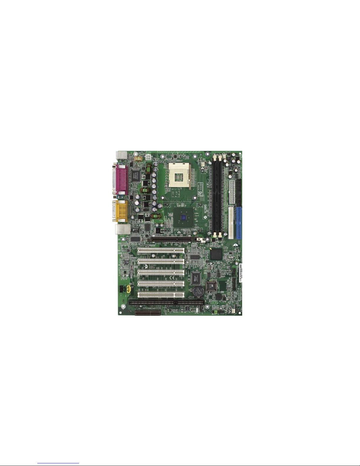
Thank you for purchasing the MS-6551 v1.0 ATX mainboard. The MS6551 v1.0 is based on Intel® Brookdale & ICH2 chipsets for optimal system
performance. Designed to fit the advanced Intel® Pentium® 4 processors in the
478 pin package, the MS-6551 v1.0 provides you with an ideal and professional
desktop platform solution.
TOPICS
Mainboard Specification 1-2
Mainboard Layout 1-4
Quick Components Guide 1-5

Chapter 1
1-2
CPU
Support Socket478 for Intel® Pentium 4 processor
Support 1.3GHz, 1.4GHz and up to 2.XGHz
Chipset
Intel® Brookdale chipset
- AGP 4x universal slot
- Support 100MHz FSB
- Support 400MHz Intel NetBurst micro-architecture bus.
Intel® ICH2 chipset. (360 BGA)
- AC’97 Controller Integrated
- 2 full IDE channels, up to ATA100
- Integrated 10/100Mbit/sec Ethernet
- Low pin count interface for Winbond SIO
Main Memory
Support two 184-pin DDRs.
Max. memory size at 2GB.
Slots
One CNR(Communication Network Riser).
One AGP(Accelerated Graphics Port) 4x slot.
Five PCI 2.2 32-bit Master PCI Bus slots.
Support 3.3v/5v PCI bus Interface.
One ISA slot (optional)
On-Board IDE
An IDE controller on the ICH2 chipset provides IDE HDD/CD-ROM with
PIO, Bus Master and Ultra DMA66/100 operation modes.
Can connect up to four IDE devices
Mainboard Specification
Note: The AGP slot DOES NOT support 3.3V AGP card. Use of
3.3V AGP card may cause damage to the mainboard.

Getting Started
1-3
On-Board Peripherals
On-Board Peripherals include:
- 1 floppy port supports 2 FDD with 360K, 720K, 1.2M,
1.44M and 2.88Mbytes.
- 2 serial ports (COMA & COMB)
- 1 parallel port supports SPP/EPP/ECP mode
- 4 USB ports (Rear * 2 / Front * 2)
- 1 RJ45 Connector (optional)
- 1 Line-In/Line-Out/Mic-In/Game port
Network
ICH2 Integrated LAN Controller
Intel 82562 ET/EM (optional)
Audio
ICH2 chip integrated
AC97 2.1 Compliant.
Support 2 Channel Audio
BIOS
The mainboard BIOS provides “Plug & Play” BIOS which detects the
peripheral devices and expansion cards of the board automatically.
The mainboard provides a Desktop Management Interface(DMI) function
which records your mainboard specifications.
Dimension
ATX Form Factor (9.6” x 9.05”)
Mounting
6 mounting holes.
Chapter 1
1-4
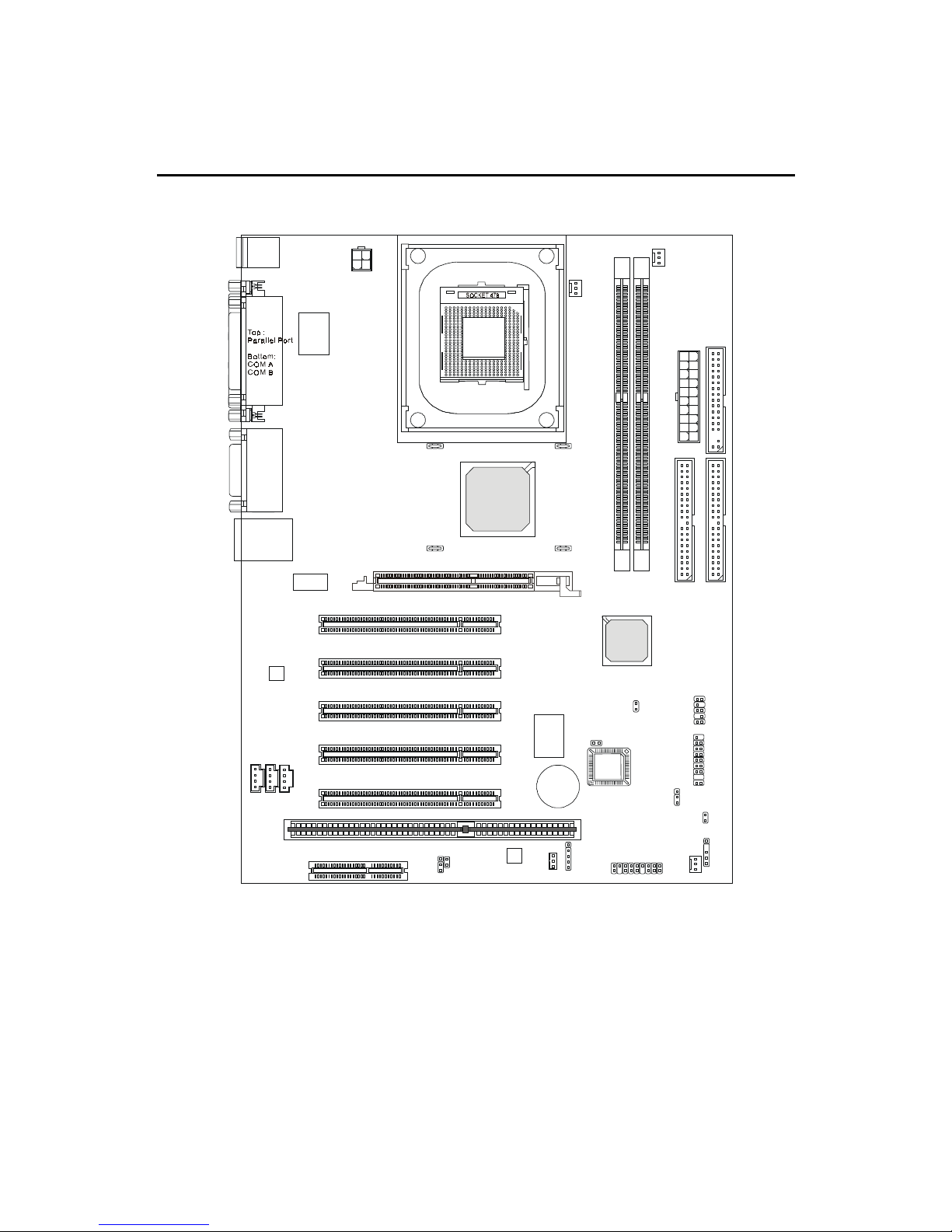
Mainboard Layout
MS-6551 v1.X ATX Mainboard
D
D
R
1
D
D
R
2
JWOL1
JP2
J5
Winbond
W83629D
JMDM1
A
T
X
P
o
w
e
r
S
u
p
p
l
y
F_P1
JBAT1
JGLED1
IR1
JAUDIO1
CHS_FAN
USB1
PCI Slot 3
PCI Slot 1
PCI Slot 4
PCI Slot 2
PCI Slot 5
I
D
E
1
I
D
E
2
CNR
ISA Slot
J3
JGS1
Top : m ous e
Bottom: keyboard
Top :
LAN Jack
Bottom:
USB ports
Top :
Game port
Bottom:
Line-Out
Line-In
Mic
F
D
D
1
Codec
W
i
n
b
o
n
d
W
8
3
6
2
7
H
F
-
A
W
Winbond
W83628F
JPW1
Intel Lan
CD_IN1
AUX_IN1
MDM_IN1
C_FAN1
CPU_FAN
P_FAN1
BAK_FAN
AGP Slot
BATT
+
ICH2
Intel
Brookdale
chipset
FWH

Getting Started
1-5
Quick Components Guide
Component Function Reference
Socket 478 Installing CPU See p. 2-2
DDR1 & DDR 2 Installing DDR Memory See p. 2-5
ATX Power Supply Connect to ATX power supply See p. 2-7
JPW1 Connect to ATX 12V power See p. 2-7
Mouse Connector Connect to PS/2 mouse See p. 2-8
Keyboard Connector Connect to PS/2 keyboard See p. 2-9
COM A & COM B Connec to serial devices See p. 2-10
Joystick/Midi Connectors Connect to joeystick/game pad See p. 2-10
Parallel Port Connect to printer See p. 2-11
LAN Jack Connect to LAN See p. 2-12
FDD1 Connect to FDD See p. 2-13
CD_IN1 CD-in connector See p. 2-13
IDE1& IDE2 Connect to HDD See p. 2-14
CPU-FAN/BAK-FAN Fan power connectors See p. 2-15
CHS-FAN
JMDM1 Wake on ring connector See p. 2-16
JWOL1 Wake on LAN connector See p. 2-16
JGS1 Power saving switch connector See p. 2-17
JGLED1 Power saving LED connector See p. 2-17
F_P1 Front panel connector See p. 2-18
JAUDIO1 Front panel audio connector See p. 2-20
USB1 Front USB connector See p. 2-21
IR1 IrDA infrared module connector See p. 2-22
JBAT1 Clear CMOS jumper See p. 2-23
J3 BIOS flash jumper See p. 2-24
JP2 Enable onboard audio device See p. 2-24
AGP Connecting to AGP cards See p. 2-25
PCI Slots Connecting to expansion cards See p. 2-25
CNR Slot Connecting to expansion cards See p. 2-26
ISA Slot Connect to ISA expansion card See p. 2-26

Hardware Setup
2-1
Chapter 2. Hardware Setup
TOPICS
Central Processing Unit: CPU 2-2
Memory 2-5
Power Supply 2-7
Back Panel 2-8
Connectors 2-12
Jumpers 2-23
Slots 2-25
2
Hardware Setup
This chapter provides you with the information about hardware setup
procedures. While doing the installation, be careful in holding the components
and follow the installation procedures. For some components, if you install in
the wrong orientation, the components will not work properly.
Use a grounded wrist strap before handling computer components. Static
electricity may damage the components.
Chapter 2
2-2
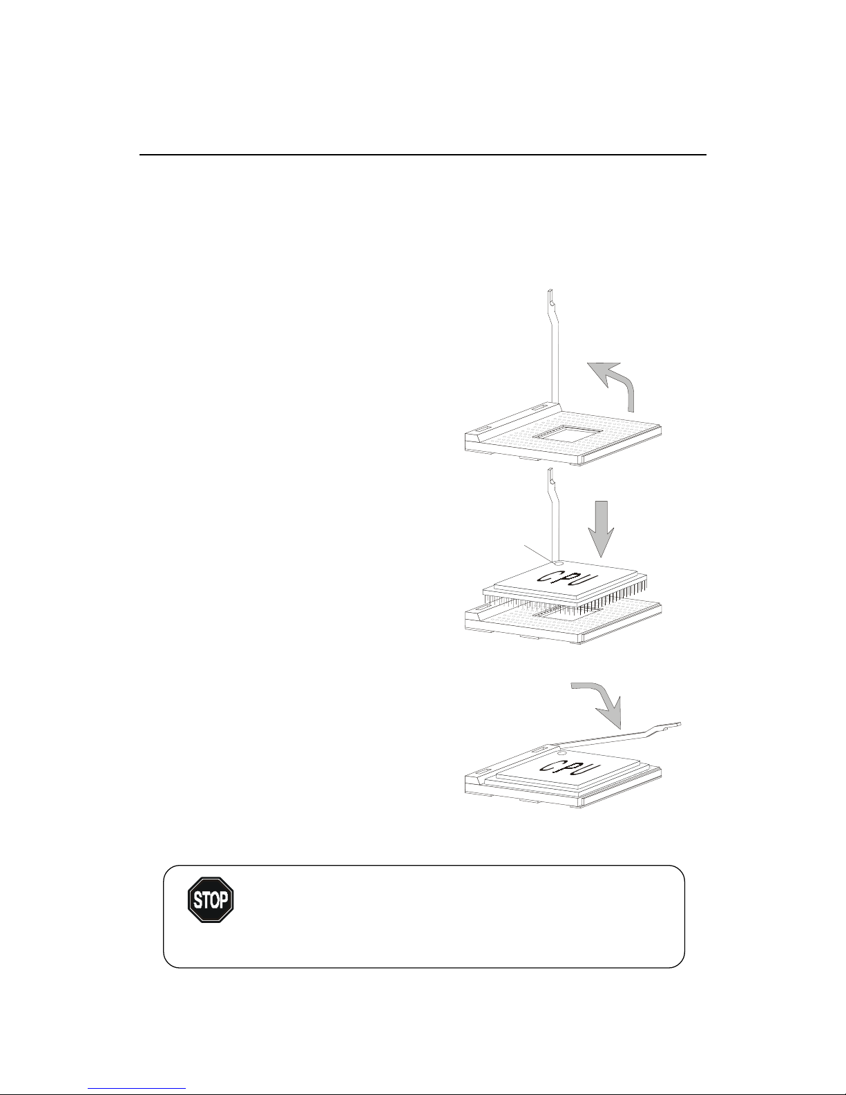
Central Processing Unit: CPU
1. Pull the lever sideways away
from the socket. Then, raise
the lever up to a 90-degree
angle.
2 . Look for the dot/cut edge. The
dot/cut edge should point towards the lever pivot. The
CPU will only fit in the correct
orientation.
3. Hold the CPU down firmly,
and then close the lever to
complete the installation.
CPU Installation Procedures
Open Lever
Dot / Cut edge
Sliding
Plate
Close
Lever
The mainboard supports Intel® Pentium® 4 processor in the 478 pin
package. The mainboard uses a CPU socket called PGA478 for easy CPU
installation. When you are installing the CPU, make sure the CPU has a heat
sink and a cooling fan attached on the top to prevent overheating. If you do not
find the heat sink and cooling fan, contact your dealer to purchase and install
them before turning on the computer.
Overheating will seriously damage the CPU and system,
always make sure the cooling fan can work properly to
protect the CPU from overheating.
WARNING!
Hardware Setup
2-3
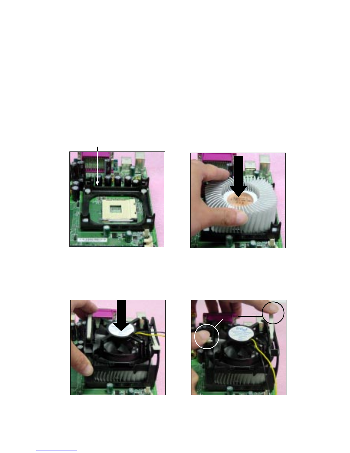
Installing the CPU Fan
As processor technology pushes to faster speeds and higher
performance, thermal management becomes increasingly important. To dissipate heat, you need to attach the CPU cooling fan and heatsink on top of the
CPU. Follow the instructions below to install the Heatsink/Fan:
2. Position the heatsink onto the reten-
tion mechanism.
1. Locate the CPU and its retention
mechanism on the motherboard.
3. Mount the fan on top of the heatsink.
Press down the fan until its four clips
get wedged in the holes of the retention mechanism.
4. Press the two levers down to fasten
the fan. Each lever can be pressed
down in only ONE direction.
retention mechanism
levers
Chapter 2
2-4
CPU Core Speed Derivation Procedure
If CPU Clock = 100MHz
Core/Bus ratio = 14
then CPU core speed = Host Clock x Core/Bus ratio
= 100MHz x 14
= 1.4GHz
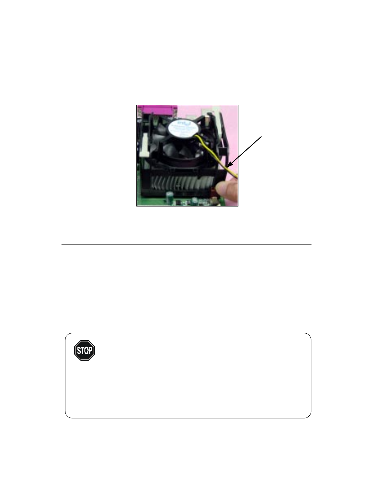
5. Connect the fan power cable from the mounted fan to the 3-pin fan power connector
on the board.
fan power cable
Overclocking
This motherboard is designed to support overclocking.
However, please make sure your components are able to
tolerate such abnormal setting, while doing overclocking.
Any attempt to operate beyond product specifications is not
recommended. We do not guarantee the damages or risks
caused by inadequate operation or beyond product
specifications.
W ARNING!
Hardware Setup
2-5
Memory
Introduction to DDR SDRAM
DDR (Double Data Rate) SDRAM is similar to conventional SDRAM,
but doubles the rate by transferring data twice per cycle. It uses 2.5 volts as
opposed to 3.3 volts used in SDR SDRAM, and requires 184-pin DIMM modules rather than 168-pin DIMM modules used by SDR SDRAM. T wo types of
DDR are available at the time of writing: PC1600 & PC2100. PC1600 DDR SDRAM
running at 100MHz will produce about 1.6GB/s memory bandwidth. PC2100
running at 133MHz will produce 2.1GB/s memory bandwidth. High memory
bandwidth makes DDR an ideal solution for high performance PC, workstations and servers.
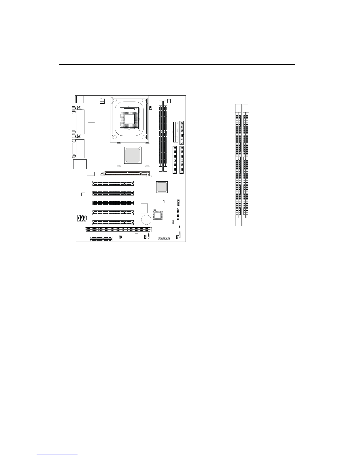
The mainboard provides two 184-pin DDR DIMM slots and supports a
total memory size up to 2 GB.
DDR1 DDR2
Chapter 2
2-6
DDR Module Combination
You can install either single sided or double sided DDR SDRAM mod-
ules into the DDR DIMM slots (DDR 1~2) in any combination as follows:
Socket Memory Module Total Memory
DIMM 1 64MB, 128MB,
64MB ~ 512MB
256MB, 512MB
DIMM 2 64MB, 128MB,
64MB ~ 512MB
256MB, 512MB
Maximum System Memory Supported 64MB ~ 2GB
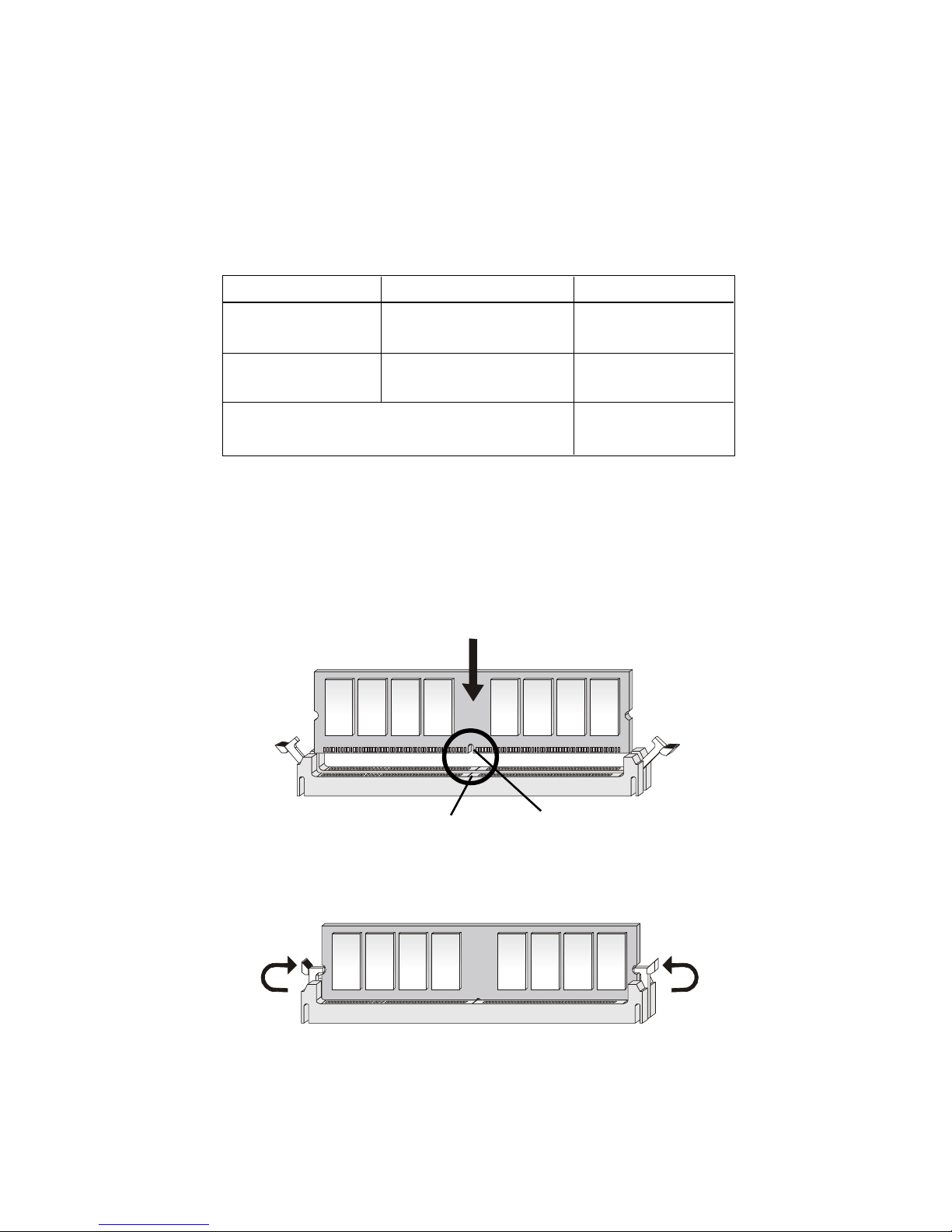
DDR Module Installation Procedure
1. The DDR DIMM has only one notch on the center of module.
The module will only fit in the right orientation.
2. Insert the DIMM memory module vertically into the DIMM slot.
Then push it in.
Volt
notch
3. The plastic clip at each side of the DIMM slot will automatically
close.
Hardware Setup
2-7
Power Supply
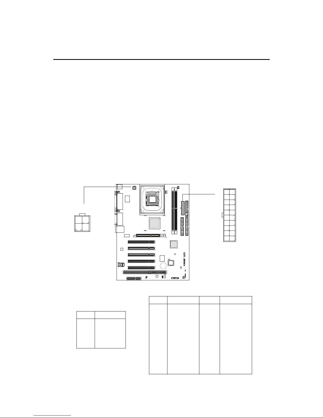
A TX 20-Pin Power Supply
This connector allows you to connect to an ATX power supply. To
connect to the ATX power supply , make sure the plugs of the power supply is
inserted in the proper orientation and the pins are aligned. Then push down
the power supply firmly into the connector. The power connector supports
instant power on function which means that system will boot up immediately
when the power supply connector is inserted on the board.
The mainboard supports ATX power supply for the power system. Before inserting the power supply connector, always make sure that all components are installed properly to ensure that no damage will be caused.
A TX 12V Power Connector: JPW1
This 12V power connector is used to provide power to the CPU.
JPW1
1
3
2
4
ATX Power Supply
10
1
20
11
PIN SIGNAL
1 GND
2 GND
3 12V
4 12V
JPW1 Pin Definition
PIN SIGNAL
11 3.3V
12 -12V
13 GND
14 PS_ON
15 GND
16 GND
17 GND
1 8 -5V
19 5V
20 5V
PIN SIGNAL
1 3.3V
2 3.3V
3 GND
45V
5 GND
65V
7 GND
8 PW_OK
9 5V_SB
10 12V
ATX Power Supply Pin Definition
Chapter 2
2-8
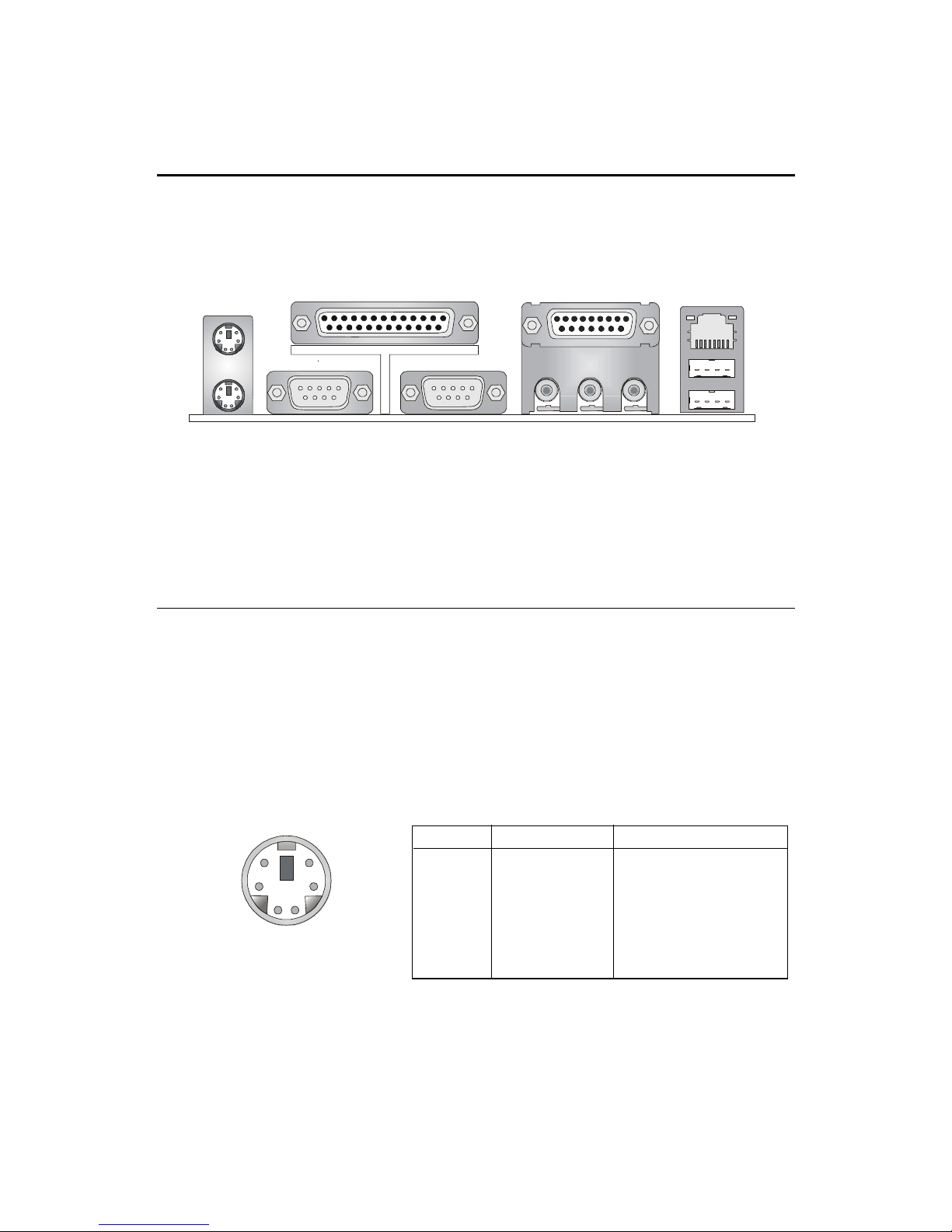
The Back Panel provides the following connectors:
Back Panel
Mouse Connector
The mainboard provides a standard PS/2® mouse mini DIN connector for
attaching a PS/2® mouse. You can plug a PS/2® mouse directly into this
connector. The connector location and pin assignments are as follows:
PS/2 Mouse (6-pin Female)
Mouse
Keyboard
Parallel
COM A
COM B
L-out
L-in MIC
Midi/Joystick
PIN SIGNAL DESCRIPTION
1 Mouse DATA Mouse DAT A
2 NC No connection
3 GND Ground
4 VCC +5V
5 Mouse Clock Mouse clock
6 NC No connection
Pin Definition
USB
LAN
2
1
3
4
56
Hardware Setup
2-9
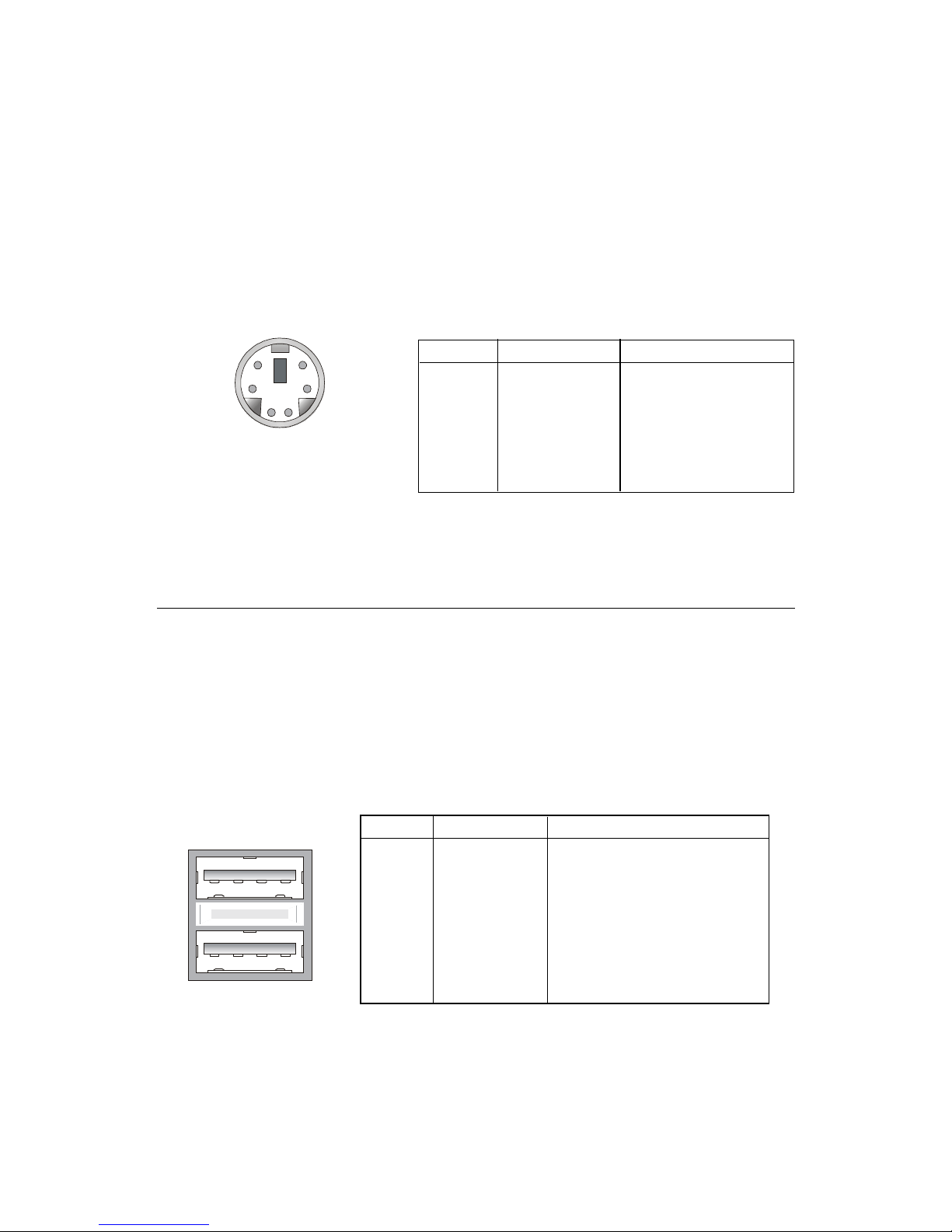
Keyboard Connector
The mainboard provides a standard PS/2® keyboard mini DIN connector
for attaching a PS/2® keyboard. You can plug a PS/2® keyboard directly into
this connector.
PS/2 Keyboard (6-pin Female)
USB Connectors
The mainboard provides a UHCI (Universal Host Controller Interface)
Universal Serial Bus root for attaching USB devices such as keyboard, mouse
or other USB-compatible devices. You can plug the USB device directly into
this connector.
USB Ports
1 2 3 4
5 6 7 8
PIN SIGNAL DESCRIPTION
1 VCC +5V
2 -Data 0 Negative Data Channel 0
3 +Data0 Positive Data Channel 0
4 GND Ground
5 VCC +5V
6 -Data 1 Negative Data Channel 1
7 +Data 1 Positive Data Channel 1
8 GND Ground
USB Port Description
PIN SIGNAL DESCRIPTION
1 Keyboard DAT A Keyboard DA T A
2 NC No connection
3 GND Ground
4 VCC +5V
5 Keyboard Clock Keyboard clock
6 NC No connection
Pin Definition
2
1
3
4
56
 Loading...