

MSI 915, Midas 915, MS-6275 User Manual

Midas 915
User’s Guide
G52-B6275X1

FCC-B Radio Frequency Interference Statement
This equipment has been tested and found to comply with the limits for
a class B digital device, pursuant to part 15 of the FCC rules. These limits
are designed to provide reasonable protection against harmful interference when the equipment is operated in a commercial environment. This
equipment generates, uses and can radiate radio frequency energy and, if
not installed and used in accordance with the instruction manual, may
cause harmful interference to radio communications. Operation of this
equipment in a residential area is likely to cause harmful interference, in
which case the user will be required to correct the interference at his own
expense.
Notice 1
The changes or modifications not expressly approved by the party responsible for compliance could void the user’s authority to operate the
equipment.
Notice 2
Shielded interface cables and AC. power cord, if any, must be used in
This device complies with Part 15 of the FCC Rules. Operation is
subject to the following two conditions:
(1) this device may not cause harmful interference, and
(2) this device must accept any interference received, including
interference that may cause undesired operation.
Micro-Star International
Midas 915
ii

Trademarks
All trademarks are the properties of their respective owners.
Intel® and Pentium® are registered trademarks of Intel Corporation.
PS/2 and OS®/2 are registered trademarks of International Business Machines Corporation.
Windows® 95/98/2000/NT/XP are registered trademarks of Microsoft
Corporation.
Netware® is a registered trademark of Novell, Inc.
Award® is a registered trademark of Phoenix Technologies Ltd.
AMI® is a registered trademark of American Megatrends Inc.
Revision History
Revision Revision History Date
V1.0 First Release March 2005
Copyright Notice
The material in this document is the intellectual property of MICROSTAR INTERNATIONAL. We take every care in the preparation of this
document, but no guarantee is given as to the correctness of its contents.
Our products are under continual improvement and we reserve the right
to make changes without notice.
iii

Safety Instructions
1. Always read the safety instructions carefully.
2. Keep this User’s Manual for future reference.
3. Keep this equipment away from humidity.
4. Lay this equipment on a reliable flat surface before setting it up.
5. The openings on the enclosure are for air convection hence pro
tects the equipment from overheating. DO NOT COVER THE
OPENINGS.
6. Make sure the voltage of the power source and adjust properly
115/230V before connecting the equipment to the power inlet.
7. Place the power cord such a way that people can not step on it.
Do not place anything over the power cord.
8. Always Unplug the Power Cord before inserting any add-on card
or module.
9. All cautions and warnings on the equipment should be noted.
10. Never pour any liquid into the opening that could damage or cause electrical shock.
11. If any of the following situations arises, get the equipment checked
by a service personnel:
- The power cord or plug is damaged.
- Liquid has penetrated into the equipment.
- The equipment has been exposed to moisture.
- The equipment has not work well or you can not get it work according
to User’s Manual.
- The equipment has dropped and damaged.
- The equipment has obvious sign of breakage.
12. Do not leave this equipment in an unconditioned environment with
storage temperature above 600 C (1400F). Extreme heat may damage the equipment.
CAUTION: Danger of explosion if battery is incorrectly replaced.
Replace only with the same or equivalent type recommended by the
manufacturer.
iv

CONTENTS
Chapter 1. Getting Started........................................................................1-1
1.1 System Specifications...................................................1-2
1.2 System Configuration...................................................1-4
1.3 Thermal Solution..........................................................1-7
Chapter 2. Introducing Mainboard..........................................................2-1
2.1 Mainboard Layout...................................................................2-2
2.2 CPU.............................................................................2-3
CPU & Cooler Installation...........................................2-3
2.3 Memory.......................................................................2-7
Introduction to DDR SDRAM.............................................2-7
DDR Module Combination..................................................2-8
Installing DDR Modules......................................................2-8
2.4 Power Supply...............................................................2-9
ATX 24-Pin Power Connector: ATX............................2-9
ATX 12V Power Connector: ATX_12V........................2-9
2.5 Front Panel.................................................................2-10
Audio Ports...........................................................................2-10
USB Ports.............................................................................2-10
2.6 Rear Panel..................................................................2-11
Mouse/Keyboard Connectors.................................2-11
Audio Ports.............................................................2-12
VGA Port.................................................................2-12
RJ-45 LAN Jack........................................................2-13
USB Ports...............................................................2-13
Parallel Port..............................................................2-14
Serial Port................................................................2-15
2.7 Connectors.............................................................................2-16
IDE Connector: IDE1...........................................................2-16
v

Floppy Disk Drive Connector: FDD..................................2-16
Serial ATA Connectors: SATA1~ SATA4 ........................2-17
Front Panel Audio Connector: F_AUDIO........................2-17
Front Panel Connector: JFP1..............................................2-18
CD-in Connector: CD_IN......................................................2-18
Fan Power Connectors: CPU_FAN/SYS_FAN.................2-19
Serial Port Connector: JCOM2............................................2-19
Front USB Connectors: F_USB1/F_USB2........................2-20
2.8 Jumper.......................................................................2-21
BIOS Flash Jumper: BIOS_WP..................................2-21
Clear CMOS Jumper: CLR_CMOS...................................2-21
2.9 Slot............................................................................2-22
PCI (Peripheral Component Interconnect) Slots.............2-22
PCI Interrupt Request Routing..........................................2-22
PCI Express Slot..................................................................2-23
Chapter 3. System Assembly........................................................3-1
3.1 Overview......................................................................3-2
Installation Tools.......................................................3-2
Screws.......................................................................3-2
Checking the Items.....................................................3-3
3.2 Installation Procedures.................................................3-4
1. Removing Cover, Installing Memory Modules.........3-4
2. Installing CPU.........................................................3-5
3. Installing CPU Cooler..............................................3-6
4. Removing Drive Cage.............................................3-7
5. Installing HDD........................................................3-8
6. Installing FDD and Optical Drive.............................3-9
7. Restoring Chassis Cover.......................................3-11
Chapter 4. BIOS Setup.................................................................4-1
Entering Setup..............................................................................4-2
vi

Control Keys.........................................................................4-2
Getting Help...........................................................................4-3
The Main Menu.............................................................................4-4
Standard CMOS Features...........................................................4-6
Advanced BIOS Features...........................................................4-8
Advanced Chipset Features.....................................................4-11
Integrated Peripherals................................................................4-14
Power Management Setup........................................................4-19
PNP/PCI Configurations............................................................4-21
H/W Monitor................................................................................4-22
Frequency/Voltage Control.......................................................4-23
Load Fail-Safe/Optimized Defaults..........................................4-24
Set Password...............................................................................4-25
vii

Getting Started
Congratulations for purchasing Midas 915 (MS-6275)
barebone. Midas barebone is your best Slim PC choice. Based on
the “all-in-one” design idea, Midas provides 6 USB ports, 3 PCI
slots for expansion and 1 PCI-E slot (low profile). With the fantas-
tic appearance and small form factor, it can easily be set anywhere.
The feature packed platform also gives you an exciting PC
experience.
1

Chapter 1
1.1 System Specifications
CPU
† Supports Intel® Pentium 4 Prescott/Celeron DTM (LGA775) proces-
sors in LGA775 package
† Supports 533MHz, 800MHz FSB
† Supports 2004 Performance FMB CPU VR Design
† Supports 3/4 pin CPU Fan Pin-Header with Fan Speed Control
(For the latest information about CPU, please visit http://www.msi.com.
tw/program/products/slim_pc/slm/pro_slm_cpu_support.php)
Chipset
† Intel® 915G/915GL Chipset
- Supports 533/800MHz Intel NetBurst micro-architecture bus
- Supports PCI Express x16 interface
- Supports DDR 333/400 memory interface
- Integrated Intel GMA 900 graphic controller
† Intel® ICH6 chipset
- High Definition Audio interface
- 4 Serial ATA Host Controllers
- 1 channel Ultra ATA 100 bus Master IDE controller
- 6 USB 2.0/1.1 ports
- Supports SMBus 2.0
Main Memory
† Supports two 64-bit wide DDR data channels
† Available bandwidth up to 3.2GB/s (DDR 400) for single-channel
mode and 6.4 GB/s (DDR 400) for dual-channel mode
† Supports 256MB or 512MB DDR technologies
† Supports only x8, x16 DDR devices with 2-bank
(For the updated supporting memory modules, please visit http://www.
msi.com.tw/program/products/mainboard/mbd/pro_mbd_trp_list.php.)
Slots
† One PCI Express x16 slot (supports PCI Express Bus specification
v1.0a compliant)
† Three 32-bit v2.2 Master PCI bus slots (supports 3.3v/5v PCI bus
interface)
1-2

Getting Started
On-Board IDE
† One IDE controller on the ICH6 chipset provides IDE HDD/CD-
ROM with PIO, Bus Master and Ultra DMA66/100 operation modes
† Supports 4 Serial ATA ports
On-Board Peripherals
† On-Board Peripherals include:
- 1 floppy port supports 1 FDD with 360K, 720K, 1.2M, 1.44M and
2.88Mbytes
- 1 serial port, Com1 on Rear IO
- 1 parallel port supports SPP/EPP/ECP mode
- 1 Line-In / Line-Out / MIC-In
- 6 USB ports (Rear * 4/ Front * 2)
- 1 RJ-45 LAN jack
On-board LAN
† Realtek 8100C
- Integrated Fast Ethernet MAC and PHY in one chip
- Supports 10Mb/s, 100Mb/s
- Compliance with PCI 2.2
- Supports ACPI Power Management
Audio
† High Definition link controller integrated in ICH6
† 5.1 channels S/W audio codec Realtek ALC655 codec
BIOS
† 4Mb FWH
† Provides DMI2.0, WfM2.0, WOL, WOR, chassis intrusion, and
SMBus for system management
Mounting and Dimension
† M-ATX Form Factor: 24.5 cm (W) x 24.5 cm (L)
† 8 mounting holes
1-3
Chapter 1
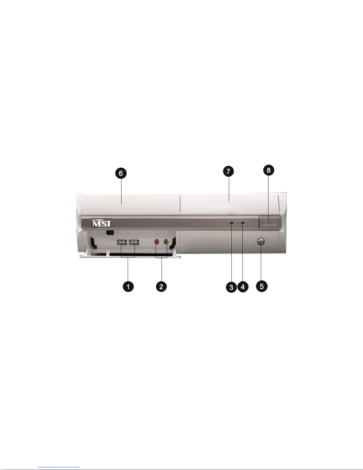
1.2 System Configuration
Front View
1. 2 x USB 2.0 Ports 5. Power Switch
2. Mic-in (pink), Line-out (green) 6. FDD (optional)
3. HDD LED 7. Optical Drive (optional)
4. Power LED 8. Optical Drive Eject/Close
Button
1-4
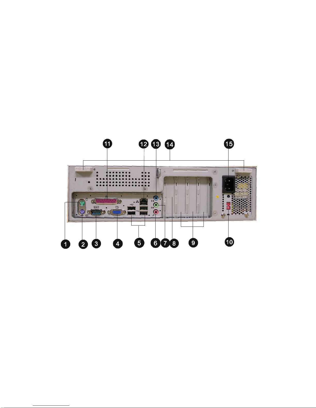
Rear View
Getting Started
1. PS/2 Mouse 9. PCI Slots
2. PS/2 Keyboard 10. AC Input Voltage Selector
3. Serial Port 11. Parallel Port
4. VGA Port 12. RJ-45 LAN Jack
5. 4 x USB 2.0 Ports 13. Line-in
6. Mic-in 14. Chassis Locks
7. Line-out 15. Power Jack
8. PCI Express x16 Slot
1-5
Chapter 1
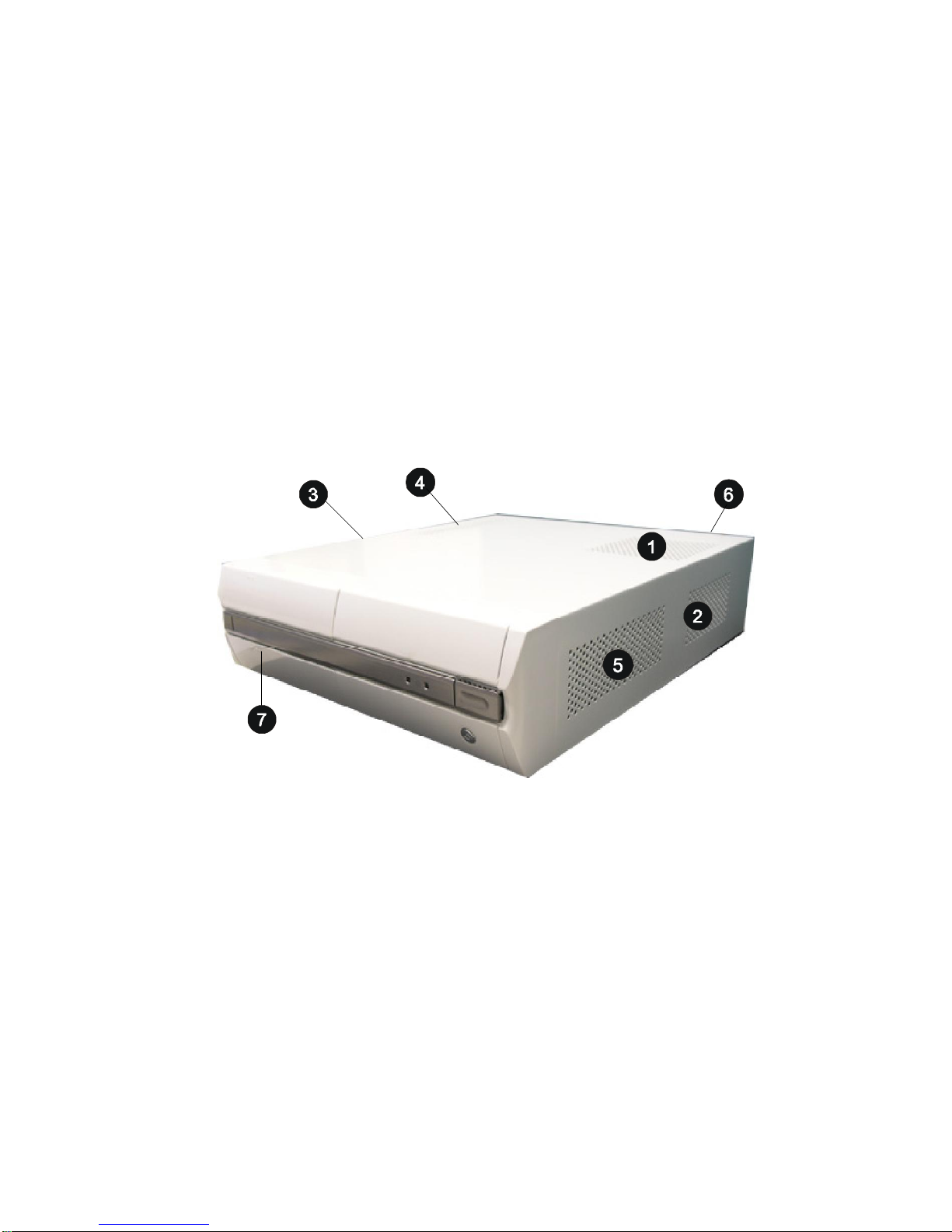
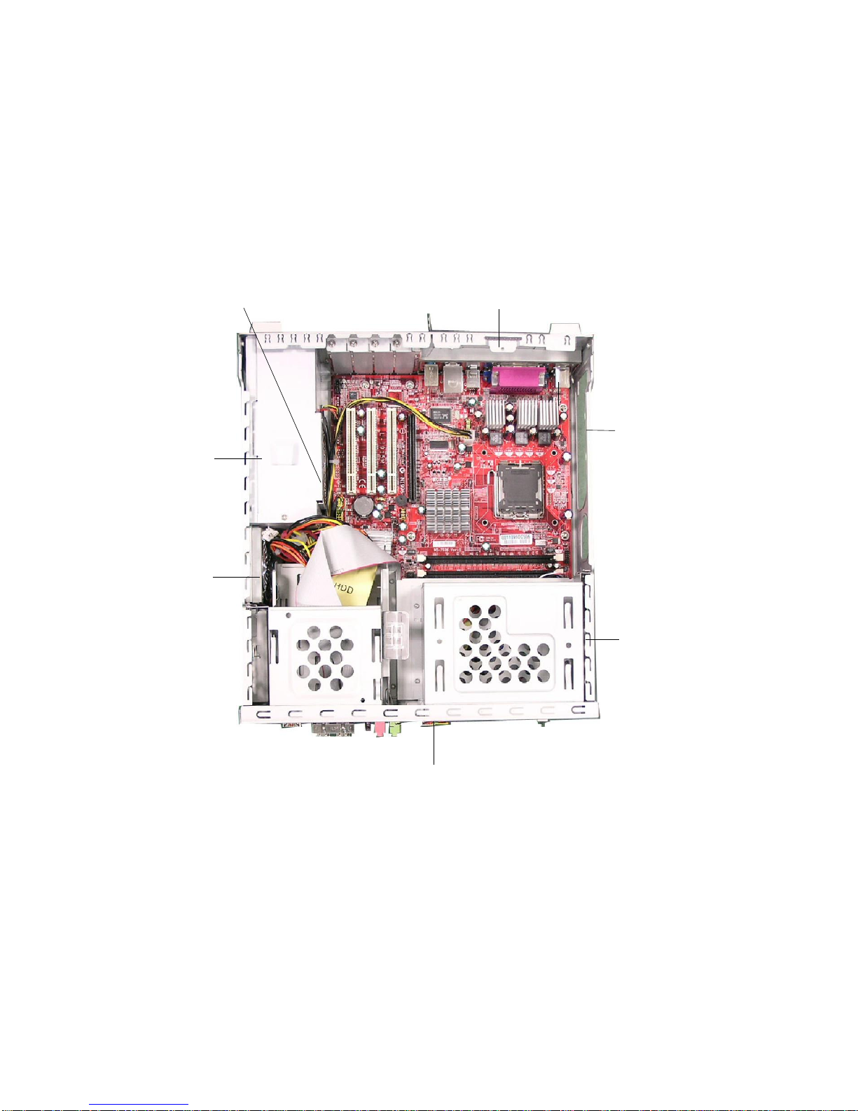
Chassis Design
† Dimension: 335mm (H) x 98mm (W) x 363mm (D)
† Minimized screw structure
† Detachable bay housing
† Multiple ventilation holes
1. CPU Fan Ventilation Hole 5. System Ventilation Hole
2. CPU Fan Ventilation Hole 6. System Ventilation Hole
3. System Fan Ventilation Hole 7. Front I/O Release Button
4. Power Supply Ventilation Hole
1-6
Getting Started
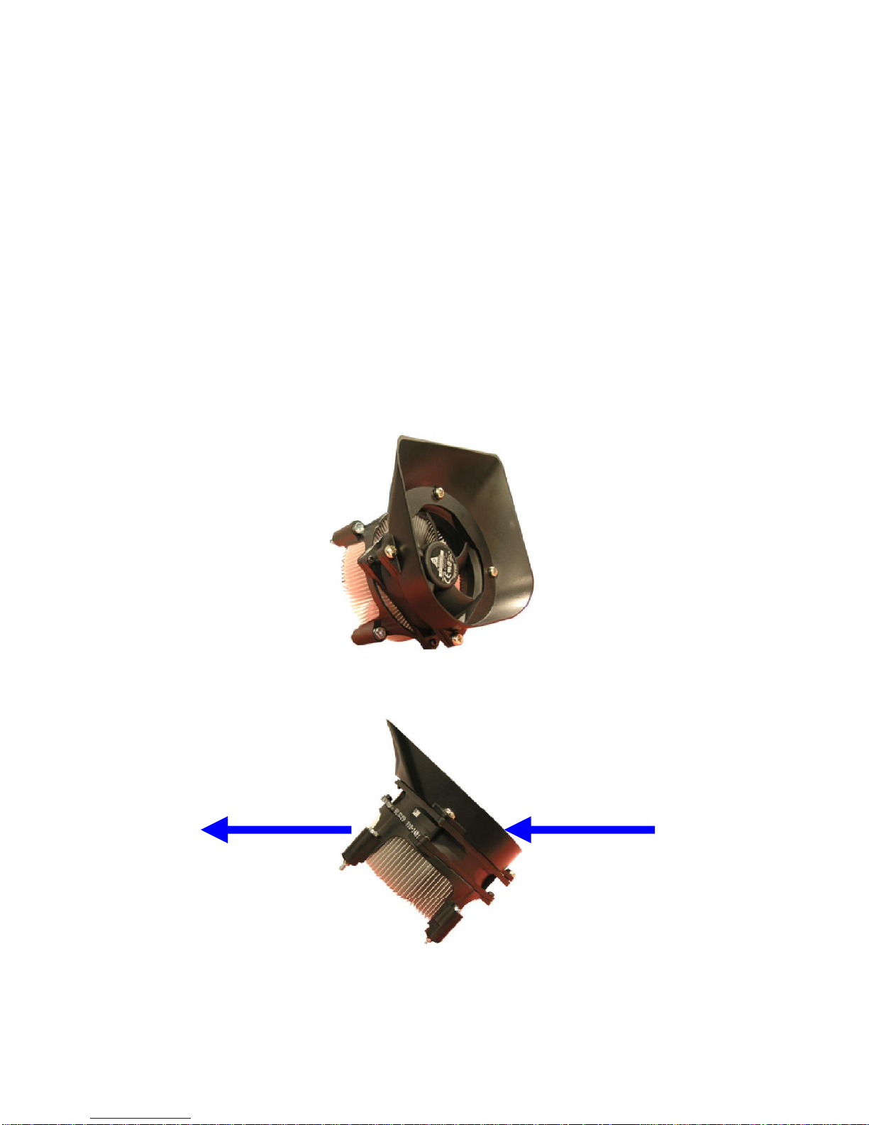
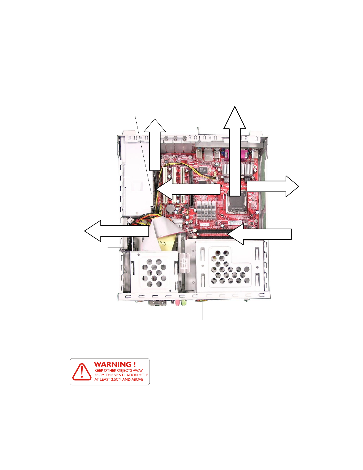
1.3 Thermal Solution
To prevent the system from overheating, we have adopted a specially designed CPU cooler (optional) and multiple ventilation holes for
better cooling effects. Of course, you can use the CPU cooler included
with the Intel® CPU.
The specially designed CPU cooler supports Intel® LGA775Prescott™ FSB800 and Celeron-D™ @ 800 MHz. The following figures
illustrate how the system fan effectively exhausts hot air through multiple ventilation holes.
CPU Fan
Air Flow Direction
Air Out
Air In
CPU Fan
1-7
Chapter 1
Power
Supply Fan
Power
Supply
Ventilation Hole
Ventilation
Hole
System
Fan
Ventilation
Hole
front panel
1-8
System Air Flow Direction
Power
Supply
Fan
Power
Supply
Getting Started
System Fan
front panel
After the installation is completed, please
keep other objects away from the ventilation hole at least 2.5cm and above. Do not
block the ventilation hole.
1-9

Introducing Mainboard
This chapter tells you basics of the CPU, memory modules,
and expansion cards, as well as how to setup the jumpers on the
mainboard. Also, it provides the instructions on connecting
the peripheal devices, such as the mouse, keyboard, etc.
While doing the installation, be careful in holding the components and follow the installation procedures.
2
Chapter 2
DDR2DDR
1
F_AUDIO
BIOS
Winbond
W83627THF
IDE 1
COM2
JLPC1
ATX_12V
PCI_E
915G/915GL
JFP
1
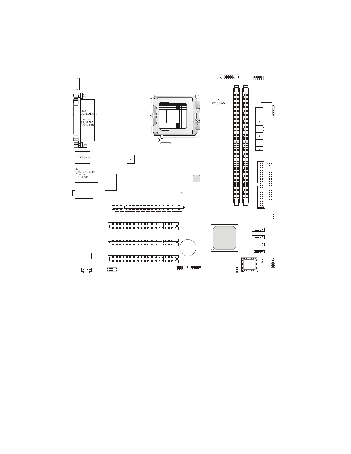
2.1 Mainboard Layout
T: mouse
B: keyboard
T:
Line-In
Line-Out
M:
B:Mic
Codec
RTL8100C
PCI Slot 1
PCI Slot 2
PCI Slot 3
LGA775 CPU Socket
BA TT
JCI1
IrDA
ATX
Power Supply
FDD
SYS_FAN
ICH6
+
SATA4
SATA3
SATA2
SATA1
CD_IN
F_USB2
F_USB1
CLR_CMOS
MS-7036 (V1.X) Mainboard
2-2
BIOS_WP
Introducing Mainboard
2.2 CPU
The mainboard supports Intel® Pentium 4 Prescott/Celeron-D
processor. The mainboard uses a CPU socket called LGA775. When you
are installing the CPU, make sure to install the cooler to prevent
overheating. If you do not have the CPU cooler, contact your dealer to
purchase and install them before turning on the computer.
MSI Reminds You...
Overheating
Overheating will seriously damage the CPU and system, always
make sure the cooling fan can work properly to protect the CPU
from overheating.
Replacing the CPU
While replacing the CPU, always turn off the ATX power supply or
unplug the power supply’s power cord from grounded outlet first
to ensure the safety of CPU.
Overclocking
This motherboard is designed to support overclocking. However,
please make sure your components are able to tolerate such
abnormal setting, while doing overclocking. Any attempt to operate beyond product specifications is not recommended. We do
not guarantee the damages or risks caused by inadequate
operation or beyond product specifications.
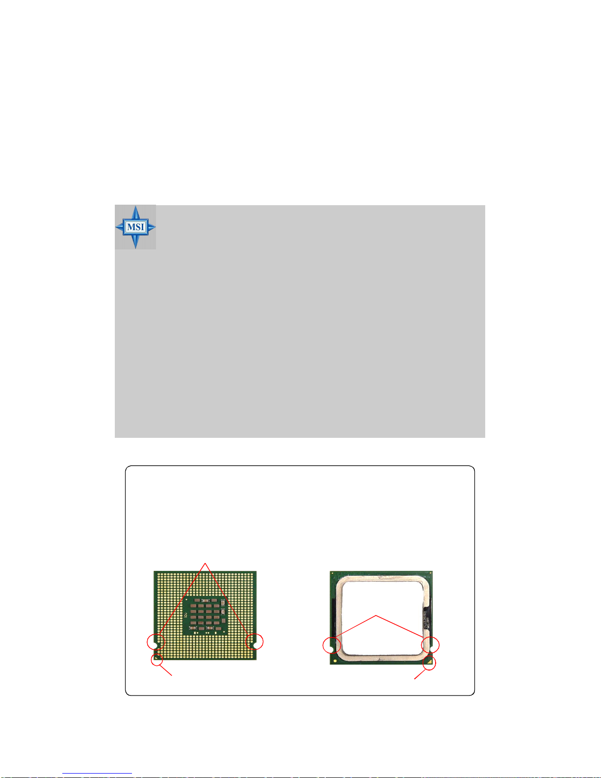
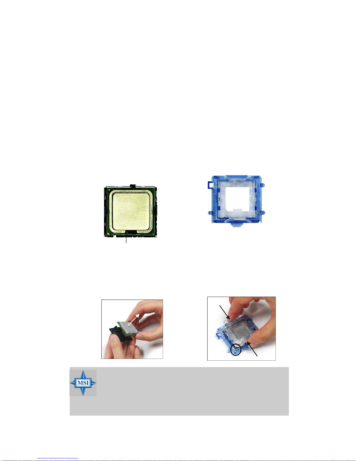
Introduction to LGA 775 CPU
The pin-pad side of LGA
775 CPU.
Alignment
The surface of LGA 775
CPU. Remember to apply
some silicon heat transfer
compound on it for better
heat dispersion.
Alignment Key
Yellow triangle is the Pin 1 indicator
Yellow triangle is the Pin 1 indicator
2-3
Chapter 2
CPU & Cooler Installation
When you are installing the CPU, make sure the CPU has a cooler
attached on the top to prevent overheating. If you do not have the cooler,
contact your dealer to purchase and install them before turning on the
computer. Meanwhile, do not forget to apply some silicon heat transfer
compound on CPU before installing the heat sink/cooler fan for better
heat dispersion.
Follow the steps below to install the CPU & cooler correctly. Wrong
installation will cause the damage of your CPU & mainboard.
1.The CPU has a land side cover on
the bottom to protect the CPU contact from damage. Rotate it to make
the pin 1 indicator (yellow triangle)
in the right-bottom corner.
land side cover
3.Use 2 hands to remove the land side
cover (if any). Please note not to
touch the pins.
2.Take out the accompanying CPU Clip
and rotate it for the same direction as
the CPU (Pin 1 indicator is in the left-
bottom corner).
4.Align the two pin 1 indicators (the
triangles on the CPU & the CPU Clip),
and use the CPU Clip to clip the CPU
up, pressing the clips on both sides
to the center, as the arrows shown.
MSI Reminds You...
1.Confirm if your CPU cooler is firmly installed before turning on
your system.
2.Do not touch the CPU socket pins to avoid damaging.
3. The availability of the CPU land side cover depends on your CPU
packing.
2-4
Introducing Mainboard
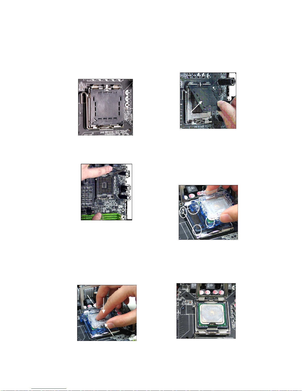
5.The CPU socket has a plastic cap on
it to protect the contact from damage.
Before you have installed the CPU,
always cover it to protect the socket
pin.
7.Lift the load lever up and open the
load plate.
6.Remove the cap from lever
hinge side (as the arrow
shows). The pins of socket
reveal.
8.Correctly align the triangle of
CPU Clip with the CPU chamfer,
and the square on the CPU Clip
to the hook of the socket.
9.Use your thumb and the middle fingers to push the clips to release the
CPU, then press down the CPU with
your index finger to allow the whole
module to be installed onto the CPU
socket.
10.The CPU is installed well on
the CPU socket.
2-5
Chapter 2
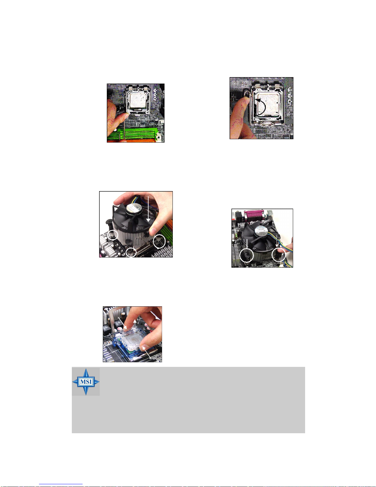
11.Visually inspect if the CPU is seated
well into the socket, then remove the
CPU Clip with 2 fingers. Then cover
the load plate onto the package.
12. Press down the load lever
lightly onto the load plate, and
then secure the lever with the
hook under retention tab.
The following installation example is Intel CPU cooler.
13. Align the holes on the mainboard with
the cooler. Push down the cooler until
its four clips get wedged into the holes
of the mainboard.
14.Press the four hooks down to
fasten the cooler. Then rotate
(with a tack screwdriver) the
locking switch (refer to the correct direction marked on it) to
lock the hooks.
Note:If you want to uninstall the
CPU, align the 4 points (see
Point 8 for details) again and
push the clip to lift up the CPU.
MSI Reminds You...
1.Check the information in PC Health Status of H/W Monitor in
BIOS (Chapter 4) for the CPU temperature.
2. Whenever CPU is not installed, always protect your CPU socket
pin with the plastic cap covered to avoid damaging.
3. Please note that the mating/unmating durability of the CPU is 20
cycles. Therefore we suggest you do not plug/unplug the CPU too
often.
locking
2-6
Introducing Mainboard
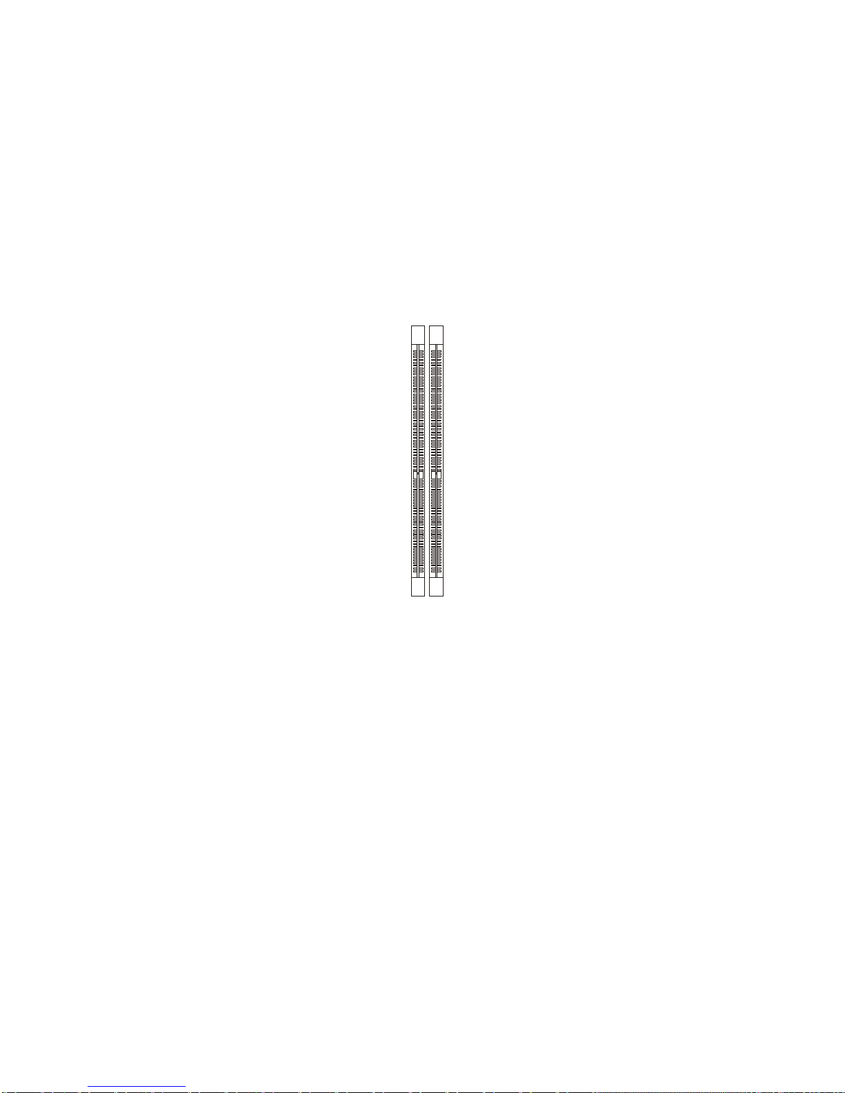
2.3 Memory
The mainboard provides two 184-pin unbuffered DDR266/DDR333/
DDR400 DDR SDRAM, and supports the memory size up to 2GB without
ECC. To operate properly, at least one DIMM module must be installed.
(For the updated supporting memory modules, please visit http://www.
msi.com.tw/program/products/mainboard/mbd/pro_mbd_trp_list.php )
DDR DIMM Slots
(DIMM 1~2)
Introduction to DDR SDRAM
DDR (Double Data Rate) SDRAM is similar to conventional SDRAM, but
doubles the rate by transferring data twice per cycle. It uses 2.5 volts as
opposed to 3.3 volts used in SDR SDRAM, and requires 184-pin DIMM
modules rather than 168-pin DIMM modules used by SDR SDRAM.
2-7
 Loading...