

MSI ATX BX7, MS-6147 User Manual

CHAPTER 1 INTRODUCTION
1-1
The MICRO A TX BX7 mainboard is a high-performance personal computer
mainboard based on the Intel® Pentium® II processor. This mainboard
combines leading edge AGP A TI® 3D RAGE PRO/RAGE PRO Turbo technology in graphics and Creative® ES1371/ES1373(reserved) PCI technology in
audio. The Intel® Pentium® II processor supports MMX
TM
(Multimedia
Extension) technology .
The mainboard uses the highly integrated Intel® 82443BX AGP chipset to
support the PCI/ISA and Green standards, and to provide the Host/AGP
bridge. The Intel® 82371EB chipset integrates all system control functions
such as ACPI (Advanced Configuration and Power Interface). The ACPI
provides more Energy Saving Features for the OSPM(OS Direct Power
Management) function. The Intel® 82371EB chipset also improves the IDE
transfer rate by supporting Ultra DMA/33 IDE that transfers data at the rate
of 33MB/s.
The mainboard also supports the System Hardware Monitor Controller as an
optional function. Its functions include: CPU /power supply/chassis fan
revolution detect, CPU/system voltage monitor, system temperature monitor ,
and chassis intrusion detect(optional).
Chapter 1
INTRODUCTION

CHAPTER 1 INTRODUCTION
1-2
1.1 Mainboard Features
CPU
l Slot 1 for Intel
®
Pentium® II/CeleronTM processor .
l Supports 233MHz, 266MHz, 300MHz, 333MHz, 350MHz, 400MHz,
450MHz, and faster .
Chipset
l Intel
®
82443BX/PIIX4E chipset.
Clock Generator
l 66/68/75/83/100/112/133MHz clocks are supported.
Main Memory
l Supports four memory banks using two 168-pin unbuffered DIMM.
l Supports a maximum memory size of 256MB (8M x 8) or 512MB (16M x 4)
registered DIMM only .
l Supports ECC(1-bit Error Code Correct) function.
l Supports 3.3v SDRAM DIMM.
Slots
l Three 32-bit Master PCI Bus slots and one 16-bit ISA bus slots.
l Supports 3.3v/5v PCI bus Interface.
On-Board IDE
l An IDE controller on the Intel
®
PIIX4E PCI Chipset provides IDE HDD/
CD-ROM with PIO, Bus Master and Ultra DMA/33 operation modes.
l Can connect up to four IDE devices.
On-Board Peripherals
l On-Board Peripherals include:
- 1 floppy port supports 2 FDD with 360K, 720K, 1.2M, 1.44M and
2.88Mbytes.
- 1 serial port (COM A) + 1 serial connector (COM B)
- 1 parallel port supports SPP/EPP/ECP mode
- 2 USB ports
- 1 IrDA connector for SIR.

CHAPTER 1 INTRODUCTION
1-3
VGA
l ATI
®
3D RAGE PRO/RAGE PRO TURBO 2x
- Running on AGP BUS.
- Onboard 8MB SDRAM.
- 3D Acceleration.
- AGP 2x mode (133MHz) support pipelined and sideband protocols.
Sound
l Creative
®
ES1371/ES1373 (reserved)
- Running on PCI BUS.
- 64 V oice and AC3 Capable (ES1373 only)
- Support Direct Sound and Direct Sound 3D
- AC97’ Compliant
I/O Chip
l Winbond
®
multi super I/O W83977F
- 2M bps fast tape drive, IRQ sharing
- Device Power Management
- Real time clock (256 bytes RAM)
- 8042-based keyboard controller (support PS/2 mouse)
BIOS
l The mainboard BIOS provides “Plug & Play” BIOS which detects the
peripheral devices and expansion cards of the board automatically.
l The mainboard provides a Desktop Management Interface(DMI) function
which records your mainboard specifications.
l ACPI(Advanced Configuration and Power Interface) feature.
Dimension
l MICRO ATX Form Factor : 24.4cm(L) x 19.2cm(W) x 4 layers PCB
Mounting
l 6 mounting holes.

CHAPTER 1 INTRODUCTION
1-4
System Hardware Monitor (optional)
l CPU/Power Supply/Chassis Fan Revolution Detect
l CPU Fan Control (the fan will automatically stop when the system enters
suspend mode)
l System Voltage Detect
l CPU Overheat W arning.
l Display Actual Current Voltage
Other Features
l Keyboard Password Wake-Up (reserved)
l LAN W ake-Up
l Internal/External Modem W ake-Up
CHAPTER 1 INTRODUCTION
1-5
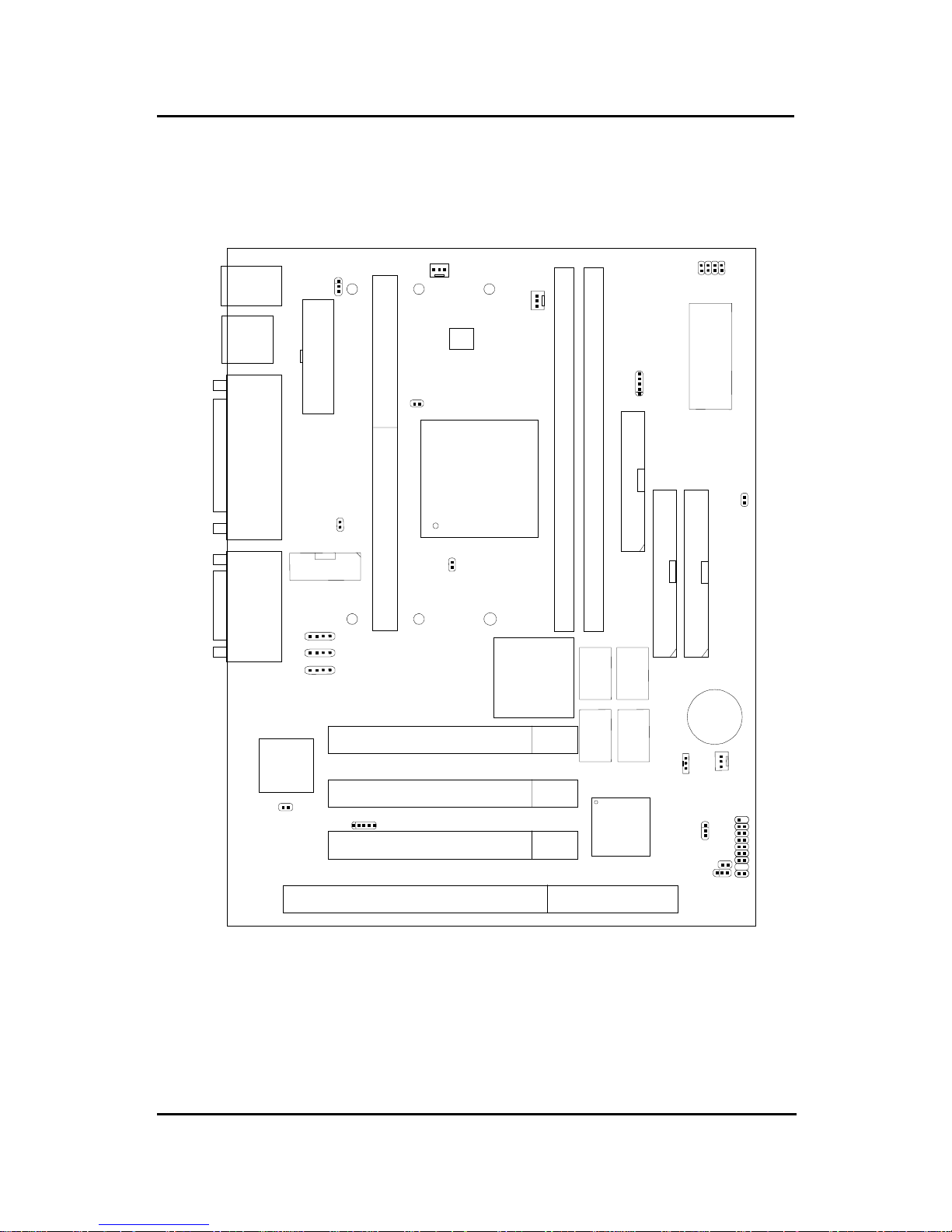
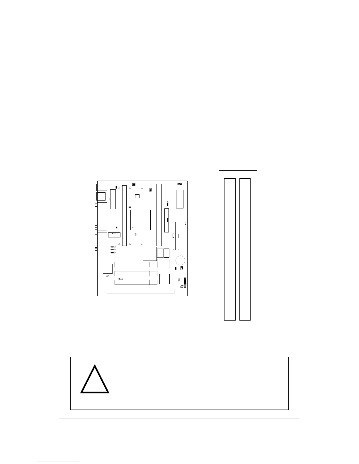
PCI SLOT 3
PCI SLOT 2
PCI SLOT 1
ISA SLOT 1
ATX
Power Supply
FW82443BX
SLOT 1
DIMM 2
Top: mouse
Bottom:
keyboard
Top: Port 1
USB
DIMM 1
IDE2
Bottom:
Port 2
IDE1
FDD
ATI 3D
RAGE PRO
FW82371EB
JMDM1
Creative
ES1371
JP1
SYSFAN
JFP1
JGS1
JGL1
JBAT1
JWOL1
BIOS
J6: MDM_IN
J5: AUX_IN
COM 2
CPUFAN
JSOR1
JRMS1
SW1
PSFAN
IR
BATT
+
Top: LPT
Bottom:
COM A
VGA Port
Top: Midi/
Game Port
Bottom:
Line-Out
Line-In
Mic
1.2 Mainboard Layout
MS-6147 MICRO ATX BX7 Mainboard
1
4
JP2
J8: CD_IN
J3
SDRAM
SDRAM
JVSB1
(Reserved)
System
Hardware
Monitor
(optional)
SDRAM
SDRAM

CHAPTER 2 HARDWARE INSTALLATION
2-1
Chapter 2
HARDWARE INSTALLATION
2.1 Central Processing Unit: CPU
The mainboard operates with Intel® Pentium® II/CeleronTM processor. The
mainboard uses a CPU Slot called Slot 1 for easy CPU installation and a
jumper switch (SW1) to set the proper speed for the CPU. The CPU should
always have a Heat Sink and a cooling fan attached to prevent overheating.
CHAPTER 2 HARDWARE INSTALLATION
2-2
2.1-1 CPU Installation Procedures
A. OEM Pentium
®
II Processor Installation Procedures
Different kinds of Pentium® II processor that is currently used: the OEM
version, the Boxed version, and CeleronTM. OEM Pentium® II Processor has
no Heat Sink, Fan and Heat Sink Support, the Boxed Pentium® II Processor
is provided with Heat Sink w/ fan and Heat Sink Support, while the
CeleronTM processor is a plain processor card without cover or heatsink..
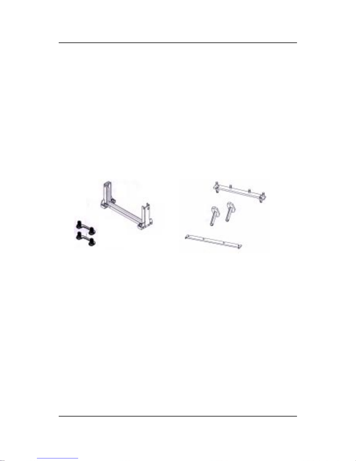
Required Things:
Pentium® II processor - Processor .
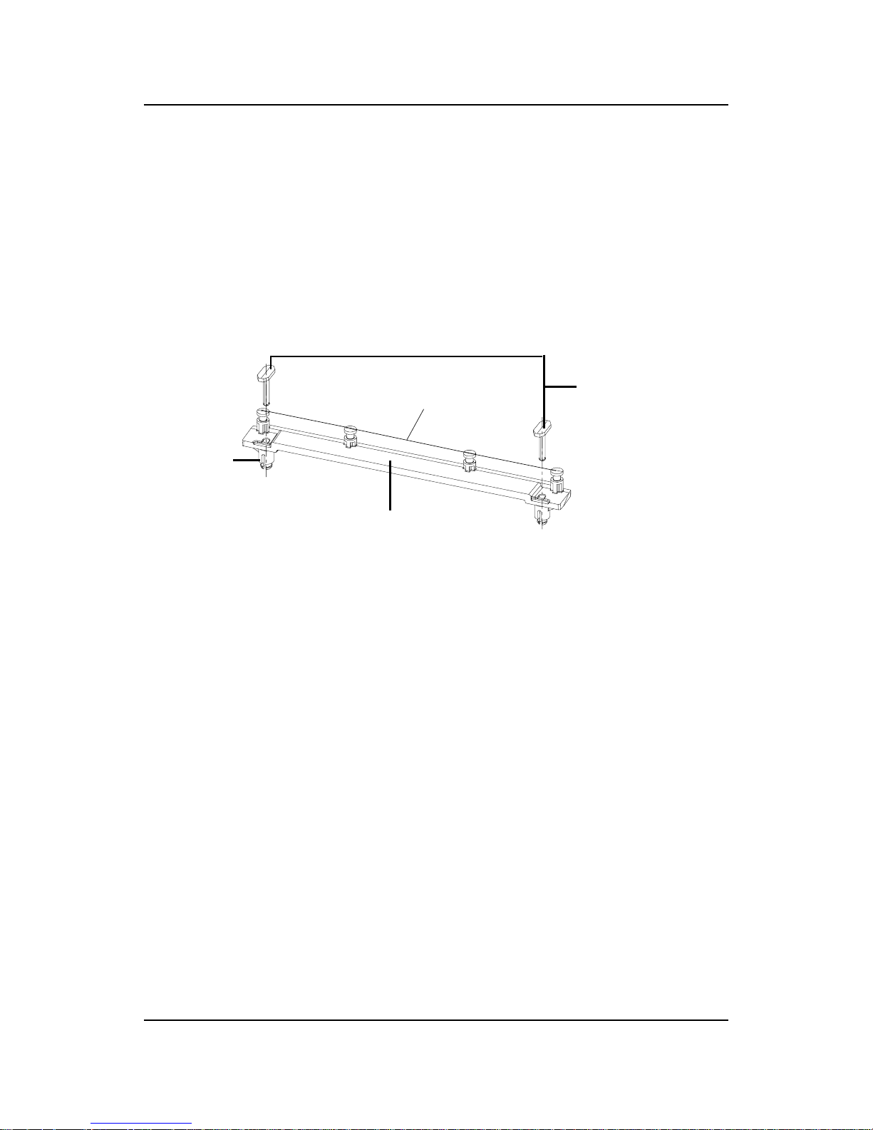
*Retention Mechanism(RM) - Plastic Guide that holds the S.E.C. Catridge
in the Slot 1 connector.
*Retention Mechanism Attach Mount(RMAM) - Bolt/Bridge assemblies
inserted up through the bottom of the
motherboard. RM secures to RMAM ( 2
RMAM required per RM ).
*Heat Sink Support Base (HSSBASE) - Plastic support bar mounted to
the mainboard under the ATX heatsink.
(One leg is always bigger than the other one)
Processor
Lock
Retention
Mechanism
Pentium® II
Processor
Heat Sink
W/Fan
Notch Hole
Heat Sink
Support Base
Heat Sink
Support Pin
Heat Sink
Support
Top Bar
CHAPTER 2 HARDWARE INSTALLATION
2-3
*Heat Sink Support Pin (HSSPIN) - Plastic pins inserted through the
HSSBASE to secure it to the mainboard (2
required per Assembly).
*Heat Sink Support T op Bar (HSSTOP) - Plastic bar that clips onto the
HSSBASE through the fins on the ATX
heatsink.
**Heat Sink w/ fan - Heat Sink that can be attached to the Pentium® II
processor with metal clip.
Note: * Provided by MSI mainboard.
** Provided by Special request.
RM
HSSPIN
HSSTOP
HSSBASE
RMAM
CHAPTER 2 HARDWARE INSTALLATION
2-4
SLOT1
Retention
Mechanism
ê
ê
Key
êê
Retention
Mechanism
Attach Mount
Notch
Key
Step 1: Insert the Retention Mechanism Attach Mount at the bottom
of the mainboard.
Step 2: Install the Retention Mechanism.
Look for the key on Slot 1, and match it with the Notch Key on the
Retention Mechanism for proper direction. Then, attach the
Retention Mechanism to the Retention Mechanism Attach Mount.
Use a Screwdriver to secure the Retention Mechanism.
CHAPTER 2 HARDWARE INSTALLATION
2-5
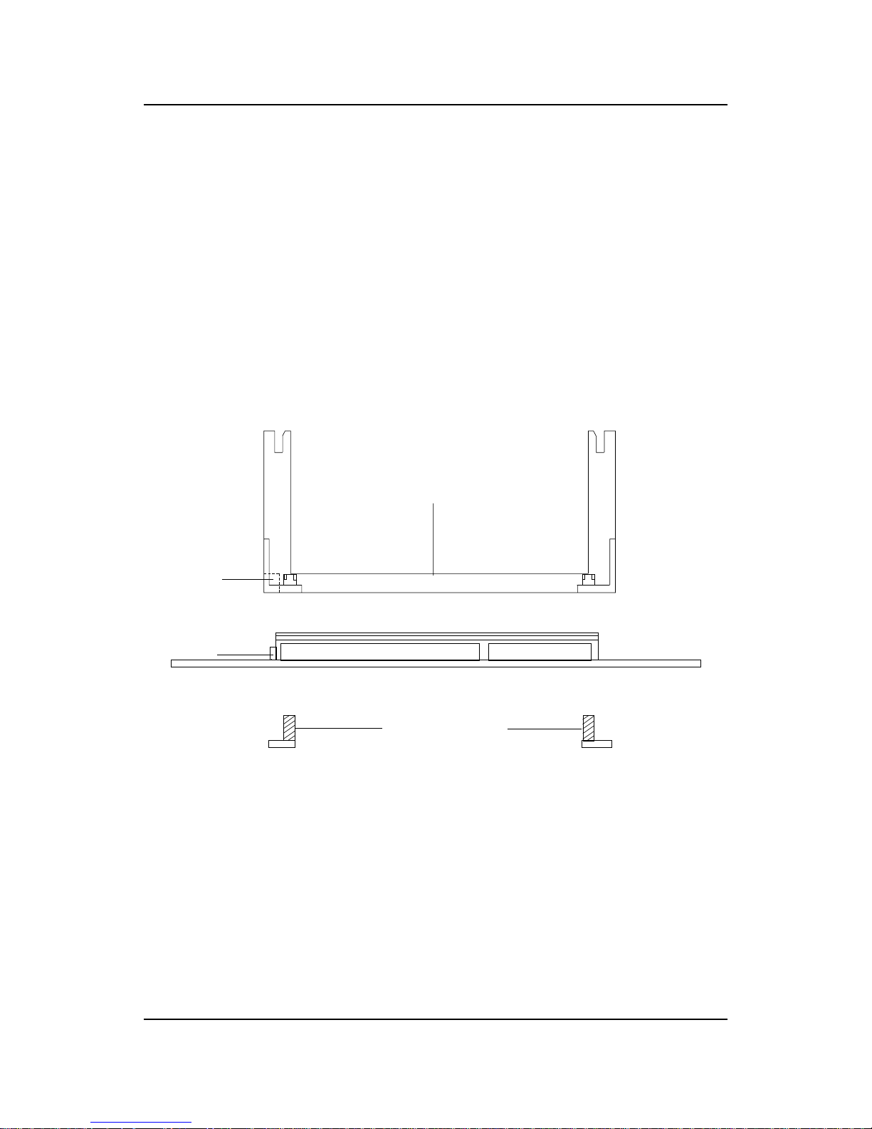
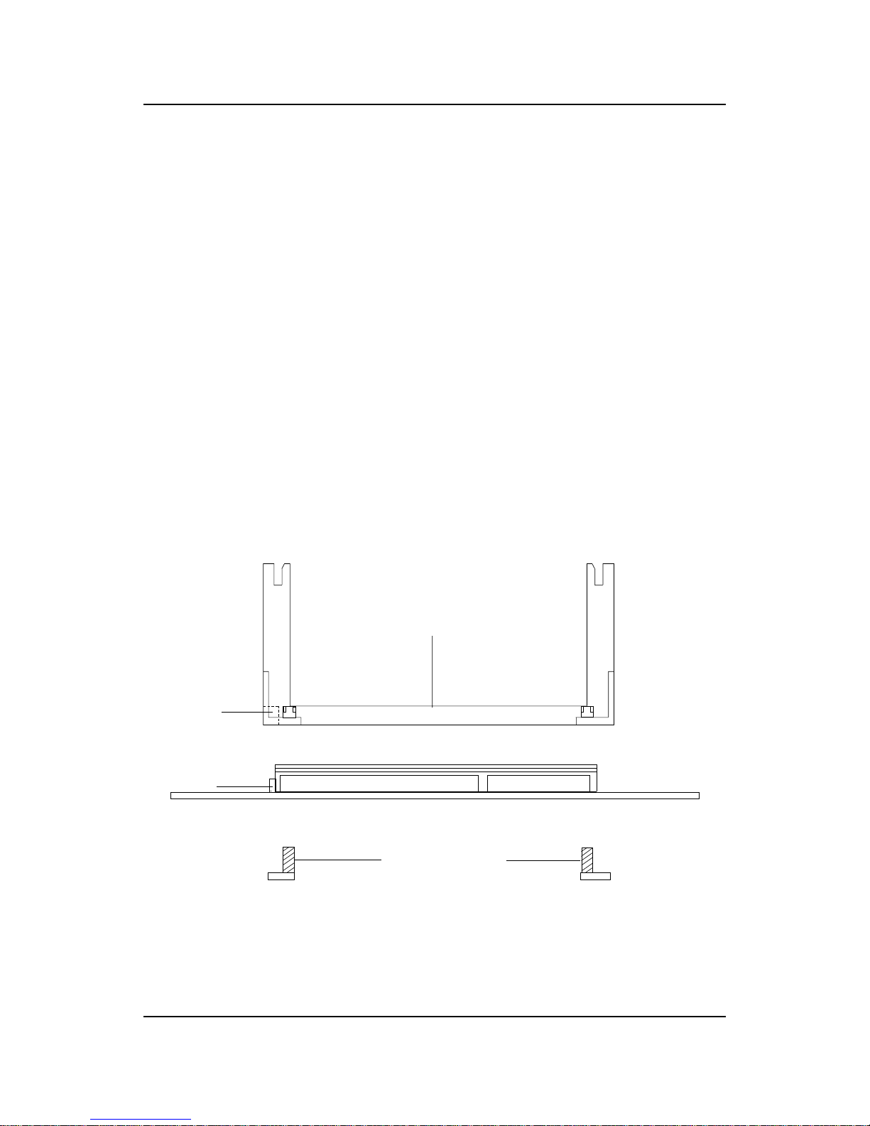
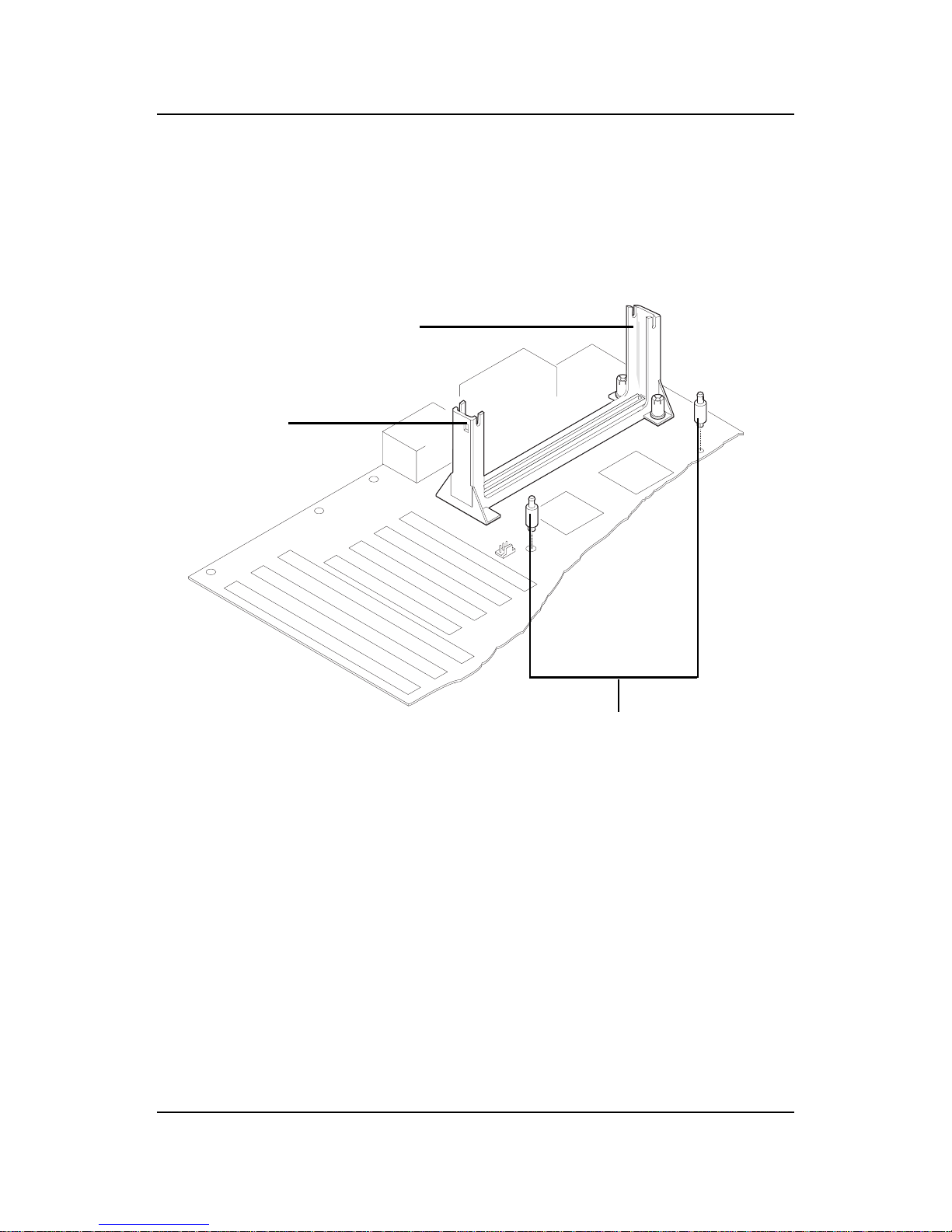
Step 3: Install the Heat Sink Support Base.
Look for the T wo holes across Slot 1, and match it with the Two legs
of the Heat Sink Support Base for the proper direction. T ake note
that one hole/leg is bigger than the other. The Four top pins of the
Heat Sink Support Base should also be oriented towards Slot 1.
Push the Heat Sink Support Base onto the mainboard, until you hear
a click sound. Check for a perfect fit.
Step 4: Install the Heat Sink Support Pin.
Push the Heat Sink Support Pins onto the two holes of the Heat Sink
Support Base. Check for a perfect fit. These pins are used to secure
the Heat Sink Support Base.
Heat Sink
Support Base
Heat Sink
Support Pin
Leg
pins
CHAPTER 2 HARDWARE INSTALLATION
2-6
S.E.C. Cartridge - Thermal
P
Isometric View
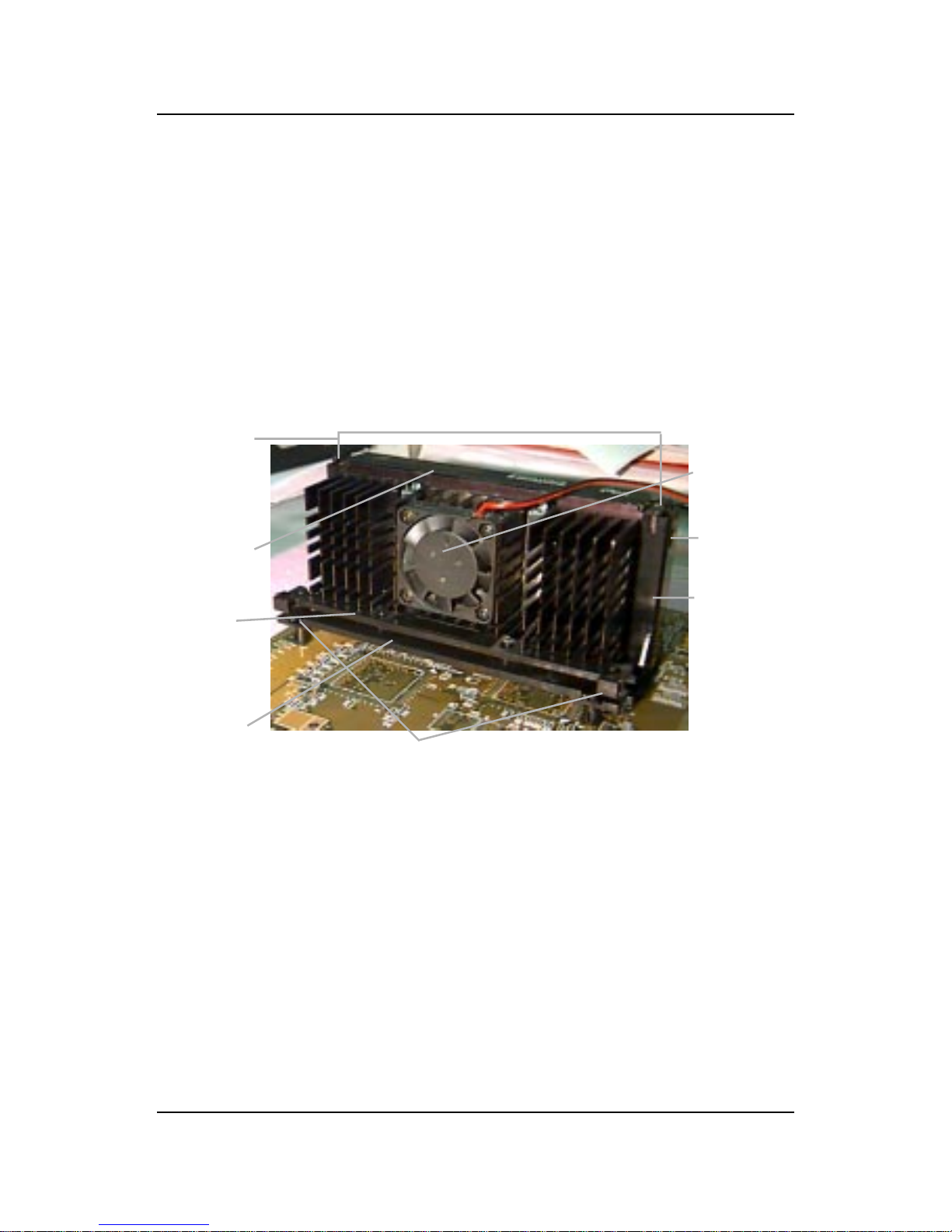
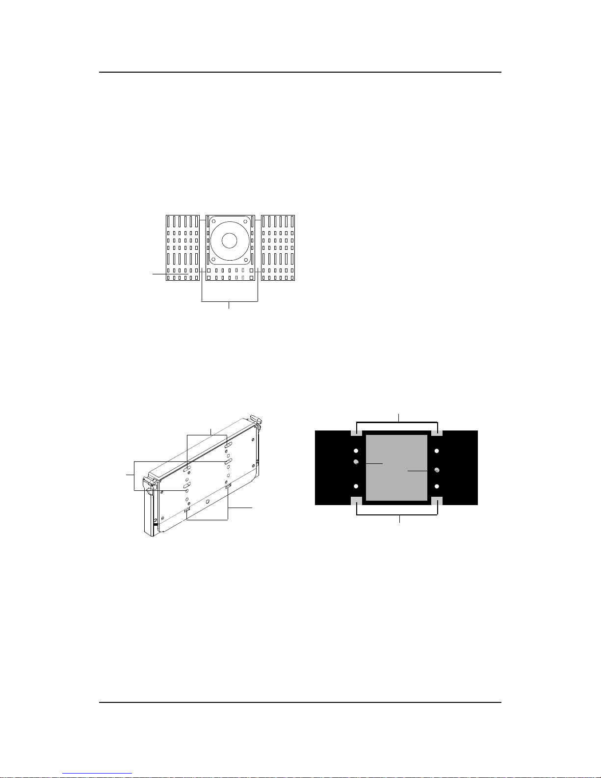
Step 5: Install the Heat Sink with Fan to the Processor .
Push down the metal clips, so that they are in line with the back of
the Heat Sink. Be careful, so as not detach the metal clips from the
Heat Sink.
In case the metal clips are detached from the Heat Sink, re-attach
them. Look for the arrow on the metal clip. This arrow should be
pointing down and aligned with the Heat Sink Support Base Holder.
Attach the Heat Sink to the processor.
- Look at the back of the Heat Sink and take note of the 2 secure
posts. Insert these 2 Secure posts to the 2 secure holes on the
back of the processor.
- Align the ears of the metal clips with the clip holders on the back of
the processor. Use a screw driver to push the metal clips onto the
clip holders. Check for a perfect fit.
Pentium® II Processor (Back)
â
The arrow
should be
pointing
down.
Metal Clips
Heat Sink w/ Fan
Metal Clips Ear
Metal Clips Ear
Secure
Posts
Heat Sink w/ Fan(Back)
Heat Sink
Base Holder
Secure
holes
Clip Holder
Clip Holder
CHAPTER 2 HARDWARE INSTALLATION
2-7
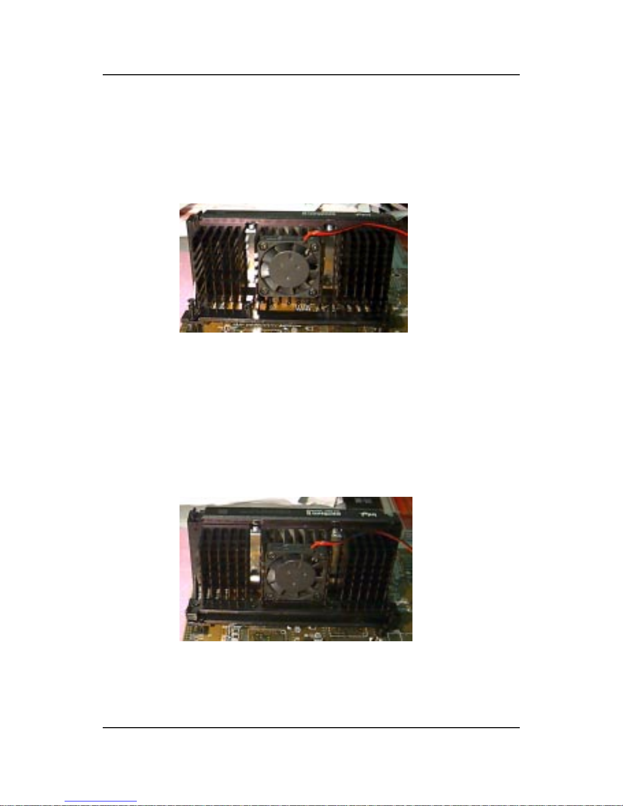
Step 6: Install the Processor .
Unlock the Processor by pushing in the Processor Locks.
Insert the Processor like inserting a PCI or an ISA card.
Step 7: Lock the Processor Locks.
Secure the CPU by pulling the Processor Locks out.
è
ç
ç
è
CHAPTER 2 HARDWARE INSTALLATION
2-8
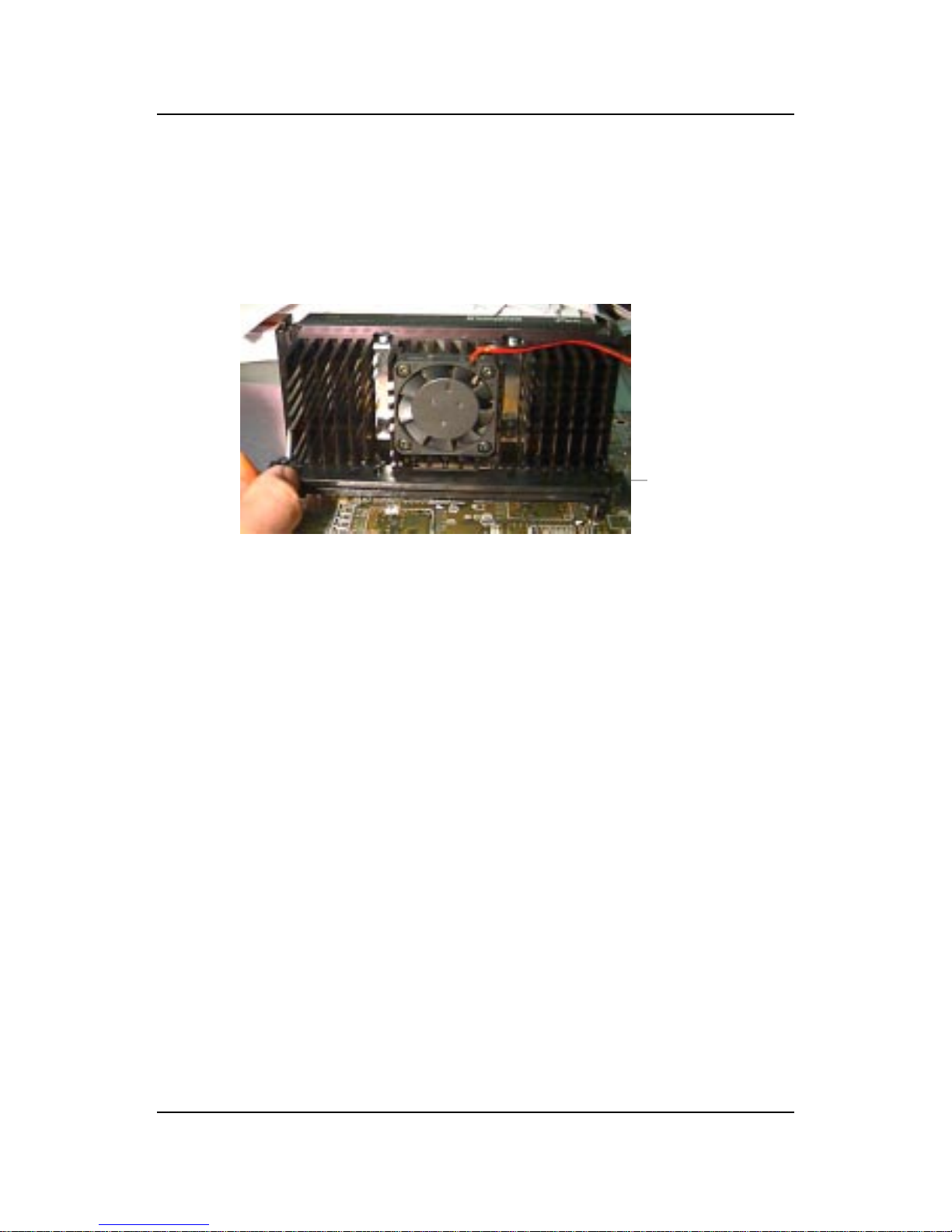
Step 8: Install the Heat Sink Support T op Bar .
Push the Heat Sink Support T op Bar to the Heat Sink Support Base,
Until you hear a “click” sound. Check for a perfect fit.
The installation is now complete.
Heatsink
Support Top
Bar
CHAPTER 2 HARDWARE INSTALLATION
2-9
B. Boxed Pentium® II Processor Installation Procedures
The Boxed Pentium® II Processor has a built- in Fan and Heat Sink. It also
has a Heat Sink Support. So if you’re going to use a Boxed PentiumTM II
Processor, all you need is the Retention Mechanism.
SLOT1
Retention
Mechanism
ê
ê
Key
êê
Retention
Mechanism
Attach Mount
Notch
Key
Step 1: Insert the Retention Mechanism Attach Mount at the bottom
of the mainboard.
Step 2: Install the Retention Mechanism.
Look for the key on Slot 1, and match it with the Notch Key on the
Retention Mechanism for proper direction. Then, attach the
Retention Mechanism to the Retention Mechanism Attach Mount.
Use a Screwdriver to secure the Retention Mechanism.
CHAPTER 2 HARDWARE INSTALLATION
2-10
Step 3: Install the Heat Sink Support Base.
Look for the 2 holes across Slot 1, and match it with the 2 Heat Sink
Support Base. Take note that one hole/base is bigger than the other.
Push the Heat Sink Support Base onto the mainboard, until you hear
a click sound. Check for a perfect fit.
PC-3742
Retention
Mechanism
Notch
Hole
Heat Sink
Support Base
CHAPTER 2 HARDWARE INSTALLATION
2-11
PC-3743
Heat Sink
Support Lock
Intel® Boxed
Pentium® II
Processor
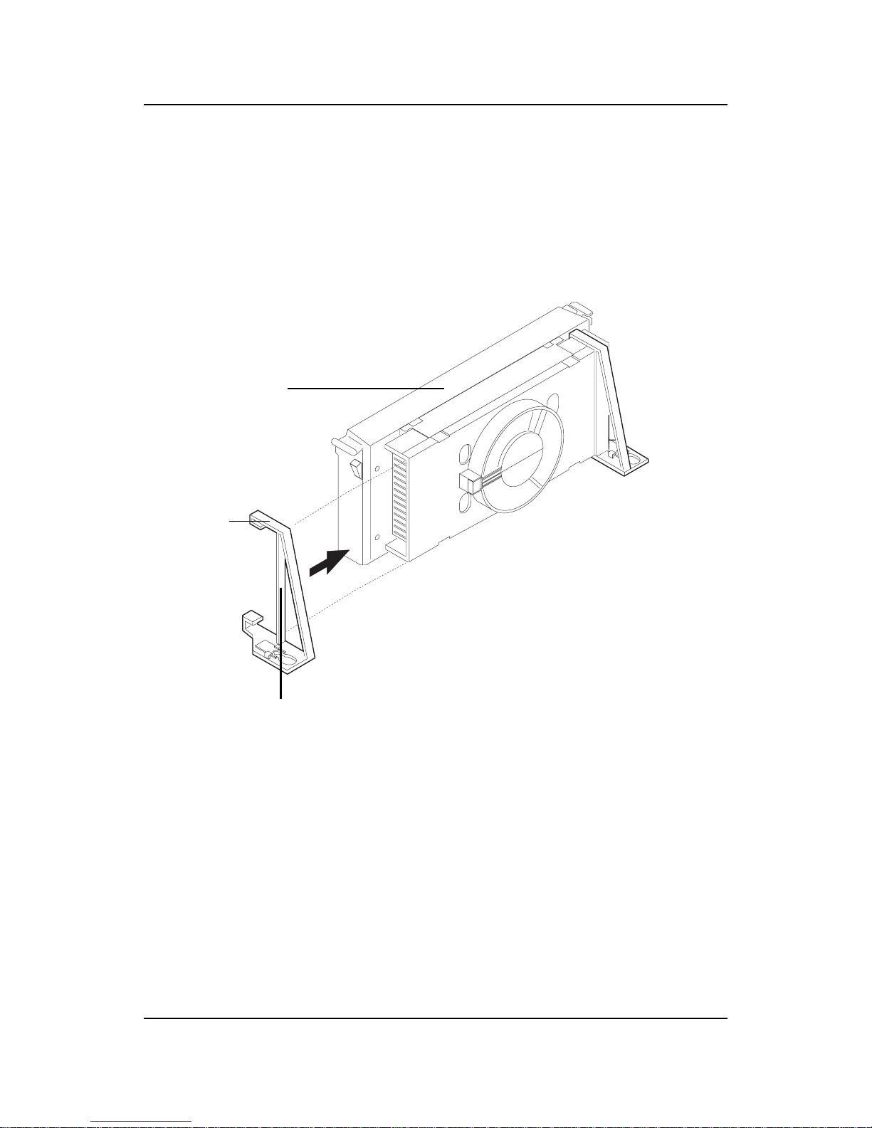
Step 4: Install the Heat Sink Support.
Attach the 2 Heat Sink Supports to the sides of the Processor. These
Heat Sink Supports will fit in any direction, so be sure that the Heat
Sink Support Locks are oriented outwards for the proper direction.
Heat Sink
Support
CHAPTER 2 HARDWARE INSTALLATION
2-12
PC-3744
Processor
Lock
Heatsink
Support
Lock
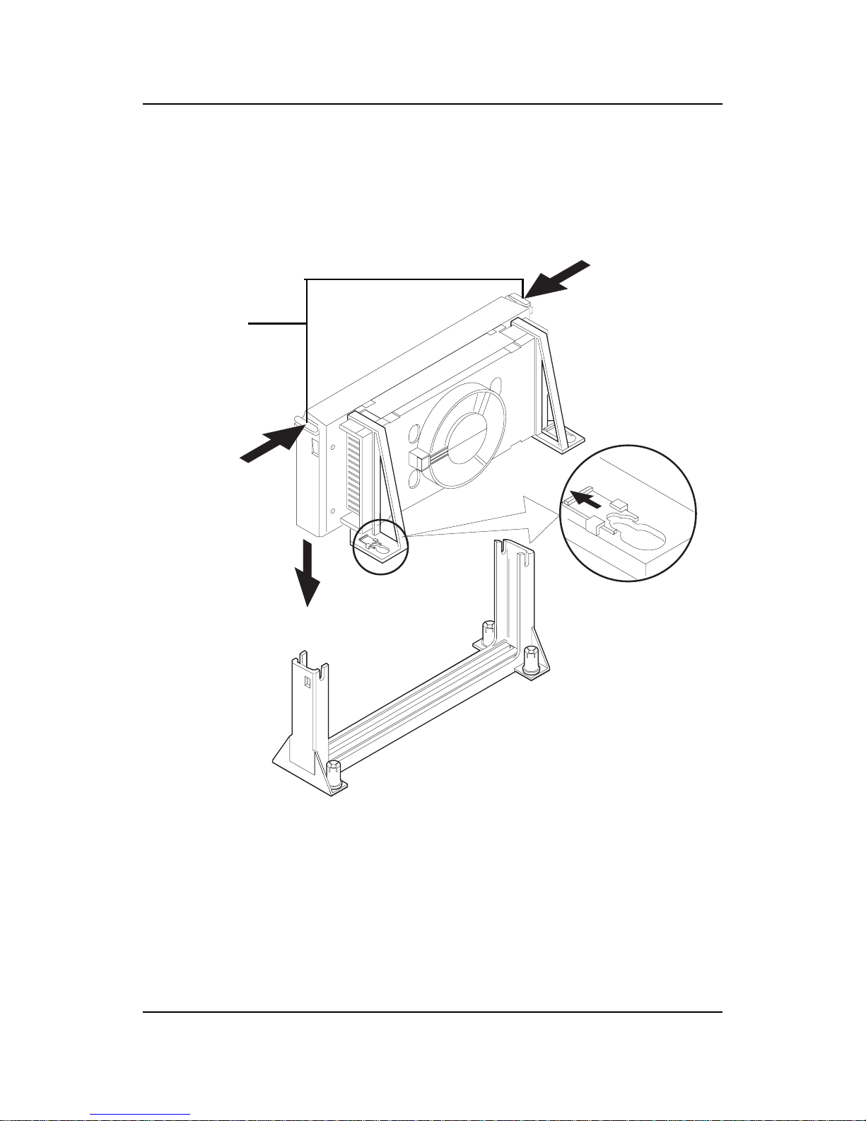
Step 5: Unlock the Processor Locks and Heat Sink Support Locks.
Push in the Processor Locks. Open the Heat Sink Support Locks.
Step 6: Insert the Processor like inserting a PCI or an ISA card.
CHAPTER 2 HARDWARE INSTALLATION
2-13
PC-3745
Step 7: Lock the Processor Locks and Heat Sink Support Locks
Secure the CPU by pushing out the Processor Locks. Close the Heat
Sink Support Locks.
The installation is now complete.
CHAPTER 2 HARDWARE INSTALLATION
2-14
SLOT1
Retention
Mechanism
ê
ê
Key
êê
Retention
Mechanism
Attach Mount
Notch
Key
Step 1: Insert the Retention Mechanism Attach Mount at the bottom
of the mainboard.
Step 2: Install the Retention Mechanism.
Look for the key on Slot 1, and match it with the Notch Key on the
Retention Mechanism for proper direction. Then, attach the
Retention Mechanism to the Retention Mechanism Attach Mount.
Use a Screwdriver to secure the Retention Mechanism.
C. OEM CeleronTM Processor Installation Procedures
CHAPTER 2 HARDWARE INSTALLATION
2-15
Step 3: Install the MSI Heat Sink (optional) to the Processor .
Push down the plastic clips, so that they are in line with the hole on
the processor . Check for perfect fit.
Step 4: Install the Processor .
Insert the Processor like inserting a PCI or an ISA card.
Step 5: Lock the Processor
Lock the processor by putting the Retention Cap provided. Take
note of the two plastic lock at the side of the Retention Cap. This
two plastic lock should be aligned properly into the Retention
Mechanism notch hole.
ê
ê
Retention Cap
ê
Heat Sink
Celeron
TM
processor
ê
plastic Clip
Plastic
Lock
Notch
Hole
Notch
Hole
The instruction procedure may
vary depending on the Heat Sink
that you’re using.
CHAPTER 2 HARDWARE INSTALLATION
2-16
Procedure for detaching the Retention Cap:
T o remove the Retention Cap, you need a Screw Driver (0.3 cm) tip.
- Insert the screw driver into the retention cap notch hole.
- Push the retention cap plastic lock inward.
- Pull the retention cap upward.
Retention Cap
(Top View)
Notch
Hole
CHAPTER 2 HARDWARE INSTALLATION
2-17
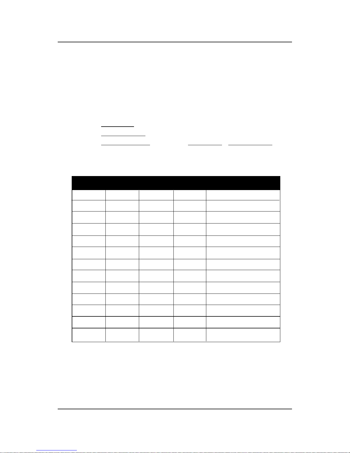
2.1-2 CPU Core Speed Derivation Procedure
1 2 3 4 Core/Bus Ratio
ON OFF ON ON 2 .5
ON ON OFF ON 3
ON OFF OFF ON 3. 5
ON ON ON OFF 4
ON OFF ON OFF 4 . 5
ON ON OFF OFF 5
ON OFF OFF OFF 5 . 5
OFF ON ON ON 6
OFF OFF ON ON 6. 5
OFF ON OFF ON 7
OFF OFF OFF ON 7 . 5
OFF ON ON OFF 8
1 . The DIP Switch SW1 (1, 2, 3, and 4) is used to set the Core/Bus (Fraction)
ratio of the CPU. The actual core speed of the CPU is the Host Clock
Frequency multiplied by the Core/Bus ratio. For example:
If CPU Clock = 66MHz/100MHz
Core/Bus ratio = 4
then CPU core speed = Host Clock x Core/Bus ratio
= 66MHz x 4/100MHz x 4
= 266MHz/400MHz
SW1 CPU
Note: The CPU Bus Frequency is set at 66MHz or 100MHz by CPU
default.
ON - Short OFF - Open
CHAPTER 2 HARDWARE INSTALLATION
2-18
2.1-3 CPU Speed Setting: SW1
To adjust the speed of the CPU, you must know the specification of your
CPU (always ask the vendor for CPU specification). The mainboard can
auto-detect between 66 or 100MHz CPU Bus Frequency .
SW1
123
4
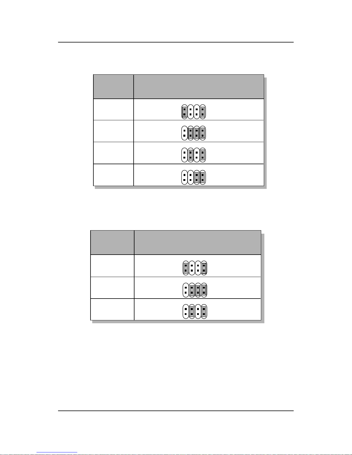
CHAPTER 2 HARDWARE INSTALLATION
2-19
Table 2.2 350 ~ 450MHz Intel® Pentium® II processor
400MHz
450MHz
350MHz
CPU
Type
SW1
b. 100MHz CPU Bus Frequency
Table 2.1 233 ~ 333MHz Intel® Pentium® II/Celeron
TM
processor
233MHz
266MHz
300MHz
333MHz
CPU
T ype
SW1
a. 66MHz CPU Bus Frequency
123
4
123
4
123
4
123
4
123
4
123
4
123
4
CHAPTER 2 HARDWARE INSTALLATION
2-20
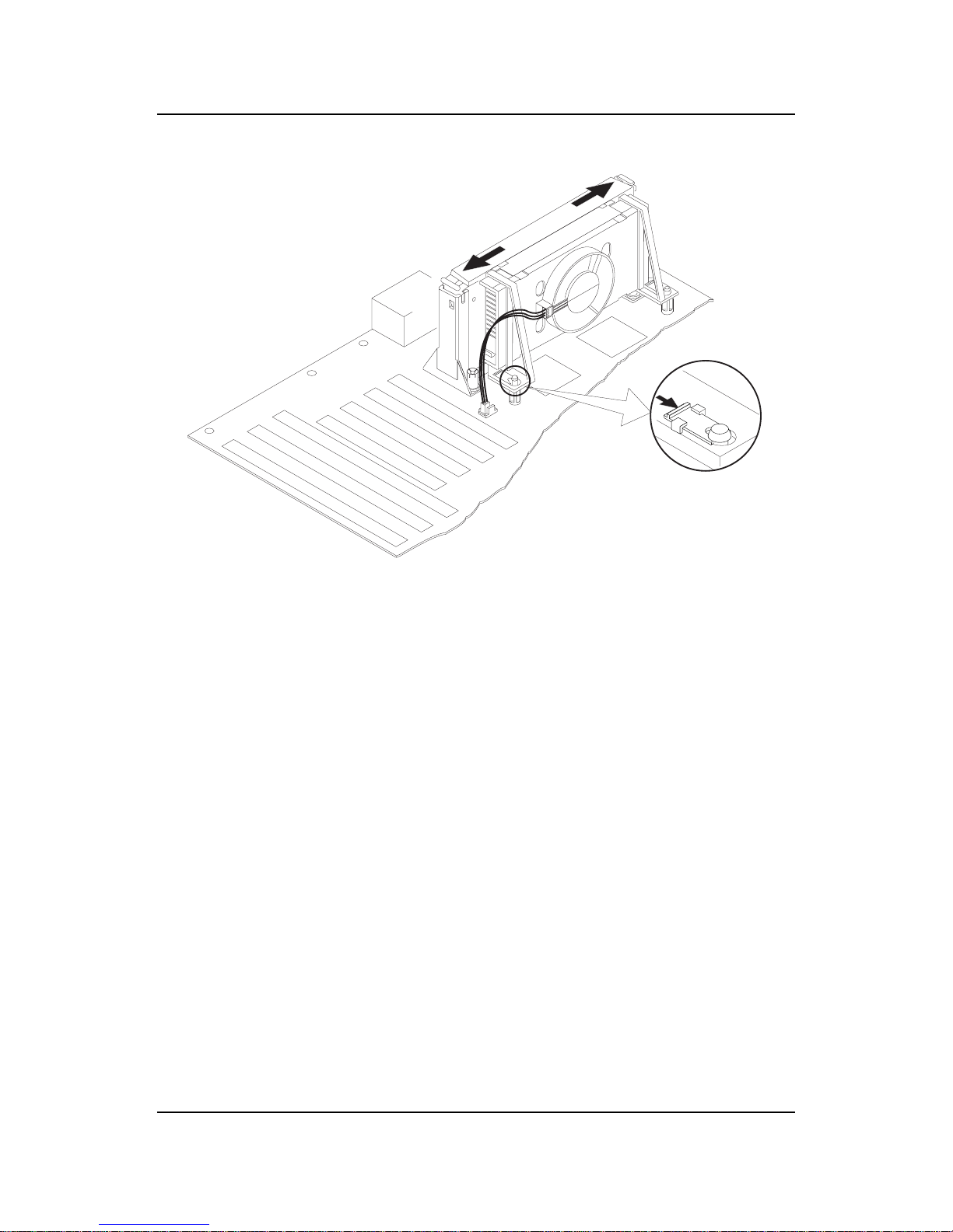
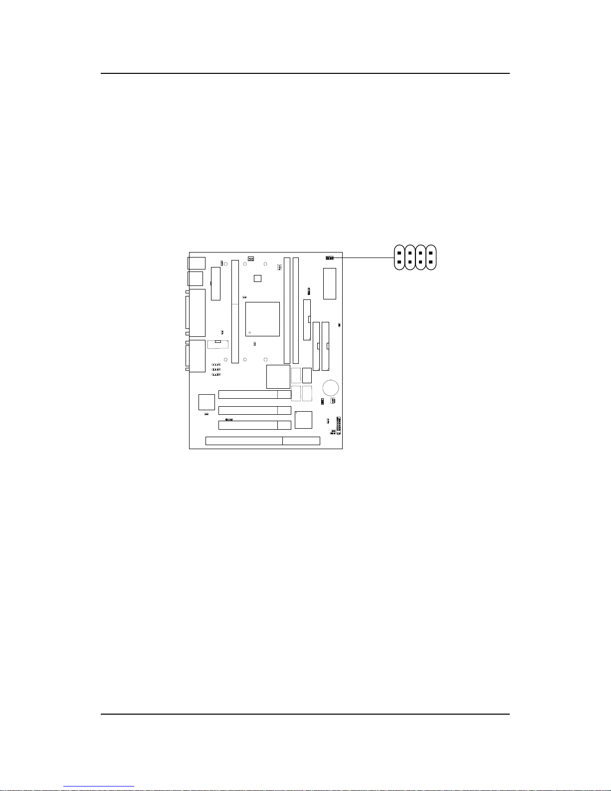
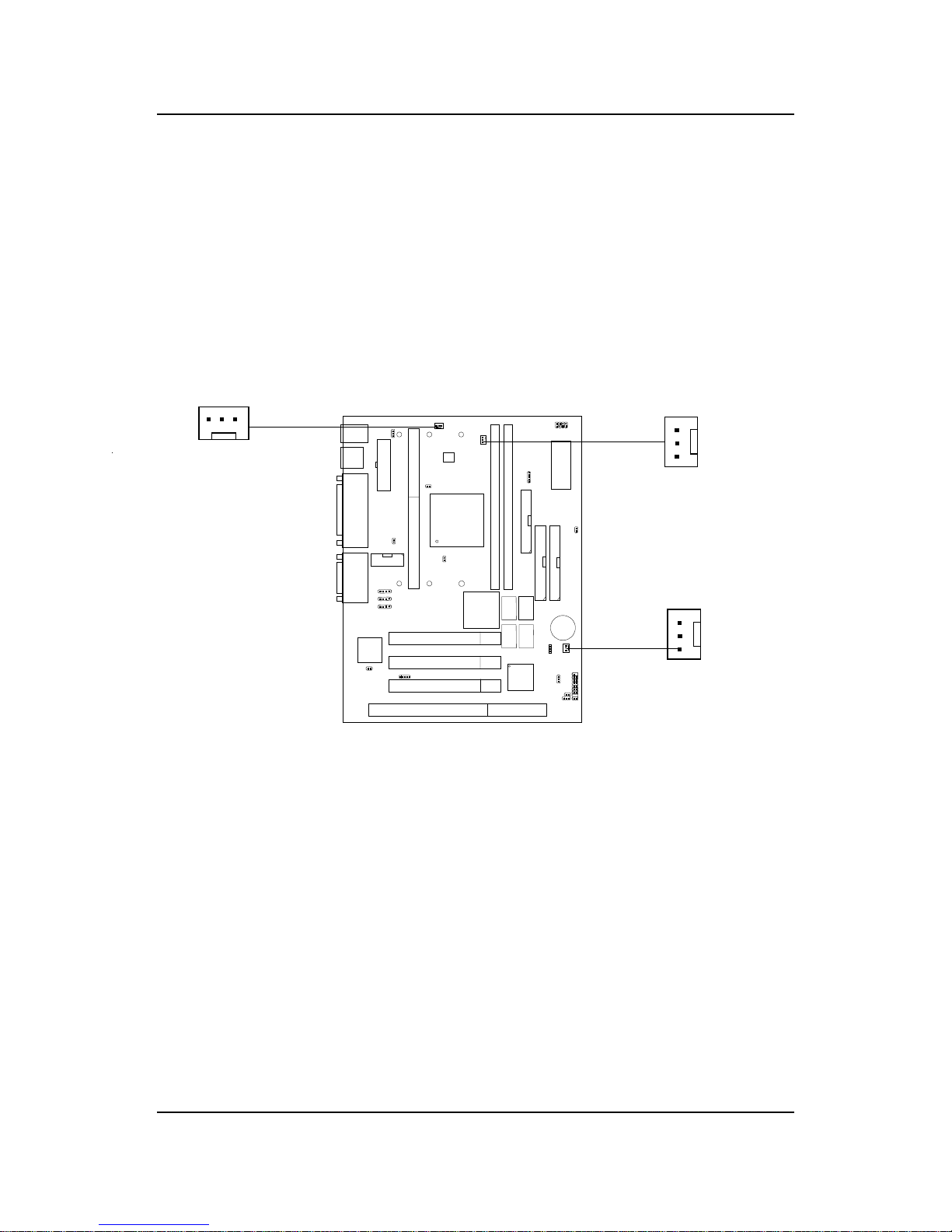
2.1-4 Fan Power Connectors: CPUFAN/PSFAN/SYSFAN
These connectors support system cooling fan with +12V. It supports three
pin head connector. When connecting the wire to the connector, always
take note that the red wire is the positive and should be connected to the
+12V, the black wire is Ground and should be connected to GND. If your
mainboard has System Hardware Monitor chipset on-board, you must use a
specially designed fan with speed sensor to take advantage of this function.
For fans with fan speed sensor, every rotation of the fan will send out 2
pulses. System Hardware Monitor will count and report the fan rotation
speed.
SENSOR
+12V
GND
PSFAN1
SENSOR
+12V
GND
CPUFAN
PSFAN : Power Supply Fan
CPUF AN : Processor Fan
SYSFAN : System(Chassis) Fan
SYSFAN
Note: 1 . Always consult vendor for proper CPU cooling fan.
SENSOR
+12V
GND

CHAPTER 2 HARDWARE INSTALLATION
2-21
2.2 Clear CMOS Jumper: JBAT1
A battery must be used to retain the mainboard configuration in CMOS
RAM. Short 1-2 pins of JBAT1 to store the CMOS data.
Keep Data
Clear Data
1
1
3
3
Note: You can clear CMOS by shorting 2-3 pin, while the system is off .
Then, return to 1-2 pin position. A void clearing the CMOS while
the system is on, it will damage the mainboard. Always unplug
the power cord from the wall socket.
2
2
JBAT1
1
3
CHAPTER 2 HARDWARE INSTALLATION
2-22
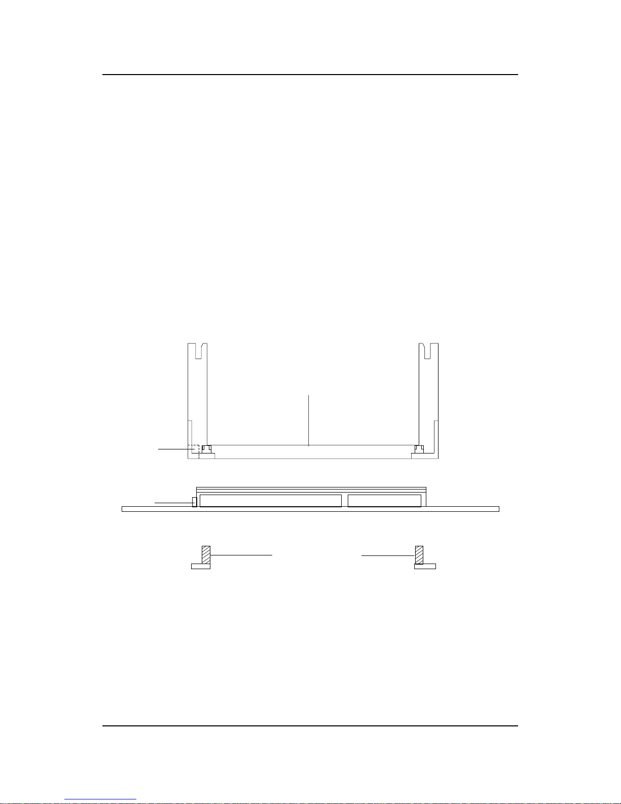
2.3 Memory Installation
2.3-1 Memory Bank Configuration
The mainboard supports a maximum memory size of 256MB (8M x 8) or
512MB (16M x 4) registered DIMM for SDRAM: It provides two 168-pin
unbuffered DIMMs (Double In-Line Memory Module) sockets. It supports
8 MB to 256 Mbytes DIMM memory module.
DIMM1(Bank0 + Bank1)
DIMM2(Bank2+ Bank3)
There are two kinds of DIMM specification supported
by this mainboard: PC100 and PC66. If you use
66MHz CPU Bus Frequency, these two DIMM Specs. is
supported. If you use 100 MHz CPU Bus Frequency,
only PC100 DIMM Specs. is supported.
!
W ARNING!

CHAPTER 2 HARDWARE INSTALLATION
2-23
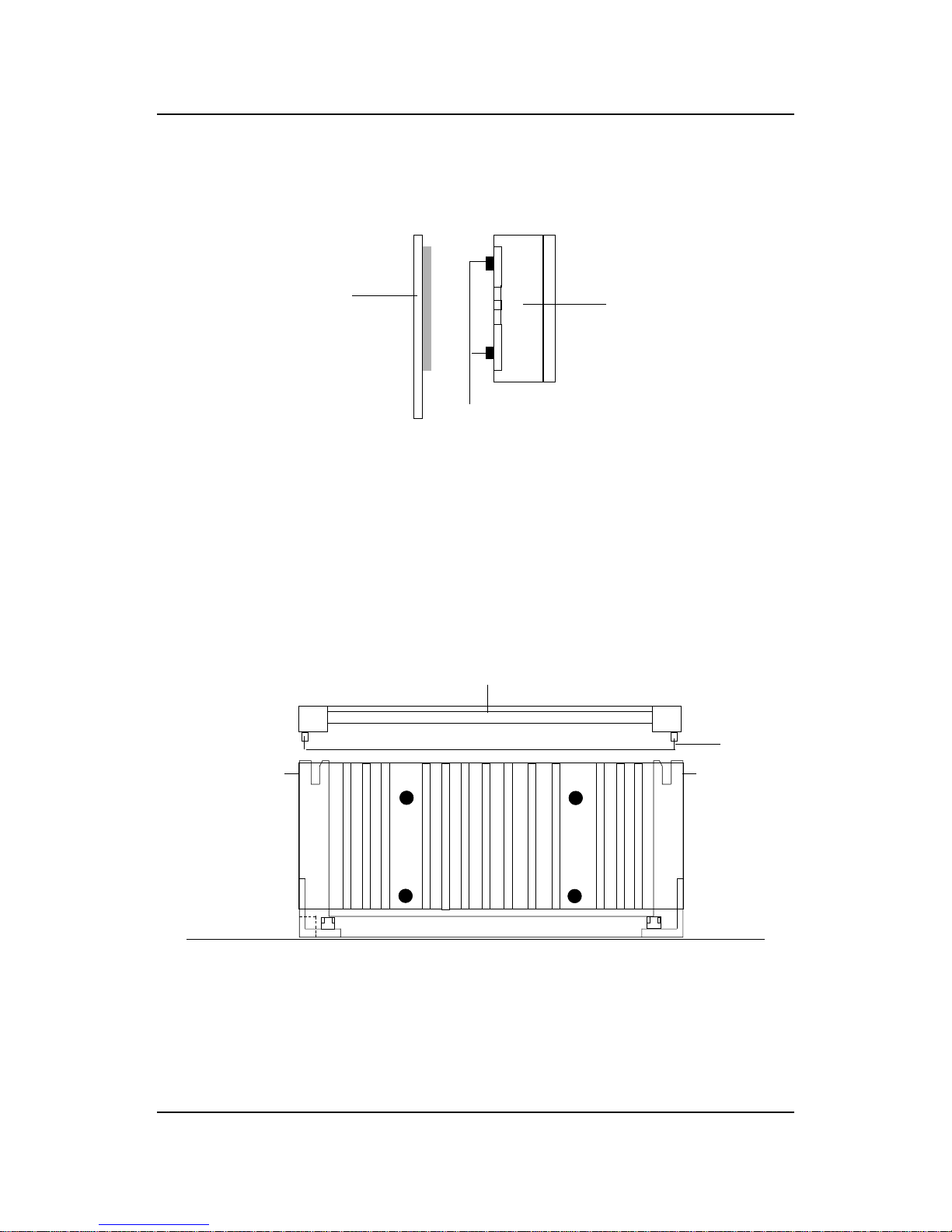
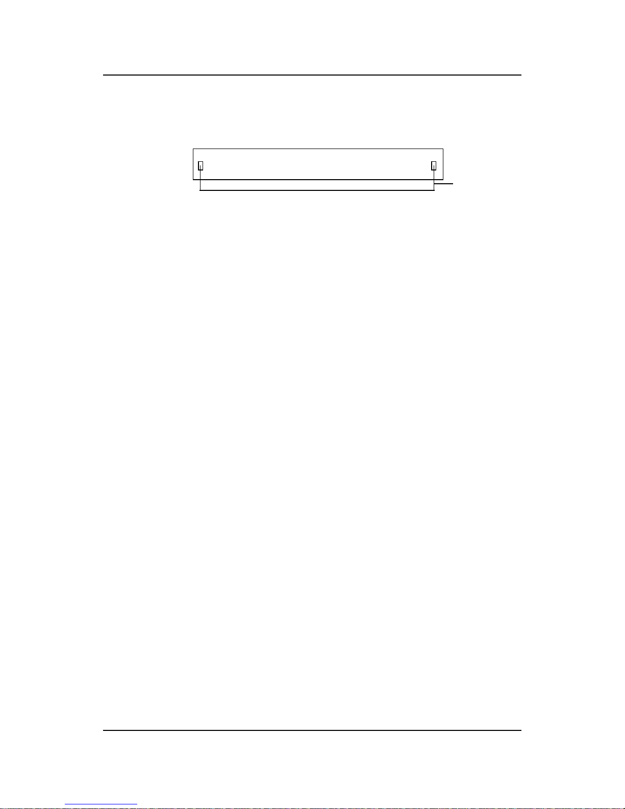
A. How to install a DIMM Module
1. The DIMM slot has a two Notch Key “VOLT and DRAM”, so the
DIMM memory module can only fit in one direction.
2. Insert the DIMM memory module vertically into the DIMM slot.
Then push it in.
3. The plastic clip at the side of the DIMM slot will automatically
close..
Single Sided DIMM
Double Sided DIMM
VOLTDRAM
2.3-2 Memory Installation Procedures
CHAPTER 2 HARDWARE INSTALLATION
2-24
1 . Supports only SDRAM DIMM.
2 . T o operate properly, at least one 168-pin DIMM module must be in-
stalled.
3. This mainboard supports T able Free memory , so memory can be installed
on DIMM1 or DIMM 2 in any order .
4. Supports 3.3 volt DIMM.
5. The DRAM addressing and the size supported by the mainboard is
shown below:
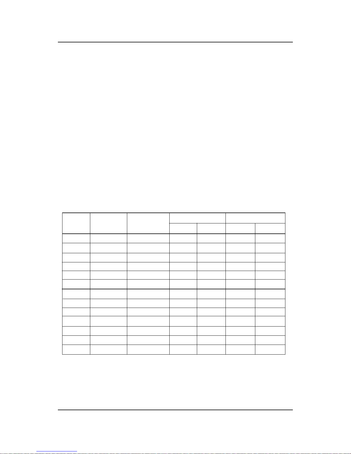
2.3-3 Memory Population Rules
16M 1Mx16 ASYM 11 8 8MBx4 16MBx8
2Mx8 ASYM 11 9 16MBx8 32MBx16
4Mx4 ASYM 11 10 32MB 64MB
64M 2Mx32 ASYM 11 9 32MBx2 64MBx4
2Mx32 ASYM 12 8 16MBx2 32MBx4
4Mx16 ASYM 11 10 32MB 64MB
4Mx16 ASYM 13 8 32MB 64MB
8Mx8 ASYM 13 9 64MB 128MB
16Mx4 ASYM 13 10 128MB 256MB
64M 2Mx32 ASYM 12 8 16MB 32MB
4Mx16 ASYM 13 8 32MB 64MB
8Mx8 ASYM 13 9 64MB 128MB
16Mx4 ASYM 13 10 128MB 256MB
DRAM
Tech.
DRAM
Density &
Width
DRAM
Addressing
Address Size
MB/DIMM
Row
Column
Single
Side(S)
Double
Side(D)
no.
pcs.
no.
pcs.
T able 2.3-1 SDRAM Memory Addressing

CHAPTER 2 HARDWARE INSTALLATION
2-25
2.4 Case Connector: JFP1
The Power Switch, Reset Switch, Power LED, Speaker, Keylock and HDD
LED are all connected to the JFP1 connector block.
JFP1
Power
Switch
Power LED
+
Reset
Switch
HDD
LED
+
Speaker
Buzzer
(short pin)
14
15
Keylock
Dual
Color
LED
Single
Color
LED
 Loading...