

MSI MS-6120 User Manual

CHAPTER 1 INTRODUCTION
1-1
Chapter 1
INTRODUCTION
The ATX BX2 mainboard is a high-performance dual-processor personal
computer mainboard based on the Intel® Pentium® II processor. The Intel
®
Pentium® II processor supports MMXTM(Multimedia Extension) technology .
The mainboard uses the highly integrated Intel® 82440BX chipset to support
the PCI/ISA and Green standards, and to provide the Host/AGP bridge. The
82371EB chipset integrates all system control functions such as ACPI
(Advanced Configuration and Power Interface). The ACPI provides more
Energy Saving Features for the OSPM(OS Direct Power Management)
function. The Intel® 82371EB chipset also improves the IDE transfer rate by
supporting Ultra DMA/33 IDE that transfers data at the rate of 33MB/s.
The mainboard also supports the System Hardware Monitor Controller as an
optional function. This function includes: CPU /power supply/chassis fan
revolution detect, CPU/system voltage monitor, system temperature monitor ,
and chassis intrusion detect(optional).

CHAPTER 1 INTRODUCTION
1-2
1.1 Mainboard Features
CPU
l T wo Slot 1 for Intel
®
Pentium® II processor.
l Supports FSB 66MHz for 233MHz, 266MHz, 300MHz, 333MHz and higher .
FSB 100MHz for 350MHz, 400MHz, 450MHz, 500MHz and higher
Chipset
l Intel
®
82440BX AGP chipset.
Clock Generator
l 66.6MHz/100MHz clocks are supported.
Main Memory
l Supports eight memory banks using four 168-pin unbuffered DIMM
sockets.
l Supports a maximum memory size of 1GB for Registered SDRAM and
512MB for Unbuffered SDRAM.
l Supports ECC(1- bit Error Code Correct) and EC(Multiple-Bit Error Detect)
function.
Slots
l One AGP(Accelerated Graphics Port) slot.
- AGP specification compliant
- AGP 66/133MHz 3.3v device support
l Five 32-bit PCI Bus slots (provides four PCI Master slots and one PCI
Slave slot) and two 16-bit ISA bus slots (one shared slot)
l Supports 3.3v/5v PCI bus Interface.
On-Board IDE
l An IDE controller on the Intel
®
82371EB PCI Chipset provides IDE HDD/
CD-ROM with PIO, Bus Master and Ultra DMA/33 operation modes.
l Can connect up to four IDE devices.

CHAPTER 1 INTRODUCTION
1-3
On-Board Dual Channel Ultra Wide SCSI
l Adaptec
®
7895 Dual Channel Ultra Wide chipset.
On-Board Peripherals
l On-Board Peripherals include:
- 1 floppy port supports 2 FDD with 360K, 720K, 1.2M, 1.44M and
2.88Mbytes.
- 2 serial ports (COMA + COMB) or 1 serial port and 1 IrDA port.
- 1 parallel port supports SPP/EPP/ECP mode
- 2 USB ports
Switching V oltage Regulator
l On-board switching mode DC-DC Step Down Regulator .
l Conforms to Intel VRM ver 8.1 specifications.
l Over-Voltage and Over-Current protection.
BIOS
l The mainboard BIOS provides “Plug & Play” BIOS which detects the
peripheral devices and expansion cards of the board automatically.
l The mainboard provides a Desktop Management Interface(DMI) function
which records your mainboard specifications.
Dimension
l ATX form factor: 30cm(L) x 25cm(W) x 6 layers PCB
Mounting
l 9 mounting holes.
System Hardware Monitor (optional)
l CPU/Power Supply/Chassis Fan Revolution Detect
l CPU Fan Control (the fan will automatically stop when the system enters
suspend mode)
l System Voltage Detect
l CPU Overheat W arning.
l Display Actual Current Voltage

CHAPTER 1 INTRODUCTION
1-4
1.2 Mainboard Layout
MS-6120
DIMM 1
Top: mouse
Bottom:
keyboard
Top: Port 1
USB
Top: LPT
Bottom:
COM A
COM B
DIMM 2
DIMM 3
DIMM 4
ISA SLOT 1
PCI SLOT 4
PCI SLOT 3
PCI SLOT 2
PCI SLOT 1
SLOT 1
ISA SLOT 2
FDC
BATT
+
IDE2
IDE1
Hardware
Monitor
ATX
Power Supply
BIOS
FW82371EB
JFP1
JIPWR
CSFAN1
CFAN1
IR1
PSFAN1
FW82443BX
AGP
Bottom:
Port 2
CFAN2
PCI SLOT 5
SLOT 1
I/O
APIC
16-bit Ultra Wide SCSI CH1
JWLED1
JBAT1
JMDM1
JWOL1
JSOUND
JSOR1
JSOR2
JRMS1
JRMS2
JSM1
SW1
JGS1
JGL1
16-bit Ultra Wide SCSI CH2
8-bit Ultra SCSI CH2
Adaptec
7895
JDSCSI
5
1
10
6
1
3
4
6
1
6
1
1
10
9
18

CHAPTER 2 HARDWARE INSTALLATION
2-1
Chapter 2
HARDWARE INSTALLATION
2.1 Central Processing Unit: CPU
The mainboard operates with Intel® Pentium® II processor with MMX
TM
technology . The mainboard uses a CPU Slot called Slot 1 for easy CPU
installation and a DIP switch (SW1) to set the proper speed for the CPU.
The CPU should always have a Heat Sink and a cooling fan attached to
prevent overheating.

CHAPTER 2 HARDWARE INSTALLATION
2-2
2.1-1 CPU Installation Procedures
A. OEM Pentium
®
II processor Installation Procedures
There are two kinds of Pentium® II processor that is currently used: the
OEM Pentium® II processor and the Boxed Pentium® II processor. OEM
Pentium® II processor has no Heat Sink, Fan and Heat Sink Support, while
the Boxed Pentium® II processor is provided with Heat Sink w/ fan and Heat
Sink Support.
Required Things:
Pentium® II processor - Processor .
*Retention Mechanism(RM) - Plastic Guide that holds the S.E.C. Catridge
in the Slot 1 connector.
*Retention Mechanism Attach Mount(RMAM) - Bolt/Bridge assemblies
inserted up through the bottom of the
motherboard. RM secures to RMAM ( 2
RMAM required per RM ).
*Heat Sink Support Base (HSSBASE) - Plastic support bar mounted to
the mainboard under the ATX heatsink.
(One leg is always bigger than the other one)
Processor
Lock
Retention
Mechanism
Pentium® II
Processor
Heat Sink
W/Fan
Notch Hole
Heat Sink
Support Base
Heat Sink
Support Pin
Heat Sink
Support
Top Bar

CHAPTER 2 HARDWARE INSTALLATION
2-3
*Heat Sink Support Pin (HSSPIN) - Plastic pins inserted through the
HSSBASE to secure it to the mainboard (2
required per Assembly).
*Heat Sink Support T op Bar (HSSTOP) - Plastic bar that clips onto the
HSSBASE through the fins on the ATX
heatsink.
**Heat Sink w/ fan - Heat Sink that can be attached to the Pentium® II
processor with metal clip.
Note: * Provided by MSI mainboard.
** Provided by Special request.
RM
HSSPIN
HSSTOP
HSSBASE
RMAM
CHAPTER 2 HARDWARE INSTALLATION
2-4
SLOT1
Retention
Mechanism
ê
ê
Key
êê
Retention
Mechanism
Attach Mount
Notch
Key
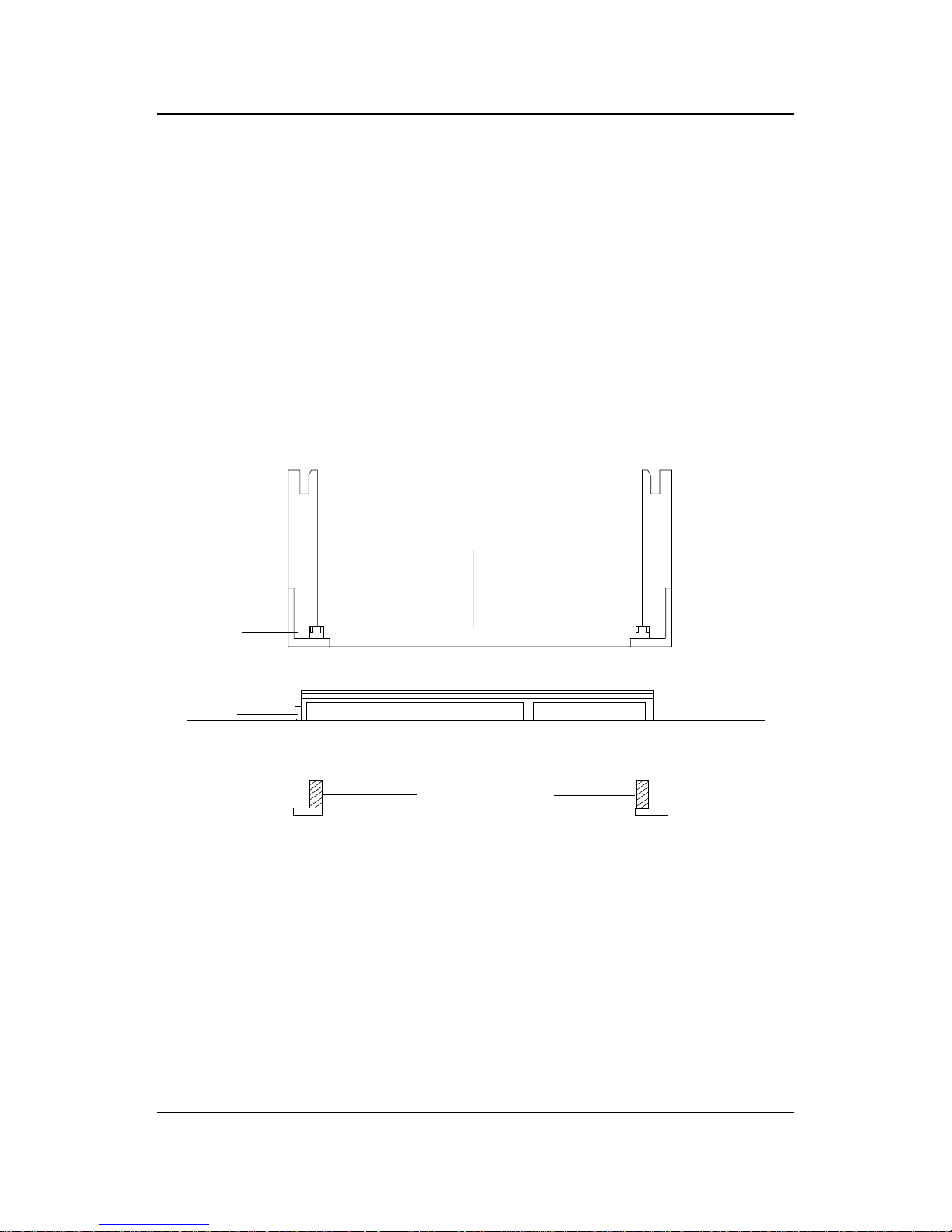
Step 1: Insert the Retention Mechanism Attach Mount at the bottom
of the mainboard.
Step 2: Install the Retention Mechanism.
Look for the key on Slot 1, and match it with the Notch Key on the
Retention Mechanism for proper direction. Then, attach the
Retention Mechanism to the Retention Mechanism Attach Mount.
Use a Screwdriver to secure the Retention Mechanism.

CHAPTER 2 HARDWARE INSTALLATION
2-5
Step 3: Install the Heat Sink Support Base.
Look for the T wo holes across Slot 1, and match it with the Two legs
of the Heat Sink Support Base for the proper direction. T ake note
that one hole/leg is bigger than the other. The Four top pins of the
Heat Sink Support Base should also be oriented towards Slot 1.
Push the Heat Sink Support Base onto the mainboard, until you hear
a click sound. Check for a perfect fit.
Step 4: Install the Heat Sink Support Pin.
Push the Heat Sink Support Pins onto the two holes of the Heat Sink
Support Base. Check for a perfect fit. These pins are used to secure
the Heat Sink Support Base.
Heat Sink
Support Base
Heat Sink
Support Pin
Leg
pins
CHAPTER 2 HARDWARE INSTALLATION
2-6
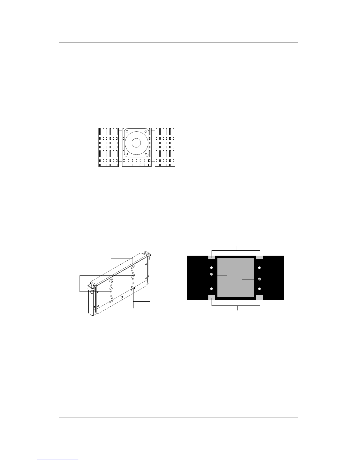
Step 5: Install the Heat Sink with Fan to the Processor .
Push down the metal clips, so that they are in line with the back of
the Heat Sink. Be careful, so as not detach the metal clips from the
Heat Sink.
In case the metal clips are detached from the Heat Sink, re-attach
them. Look for the arrow on the metal clip. This arrow should be
pointing down and aligned with the Heat Sink Support Base Holder.
Attach the Heat Sink to the processor.
- Look at the back of the Heat Sink and take note of the 2 secure
posts. Insert these 2 Secure posts to the 2 secure holes on the
back of the processor.
- Align the ears of the metal clips with the clip holders on the back of
the processor. Use a screw driver to push the metal clips onto the
clip holders. Check for a perfect fit.
Pentium® II processor (Back)
â
The arrow
should be
pointing
down.
Metal Clips
Heat Sink w/ Fan
Metal Clips Ear
Metal Clips Ear
Secure
Posts
Heat Sink w/ Fan(Back)
Heat Sink
Base Holder
Secure
holes
Clip Holder
Clip Holder

CHAPTER 2 HARDWARE INSTALLATION
2-7
Step 6: Install the Processor .
Unlock the Processor by pushing in the Processor Locks.
Insert the Processor like inserting a PCI or an ISA card.
Step 7: Lock the Processor Locks.
Secure the CPU by pulling the Processor Locks out.
è
ç
ç
è
CHAPTER 2 HARDWARE INSTALLATION
2-8
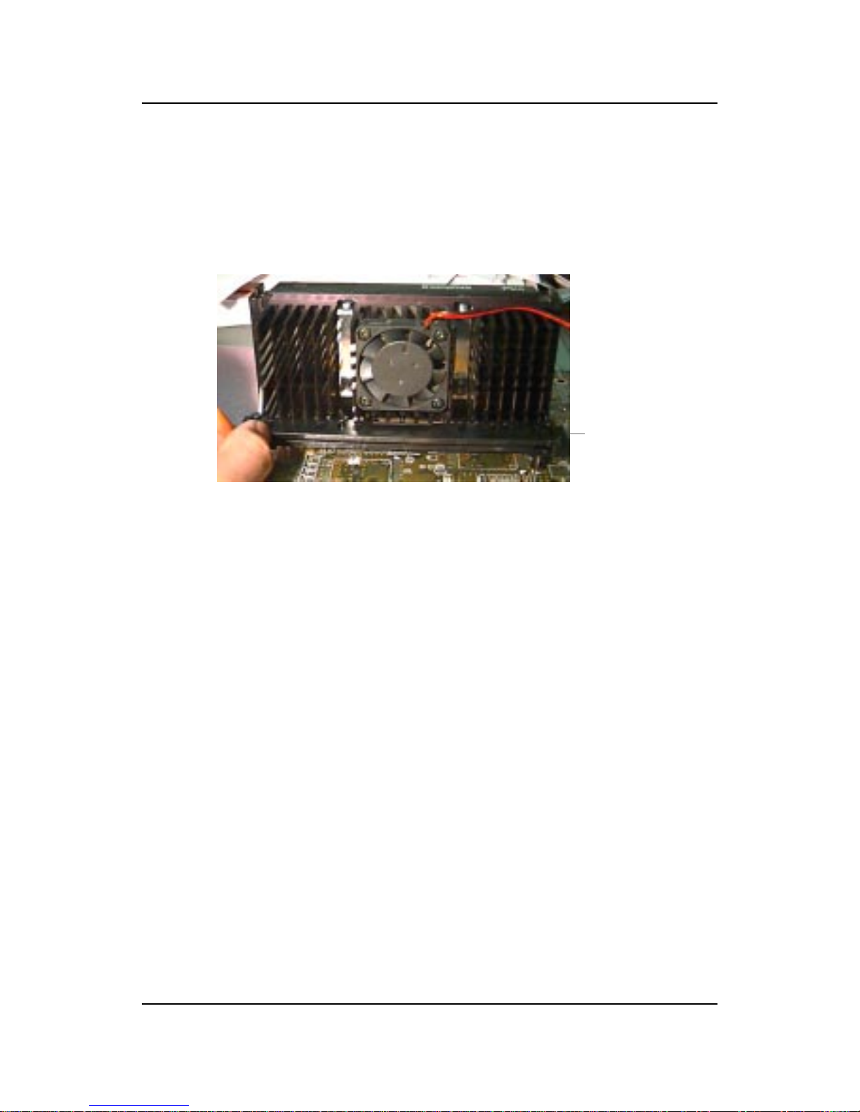
Step 8: Install the Heat Sink Support T op Bar .
Push the Heat Sink Support T op Bar to the Heat Sink Support Base,
Until you hear a “click” sound. Check for a perfect fit.
The installation is now complete.
Heatsink
Support Top
Bar
CHAPTER 2 HARDWARE INSTALLATION
2-9
B. Boxed Pentium® II processor Installation Procedures
The Boxed Pentium® II processor has a built- in Fan and Heat Sink. It also
has a Heat Sink Support. So if you’re going to use the Boxed processor, all
you need is the Retention Mechanism.
SLOT1
Retention
Mechanism
ê
ê
Key
êê
Retention
Mechanism
Attach Mount
Notch
Key
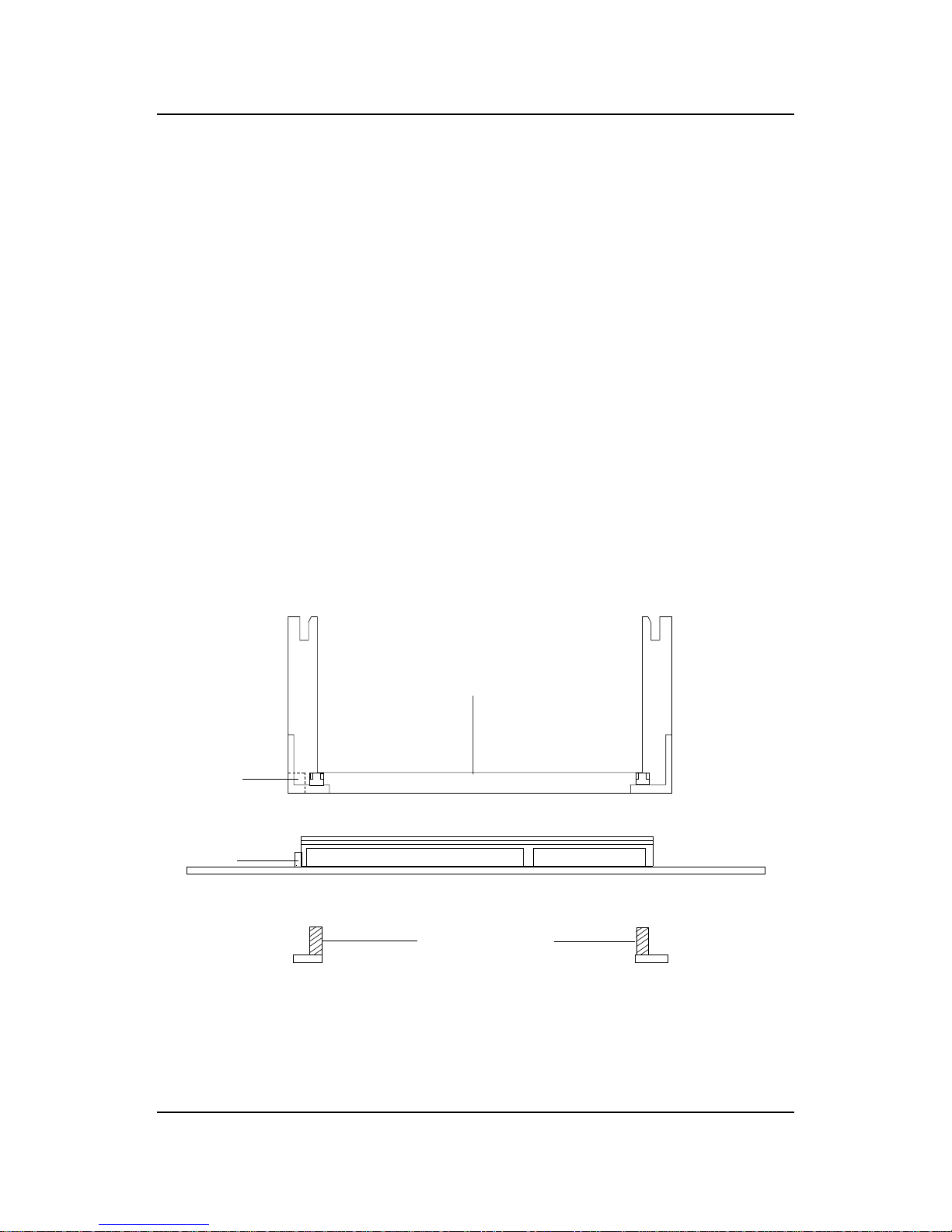
Step 1: Insert the Retention Mechanism Attach Mount at the bottom
of the mainboard.
Step 2: Install the Retention Mechanism.
Look for the key on Slot 1, and match it with the Notch Key on the
Retention Mechanism for proper direction. Then, attach the
Retention Mechanism to the Retention Mechanism Attach Mount.
Use a Screwdriver to secure the Retention Mechanism.
CHAPTER 2 HARDWARE INSTALLATION
2-10
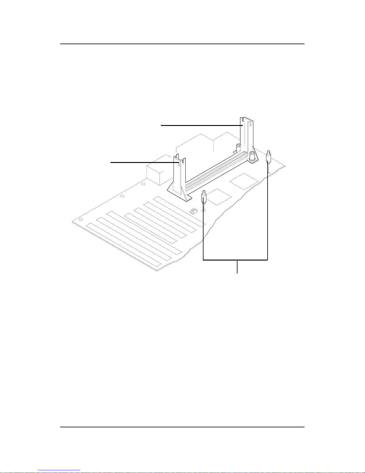
Step 3: Install the Heat Sink Support Base.
Look for the 2 holes across Slot 1, and match it with the 2 Heat Sink
Support Base. Take note that one hole/base is bigger than the other.
Push the Heat Sink Support Base onto the mainboard, until you hear
a click sound. Check for a perfect fit.
PC-3742
Retention
Mechanism
Notch
Hole
Heat Sink
Support Base

CHAPTER 2 HARDWARE INSTALLATION
2-11
PC-3743
Heat Sink
Support Lock
Intel® Boxed
PentiumTM II
Processor
Step 4: Install the Heat Sink Support.
Attach the 2 Heat Sink Supports to the sides of the Processor. These
Heat Sink Supports will fit in any direction, so be sure that the Heat
Sink Support Locks are oriented outwards for the proper direction.
Heat Sink
Support
 Loading...