

Page 1

Preface
Z87-G41 PC Mate
H87-G41 PC Mate
B85-G41 PC Mate
ZH87-G41 PC Mate
Motherboard
G52-78501X2
Page 2

Preface
Copyright Notice
The material in this document is the intellectual property of MICRO-STAR
INTERNATIONAL. We take every care in the preparation of this document, but no
guarantee is given as to the correctness of its contents. Our products are under
continual improvement and we reserve the right to make changes without notice.
Trademarks
All trademarks in this manual are properties of their respective owners.
MSI® is registered trademark of Micro-Star Int’l Co.,Ltd.
■
NVIDIA® is registered trademark of NVIDIA Corporation.
■
ATI® is registered trademark of AMD Corporation.
■
AMD® is registered trademarks of AMD Corporation.
■
Intel® is registered trademarks of Intel Corporation.
■
Windows® is registered trademarks of Microsoft Corporation.
■
AMI® is registered trademark of American Megatrends Inc.
■
Award® is a registered trademark of Phoenix Technologies Ltd.
■
Sound Blaster® is registered trademark of Creative Technology Ltd.
■
Realtek® is registered trademark of Realtek Semiconductor Corporation.
■
JMicron® is registered trademark of JMicron Technology Corporation.
■
Netware® is registered trademark of Novell, Inc.
■
Lucid® is trademark of LucidLogix Technologies, Ltd.
■
VIA® is registered trademark of VIA Technologies, Inc.
■
ASMedia® is registered trademark of ASMedia Technology Inc.
■
iPad, iPhone, and iPod are trademarks of Apple Inc.
■
Qualcomm Atheros and Killer are trademarks of Qualcomm Atheros Inc.
■
Revision History
Revision Revision History Date
V1.0 First release 2013/04
iiPreface
Page 3
Smartphone Application
MSI+ is a smart web gadget that works as a shopping navigator and
provides specs comparison for IT buyers. With a simple tap of the
smartphone, you'll eciently locate your ideal products from a wide
variety of choices and, if product details are required, you may easily
download user manuals within minutes. Better yet, the power calculator
provides accurate estimates of power unit capacity for DIY users.
Technical Support
If a problem arises with your system and no solution can be obtained from the user’s
manual, please contact your place of purchase or local distributor. Alternatively,
please try the following help resources for further guidance.
Preface
Visit the MSI website for technical guide, BIOS
updates, driver updates, and other information:
http://www.msi.com/service/download/
Contact our technical sta at:
http://support.msi.com
iii Preface
Page 4

Preface
Safety Instructions
Always read the safety instructions carefully.
■
Keep this User’s Manual for future reference.
■
Keep this equipment away from humidity.
■
Lay this equipment on a reliable at surface before setting it up.
■
The openings on the enclosure are for air convection hence protects the equipment
■
from overheating. DO NOT COVER THE OPENINGS.
Make sure the voltage of the power source is at 110/220V before connecting the
■
equipment to the power inlet.
Place the power cord such a way that people can not step on it. Do not place
■
anything over the power cord.
Always Unplug the Power Cord before inserting any add-on card or module.
■
All cautions and warnings on the equipment should be noted.
■
Never pour any liquid into the opening that can cause damage or cause electrical
■
shock.
If any of the following situations arises, get the equipment checked by service
■
personnel:
The power cord or plug is damaged.
◯
Liquid has penetrated into the equipment.
◯
The equipment has been exposed to moisture.
◯
The equipment does not work well or you can not get it work according to
◯
User’s Manual.
The equipment has been dropped and damaged.
◯
The equipment has obvious sign of breakage.
◯
DO NOT LEAVE THIS EQUIPMENT IN AN ENVIRONMENT ABOVE 60oC (140oF),
■
IT MAY DAMAGE THE EQUIPMENT.
ivPreface
Page 5
FCC-B Radio Frequency Interference Statement
This equipment has been tested and found to comply with the limits for a Class B
digital device, pursuant to Part 15 of the FCC Rules. These limits are designed to
provide reasonable protection against harmful interference in a residential installation.
This equipment generates, uses and can radiate radio frequency energy and, if not
installed and used in accordance with the instructions, may cause harmful interference
to radio communications. However, there is no guarantee that interference will not
occur in a particular installation. If this equipment does cause harmful interference to
radio or television reception, which can be determined by turning the equipment o
and on, the user is encouraged to try to correct the interference by one or more of the
measures listed below.
Reorient or relocate the receiving antenna.
◯
Increase the separation between the equipment and receiver.
◯
Connect the equipment into an outlet on a circuit dierent from that to which
◯
the receiver is connected.
Consult the dealer or an experienced radio/television technician for help.
◯
Notice 1
The changes or modications not expressly approved by the party responsible for
compliance could void the user’s authority to operate the equipment.
Notice 2
Shielded interface cables and A.C. power cord, if any, must be used in order to comply
with the emission limits.
VOIR LA NOTICE D’INSTALLATION AVANT DE RACCORDER AU RESEAU.
Micro-Star International
MS-7850
Preface
This device complies with Part 15 of the FCC Rules. Operation is subject to the
following two conditions:
this device may not cause harmful interference, and
1)
this device must accept any interference received, including interference that may
2)
cause undesired operation.
CE Conformity
Hereby, Micro-Star International CO., LTD declares that this device is
in compliance with the essential safety requirements and other relevant
provisions set out in the European Directive.
v Preface
Page 6
Preface
Radiation Exposure Statement
This equipment complies with FCC radiation exposure limits set forth for an
uncontrolled environment. This equipment and its antenna should be installed and
operated with minimum distance 20 cm between the radiator and your body. This
equipment and its antenna must not be co-located or operating in conjunction with any
other antenna or transmitter.
European Community Compliance Statement
The equipment complies with the RF Exposure Requirement 1999/519/EC, Council
Recommendation of 12 July 1999 on the limitation of exposure of the general public
to electromagnetic elds (0–300GHz). This wireless device complies with the R&TTE
Directive.
Taiwan Wireless Statements
無線設備警告聲明
經型式認證合格之低功率射頻電機,非經許可,公司、商號或使用者均不得擅自變更頻
率、加大功率或變更原設計之特性及功能。
低功率射頻電機之使用不得影響飛航安全及干擾合法通信;經發現有干擾現象時,應立
即停用,並改善至無干擾時方得繼續使用。前項合法通信,指依電信法規定作業之無線
電通信。低功率射頻電機須忍受合法通信或工業、科學及醫療用電波輻射性電機設備之
干擾。
警告使用者:這是甲類資訊產品,在居住的環境中使用時,可能會造成無線電干擾,在
這種情況下,使用者會被要求採取某些適當的對策。
Japan VCCI Class B Statement
クラス B 情報技術装置
この装置は、情報技術装置等電波障害自主規制協議会(VCCI)の基準に基づくクラ
スB情報技術装置です。この装置が家庭内でラジオやテレビジョン受信機に近接して
使われると、受信障害を引き起こすことがあります。取扱説明書にしたがって正しい
取り扱いをしてください。
Korea Warning Statements
당해 무선설비는 운용중 전파혼신 가능성이 있음
viPreface
Page 7
Battery Information
European Union:
Batteries, battery packs, and accumulators should not be disposed of
as unsorted household waste. Please use the public collection system
to return, recycle, or treat them in compliance with the local regulations.
Taiwan:
For better environmental protection, waste batteries should be collected
separately for recycling or special disposal.
廢電池請回收
California, USA:
The button cell battery may contain perchlorate material and requires
special handling when recycled or disposed of in California.
For further information please visit:
http://www.dtsc.ca.gov/hazardouswaste/perchlorate/
CAUTION: There is a risk of explosion, if battery is incorrectly replaced.
Replace only with the same or equivalent type recommended by the manufacturer.
Chemical Substances Information
In compliance with chemical substances regulations, such as the EU REACH
Regulation (Regulation EC No. 1907/2006 of the European Parliament and the
Council), MSI provides the information of chemical substances in products at:
http://www.msi.com/html/popup/csr/evmtprtt_pcm.html
Preface
vii Preface
Page 8
WEEE (Waste Electrical and Electronic Equipment) Statement
Preface
ENGLISH
To protect the global environment and as an environmentalist, MSI must
remind you that...
Under the European Union (“EU”) Directive on Waste Electrical and
Electronic Equipment, Directive 2002/96/EC, which takes eect on August
13, 2005, products of “electrical and electronic equipment” cannot be
discarded as municipal wastes anymore, and manufacturers of covered
electronic equipment will be obligated to take back such products at the end of their
useful life. MSI will comply with the product take back requirements at the end of life
of MSI-branded products that are sold into the EU. You can return these products to
local collection points.
DEUTSCH
Hinweis von MSI zur Erhaltung und Schutz unserer Umwelt
Gemäß der Richtlinie 2002/96/EG über Elektro- und Elektronik-Altgeräte dürfen
Elektro- und Elektronik-Altgeräte nicht mehr als kommunale Abfälle entsorgt werden.
MSI hat europaweit verschiedene Sammel- und Recyclingunternehmen beauftragt,
die in die Europäische Union in Verkehr gebrachten Produkte, am Ende seines
Lebenszyklus zurückzunehmen. Bitte entsorgen Sie dieses Produkt zum gegebenen
Zeitpunkt ausschliesslich an einer lokalen Altgerätesammelstelle in Ihrer Nähe.
FRANÇAIS
En tant qu’écologiste et an de protéger l’environnement, MSI tient à rappeler ceci...
Au sujet de la directive européenne (EU) relative aux déchets des équipement
électriques et électroniques, directive 2002/96/EC, prenant eet le 13 août 2005,
que les produits électriques et électroniques ne peuvent être déposés dans les
décharges ou tout simplement mis à la poubelle. Les fabricants de ces équipements
seront obligés de récupérer certains produits en n de vie. MSI prendra en compte
cette exigence relative au retour des produits en n de vie au sein de la communauté
européenne. Par conséquent vous pouvez retourner localement ces matériels dans
les points de collecte.
РУССКИЙ
Компания MSI предпринимает активные действия по защите окружающей среды,
поэтому напоминаем вам, что....
В соответствии с директивой Европейского Союза (ЕС) по предотвращению
загрязнения окружающей среды использованным электрическим и электронным
оборудованием (директива WEEE 2002/96/EC), вступающей в силу 13
августа 2005 года, изделия, относящиеся к электрическому и электронному
оборудованию, не могут рассматриваться как бытовой мусор, поэтому
производители вышеперечисленного электронного оборудования обязаны
принимать его для переработки по окончании срока службы. MSI обязуется
соблюдать требования по приему продукции, проданной под маркой MSI на
территории EC, в переработку по окончании срока службы. Вы можете вернуть
эти изделия в специализированные пункты приема.
viiiPreface
Page 9

ESPAÑOL
MSI como empresa comprometida con la protección del medio ambiente, recomienda:
Bajo la directiva 2002/96/EC de la Unión Europea en materia de desechos y/o
equipos electrónicos, con fecha de rigor desde el 13 de agosto de 2005, los productos
clasicados como “eléctricos y equipos electrónicos” no pueden ser depositados en
los contenedores habituales de su municipio, los fabricantes de equipos electrónicos,
están obligados a hacerse cargo de dichos productos al termino de su período de
vida. MSI estará comprometido con los términos de recogida de sus productos
vendidos en la Unión Europea al nal de su periodo de vida. Usted debe depositar
estos productos en el punto limpio establecido por el ayuntamiento de su localidad o
entregar a una empresa autorizada para la recogida de estos residuos.
NEDERLANDS
Om het milieu te beschermen, wil MSI u eraan herinneren dat….
De richtlijn van de Europese Unie (EU) met betrekking tot Vervuiling van Electrische
en Electronische producten (2002/96/EC), die op 13 Augustus 2005 in zal gaan
kunnen niet meer beschouwd worden als vervuiling. Fabrikanten van dit soort
producten worden verplicht om producten retour te nemen aan het eind van hun
levenscyclus. MSI zal overeenkomstig de richtlijn handelen voor de producten
die de merknaam MSI dragen en verkocht zijn in de EU. Deze goederen kunnen
geretourneerd worden op lokale inzamelingspunten.
SRPSKI
Da bi zaštitili prirodnu sredinu, i kao preduzeće koje vodi računa o okolini i prirodnoj
sredini, MSI mora da vas podesti da…
Po Direktivi Evropske unije (“EU”) o odbačenoj ekektronskoj i električnoj opremi,
Direktiva 2002/96/EC, koja stupa na snagu od 13. Avgusta 2005, proizvodi koji
spadaju pod “elektronsku i električnu opremu” ne mogu više biti odbačeni kao običan
otpad i proizvođači ove opreme biće prinuđeni da uzmu natrag ove proizvode na kraju
njihovog uobičajenog veka trajanja. MSI će poštovati zahtev o preuzimanju ovakvih
proizvoda kojima je istekao vek trajanja, koji imaju MSI oznaku i koji su prodati u EU.
Ove proizvode možete vratiti na lokalnim mestima za prikupljanje.
Preface
POLSKI
Aby chronić nasze środowisko naturalne oraz jako rma dbająca o ekologię, MSI
przypomina, że...
Zgodnie z Dyrektywą Unii Europejskiej (“UE”) dotyczącą odpadów produktów
elektrycznych i elektronicznych (Dyrektywa 2002/96/EC), która wchodzi w życie 13
sierpnia 2005, tzw. “produkty oraz wyposażenie elektryczne i elektroniczne “ nie
mogą być traktowane jako śmieci komunalne, tak więc producenci tych produktów
będą zobowiązani do odbierania ich w momencie gdy produkt jest wycofywany z
użycia. MSI wypełni wymagania UE, przyjmując produkty (sprzedawane na terenie
Unii Europejskiej) wycofywane z użycia. Produkty MSI będzie można zwracać w
wyznaczonych punktach zbiorczych.
ix Preface
Page 10

Preface
TÜRKÇE
Çevreci özelliğiyle bilinen MSI dünyada çevreyi korumak için hatırlatır:
Avrupa Birliği (AB) Kararnamesi Elektrik ve Elektronik Malzeme Atığı, 2002/96/EC
Kararnamesi altında 13 Ağustos 2005 tarihinden itibaren geçerli olmak üzere,
elektrikli ve elektronik malzemeler diğer atıklar gibi çöpe atılamayacak ve bu elektonik
cihazların üreticileri, cihazların kullanım süreleri bittikten sonra ürünleri geri toplamakla
yükümlü olacaktır. Avrupa Birliği’ne satılan MSI markalı ürünlerin kullanım süreleri
bittiğinde MSI ürünlerin geri alınması isteği ile işbirliği içerisinde olacaktır. Ürünlerinizi
yerel toplama noktalarına bırakabilirsiniz.
ČESKY
Záleží nám na ochraně životního prostředí - společnost MSI upozorňuje...
Podle směrnice Evropské unie (“EU”) o likvidaci elektrických a elektronických výrobků
2002/96/EC platné od 13. srpna 2005 je zakázáno likvidovat “elektrické a elektronické
výrobky” v běžném komunálním odpadu a výrobci elektronických výrobků, na které
se tato směrnice vztahuje, budou povinni odebírat takové výrobky zpět po skončení
jejich životnosti. Společnost MSI splní požadavky na odebírání výrobků značky
MSI, prodávaných v zemích EU, po skončení jejich životnosti. Tyto výrobky můžete
odevzdat v místních sběrnách.
MAGYAR
Annak érdekében, hogy környezetünket megvédjük, illetve környezetvédőként fellépve
az MSI emlékezteti Önt, hogy ...
Az Európai Unió („EU”) 2005. augusztus 13-án hatályba lépő, az elektromos
és elektronikus berendezések hulladékairól szóló 2002/96/EK irányelve szerint
az elektromos és elektronikus berendezések többé nem kezelhetőek lakossági
hulladékként, és az ilyen elektronikus berendezések gyártói kötelessé válnak az
ilyen termékek visszavételére azok hasznos élettartama végén. Az MSI betartja a
termékvisszavétellel kapcsolatos követelményeket az MSI márkanév alatt az EU-n
belül értékesített termékek esetében, azok élettartamának végén. Az ilyen termékeket
a legközelebbi gyűjtőhelyre viheti.
ITALIANO
Per proteggere l’ambiente, MSI, da sempre amica della natura, ti ricorda che….
In base alla Direttiva dell’Unione Europea (EU) sullo Smaltimento dei Materiali Elettrici
ed Elettronici, Direttiva 2002/96/EC in vigore dal 13 Agosto 2005, prodotti appartenenti
alla categoria dei Materiali Elettrici ed Elettronici non possono più essere eliminati
come riuti municipali: i produttori di detti materiali saranno obbligati a ritirare ogni
prodotto alla ne del suo ciclo di vita. MSI si adeguerà a tale Direttiva ritirando tutti i
prodotti marchiati MSI che sono stati venduti all’interno dell’Unione Europea alla ne
del loro ciclo di vita. È possibile portare i prodotti nel più vicino punto di raccolta
xPreface
Page 11
CONTENTS
▍
English ...................................................................................................... En-1
Motherboard Specications ................................................................................En-2
Connectors Quick Guide ....................................................................................En-5
Back Panel Quick Guide ....................................................................................En-7
CPU (Central Processing Unit) ..........................................................................En-9
Memory ............................................................................................................En-13
Mounting Screw Holes .....................................................................................En-14
Power Supply ...................................................................................................En-15
Expansion Slots ...............................................................................................En-16
Video/ Graphics Cards ....................................................................................En-17
Internal Connectors ..........................................................................................En-18
Jumpers ...........................................................................................................En-25
Drivers and Utilities ..........................................................................................En-26
BIOS Setup ......................................................................................................En-27
한국어 ........................................................................................................ Kr-1
메인보드 사양 ..................................................................................................... Kr-2
커넥터 퀵 가이드 ................................................................................................ Kr-5
후면 패널 ............................................................................................................ Kr-7
CPU (중앙 처리 장치) ......................................................................................... Kr-9
메모리 .............................................................................................................. Kr-13
장착 스크류 홀 .................................................................................................. Kr-14
전원 공급 장치 .................................................................................................. Kr-15
확장 슬롯 .......................................................................................................... Kr-16
비디오/ 그래픽 카드 ........................................................................................ Kr-17
내장 커넥터 ...................................................................................................... Kr-18
점퍼 .................................................................................................................. Kr-25
드라이버 및 유틸리티 ....................................................................................... Kr-26
BIOS 설정 ........................................................................................................ Kr-27
日本語 ........................................................................................................Jp-1
マザーボードの仕様 ........................................................................................... Jp-2
コネクタークイックガイド ................................................................................Jp-5
I/Oパネルクイックガイド ..................................................................................Jp-7
CPUに関する注意事項 ....................................................................................... Jp-9
メモリ ..............................................................................................................Jp-13
取付穴 ..............................................................................................................Jp-14
電源 ..................................................................................................................Jp-15
拡張スロット .................................................................................................... Jp-16
ビデオ/ グラフィックスカード .......................................................................Jp-17
内部コネクター ................................................................................................Jp-18
Preface
xi Preface
Page 12

Preface
ジャンパ ........................................................................................................... Jp-25
ドライバーとユーティリティ ..........................................................................Jp-26
BIOSの設定 ...................................................................................................... Jp-27
繁體中文 ....................................................................................................Tc-1
主機板規格 .........................................................................................................Tc-2
接頭快速指南 ......................................................................................................Tc-5
背板快速指南 ......................................................................................................Tc-7
CPU (中央處理器) ..............................................................................................Tc-9
記憶體 ..............................................................................................................Tc-13
裝機孔 ..............................................................................................................Tc-14
電源供應器 .......................................................................................................Tc-15
擴充插槽 ........................................................................................................... Tc-16
顯示卡 .............................................................................................................Tc-17
內建接頭 ........................................................................................................... Tc-18
跳線 ..................................................................................................................Tc-25
驅動程式及工具 ................................................................................................Tc-26
BIOS 設定 ........................................................................................................Tc-27
简体中文 ....................................................................................................Sc-1
主板规格 .............................................................................................................Sc-2
组件快速指南 ......................................................................................................Sc-5
后置面板 .............................................................................................................Sc-7
CPU (中央处理器) ..............................................................................................Sc-9
内存 ..................................................................................................................Sc-13
螺丝孔 ..............................................................................................................Sc-14
电源供电 ...........................................................................................................Sc-15
扩展插槽 ...........................................................................................................Sc-16
视频/ 显卡 .......................................................................................................Sc-17
内部接口 ...........................................................................................................Sc-18
跳线 ..................................................................................................................Sc-25
驱动和实用程序 ................................................................................................Sc-26
BIOS Setup ......................................................................................................Sc-27
Installation/ 설치하기/ インストール/ 安裝/ 安装 ...................................... A-1
CPU ......................................................................................................................A-2
Memory/ 메모리/ メモリ/ 記憶體/ 内存 .................................................................A-4
Motherboard/ 메인보드/ マザーボード/ 主機板/ 主板 ...........................................A-5
Power Connector/ 전원 커넥터/ 電源コネクター/ 電源接頭/ 电源接口 ................A-7
SATA HDD ...........................................................................................................A-9
mSATA SSD ......................................................................................................A-10
Front Panel Connector/ 전면 패널 커넥터/ フロントパネルコネクター/ 面板接頭/ 前
置面板接口 .........................................................................................................A-11
xiiPreface
Page 13

Peripheral Connector/ 주변 커넥터/ 周辺機器のコネクター/ 週邊接頭/ 周边接口 ....
...........................................................................................................................A-12
Graphics Card/ 그래픽 카드/ グラフィックスカード/ ........................................A-13
顯示卡/ 显卡 .......................................................................................................A-13
Preface
xiii Preface
Page 14

Page 15

English
Thank you for choosing the Z87-G41 PC Mate/ H87-G41 PC Mate/ B85-G41
PC Mate Series (MS-7850 v1.X) ATX motherboard. The Z87-G41 PC Mate/
H87-G41 PC Mate/ B85-G41 PC Mate Series motherboards are based on
Intel® Z87/ H87/ B85 chipset for optimal system eciency. Designed to t the
advanced Intel® LGA1150 processor, the Z87-G41 PC Mate/ H87-G41 PC
Mate/ B85-G41 PC Mate Series motherboards deliver a high performance
and professional desktop platform solution.
Page 16
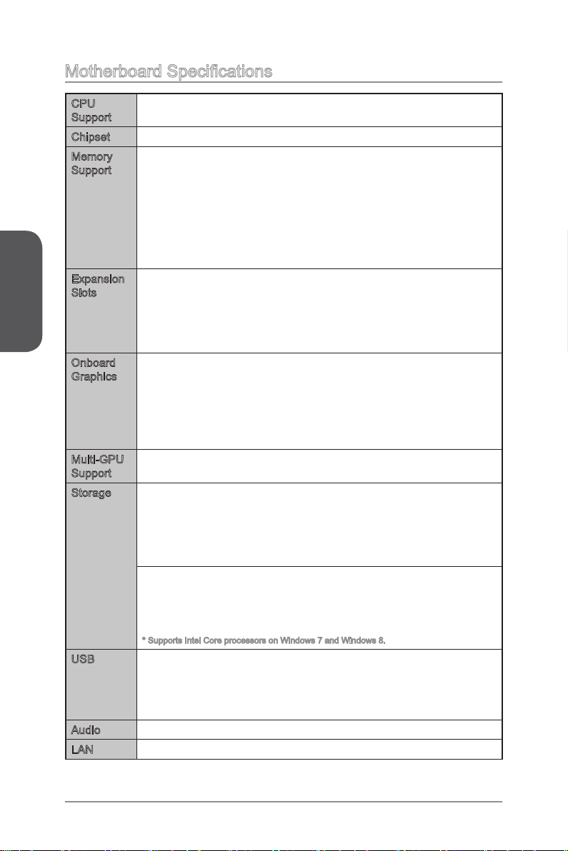
Motherboard Specications
English
CPU
Support
Chipset Intel® Z87/ H87/ B85 Express Chipset■
Memory
Support
Expansion
Slots
Onboard
Graphics
Multi-GPU
Support
Storage Z87-G41 PC Mate/ H87-G41 PC Mate
USB Intel Z87/ H87/ B85 Express Chipset
Audio Realtek® ALC887 Codec■
LAN Realtek® RTL8111G Gigabit LAN controller■
4th Generation Intel® Core™ i7 / Core™ i5 / Core™ i3 / Pentium® /
■
Celeron® processors for LGA 1150 socket
4x DDR3 memory slots supporting up to 32GB
■
Z87-G41 PC Mate supports DDR3 3000(OC)/ 2800(OC)/ 2666(OC)/
■
2600(OC)/ 2400(OC)/ 2200(OC)/ 2133(OC)/ 2000(OC)/ 1866(OC)/
1600/ 1333/ 1066 MHz
H87-G41 PC Mate and B85-G41 PC Mate supports DDR3 1600/
■
1333/ 1066 MHz
Dual channel memory architecture
■
Supports non-ECC, un-buered memory
■
Supports Intel® Extreme Memory Prole (XMP)
■
2x PCIe x16 slots
■
PCI_E2 supports PCIe 3.0
PCI_E4 supports PCIe 2.0
Support x16, x4/x4 modes
-
2x PCIe 2.0 x1 slots
■
2x PCI slots
■
1x VGA port, supporting a maximum resolution of 1920x1200 @
■
60Hz, 24bpp
1x DVI-D port, supporting a maximum resolution of 1920x1200 @
■
60Hz, 24bpp
1x HDMI port, supporting a maximum resolution of
■
4096x2160@24Hz, 24bpp/ 2560x1600@60Hz, 24bpp/
1920x1080@60Hz, 36bpp
Supports AMD CrossFireTM Technology■
■
Intel Z87/ H87 Express Chipset
6x SATA 6Gb/s ports (SATA1~6)
Supports RAID 0, RAID1, RAID 5 and RAID 10
Supports Intel Smart Response Technology, Intel Rapid Start
Technology and Intel Smart Connect Technology*
B85-G41 PC Mate
■
Intel B85 Express Chipset
4x SATA 6Gb/s ports (SATA1, SATA2, SATA3, SATA4)
2x SATA 3Gb/s ports (SATA5, SATA6)
Supports Intel Smart Connect Technology*
-
* Supports Intel Core processors on Windows 7 and Windows 8.
■
4x USB 3.0 ports (2 ports on the back panel, 2 ports available
through the internal USB connectors)
8x USB 2.0 ports (4 ports on the back panel, 4 ports available
through the internal USB connectors)
En-2
Page 17
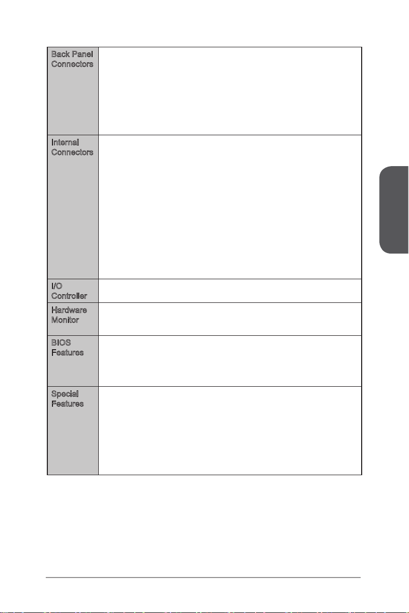
Back Panel
Connectors
Internal
Connectors
I/O
Controller
Hardware
Monitor
BIOS
Features
Special
Features
1x PS/2 mouse port
■
1x PS/2 keyboard port
■
4x USB 2.0 ports
■
2x USB 3.0 ports
■
1x HDMI port
■
1x VGA port
■
1x DVI-D port
■
1x LAN (RJ45) port
■
3x audio jacks
■
1x 24-pin ATX main power connector
■
1x 8-pin ATX 12V power connector
■
6x SATA connectors
■
2x USB 2.0 connectors (supports additional 4 USB 2.0 ports)
■
1x USB 3.0 connector (supports additional 2 USB 3.0 ports)
■
2x 4-pin CPU fan connectors
■
1x 4-pin system fan connector
■
2x 3-pin system fan connectors
■
1x Clear CMOS jumper
■
1x Front panel audio connector
■
2x System panel connectors
■
1x Chassis Intrusion connector
■
1x TPM module connector
■
1x Serial port connector
■
1x Parallel Port connector
■
NUVOTON NCT6779 Controller Chip■
CPU/System temperature detection
■
CPU/System fan speed detection
■
CPU/System fan speed control
■
64 Mb ash (for Z87-G41 PC Mate)
■
128 Mb ash (for H87-G41 PC Mate/ B85-G41 PC Mate)
■
UEFI AMI BIOS
■
ACPI 5.0, PnP 1.0a, SM BIOS 2.7, DMI 2.0
■
Multi-language
■
Military Class 4
■
OC Genie 4
■
Click BIOS 4
■
AMD CrossFire
■
Sound Blaster Cinema (for Z87-G41 PC Mate)
■
Clear CMOS Button
■
Total Fan Control
■
Super RAID
■
Command Center
■
English
En-3
Page 18

English
Software Drivers
Form
Factor
■
MSI
■
Command Center
Super Charger
Super RAID
Live Update 5
Fast Boot
-
7-ZIP
■
Intel Extreme Tuning Utility
■
Norton Internet Security Solution
■
Trend Micro SafeSync
■
Sound Blaster Cinema (for Z87-G41 PC Mate)
■
Network genie
■
Small Business Advantage (for H87-G41 PC Mate/ B85-G41 PC
■
Mate)
ATX Form Factor
■
12 in. x 8.7 in. (30.5 cm x 22 cm)
■
For the latest information about CPU, please visit
http://www.msi.com/service/cpu-support/
For more information on compatible components, please visit
http://www.msi.com/service/test-report/
En-4
Page 19
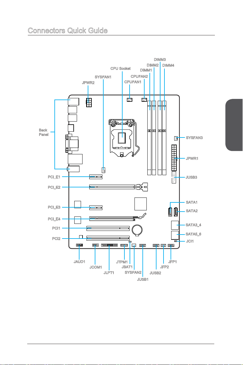
Connectors Quick Guide
SYSFAN1
JPWR2
Back
Panel
CPU Socket
CPUFAN1
DIMM1
CPUFAN2
DIMM2
DIMM3
DIMM4
SYSFAN3
JPWR1
English
PCI_E1
PCI_E2
PCI_E3
PCI_E4
PCI1
PCI2
JAUD1
JCOM1
JLPT1
JTPM1
JBAT1
En-5
SYSFAN2
JUSB3
SATA1
SATA2
SATA3_4
SATA5_6
JCI1
JFP1
JFP2
JUSB2
JUSB1
Page 20

English
Connectors Reference Guide
Port Name Port Type Page
Back Panel CPU & Heatsink Installation En
CPU LGA1150 CPU Socket En-
CPUFAN1~2,SYSFAN1~3 Fan Power Connectors En-1
DIMM1~4 DDR3 Memory Slots En-1
JAUD1 Front Panel Audio Connector En-2
JBAT1 Clear CMOS Jumper En-2
JCI1 Chassis Intrusion Connector En-2
JCOM1 Serial Port Connector En-2
JFP1, JFP2 System Panel Connectors En-2
JLPT1 Parallel Port Connector En-2
JPWR1~2 ATX Power Connectors En-1
JTPM1 TPM Module Connector En-2
JUSB1~2 USB 2.0 Expansion Connectors En-2
JUSB3 USB 3.0 Expansion Connector En-2
PCI_E2,4 PCIe x16 Expansion Slots En-1
PCI_E1,3 PCIe x1 Expansion Slots En-1
SATA1~6 SATA Connectors En-1
-7
9
9
3
2
5
2
3
0
4
5
3
1
1
6
6
8
En-6
Page 21

Back Panel Quick Guide
PS/2 Mouse Port
USB 2.0 Port
PS/2 Keyboard Port
PS/2 Mouse/ Keyboard Port
▶
USB 3.0 Port
VGA Port
HDMI
DVI-D Port
LAN Port
Line-In
Line-Out
Mic
PS/2® mouse/ keyboard DIN connector for a PS/2® mouse/ keyboard.
USB 2.0 Port
▶
The USB 2.0 port is for attaching USB 2.0 devices such as keyboard, mouse, or other
USB 2.0-compatible devices.
USB 3.0 Port
▶
USB 3.0 port is backward-compatible with USB 2.0 devices. It supports data transfer
rate up to 5 Gbit/s (SuperSpeed).
Important
In order to use USB 3.0 devices, you must connect to a USB 3.0 port. If a USB cable
is used, it must be USB 3.0 compliant.
HDMI Port
▶
The High-Denition Multimedia Interface (HDMI) is an all-digital audio-video interface
that is capable of transmitting uncompressed streams. HDMI supports all types of TV
formats, including standard, enhanced, or high-denition video, plus multi-channel
digital audio on a single cable.
VGA Port
▶
The DB15-pin female connector is provided for monitor.
DVI-D Port
▶
The DVI-D (Digital Visual Interface- Digital) connector can be connected to a LCD
monitor, or a CRT monitor with an adapter. To connect a monitor, please refer to the
monitor’s manual for more information.
English
En-7
Page 22
English
Important
This platform supports dual-display and triple-display function.
HDMI+VGA HDMI+DVI VGA+DVI HDMI+VGA+DVI
Extend mode
(Extend the desktop to the second
and third monitor)
Clone mode
(Monitors have the same screen)
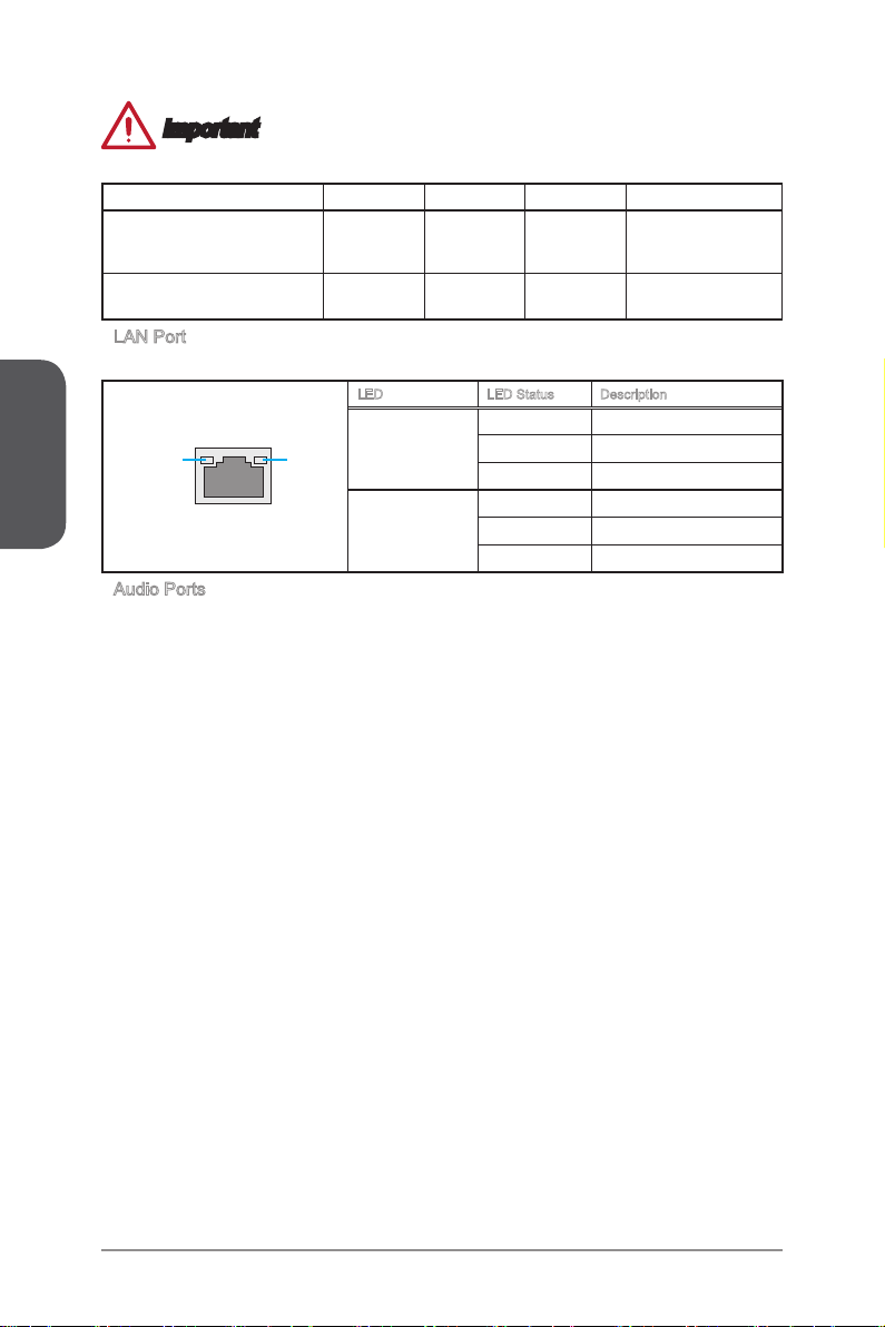
LAN Port
▶
The standard RJ-45 LAN jack is for connecting to a Local Area Network (LAN).
LINK/ACT
LED
Audio Ports
▶
SPEED
LED
These connectors are used for audio devices. The color of the jack refers to the
function of the connector.
Blue-Line in: Used for connecting external audio outputting devices.
■
Green- Line out: Used as a connector for speakers or headphone.
■
Pink- Mic: Used as a connector for a microphone.
■
◯ ◯ ◯ ◯
◯ ◯ ◯ ◯
LED LED Status Description
O No link
Link/ Activity LED
Speed LED
Yellow Linked
Blinking Data activity
O 10 Mbps connection
Green 100 Mbps connection
Orange 1 Gbps connection
En-8
Page 23
CPU (Central Processing Unit)
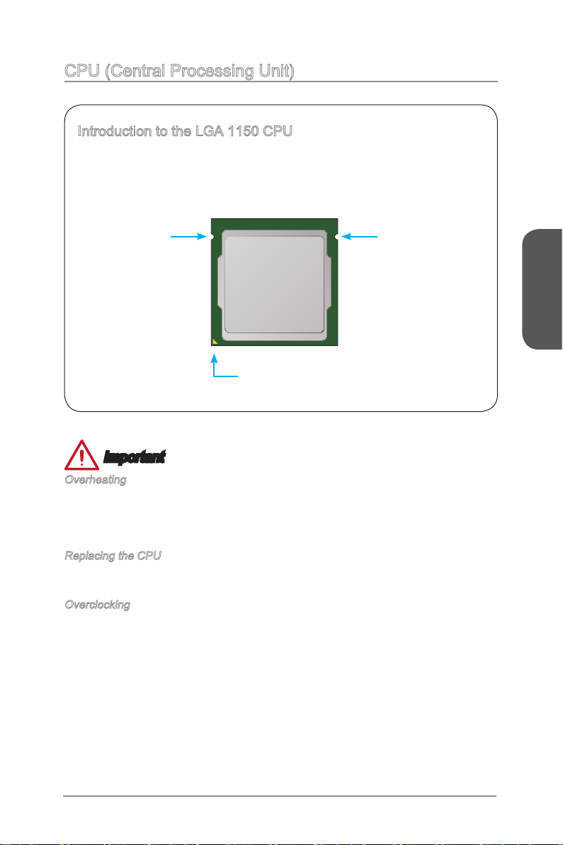
Introduction to the LGA 1150 CPU
The surface of the LGA 1150 CPU has two notches and a golden triangle to
assist in correctly lining up the CPU for motherboard placement. The golden
triangle is the Pin 1 indicator.
Notch
Golden triangle is the Pin 1 indicator
Notch
Important
Overheating
Overheating can seriously damage the CPU and motherboard. Always make sure the
cooling fans work properly to protect the CPU from overheating. Be sure to apply an
even layer of thermal paste (or thermal tape) between the CPU and the heatsink to
enhance heat dissipation.
Replacing the CPU
When replacing the CPU, always turn o the system’s power supply and unplug the
power supply’s power cord to ensure the safety of the CPU.
Overclocking
This motherboard is designed to support overclocking. Before attempting to overclock,
please make sure that all other system components can tolerate overclocking. Any
attempt to operate beyond product specications is not recommend. MSI does not
guarantee the damages or risks caused by inadequate operation beyond product
specications.
English
En-9
Page 24
English
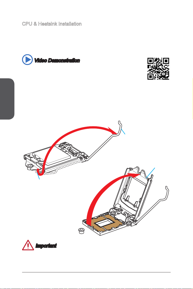
CPU & Heatsink Installation
When installing a CPU, always remember to install a CPU heatsink. A CPU heatsink
is necessary to prevent overheating and maintain system stability. Follow the steps
below to ensure correct CPU and heatsink installation. Wrong installation can damage
both the CPU and the motherboard.
Video Demonstration
Watch the video to learn how to install CPU & heatsink. at the address
below.
http://youtu.be/bf5La099urI
1. Push the load lever down to unclip it and lift to the fully open position.
2. The load plate will automatically lift up as the load lever is pushed to the fully open
position.
Load lever
Load plate
Retention tab
Important
Do not touch the socket contacts or the bottom of the CPU.
En-10
Page 25
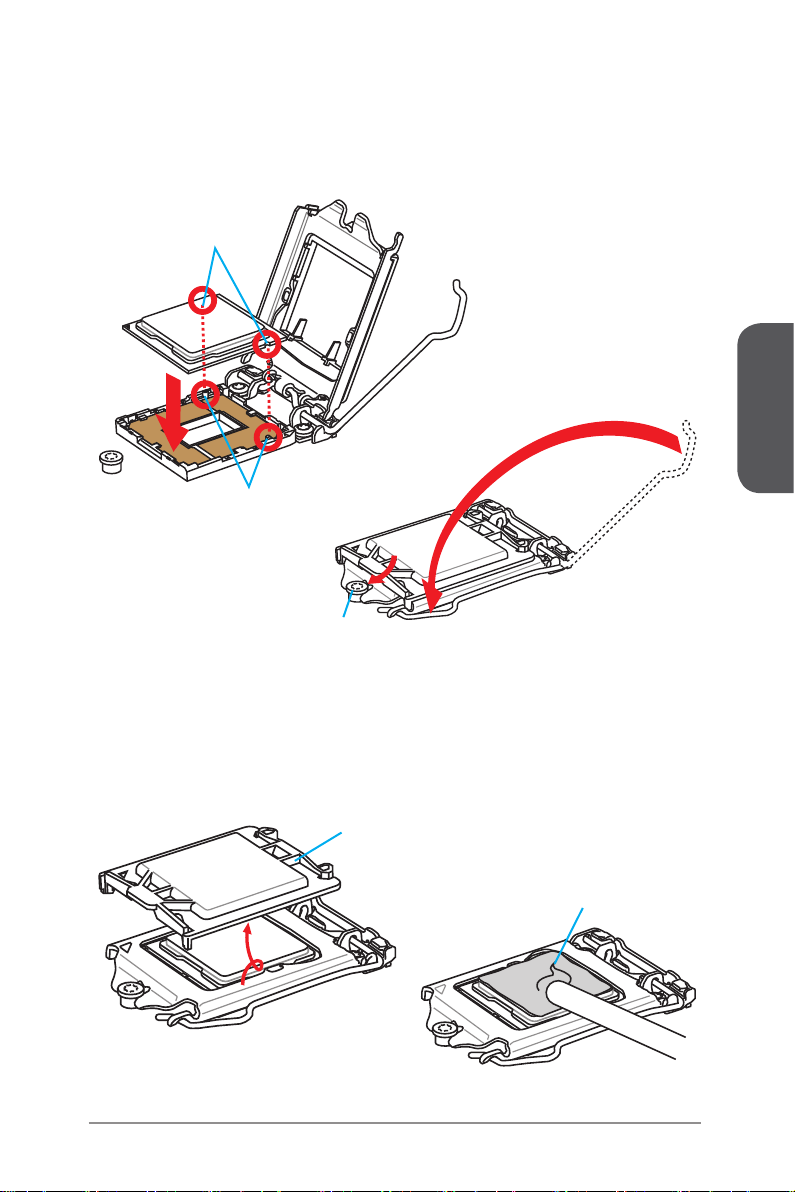
3. Align the notches with the socket alignment keys. Lower the CPU straight down,
without tilting or sliding the CPU in the socket. Inspect the CPU to check if it is
properly seated in the socket.
4. Close and slide the load plate under the retention knob. Close and engage the
load lever.
CPU notches
Alignment Key
Retention knob
English
5. When you press down the load lever the PnP cap will automatically pop up from
the CPU socket. Do not discard the PnP cap. Always replace the PnP cap if the
CPU is removed from the socket.
6. Evenly spread a thin layer of thermal paste (or thermal tape) on the top of the
CPU. This will help in heat dissipation and prevent CPU overheating.
PnP cap
Thermal paste
En-11
Page 26
English
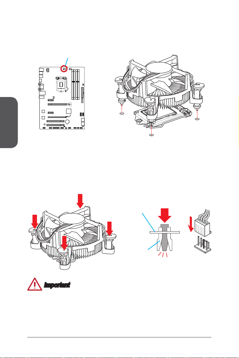
7. Locate the CPU fan connector on the motherboard.
8. Place the heatsink on the motherboard with the fan’s cable facing towards the fan
connector and the fasteners matching the holes on the motherboard.
CPU fan connector
9. Push down the heatsink until the four fasteners get wedged into the holes on
the motherboard. Press the four fasteners down to fasten the heatsink. As each
fastener locks into position a click should be heard.
10. Inspect the motherboard to ensure that the fastener-ends have been properly
locked in place.
11. Finally, attach the CPU fan cable to the CPU fan connector on the motherboard.
Motherboard
Fastener-end
Important
Conrm that the CPU heatsink has formed a tight seal with the CPU before booting
•
your system.
Whenever the CPU is not installed, always protect the CPU socket pins by covering
•
the socket with the plastic cap.
If you purchased a separate CPU and heatsink/ cooler, Please refer to the
•
documentation in the heatsink/ cooler package for more details about installation.
En-12
Page 27
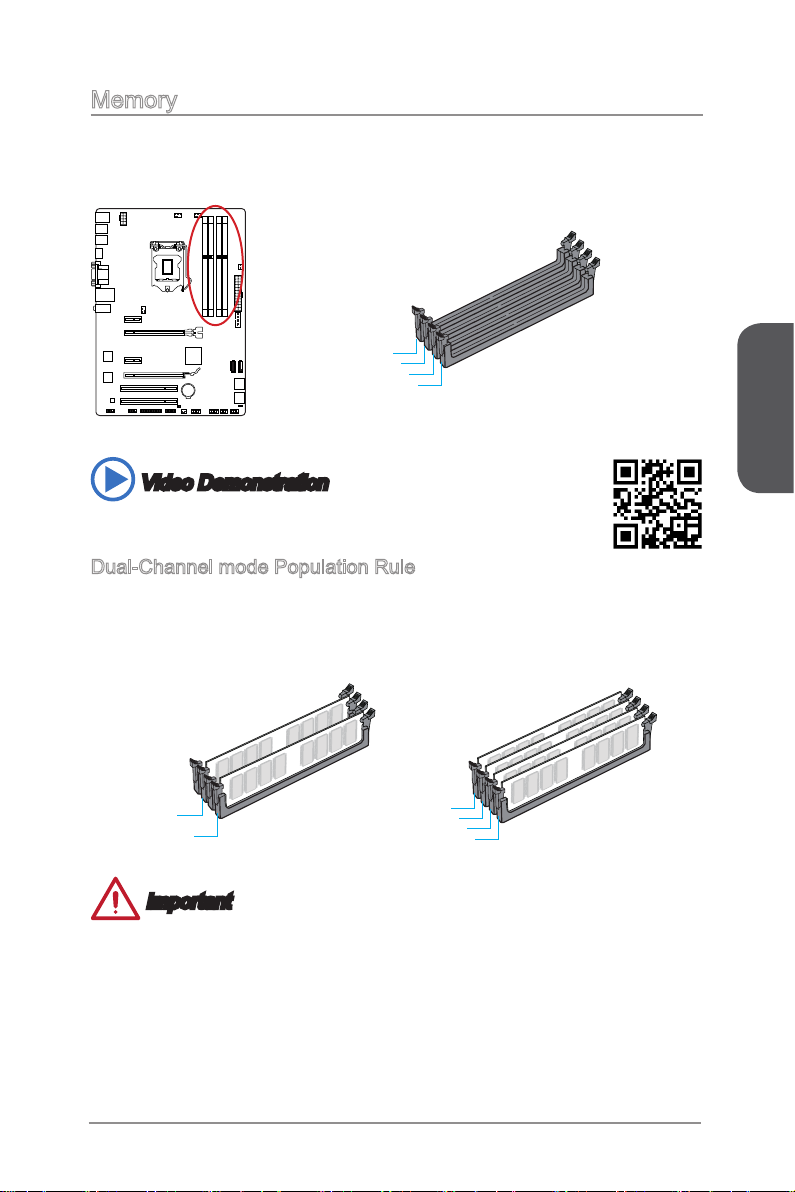
Memory
These DIMM slots are used for installing memory modules. For more information on
compatible components, please visit http://www.msi.com/service/test-report/
DIMM1
DIMM2
DIMM3
DIMM4
Video Demonstration
Watch the video to learn how to install memories at the address below.
http://youtu.be/76yLtJaKlCQ
Dual-Channel mode Population Rule
In Dual-Channel mode, the memory modules can transmit and receive data with two
data bus channels simultaneously. Enabling Dual-Channel mode can enhance system
performance. The following illustrations explain the population rules for Dual-Channel
mode.
English
DIMM2
DIMM4
DIMM1
DIMM2
DIMM3
DIMM4
Important
DDR3 memory modules are not interchangeable with DDR2, and the DDR3
•
standard is not backward compatible. Always install DDR3 memory modules in
DDR3 DIMM slots.
To ensure system stability, memory modules must be of the same type and density
•
in Dual-Channel mode.
Due to chipset resource usage, the system will only detect up to 31+ GB of memory
•
(not full 32 GB) when all DIMM slots have 8GB memory modules installed.
En-13
Page 28
English
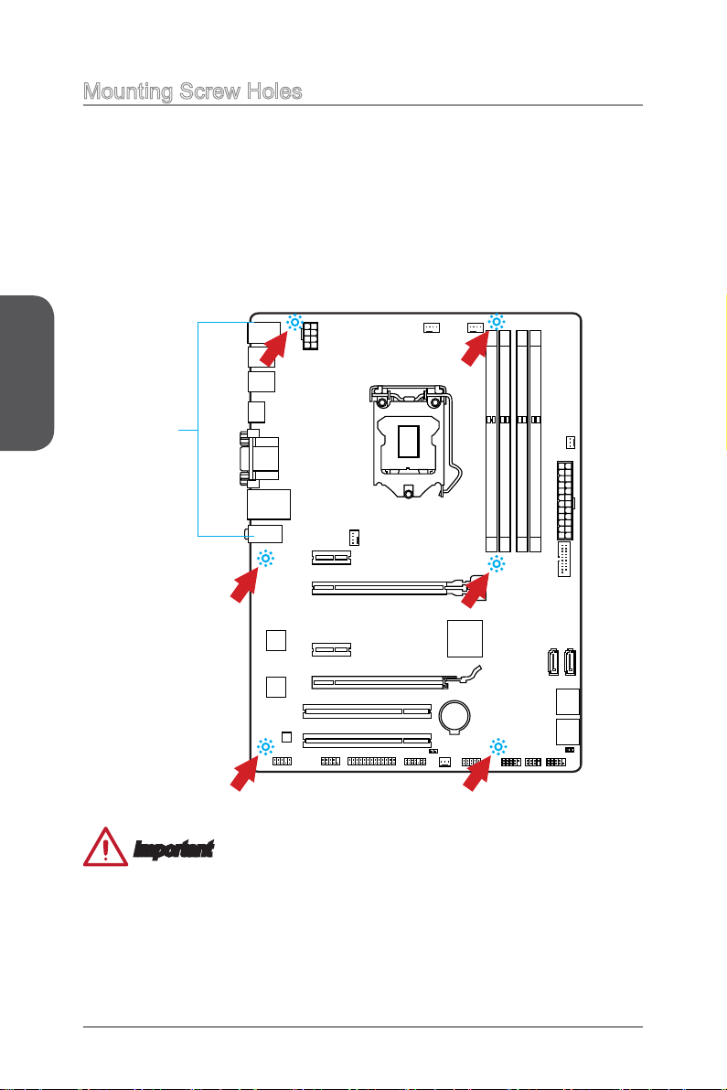
Mounting Screw Holes
When installing the motherboard, rst install the necessary mounting stands required
for an motherboard on the mounting plate in your computer case. If there is an
I/O back plate that came with the computer case, please replace it with the I/O
backplate that came with the motherboard package. The I/O backplate should snap
easily into the computer case without the need for any screws. Align the mounting
plate’s mounting stands with the screw holes on the motherboard and secure the
motherboard with the screws provided with your computer case. The locations of the
screw holes on the motherboard are shown below. For more information, please refer
to the manual that came with the computer case.
The I/O ports should be facing
toward the rear of the computer
case. They should line up with the
holes on the I/O backplate.
Important
Install the motherboard on a at surface free from unnecessary debris.
•
To prevent damage to the motherboard, any contact between the motherboard
•
circuitry and the computer case, except for the mounting stands, is prohibited.
Please make sure there are no loose metal components on the motherboard or
•
within the computer case that may cause a short circuit of the motherboard.
En-14
Page 29
Power Supply
13 .+3 .3
V
1. +3. 3
V
14 .-1 2V
2. +3. 3
V
15 .Gr ou nd
3
.G rou nd
16 .PS -O N
#
4. +5
V
17 .Gr ou nd
5
.G rou nd
18 .Gr ou nd
6. +5
V
19 .Gr ou nd
7
.G rou nd
22 .+5
V
10 .+1 2V
20 .Re s
8. PW
R O
K
23 .+5
V
11
.+ 12V
21 .+5
V
9. 5VS B
24 .Gr ou nd
12 .+3 .3 V
7. +12 V
3.
Gr oun d
5. +12 V
1.
Gr oun d
8. +12 V
4
.G rou nd
6. +12 V
2
.G rou nd
Video Demonstration
Watch the video to learn how to install power supply connectors.
http://youtu.be/gkDYyR_83I4
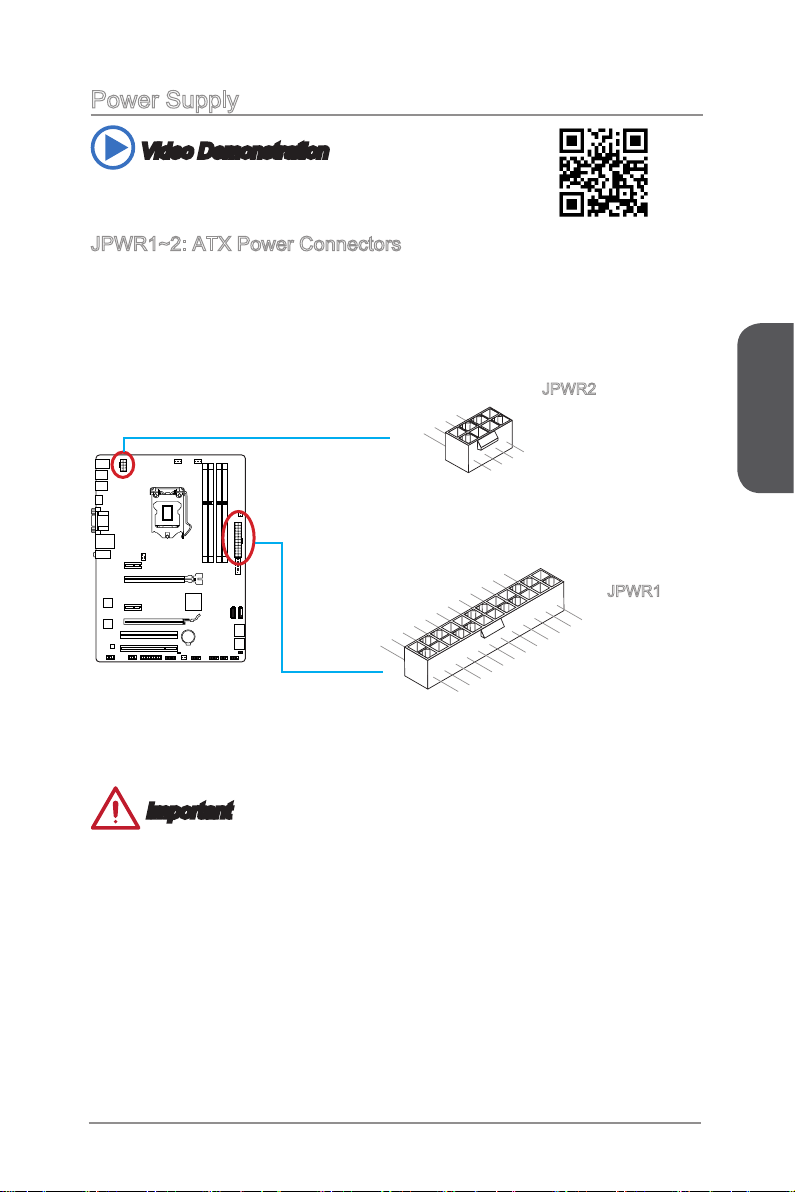
JPWR1~2: ATX Power Connectors
These connectors allow you to connect an ATX power supply. To connect the ATX
power supply, align the power supply cable with the connector and rmly press the
cable into the connector. If done correctly, the clip on the power cable should be
hooked on the motherboard’s power connector.
JPWR2
JPWR1
English
Important
Make sure that all the power cables are securely connected to a proper ATX power
supply to ensure stable operation of the motherboard.
En-15
Page 30
English
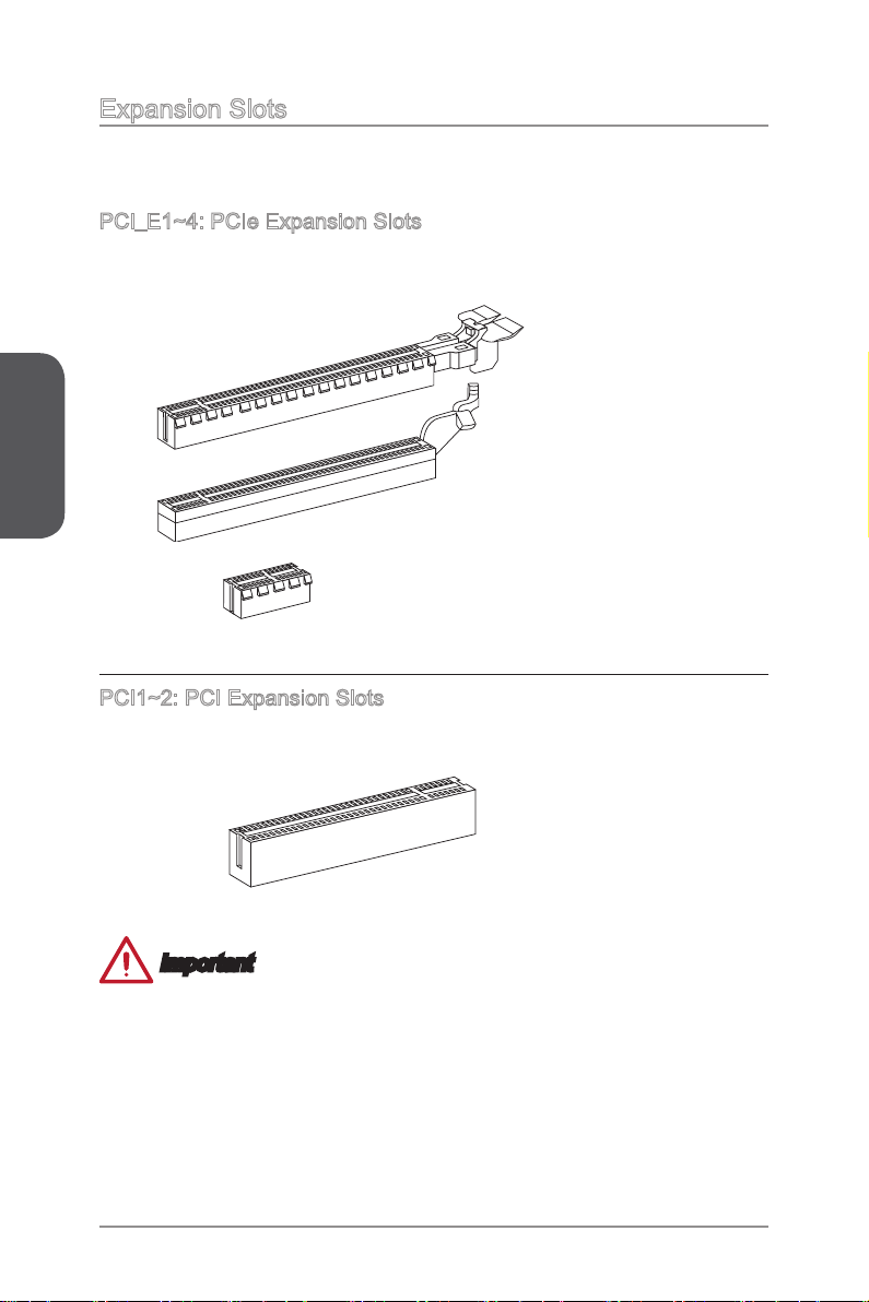
Expansion Slots
This motherboard contains numerous slots for expansion cards, such as discrete
graphics or audio cards.
PCI_E1~4: PCIe Expansion Slots
The PCIe slot supports the PCIe interface expansion card.
PCIe 3.0 x16 Slot
PCIe 2.0 x16 Slot
PCIe 2.0 x1 Slot
PCI1~2: PCI Expansion Slots
The PCI slot supports the PCI interface expansion card..
PCI Slot
Important
When adding or removing expansion cards, always turn o the power supply and
unplug the power supply power cable from the power outlet. Read the expansion
card’s documentation to check for any necessary additional hardware or software
changes.
En-16
Page 31

Video/ Graphics Cards
If available, this motherboard takes advantage of the CPU’s integrate graphics
processor, but discrete video cards can be installed by way of the motherboard’s
expansion slots. Adding on one or more discrete video cards will signicantly boost
the system’s graphics performance. For best compatibility, MSI graphics cards are
recommended.
Video Demonstration
Watch the video to learn how to install a graphics card on PCIe x16 slot
with buttery lock.
http://youtu.be/mG0GZpr9w_A
Single Video Card Installation
Determine what type of expansion slot(s) the video card will use. Locate the
1.
expansion slot(s) on the motherboard. Remove any protective expansion slot
covers from the computer case.
Line up the video card on top of the expansion slot(s) with the display ports facing
2.
out of the computer case. For a single video card installation, using the PCI_E2
slot is recommended.
Push the video card into its expansion slot(s). Depending on the expansion slot(s)
3.
used, there should be clip(s) on the expansion slot(s) that will lock in place.
If needed, screw the edge of the graphics card to the computer case. Some video
4.
cards might require a power cable directly from the power supply.
Please consult your video card’s manual for further instructions regarding driver
5.
installation or other special settings.
English
En-17
Page 32

English
Internal Connectors
SATA1~6: SATA Connectors
This connector is a high-speed SATA interface port. Each connector can connect to
one SATA device. SATA devices include disk drives (HDD), solid state drives (SSD),
and optical drives (CD/ DVD/ Blu-Ray).
Video Demonstration
Watch the video to learn how to Install SATA HDD.
http://youtu.be/RZsMpqxythc
SATA1
SATA2
SATA4
SATA3
SATA6
SATA5
For Z87-G41 PC Mate/ H87-G41 PC Mate
- SATA1~6 (6Gb/s, by Intel® Z87/ H87)
For B85-G41 PC Mate
- SATA1, SATA2, SATA3, SATA4 (6Gb/s, by Intel® B85)
- SATA5, SATA6 (3Gb/s, by Intel® B85)
Important
Many SATA devices also need a power cable from the power supply. Such devices
•
include disk drives (HDD), solid state drives (SSD), and optical drives (CD / DVD /
Blu-Ray). Please refer to the device’s manual for further information.
Many computer cases also require that large SATA devices, such as HDDs, SSDs,
•
and optical drives, be screwed down into the case. Refer to the manual that came
with your computer case or your SATA device for further installation instructions.
Please do not fold the SATA cable at a 90-degree angle. Data loss may result
•
during transmission otherwise.
SATA cables have identical plugs on either sides of the cable. However, it is
•
recommended that the at connector be connected to the motherboard for space
saving purposes.
En-18
Page 33

CPUFAN1~2,SYSFAN1~3: Fan Power Connectors
1
.Ground
2.Speed
C
ontro
l
3.Sens
e
4.NC
1
.Ground
2.+12V
3.Sens
e
4.Speed
C
ontro
l
1
.G ro und
2. +1 2V
3. No
Us
e
The fan power connectors support system cooling fans with +12V. If the motherboard
has a System Hardware Monitor chipset on-board, you must use a specially designed
fan with a speed sensor to take advantage of the CPU fan control. Remember to
connect all system fans. Some system fans may not connect to the motherboard and
will instead connect to the power supply directly. A system fan can be plugged into
any available system fan connector.
CPUFAN1/
CPUFAN2
SYSFAN1
SYSFAN2/
SYSFAN3
English
Important
Please refer to your processor’s ocial website or consult your vendor to nd
•
recommended CPU heatsink.
These connectors support Smart Fan Control with liner mode. The Command
•
Center utility can be installed to automatically control the fan speeds according to
the CPU’s and system’s temperature.
If there are not enough ports on the motherboard to connect all system fans,
•
adapters are available to connect a fan directly to a power supply.
Before rst boot up, ensure that there are no cables impeding any fan blades.
•
En-19
Page 34

English
1.
+
3.
-
10 .N o
Pi
n
5.
Re se t
S
wi tc h
HD D
LE
D
P
ow er
S
wi tc h
P
ow er
LE
D
7.
+
9. Re se rv e
d
8.
-
6.
+
4.
-
2.
+
1
.Ground
3.Suspend
LE
D
5.Power
LE
D
7.No
Pi
n
8.
+
6.
-
4.
+
2.
-
Buzz er
S
peak er
JFP1, JFP2: System Panel Connectors
These connectors connect to the front panel switches and LEDs. The JFP1 connector
is compliant with the Intel® Front Panel I/O Connectivity Design Guide. When
installing the front panel connectors, please use the optional M-Connector to simplify
installation. Plug all the wires from the computer case into the M-Connector and then
plug the M-Connector into the motherboard.
Video Demonstration
Watch the video to learn how to Install front panel connectors.
http://youtu.be/DPELIdVNZUI
JFP2
JFP1
Important
On the connectors coming from the case, pins marked by small triangles are
•
positive wires. Please use the diagrams above and the writing on the optional MConnectors to determine correct connector orientation and placement.
The majority of the computer case’s front panel connectors will primarily be plugged
•
into JFP1.
En-20
Page 35

JUSB1~2: USB 2.0 Expansion Connectors
1
.
V
C
C
3
.
U
S
B
0
-
1
0
.
NC
5
.
U
S
B
0
+
7
.
G
r
o
u
n
d
9
.
N
o
P
i
n
8
.
G
r
o
u
n
d
6
.
U
S
B
1
+
4
.
U
S
B
1
-
2
.
V
C
C
5.
U
SB3 _T X_C _D N
4
.Gr ou nd
3.U SB 3_R X_ DP
2.U SB 3_R X_ DN
1.P ow er
10. Gr oun d
9.
+
USB 2. 0
8.
-
U
SB2 .0
7
.Gr ou nd
6.U SB 3_T X_ C_D P
20. No
Pi
n
19. Po wer
18. US B3_ RX _DN
17. US B3_ RX _DP
16. Gr oun d
15. US B3_ TX _C_ DN
14. US B3_ TX _C_ DP
13. Gr oun d
12. US B2. 0
-
11
. +
U
SB2 .0
This connector is designed for connecting high-speed USB peripherals such as USB
HDDs, digital cameras, MP3 players, printers, modems, and many others.
Important
Note that the VCC and GND pins must be connected correctly to avoid possible
damage.
JUSB3: USB 3.0 Expansion Connector
The USB 3.0 port is backwards compatible with USB 2.0 devices. It supports data
transfer rates up to 5Gbits/s (SuperSpeed).
Important
Note that the VCC and GND pins must be connected correctly to avoid possible
•
damage.
To use a USB 3.0 device, you must connect the device to a USB 3.0 port through
•
an optional USB 3.0 compliant cable.
En-21
English
Page 36

English
2
.
C
I
N
T
R
U
1
.
G
r
o
u
n
d
1.MI
C L
3.MI
C R
10.Head
P
hone
Detection
5.Head P
hone
R
7.SENSE_SEN
D
9.Head P
hone
L
8.No
Pi
n
6.MI
C D
etection
4.NC
2
.Ground
JCI1: Chassis Intrusion Connector
This connector connects to the chassis intrusion switch cable. If the computer case is
opened, the chassis intrusion mechanism will be activated. The system will record this
intrusion and a warning message will ash on screen. To clear the warning, you must
enter the BIOS utility and clear the record.
JAUD1: Front Panel Audio Connector
This connector allows you to connect the front audio panel located on your computer
case. This connector is compliant with the Intel® Front Panel I/O Connectivity Design
Guide.
En-22
Page 37

JTPM1: TPM Module Connector
10.No
Pi
n
14.Gr ou nd
8.5V
P
ower
12.Gr ou nd
6.Ser ia l
IR
Q
4.3.3 V
P
ower
2.3V
Stand by
p
ower
1.LP
C Cloc
k
3.LP
C
Rese
t
5.LP
C a
ddres
s &
data
p
in0
7.LP
C a
ddres
s &
data
p
in1
9.LP
C a
ddres
s &
data p
in2
11
.LPC
a
ddres
s &
data
p
in3
13.LP
C
Fram
e
1
.
D
C
D
3
.
S
O
U
T
1
0
.
N
o
P
i
n
5
.
G
r
o
u
n
d
7
.
R
T
S
9
.
R
I
8
.
C
T
S
6
.
D
S
R
4
.
D
T
R
2
.
S
I
N
This connector connects to a TPM (Trusted Platform Module). Please refer to the TPM
security platform manual for more details and usages.
JCOM1: Serial Port Connector
This connector is a 16550A high speed communication port that sends/receives 16
bytes FIFOs. You can attach a serial device.
English
En-23
Page 38

English
1
0
.
G
r
o
u
n
d
1
4
.
G
r
o
u
n
d
8
.
L
P
T
_
S
L
I
N
#
1
2
.
G
r
o
u
n
d
6
.
P
I
N
I
T
#
4
.
E
R
R
#
2
.
A
F
D
#
2
4
.
G
r
o
u
n
d
2
2
.
G
r
o
u
n
d
2
6
.
N
o
P
i
n
2
0
.
G
r
o
u
n
d
1
8
.
G
r
o
u
n
d
1
6
.
G
r
o
u
n
d
1
.
R
S
T
B
#
3
.
P
R
N
D
0
5
.
P
R
N
D
1
7
.
P
R
N
D
2
9
.
P
R
N
D
3
1
1
.
P
R
N
D
4
1
3
.
P
R
N
D
5
1
5
.
P
R
N
D
6
1
7
.
P
R
N
D
7
1
9
.
A
C
K
#
2
1
.
B
U
S
Y
2
3
.
P
E
2
5
.
S
L
C
T
JLPT1: Parallel Port Connector
This connector is used to connect an optional parallel port bracket. The parallel port
is a standard printer port that supports Enhanced Parallel Port (EPP) and Extended
Capabilities Parallel Port (ECP) mode.
En-24
Page 39

Jumpers
JBAT1: Clear CMOS Jumper
There is CMOS RAM onboard that is external powered from a battery located on the
motherboard to save system conguration data. With the CMOS RAM, the system can
automatically boot into the operating system (OS) every time it is turned on. If you
want to clear the system conguration, set the jumpers to clear the CMOS RAM.
1 1
Keep Data Clear Data
Important
You can clear the CMOS RAM by shorting this jumper while the system is o.
Afterwards, open the jumper . Do not clear the CMOS RAM while the system is on
because it will damage the motherboard.
English
En-25
Page 40

English
Drivers and Utilities
After you install the operating system you will need to install drivers to maximize the
performance of the new computer you just built. MSI motherboard comes with a Driver
Disc. Drivers allow the computer to utilize your motherboard more eciently and take
advantage of any special features we provide.
You can protect your computer from viruses by installing the bundled security
program. The bundle also includes a variety of powerful and creative utilities.
Total Installer
Total Installer is very easy to use and does a great job of nding necessary drivers.
Please follow the steps below to install drivers and utilities for your new computer.
Insert MSI Driver Disc into the optical drive. The setup screen will automatically
1.
appear if autorun is enabled in OS.
Click Total Installer. A popup dialogue will appear listing all necessary drivers.
2.
Click here
Select all checkbox on driver listing dialog.
3.
Click Install button.
4.
The software installation will then be in progress, after it has nished it will prompt
5.
you to restart.
Click OK button to nish.
6.
Restart your computer.
7.
You can also use the same method to install the utilities.
En-26
Page 41

BIOS Setup
CLICK BIOS is developed by MSI that provides a graphical user interface for setting
parameters of BIOS by using the mouse and the keybord.
With the CLICK BIOS, users can change BIOS settings, monitor CPU temperature,
select the boot device priority and view system information such as the CPU name,
DRAM capacity, the OS version and the BIOS version. Users can import and export
parameters data for backup or sharing with friends.
Entering BIOS Setup
Power on the computer and the system will start the Power On Self Test (POST)
process. When the message below appears on the screen, please <DEL> key to enter
BIOS:
Press DEL key to enter Setup Menu, F11 to enter Boot Menu
If the message disappears before you respond and you still need to enter BIOS,
restart the system by turning the computer OFF then back ON or pressing the RESET
button. You may also restart the system by simultaneously pressing <Ctrl>, <Alt>, and
<Delete> keys.
MSI additionally provides two methods to enter the BIOS setup. You can click the
“GO2BIOS” tab on “MSI Fast Boot” utility screen or press the physical “GO2BIOS"
button (optional) on the motherboard to enable the system going to BIOS setup
directly at next boot.
English
Click "GO2BIOS" tab on
"MSI Fast Boot" utility
screen.
Important
Please be sure to install the “MSI Fast Boot” utility before using it to enter the BIOS
•
setup.
The items under each BIOS category described in this chapter are under continuous
•
update for better system performance. Therefore, the description may be slightly
dierent from the latest BIOS and should be held for reference only.
En-27
Page 42

Overview
After entering BIOS, the following screen is displayed.
English
Temperature monitor
Model
name
Virtual OC
Genie Button
BIOS menu
selection
Menu display
Temperature monitor
▶
Shows the temperatures of the processor and the motherboard.
Language
▶
Allows you to select the language of the BIOS setup.
System information
▶
Shows the time, date, CPU name, CPU frequency, DRAM frequency, DRAM capacity
and the BIOS version.
BIOS menu selection
▶
The following options are available:
SETTINGS - Uses this menu to specify the parameters for chipset and boot
■
devices.
OC - This menu contains the frequency and voltage adjustments. Increasing
■
the frequency can get better performance, however high frequency and heat
can cause instability, we do not recommend general users to overclock.
M-FLASH - This menu provides the way to update BIOS with a USB ash
■
disk.
OC PROFILE -This menu is used to set various overclocking proles.
■
HARDWARE MONITOR - This menu is used to set the speeds of fans and
■
monitor voltages of system.
BOARD EXPLORER - It will provide the information of the installed devices on
■
the motherboard.
Language
System
information
Boot device
priority bar
BIOS menu
selection
En-28
Page 43

Boot device priority bar
▶
You can move the device icons to change the boot priority.
High priority Low priority
Menu display
▶
This area provides BIOS settings and information to be congured.
Virtual OC Genie Button
▶
Enables or disables the OC Genie function by clicking on this button. When enabled,
this button will be light. Enabling OC Genie function can automatically overclock with
MSI optimized overclocking prole.
Model Name
▶
Shows the model name of motherboard.
General Help
Sub-Menu Scroll bar
Sub-menu
▶
If you nd a point symbol to the left of certain items, that means a sub-menu can be
launched for additional options. You can use the arrow keys or mouse to highlight the
item and press <Enter> or double-click the left mouse button to enter the sub-menu.
Scroll bar
▶
Slide the scroll bar or use the arrow keys to display the other items that are available
on the "menu display" area.
General Help
▶
The General Help displays a brief description to assist you in grasping the selected
item.
English
En-29
Page 44

Operation
You can control BIOS settings with the mouse and the keyboard. The following table
lists and describes the hot keys and the mouse operations.
Hot key Mouse Description
<↑↓→← >
Move the cursor
<Enter>
Select Item
Select Icon/ Field
English
Click/ Double-click
the left button
<Esc>
Click the right button
<+> Increase the numeric value or make changes
<-> Decrease the numeric value or make changes
<F1> General Help
<F4> CPU Specications
<F5> Enter Memory-Z
<F6> Load optimized defaults
<F8> OC Prole Load From USB
<F9> OC Prole Save to USB
<F10> Save Change and Reset
<F12> Save a screenshot to a FAT/FAT32 USB drive
Jump to the Exit menu or return to the previous
from a submenu
En-30
Page 45

OC Menu
This menu is for advanced users who want to overclock the mainboard.
Important
Overclocking your PC manually is only recommended for advanced users.
•
Overclocking is not guaranteed, and if done improperly, can void your warranty or
•
severely damage your hardware.
If you are unfamiliar with overclocking, we advise you to use OC Genie for easy
•
overclocking.
English
Current CPU/ DRAM/ Ring Frequency
▶
These items show the current frequencies of installed CPU, Memory and Ring. Read-
only.
CPU Base Clock (MHz) [Default]
▶
Sets the CPU Base clock. You may overclock the CPU by adjusting this value. Please
note that overclocking behavior and stability is not guaranteed. This item appears
when the installed processor supports this function.
Current CPU Base Clock Strap (for Z87-G41 PC Mate)
▶
Shows the current CPU Base Clock Strap. Read only. This item can only be changed
if the processor supports this function.
Adjust CPU Base Clock Strap [Auto]
▶
Sets the CPU Base Clock Strap. You may overclock the CPU Base Clock by adjusting
this value. Please note that overclocking behavior and stability is not guaranteed.
This item can only be changed if the processor supports this function. If set to "Auto",
BIOS will congure this setting automatically. [Options: Auto, 1.00, 1.25, 1.67]
CPU Base Clock Apply Mode [Auto]
▶
Sets the applying mode for adjusted CPU base clock.
[Auto] This setting will be congured automatically by BIOS.
En-31
Page 46

English
[Next Boot] CPU will run the adjusted CPU base clock after reboot.
[Immediate] CPU runs the adjusted CPU base clock immediately.
CPU Ratio Mode [Auto]
▶
Selects the CPU Ratio operating mode.
[Auto] This setting will be congured automatically by BIOS.
[Fixed Mode] Fixes the CPU ratio.
[Dynamic Mode] CPU ratio will be changed dynamically according to the CPU
Adjust CPU Ratio [Auto]
▶
Sets the CPU ratio that is used to determine CPU clock speed. This item can only be
changed if the processor supports this function.
Adjusted CPU Frequency
▶
Shows the adjusted CPU frequency. Read-only.
EIST [Enabled]
▶
Enables or disables the Enhanced Intel® SpeedStep Technology.
Intel Turbo Boost [Enabled]
▶
Enables or disables the Intel® Turbo Boost. This item appears when the installed CPU
supports this function.
[Enabled] Enables this function to boost CPU performance automatically above
[Disabled] Disables this function.
Enhanced Turbo [Auto]
▶
Enables or disables Enhanced Turbo function for all CPU cores to boost CPU
performance.
[Auto] This setting will be congured automatically by BIOS.
[Enabled] All CPU cores would be increased to maximum turbo ratio.
[Disabled] Disables this function.
OC Genie Switch [Gear1]
▶
Selects a kind of overclocking proles for OC Genie Function. This item appears when
"OC Genie Function Control" sets to [By BIOS Options].
[Gear1] Enables Gear1 overclocking prole for overclocking.
[Gear2] Enables Gear2 overclocking prole for extreme overclocking.
loading.
rated specications when system request the highest performance
state.
Important
We recommend that you do not to make any modication in OC menu and do not to
•
load defaults after enabling the OC Genie function.
Updating BIOS or clearing CMOS is not allowed in OC Genie mode, and it may
•
cause OC Genie function fail or other eect.
Adjust Ring Ratio [Auto]
▶
Sets the ring ratio. The valid value range depends on the installed CPU.
En-32
Page 47

Adjusted Ring Frequency
▶
Shows the adjusted Ring frequency. Read-only.
Adjust GT Ratio [Auto]
▶
Sets the integrated graphics ratio. The valid value range depends on the installed
CPU.
Adjusted GT Frequency
▶
Shows the adjusted integrated graphics frequency. Read-only.
DRAM Reference Clock [Auto]
▶
Sets the DRAM reference clock. The valid value range depends on the installed CPU.
This item appears when a CPU that supports this adjustment is installed.
DRAM Frequency [Auto]
▶
Sets the DRAM frequency. Please note the overclocking behavior is not guaranteed.
Adjusted DRAM Frequency
▶
Shows the adjusted DRAM frequency. Read-only.
Extreme Memory Prole (X.M.P) [Disabled]
▶
X.M.P. (Extreme Memory Prole) is the overclocking technology by memory module.
This item will be available when you install the memory modules that support X.M.P.
technology.
[Disabled] Disables this function.
[Prole 1] Uses prole1 over-clocking settings of installed XMP memory module.
[Prole 2] Uses prole2 over-clocking settings of installed XMP memory module.
DRAM Timing Mode [Auto]
▶
Selects the memory timing mode.
[Auto] DRAM timings will be determined based on SPD (Serial Presence
[Link] Allows user to congure the DRAM timing manually for all memory
[UnLink] Allows user to congure the DRAM timing manually for respective
Advanced DRAM Conguration
▶
Press <Enter> to enter the sub-menu. This sub-menu will be activated after setting
[Link] or [Unlink] in “DRAM Timing Mode”. User can set the memory timing for each
memory channel. The system may become unstable or unbootable after changing
memory timing. If it occurs, please clear the CMOS data and restore the default
settings. (Refer to the Clear CMOS jumper/ button section to clear the CMOS data,
and enter the BIOS to load the default settings.)
DRAM Training Conguration
▶
Press <Enter> to enter the sub-menu. Enables or disables the various training ways of
DRAM. The system may become unstable or unbootable after changing these items
in this sub-menu. If it occurs, please clear the CMOS data and restore the default
settings. (Refer to the Clear CMOS jumper/ button section to clear the CMOS data,
and enter the BIOS to load the default settings.)
Detect) of installed memory modules.
channel.
memory channel.
English
En-33
Page 48

English
Memory Fast Boot [Auto]
▶
Enables or disables the initiation and training for memory every booting.
[Auto] This setting will be congured automatically by BIOS.
[Enabled] Memory will completely imitate the archive of rst initiation and rst
[Disabled] The memory will be initialed and trained every booting.
SVID Communication [Auto]
▶
Enables or disables SVID (Serial Voltage Identication) support.
[Auto] This setting will be congured automatically by BIOS.
[Enabled] PWM phase will be changed dynamically according to the CPU SVID
[Disabled] Disables SVID (Serial Voltage Identication) support.
VCCIN Voltage [Auto]
▶
Sets the CPU input voltage. The CPU input voltage is the CPU power source that is
shared with components of the CPU.
Current VCCIN Voltage
▶
Shows current CPU VCCIN voltage. Read-only.
CPU Core Voltage Mode/ CPU Ring Voltage Mode/ CPU GT Voltage Mode [Auto]
▶
Selects the control modes for these voltages.
[Auto] This setting will be congured automatically by BIOS.
[Adaptive Mode] Sets adaptive voltages automatically for optimizing the system
[Override Mode] Allows you to set these voltages manually.
CPU Core Voltage/ CPU Ring Voltage/ CPU GT Voltage [Auto]
▶
Sets these voltages. If set to "Auto", BIOS will set these voltages automatically or you
can set it manually.
CPU Core Voltage Oset Mode/ CPU Ring Voltage Oset Mode/ CPU GT Voltage
▶
Oset Mode/ CPU SA Voltage Oset Mode/ CPU IO Analog Voltage Oset Mode/
CPU IO Digital Voltage Oset Mode [Auto]
Selects the voltage oset modes.
[Auto] This setting will be congured automatically by BIOS.
[+] Allows you to set the positive oset voltage.
[-] Allows you to set the negative oset voltage.
CPU Core Voltage Oset/ CPU Ring Voltage Oset/ CPU GT Voltage Oset/ CPU
▶
SA Voltage Oset/ CPU IO Analog Voltage Oset/ CPU IO Digital Voltage Oset
[Auto]
Set the oset values for these voltages.
Current CPU Core Voltage/ Current CPU Ring Voltage/ Current CPU GT Voltage/
▶
Current CPU SA Voltage/ Current CPU IO Digital Voltage
Show the current voltages. Read-only.
training. After that, the memory will not be initialed and trained when
booting to accelerate the system booting time.
(Serial Voltage Identication).
performance.
En-34
Page 49

Internal VR OVP OCP Protection [Auto]
▶
Enables or disables the over-voltage protection and over-current protection for CPU
internal VR (Voltage Regulator).
[Auto] This setting will be congured automatically by BIOS.
[Enabled] Sets the voltage limit on the CPU internal VR for over-voltage protection
[Disabled] Disables this function for overclocking.
Internal VR Eciency Management [Auto]
▶
Enables or disables the CPU internal VR eciency management.
[Auto] This setting will be congured automatically by BIOS.
[Enabled] Enables the VR eciency management for power-saving control.
[Disabled] Disables this function.
DRAM Voltage [Auto]
▶
Sets the memory voltage. If set to "Auto", BIOS will set memory voltage automatically
or you can set it manually.
Current DRAM Voltage
▶
Shows current memory voltage. Read only.
CPU Memory Changed Detect [Enabled]
▶
Enables or disables the system to issue a warning message during boot when the
CPU or memory has been replaced.
[Enabled] The system will issue a warning message during boot and than needs
[Disabled] Disables this function and keeps the current BIOS settings.
Spread Spectrum
▶
This function reduces the EMI (Electromagnetic Interference) generated by modulating
clock generator pulses.
[Enabled] Enables the spread spectrum function to reduce the EMI
[Disabled] Enhances the overclocking ability of CPU Base clock.
and over-current protection.
to load the default settings for new devices.
(Electromagnetic Interference) problem.
English
Important
If you do not have any EMI problem, leave the setting at [Disabled] for optimal
•
system stability and performance. But if you are plagued by EMI, select the value of
Spread Spectrum for EMI reduction.
The greater the Spread Spectrum value is, the greater the EMI is reduced, and
•
the system will become less stable. For the most suitable Spread Spectrum value,
please consult your local EMI regulation.
Remember to disable Spread Spectrum if you are overclocking because even a
•
slight jitter can introduce a temporary boost in clock speed which may just cause
your overclocked processor to lock up.
En-35
Page 50

English
CPU Specications
▶
Press <Enter> to enter the sub-menu. This sub-menu displays the information of
installed CPU. You can also access this information menu at any time by pressing
[F4]. Read only.
CPU Technology Support
▶
Press <Enter> to enter the sub-menu. The sub-menu shows what the key features
does the installed CPU support. Read only.
MEMORY-Z
▶
Press <Enter> to enter the sub-menu. This sub-menu displays all the settings and
timings of installed memory. You can also access this information menu at any time by
pressing [F5].
DIMM1~4 Memory SPD
▶
Press <Enter> to enter the sub-menu. The sub-menu displays the information of
installed memory. Read only.
CPU Features
▶
Press <Enter> to enter the sub-menu.
Hyper-Threading Technology [Enabled]
▶
The processor uses Hyper-Threading technology to increase transaction rates
and reduces end-user response times. Intel Hyper-Threading technology treats
the multi cores inside the processor as multi logical processors that can execute
instructions simultaneously. In this way, the system performance is highly
improved.
[Enable] Enables Intel Hyper-Threading technology.
[Disabled] Disables this item if the system does not support HT function.
Active Processor Cores [All]
▶
This item allows you to select the number of active processor cores.
Limit CPUID Maximum [Disabled]
▶
Enables or disables the extended CPUID value.
[Enabled] BIOS will limit the maximum CPUID input value to circumvent
[Disabled] Use the actual maximum CPUID input value.
Execute Disable Bit [Enabled]
▶
Intel’s Execute Disable Bit functionality can prevent certain classes of malicious
“buer overow” attacks where worms attempt to execute code to damage the
system. It is recommended that keeps this item enabled always.
[Enabled] Enables NO-Execution protection to prevent the malicious attacks
[Disabled] Disables this function.
Intel Virtualization Tech [Enabled]
▶
Enables or disables Intel Virtualization technology.
[Enabled] Enables Intel Virtualization technology and allows a platform to run
[Disabled] Disables this function.
boot problems with older operating system that do not support the
processor with extended CPUID value.
and worms.
multiple operating systems in independent partitions. The system
can function as multiple systems virtually.
En-36
Page 51

Hardware Prefetcher [Enabled]
▶
Enables or disables the hardware prefetcher (MLC Streamer prefetcher).
[Enabled] Allows the hardware prefetcher to automatically pre-fetch data
[Disabled] Disables the hardware prefetcher.
Adjacent Cache Line Prefetch [Enabled]
▶
Enables or disables the CPU hardware prefetcher (MLC Spatial prefetcher).
[Enabled] Enables adjacent cache line prefetching for reducing the cache
[Disabled] Enables the requested cache line only.
CPU AES Instructions [Enabled]
▶
Enables or disables the CPU AES (Advanced Encryption Standard-New
Instructions) support. This item appears when a CPU supports this function.
[Enabled] Enables Intel AES support.
[Disabled] Disables Intel AES support.
Intel Adaptive Thermal Monitor [Enabled]
▶
Enables or disables the Intel adaptive thermal monitor function to protect the CPU
from overheating.
[Enabled] Throttles down the CPU core clock speed when the CPU is over the
[Disabled] Disables this function.
Intel C-State [Auto]
▶
C-state is a processor power management technology dened by ACPI.
[Auto] This setting will be congured automatically by BIOS.
[Enabled] Detects the idle state of system and reduce CPU power consumption
[Disabled] Disable this function.
C1E Support [Disabled]
▶
Enables or disables the C1E function for power-saving in halt state. This item
appears when "Intel C-State" is enabled.
[Enabled] Enables C1E function to reduce the CPU frequency and voltage for
[Disabled] Disables this function.
Package C State limit [Auto]
▶
This item allows you to select a CPU C-state mode for power-saving when system
is idle. This item appears when "Intel C-State" is enabled.
[Auto] This setting will be congured automatically by BIOS.
[C0~C7s] The power-saving level from high to low is C7s, C7, C6, C3, C2,
[No limit] No C-state limit for CPU.
and instructions into L2 cache from memory for tuning the CPU
performance.
latency time and tuning the performance to the specic application.
adaptive temperature.
accordingly.
power-saving in halt state.
then C0.
English
En-37
Page 52

English
LakeTiny Feature [Disabled]
▶
Enables or disables Intel Lake Tiny feature with iRST for SSD. This item appears
when a installed CPU supports this function and "Intel C-State" is enabled.
[Enabled] Enhance the dynamic IO load adjusted performance for accelerating
[Disabled] Disables this feature.
Note: The following items will appear when "Intel Turbo Boost " is enabled.
Long Duration Power Limit (W) [Auto]
▶
Sets the long duration TDP power limit for CPU in Turbo Boost mode.
Long Duration Maintained (s) [Auto]
▶
Sets the maintaining time for "Long duration power Limit(W)".
Short Duration Power Limit (W) [Auto]
▶
Sets the short duration TDP power limit for CPU in Turbo Boost mode.
CPU Current limit (A) [Auto]
▶
Sets maximum current limit of CPU package in Turbo Boost mode. When the
current is over the specied limit value, the CPU will automatically reduce the core
frequency for reducing the current.
1/2/3/4-Core Ratio Limit [Auto]
▶
These items only appear when a CPU that support this function is installed. These
items allow you to set the CPU ratios for dierent number of active cores in turbo
boost mode. These items appear when the installed processor supports this
function.
the SSD speed.
En-38
Page 53

한국어
Z87-G41 PC Mate/ H87-G41 PC Mate/ B85-G41 PC Mate 시리즈 (MS-7850
v1.X) ATX 메인보드를 선택해 주셔서 감사합니다. Z87-G41 PC Mate/ H87G41 PC Mate/ B85-G41 PC Mate 시리즈 메인보드는 최적의 효율을 위해
Intel® Z87/ H87/ B85 칩셋에 기반을 둔 제품입니다. 고급 Intel® LGA1150 프로
세서에 적합하게 디자인된 Z87-G41 PC Mate/ H87-G41 PC Mate/ B85-G41
PC Mate 시리즈는 고성능과 전문적인 데스크톱 플랫폼 솔루션을 제공합니다.
Page 54

메인보드 사양
한국어
지원되는
CPU
칩셋 Intel® Z87/ H87/ B85 Express 칩셋■
지원되는
메모리
확장 슬롯 PCIe x16 슬롯 2개
온보드 그
래픽
지원되는
멀티 GPU
스토리지 Z87-G41 PC Mate/ H87-G41 PC Mate
USB Intel Z87/ H87/ B85 Express 칩셋
오디오 Realtek® ALC887 코덱■
LAN Realtek® RTL8111G Gigabit LAN 컨트롤러■
LGA 1150 소켓을 사용한 4세대 Intel® Core™ i7 / Core™ i5 / Core™
■
i3 / Pentium® / Celeron® 프로세서를 지원합니다.
DDR3 메모리 슬롯 4개, 최대 32GB 지원
■
Z87-G41 PC Mate 시리즈는 DDR3 3000(OC)/ 2800(OC)/
■
2666(OC)/ 2600(OC)/ 2400(OC)/ 2200(OC)/ 2133(OC)/ 2000(OC)/
1866(OC)/ 1600/ 1333/ 1066 MHz 지원
H87-G41 PC Mate와 B85-G41 PC Mate 시리즈는 DDR3 1600/
■
1333/ 1066 MHz 지원
듀얼 채널 메모리 지원
■
non-ECC, un-buered 메모리 지원
■
Intel® Extreme Memory Prole (XMP) 지원
■
■
PCI_E2는 PCIe 3.0 지원
PCI_E4는 PCIe 2.0 지원
x16, x4/x4 모드 지원
-
PCIe 2.0 x1 슬롯 2개
■
PCI 슬롯 2개
■
VGA 포트 1개, 최대 1920x1200 @ 60Hz, 24bpp 해상도 지원
■
DVI-D 포트 1개, 최대 1920x1200 @ 60Hz, 24bpp 해상도 지원
■
HDMI 포트 1개, 최대 4096x2160@24Hz, 24bpp/
■
2560x1600@60Hz, 24bpp/ 1920x1080@60Hz, 36bpp 해상도 지원
AMD CrossFireTM Technology 지원■
■
Intel Z87/ H87 Express 칩셋
SATA 6Gb/s 포트 6개 (SATA1~6)
RAID 0, RAID1, RAID 5 및 RAID 10 지원
Intel Smart Response Technology, Intel Rapid Start Technology
및 Intel Smart Connect Technology 지원*
B85-G41 PC Mate
■
Intel B85 Express 칩셋
SATA 6Gb/s 포트 4개 (SATA1, SATA2, SATA3, SATA4)
SATA 3Gb/s 포트 2개 (SATA5, SATA6)
Intel Smart Connect Technology 지원*
-
* Windows 7 및 Windows 8 운영 체제에서 인텔 코어 프로세서를 지원합니다.
■
USB 3.0 포트 4개 (후면 패널에 2포트, 내부 USB 커넥터를 통해
2포트 사용)
USB 2.0 포트 8개 (후면 패널에 4포트, 내부 USB 커넥터를 통해
4포트 사용)
Kr-2
Page 55

후면 패널
커넥터
내장 커
넥터
I/O 컨트
롤러
하드웨어
모니터
BIOS 기능 64 Mb 플래시 (Z87-G41 PC Mate용)
특별 기능 Military Class 4
PS/2 마우스 포트 1개
■
PS/2 키보드 포트 1개
■
USB 2.0 포트 4개
■
USB 3.0 포트 2개
■
HDMI 포트 1개
■
VGA 포트 1개
■
DVI-D 포트 1개
■
LAN (RJ45) 포트 1개
■
오디오 잭 3개
■
24 핀 ATX 메인 전원 커넥터 1개
■
8 핀 ATX 12V 전원 커넥터 1개
■
SATA 커넥터 6개
■
USB 2.0 커넥터 2개 (외 USB 2.0 4포트 지원)
■
USB 3.0 커넥터 1개 (외 USB 3.0 2포트 지원)
■
4 핀 CPU 팬 커넥터 2개
■
4 핀 시스템 팬 커넥터 1개
■
3 핀 시스템 팬 커넥터 2개
■
CMOS 클리어 점퍼 1개
■
전면 패널 오디오 커넥터 1개
■
시스템 패널 커넥터 2개
■
섀시 침입 커넥터 1개
■
TPM 모듈 커넥터 1개
■
시리얼 포트 커넥터 1개
■
페러렐 포트 커넥터 1개
■
NUVOTON NCT6779 컨트롤러 칩■
CPU/시스템 온도 감지
■
CPU/시스템 팬 속도 감지
■
CPU/시스템 팬 속도 제어
■
■
128 Mb 플래시 (H87-G41 PC Mate/ B85-G41 PC Mate용)
■
UEFI AMI BIOS
■
ACPI 5.0, PnP 1.0a, SM BIOS 2.7, DMI 2.0
■
다국어
■
■
OC Genie 4
■
Click BIOS 4
■
AMD CrossFire
■
사운드 블래스터 시네마 (Z87-G41 PC Mate용)
■
Clear CMOS Button
■
Total Fan Control
■
Super RAID
■
Command Center
■
한국어
Kr-3
Page 56

소프트웨어 드라이버
폼 팩터 ATX 폼 팩터
■
MSI
■
Command Center
Super Charger
Super RAID
Live Update 5
Fast Boot
-
7-ZIP
■
Intel Extreme Tuning Utility
■
Norton Internet Security Solution
■
Trend Micro SafeSync
■
Sound Blaster Cinema (Z87-G41 PC Mate용)
■
Network genie
■
Small Business Advantage (H87-G41 PC Mate/ B85-G41 PC
■
Mate용)
■
12 in. x 8.7 in. (30.5 cm x 22 cm)
■
CPU에 대한 최신 정보는
http://www.msi.com/service/cpu-support/를 참조하세요.
한국어
호환 가능한 부품에 대한 자세한 정보는
http://www.msi.com/service/test-report/를 참조하세요.
Kr-4
Page 57

커넥터 퀵 가이드
JPWR2
SYSFAN1
CPU 소켓
CPUFAN1
DIMM1
CPUFAN2
DIMM2
DIMM3
DIMM4
후면 패널
PCI_E1
PCI_E2
PCI_E3
PCI_E4
PCI1
PCI2
JAUD1
JCOM1
JLPT1
JTPM1
JBAT1
SYSFAN2
SYSFAN3
JPWR1
JUSB3
한국어
SATA1
SATA2
SATA3_4
SATA5_6
JCI1
JFP1
JFP2
JUSB2
JUSB1
Kr-5
Page 58

한국어
커넥터 참조 목록
포트 이름 포트 타입 페이지
후면 패널 CPU 및 히트싱크 설치 Kr
CPU LGA1150 CPU 소켓 Kr-
CPUFAN1~2,SYSFAN1~3
DIMM1~4 DDR3 메모리 슬롯 Kr-1
JAUD1
JBAT1
JCI1
JCOM1
JFP1, JFP2
JLPT1 페러렐 포트 커넥터 Kr-2
JPWR1~2
JTPM1 TPM 모듈 커넥터 Kr-2
JUSB1~2
JUSB3
PCI_E2,4 PCIe x16 확장 슬롯 Kr-1
PCI_E1,3 PCIe x1 확장 슬롯 Kr-1
SATA1~6
팬 전원 커넥터 Kr-19
전면 패널 오디오 커넥터 Kr-22
CMOS 클리어 점퍼 Kr-25
섀시 침입 커넥터 Kr-22
시리얼 포트 커넥터 Kr-23
시스템 패널 커넥터 Kr-20
ATX 전원 커넥터 Kr-15
USB 2.0 확장 커넥터 Kr-21
USB 3.0 확장 커넥터 Kr-21
SATA 커넥터 Kr-18
-7
9
3
4
3
6
6
Kr-6
Page 59

후면 패널
PS/2 마우스 포트
USB 2.0 포트
PS/2 키보드 포트
PS/2 키보드/마우스 포트
▶
VGA 포트
USB 3.0 포트
HDMI
DVI-D 포트
LAN포트
라인 입력
라인 출력
마이크
PS/2® 마우스/키보드 DIN 커넥터는 PS/2® 마우스/키보드용입니다.
USB 2.0 포트
▶
USB 2.0 포트는 키보드,마우스 및 기타 USB 2.0 호환 가능한 장치와 같은 USB 2.0 장
치를 연결하는데 사용됩니다.
USB 3.0 포트
▶
USB 3.0 포트는 USB 2.0 장치와 호환할 수 있습니다. 데이터 전송 속도 최대 5 Gbit/s
지원(superspeed)
중요사항
USB 3.0 장치는 USB 3.0포트에 연결해야 합니다.USB 케이블이 USB 3.0 규격을 준수
하는지 확인하시기 바랍니다.
HDMI 포트
▶
HDMI는 압축되지 않은 영상을 전송할 수 있는 디지털 오디오- 비디오 인터페이스입니
다. HDMI는 단 하나의 케이블에서 표준, 고급 또는 고화질 비디오, 멀티 채널 디지털 오
디오를 포함한 모든 TV 형식을 지원합니다.
VGA 포트
▶
DB15핀 피메일 커넥터가 모니터용으로 제공됩니다.
DVI-D 포트
▶
DVI-D (Digital Visual Interface- Digital) 커넥터는 어댑터를 사용하여 LCD 모니터 또는
CRT 모니터를 연결할 수 있습니다. 모니터를 연결하려면 모니터 설명서를 참조하세요.
한국어
Kr-7
Page 60

한국어
중요사항
이 플랫폼은 듀얼 디스플레이와 트리플 디스플레이 기능을 지원합니다.
HDMI+VGA HDMI+DVI VGA+DVI HDMI+VGA+DVI
(두번째, 세번째 모니터에 바탕 화
LAN 포트
▶
확장 모드
면을 확장)
클론 모드
(모니터에 같은 화면이 나타남)
표준 RJ-45 LAN 잭은 LAN(Local Area Network) 연결용입니다.
LINK/ACT
LED
오디오 포트
▶
SPEED
LED
이 오디오 커넥터는 오디오 장치에 사용됩니다. 오디오 잭의 색상으로 커넥터의 기능을
쉽게 구별할수 있습니다.
파란색-라인 입력: 외부 오디오 출력 장치를 연결하는데 사용됩니다.
■
녹색-라인 출력: 스피커 또는 헤드폰에 사용되는 커넥터입니다.
■
핑크색-마이크: 마이크에 사용되는 커넥터입니다.
■
◯ ◯ ◯ ◯
◯ ◯ ◯ ◯
LED LED 상태 설명
LAN이 올바르게 연결되지 않았
습니다.
컴퓨터가 LAN으로 정상적인 통신
중입니다.
Link/ Activity LED
(링크/ 통신 LED)
Speed LED
(속도 LED)
꺼짐
노란색 LAN이 올바르게 연결되었습니다.
깜빡임
꺼짐 10 Mbps 속도로 연결되었습니다.
녹색 100 Mbps 속도로 연결되었습니다.
오렌지색 1 Gbps 속도로 연결되었습니다.
Kr-8
Page 61

CPU (중앙 처리 장치)
LGA 1150 CPU 소개
메인보드에 CPU를 정확하게 배치하기 위하여 LGA 1150 CPU 표면에 2개의 요철
과 하나의 노란색 삼각형이 있습니다. 노란색 삼각형은 1번 핀을 나타냅니다.
요철
노란색 삼각형은 1번 핀을 나타냅니다.
요철
중요사항
과열
과열은 CPU와 시스템을 심각하게 손상시킬수 있으니 CPU가 과열되지 않도록 쿨러팬
이 제대로 작동하고 있는지 항상 확인하세요. 열이 잘 발산되도록 CPU와 방열판사이에
서멀 페이스트(또는 서멀 테이프) 를 고르게 발라주세요.
CPU 교체
CPU 교체 시, CPU의 안전을 위해 항상 전원을 끄거나 전원 코드를 접지된 콘센트에서
뽑으세요.
오버클로킹
이 메인보드는 오버클로킹을 지원하도록 디자인 되었습니다.오버클럭하기 전에 오버
클로킹 기능을 실행하는 동안 여타 부품이 오버클럭 설정을 사용할 수 있는지 확인하세
요.제품 스팩을 초과하는 범위에서는 작동하지 마세요. 당사는 올바르지 않은 작동이
거나 제품 스팩을 초과하는 범위에서 작동하여 발생한 손상이나 위험은 보장하지 않습
니다.
한국어
Kr-9
Page 62

CPU 및 히트싱크 설치
CPU 설치 시, CPU 히트싱크를 반드시 설치하세요. CPU 히트싱크는 과열을 방지하고
시스템 성능을 유지하는데 꼭 필요합니다.아래의 순서에 따라 CPU 및 히트싱크를 정확
하게 설치하세요. 잘못 설치할 경우 CPU와 메인보드가 손상될수 있습니다.
데모 동영상
CPU 및 히트싱크 설치에 대한 동영상을 참조하려면 아래의 웹사이트
를 방문하세요.
http://youtu.be/bf5La099urI
1. 로드 레버를 전부 위로 올려줍니다.
2. 로드 레버를 전부 위로 올리면 로드 플레이트가 자동으로 열려집니다.
한국어
로드 레버
로드 플레이트
고정 탭
중요사항
소켓 또는 CPU 아래 부분의 손상에 주의하세요.
Kr-10
Page 63

3. 요철을 올바른 방향으로 소켓 정렬 키에 맞춘 후 CPU를 소켓에 내려놓습니다.
CPU가 소켓에 제대로 장착되었는지 확인하세요.
4. 로드 플레이트를 닫고 노브에 고정한 후 로드 레버를 아래로 눌러 고정탭에 고정합
니다.
CPU 요철
정렬 키
노브
5. 로드 레버를 아래로 누르면 PnP 캡이 CPU 소켓에서 자동으로 분리됩니다. PnP 캡
을 버리지 마세요. CPU를 소켓에서 제거할시에 PnP 캡을 다시 장착하세요.
6. CPU의 과열을 방지하고 열이 잘 발산되도록 CPU의 상단에 서멀 페이스트(또는 서
멀 테이프)를 알맞게 발라줍니다.
PnP 캡
서멀 페이스트
Kr-11
한국어
Page 64

한국어
7. 메인보드에 CPU 팬 커넥터를 장착합니다.
8. 팬의 선이 팬 커넥터 쪽을 향하고 고정핀이 메인보드의 홀에 꼭 맞게 히트싱크를 메
인보드에 장착합니다.
CPU 팬 커넥터
9. 4개의 고정핀이 메인보드의 홀에 완전히 박힐 때까지 히트싱크를 누릅니다. 4개의
고정핀을 눌러 히트싱크를 고정합니다. 고정핀이 올바른 위치에 고정되었다면 닫히
는 소리가 들립니다.
10. 고정핀의 후크가 올바로 고정되었는지 확인합니다.
11. 마지막으로 CPU 팬 케이블을 메인보드의 CPU 팬 커넥터에 연결합니다.
메인보드
고정핀 후크
중요사항
시스템을 켜기 전에 CPU 쿨러가 단단히 설치되었는지 확인합니다.
•
CPU가 설치되어 있지 않은 경우, 손상되지 않도록 항상 플라스틱 캡으로 CPU 소켓
•
핀을 보호하세요.
CPU와 히트싱크/ 쿨러를 별도로 구입하였을 경우, 설치에 대한 자세한 내용은 히트
•
싱크/ 쿨러 패키지에 있는 설명서를 참조하세요.
Kr-12
Page 65

메모리
DIMM 슬롯은 메모리 모듈을 설치하는데 사용됩니다. 호환 가능한 부품에 대한 자세한
내용은 http://www.msi.com/service/test-report/를 참조하세요.
DIMM1
DIMM2
DIMM3
DIMM4
데모 동영상
메모리 설치에 대한 동영상을 참조하려면 아래의 웹사이트를 방문하세요.
http://youtu.be/76yLtJaKlCQ
듀얼 채널 모드 배포 규칙
듀얼 채널 모드에서는 메모리 모듈이 2개의 데이터 버스 채널을 통해 데이터를 동시에
전송 및 수신할수 있습니다.듀얼 채널 모드를 활성화하면 시스템 성능이 향상됩니다.다
음 그림에서 듀얼 채널 모드의 배포 규칙을 참조하세요.
한국어
DIMM2
DIMM4
DIMM1
DIMM2
DIMM3
DIMM4
중요사항
DDR3 메모리 모듈은 DDR2와 서로 호환되지 않으며 ,표준 DDR3는 하위호환이 되
•
지 않습니다.항상 DDR3 DIMM 슬롯에 DDR3 메모리 모듈을 설치해야 합니다.
시스템의 안정성을 확보하기 위하여 듀얼 채널 모드에서는 타입과 용량이 동일한 메
•
모리 모듈을 사용해야 합니다.
칩셋 리소스 사용으로 각 DIMM 슬롯이 8GB 메모리 모듈로 설치된 경우 시스템이 최
•
대 31+ GB(32 GB 이하 지원) 까지만 인식됩니다.
Kr-13
Page 66

한국어
장착 스크류 홀
메인보드를 설치할 때, 먼저 컴퓨터 케이스의 베이스 플레이트에 메인보드 설치를 위한
지지대를 장착합니다. 컴퓨터 케이스와 함께 제공되는 I/O 쉴드(백 플레이트)가 있을 경
우 메인보드 패키지와 함께 제공되는 I/O 쉴드(백 플레이트)로 교체하세요. I/O 쉴드(백
플레이트)는 스크류가 필요없이 컴퓨터 케이스에 쉽게 들어가야 합니다. 장착 플레이트
의 장착 스탠드를 메인보드의 스크류 홀에 정렬하고 컴퓨터 케이스와 함께 제공되는 스
크류로 메인보드를 고정합니다. 메인보드의 스크류 홀의 위치는 아래 그림과 같습니다.
자세한 내용은 컴퓨터 케이스와 함께 제공되는 메뉴얼을 참조하세요.
I/O 포트는 컴퓨터 케이스의 뒷쪽으
로 향해야 하고 I/O 쉴드(백 플레이
트)에 있는 홀에 한줄로 세워져야 합
니다.
중요사항
바닥에 불필요한 잔여물이 없는 평평한 곳 위에서 메인보드를 설치합니다.
•
메인보드에 대한 손상을 방지하기 위해 메인보드 회로와 컴퓨터 케이스의 접촉(장착
•
지지대 제외)를 금지합니다.
메인보드 단락을 피하기 위해 메인보드 또는 컴퓨터 케이스속에 느슨한 금속 부품이
•
없는지 확인하세요.
Kr-14
Page 67

전원 공급 장치
13 .+3 .3 V
1. +3. 3
V
14 .-1 2V
2. +3. 3
V
15 .Gr ou nd
3
.G rou nd
16 .PS -O N
#
4. +5
V
17 .Gr ou nd
5
.G rou nd
18 .Gr ou nd
6. +5
V
19 .Gr ou nd
7
.G rou nd
22 .+5
V
10 .+1 2V
20 .Re s
8. PW
R O
K
23 .+5
V
11
.+ 12V
21 .+5
V
9. 5VS B
24 .Gr ou nd
12 .+3 .3 V
7. +12 V
3.
Gr oun d
5. +12 V
1.
Gr oun d
8. +12 V
4
.G rou nd
6. +12 V
2
.G rou nd
데모 동영상
전원 공급 장치 커넥터 설치에 대한 동영상을 참조하려면 아래의
웹사이트를 방문하세요.
http://youtu.be/gkDYyR_83I4
JPWR1~2: ATX 전원 커넥터
이 커넥터를 사용하여 ATX 전원 공급 장치를 연결할수 있습니다. ATX 24핀 전원 공급
장치를 연결하려면 커넥터에 전원 공급 케이블을 정렬하고 케이블을 커넥터 안쪽으로
꼭 눌러줍니다.만약 정확하게 장착하였다면 전원 케이블의 클립이 메인보드의 전원 커
넥터에 꼭 맞게 걸리게 됩니다.
JPWR2
JPWR1
한국어
중요사항
모든 전원 케이블이 ATX 전원 공급 장치에 올바르게 연결되어 메인보드가 안정적으로
작동하는지 확인하세요.
Kr-15
Page 68

한국어
확장 슬롯
이 메인보드에는 별도의 그래픽, 오디오 카드등과 같은 확장 카드 사용을 위한 포트들
이 다수 포함되어 있습니다.
PCI_E1~4: PCIe 확장 슬롯
PCIe 슬롯은 PCIe 인터페이스 확장 카드를 지원합니다.
PCIe 3.0 x16 슬롯
PCIe 2.0 x16 슬롯
PCIe 2.0 x1 슬롯
PCI1~2: PCI 확장 슬롯
PCI 슬롯은 PCI 인터페이스 확장 카드를 지원합니다.
PCI 슬롯
중요사항
확장 카드를 추가하거나 제거할 때 먼저 전원을 끄거나 전원 코드를 콘센트에서 뽑으세
요.확장 카드에 대해 필요한 하드웨어나 소프트웨어 변경에 대하여 알려면 확장카드 설
명서를 읽으세요.
Kr-16
Page 69

비디오/ 그래픽 카드
가능한 경우, 메인보드는 CPU의 통합 그래픽 프로세서를 활용하지만 별도의 그래픽 카
드도 메인보드의 확장 슬롯에 설치할수 있습니다. 별도의 비디오 카드를 하나 또는 하
나 이상 추가하면 시스템의 그래픽 성능을 크게 높일수 있습니다. 최적의 호환성을 위
해 MSI 그래픽 카드를 사용할 것을 권장합니다.
데모 동영상
버터플라이 락(buttery lock)으로 PCIe x16 슬롯에 그래픽 카드를 설치하
는 방법을 알아보려면 아래의 웹사이트를 방문하세요.
http://youtu.be/mG0GZpr9w_A
싱글 비디오 카드 설치
비디오 카드 설치에 필요한 확장 슬롯 타입을 결정합니다. 컴퓨터 케이스에서 확장
1.
슬롯 보호 커버를 제거합니다.
화면 출력 단자가 컴퓨터 케이스의 바깥 쪽으로 향하게 비디오 카드를 확장 슬롯
2.
의 상단에 세워줍니다.싱글 비디오 카드 설치시, PCI_E2 슬롯을 사용할것을 권장
합니다.
비디오 카드를 확장 슬롯 안쪽으로 밀어줍니다.확장 슬롯의 클립이 비디오 카드를
3.
정확한 위치에 고정시켜 줍니다.
필요한 경우, 스크류로 그래픽 카드의 끝부분을 컴퓨터 케이스에 고정하세요.일부
4.
비디오 카드는 전원 공급 장치에 직접 연결된 전원 케이블이 필요할수 있습니다.
드라이버 설치 또는 기타 특별한 설정에 대한 자세한 설명은 비디오 카드 메뉴얼을
5.
참조하세요.
한국어
Kr-17
Page 70

한국어
내장 커넥터
SATA1~6: SATA 커넥터
이 커넥터는 고속 SATA 인터페이스 포트에 사용됩니다.각 커넥터는 하나의 SATA 장
치에 연결할수 있습니다. SATA 장치는 디스크 드라이브(HDD), 솔리드 스테이트 드라
이브(SSD)및 옵티컬 드라이브 (CD/ DVD/ 블루 레이)를 포함합니다.
데모 동영상
SATA HDD 설치에 대한 동영상을 참조하려면 아래의
웹사이트를 방문하세요.
http://youtu.be/RZsMpqxythc
SATA1
SATA2
SATA4
SATA3
SATA6
SATA5
Z87-G41 PC Mate/ H87-G41 PC Mate용
- SATA1~6 (Intel® Z87/ H87로 6Gb/s 지원)
B85-G41 PC Mate용
- SATA1, SATA2, SATA3, SATA4 (Intel® B85로 6Gb/s 지원)
- SATA5, SATA6 (Intel® B85로 3Gb/s 지원)
중요사항
디스크 드라이브 (HDD),솔리드 스테이트 드라이브 (SSD) 및 옵티컬 드라이브 (CD /
•
DVD / 블루 레이) 와 같은 다수의 SATA 장치는 전원 공급 장치에 연결된 전원 케이
블도 필요합니다. 자세한 내용은 해당 기기 메뉴얼을 참조하세요.
다수의 컴퓨터 케이스는 HDD, SSD, 옵티컬 드라이브와 같은 대형 SATA 장치가 케
•
이스 안쪽 하단에 고정되어 있도록 요구합니다.설치에 대한 자세한 설명은 컴퓨터 케
이스나 SATA 장치와 함께 제공되는 메뉴얼을 참조하세요.
SATA 케이블을 90도로 꺽지 마세요. 그럴 경우 전송 중 데이터가 손상될 수 있습니
•
다.
SATA 케이블의 양쪽 모두에 동일한 플러그가 있지만 공간 절약을 위해 플랫 커넥터
•
를 메인보드에 연결할것을 권장합니다.
Kr-18
Page 71

CPUFAN1~2,SYSFAN1~3: 팬 전원 커넥터
1
.Ground
2.Speed
C
ontro
l
3.Sens
e
4.NC
1
.Ground
2.+12V
3.Sens
e
4.Speed
C
ontro
l
1
.G ro und
2. +1 2V
3. No
Us
e
팬 전원 커넥터는 +12V의 시스템 쿨링 팬을 지원합니다. 메인보드에 시스템 하드웨어
모니터 칩셋이 온보드 되어 있는 경우 CPU 팬 제어를 활용하기 위하여 속도 센서가 있
는 특별히 디자인된 팬을 사용해야 합니다. 시스템 팬은 전부 연결하세요. 만일 시스템
팬을 메인보드에 전부 연결할수 없을 경우 전원 공급기에 직접 연결하세요.
CPUFAN1/
CPUFAN2
SYSFAN1
SYSFAN2/
SYSFAN3
중요사항
프로세서 공식 웹사이트나 판매점에서 권장하는 히트싱크를 사용하세요.
•
이 커넥터는 라이너 모드에서 스마트 팬 제어를 지원합니다. CPU 및 시스템의 실제
•
온도에 따라 팬의 속도를 자동으로 제어하는 Command Center 유틸리티를 설치할
수 있습니다.
만일 시스템 팬을 메인보드의 포트에 전부 연결할수 없을 경우,어댑터를 사용하여 팬
•
을 전원 공급기에 직접 연결하세요.
처음으로 부팅할 때, 케이블이 팬 블레이드를 방해하지 않도록 확인하세요.
•
Kr-19
한국어
Page 72

한국어
1.
+
3.
-
10 .N o
Pi
n
5.
Re se t
S
wi tc h
HD D
LE
D
P
ow er
S
wi tc h
P
ow er
LE
D
7.
+
9. Re se rv e
d
8.
-
6.
+
4.
-
2.
+
1
.Ground
3.Suspend
LE
D
5.Power
LE
D
7.No
Pi
n
8.
+
6.
-
4.
+
2.
-
Buzz er
Spea ke r
JFP1, JFP2: 시스템 패널 커넥터
이 커넥터는 전면 패널 스위치 및 LED에 연결됩니다. JFP1커넥터는 Intel® Front Panel
I/O Connectivity Design Guide를 준수합니다. 전면 패널 커넥터 설치를 간편히 하기 위
하여 옵션인 M-커넥터를 사용하세요. 컴퓨터 케이스로 부터 모든 선을 M-커넥터에 연
결한 다음 M-커넥터를 메인보드에 연결하세요.
데모 동영상
전면 패널 커넥터 설치에 대한 동영상을 참조하려면 아래의 웹
사이트를 방문하세요.
http://youtu.be/DPELIdVNZUI
JFP2
JFP1
중요사항
케이스쪽 커넥터 위의 작은 삼각형 표기를 한 핀들은 양극(+)을 표시합니다.윗 그림
•
과 같이 옵션인 M-커넥터에 제시된 표기에 따라 정확한 연결 방향과 위치를 확인하
세요.
컴퓨터 케이스의 대다수 전면 패널 커넥터는 JFP1에 우선적으로 연결됩니다.
•
Kr-20
Page 73

JUSB1~2: USB 2.0 확장 커넥터
1
.
V
C
C
3
.
U
S
B
0
-
1
0
.
NC
5
.
U
S
B
0
+
7
.
G
r
o
u
n
d
9
.
N
o
P
i
n
8
.
G
r
o
u
n
d
6
.
U
S
B
1
+
4
.
U
S
B
1
-
2
.
V
C
C
5.
U
SB3 _T X_C _D N
4.G ro und
3.U SB 3_R X_ DP
2.U SB 3_R X_ DN
1.P ow er
10. Gr oun d
9.
+
USB 2. 0
8.
-
U
SB2 .0
7
.Gr ou nd
6.U SB 3_T X_ C_D P
20. No
Pi
n
19. Po wer
18. US B3_ RX _DN
17. US B3_ RX _DP
16. Gr oun d
15. US B3_ TX _C_ DN
14. US B3_ TX _C_ DP
13. Gr oun d
12. US B2. 0
-
11
. +
U
SB2 .0
이 커넥터는 USB HDD,디지컬 카메라, MP3 플레이어,프린터, 모뎀 등과 같은 고속
USB 주변 장치를 연결하도록 디자인 되었습니다.
중요사항
VCC 및 GND의 핀을 정확히 연결하여야 손상을 방지할수 있습니다.
JUSB3: USB 3.0 확장 커넥터
USB 3.0 포트는 USB 2.0 장치와 호환할수 있습니다.데이터 전송속도 최대 5Gbits/s
(SuperSpeed)를 지원합니다.
한국어
중요사항
VCC 및 GND의 핀을 정확히 연결하여야 손상을 방지할수 있습니다.
•
USB 3.0 장치를 사용하려면 옵션인 USB 3.0 케이블로 장치와 USB 3.0 포트를 연결
•
해야 합니다.
Kr-21
Page 74

한국어
2
.
C
I
N
T
R
U
1
.
G
r
o
u
n
d
1.MI
C L
3.MI
C R
10.Head
P
hone
Detection
5.Head P
hone
R
7.SENSE_SEN
D
9.Head P
hone
L
8.No
Pi
n
6.MI
C D
etection
4.NC
2
.Ground
JCI1: 섀시 침입 커넥터
이 커넥터는 섀시 침입 스위치 케이블에 연결됩니다. 컴퓨터 케이스가 열리는 경우, 섀
시 침입 메커니즘이 활성화됩니다. 시스템이 이 상태를 기록하고 화면에 경고 메시지가
나타납니다. 경고를 지우려면, BIOS 유틸리티에서 레코드를 지워야 합니다.
JAUD1: 전면 패널 오디오 커넥터
이 커넥터를 사용하여 컴퓨터 케이스에 있는 전면 오디오 패널을 연결할 수 있으며, 이
커넥터는 Intel® Front Panel I/O Connectivity Design Guide를 준수합니다.
Kr-22
Page 75

JTPM1: TPM 모듈 커넥터
10.No
Pi
n
14.Gr ou nd
8.5V
P
ower
12.Gr ou nd
6.Ser ia l
IR
Q
4.3.3 V
P
ower
2.3V
Stand by
p
ower
1.LP
C Cloc
k
3.LP
C
Rese
t
5.LP
C a
ddres
s &
data
p
in0
7.LP
C a
ddres
s &
data
p
in1
9.LP
C a
ddres
s &
data p
in2
11
.LPC
a
ddres
s &
data
p
in3
13.LP
C
Fram
e
1
.
D
C
D
3
.
S
O
U
T
1
0
.
N
o
P
i
n
5
.
G
r
o
u
n
d
7
.
R
T
S
9
.
R
I
8
.
C
T
S
6
.
D
S
R
4
.
D
T
R
2
.
S
I
N
이 커넥터는 TPM (Trusted Platform Module) 모듈에 연결됩니다. 자세한 내용과 사용법
은 TPM 보안 플랫폼 설명서를 참조하세요.
JCOM1: 시리얼 포트 커넥터
이 커넥터는 16550A 고속 통신 포트로서 16바이트의 FIFO를 송수신합니다. 시리얼 장
치를 연결할 수 있습니다.
한국어
Kr-23
Page 76

한국어
1
0
.
G
r
o
u
n
d
1
4
.
G
r
o
u
n
d
8
.
L
P
T
_
S
L
I
N
#
1
2
.
G
r
o
u
n
d
6
.
P
I
N
I
T
#
4
.
E
R
R
#
2
.
A
F
D
#
2
4
.
G
r
o
u
n
d
2
2
.
G
r
o
u
n
d
2
6
.
N
o
P
i
n
2
0
.
G
r
o
u
n
d
1
8
.
G
r
o
u
n
d
1
6
.
G
r
o
u
n
d
1
.
R
S
T
B
#
3
.
P
R
N
D
0
5
.
P
R
N
D
1
7
.
P
R
N
D
2
9
.
P
R
N
D
3
1
1
.
P
R
N
D
4
1
3
.
P
R
N
D
5
1
5
.
P
R
N
D
6
1
7
.
P
R
N
D
7
1
9
.
A
C
K
#
2
1
.
B
U
S
Y
2
3
.
P
E
2
5
.
S
L
C
T
JLPT1: 페러렐 포트 커넥터
이 커넥터는 옵션인 페러렐 포트 브래킷을 연결하는데 사용됩니다. 이 페러렐 포트는
표준 프린터 포트로서, 확장 페러렐 포트(EPP) 및 확장 성능 페러렐 포트(ECP) 모드를
지원합니다
Kr-24
Page 77

점퍼
JBAT1: CMOS 클리어 점퍼
보드에 시스템 구성 데이터를 유지하기 위해 외부 배터리로부터 전원을 공급 받는
CMOS RAM이 있습니다. CMOS RAM의 경우, 시스템을 켤 때마다 시스템이 OS를 자
동으로 부팅할수 있도록 합니다. 시스템 구성을 지우려면 점퍼를 아래와 같이 설정하여
CMOS RAM을 지우세요.
1 1
데이터 유지 데이터 지우기
중요사항
시스템이 꺼져 있을 때 점퍼를 단락시켜 CMOS RAM을 지울수 있습니다. 그 다음,점퍼
를 분리합니다.시스템이 켜져 있는 동안에는 CMOS RAM을 지우지 마세요. 메인보드
가 손상될수 있습니다.
한국어
Kr-25
Page 78

한국어
드라이버 및 유틸리티
구입한 컴퓨터의 성능을 최대화하려면 운영 체제를 설치한 다음 드라이버도 설치해야
합니다. 드라이버 디스크는 MSI 메인보드와 함께 제공됩니다. 드라이버를 설치하여 메
인보드를 보다 효율적으로 활용하고 모든 특별 기능을 사용할 수 있습니다.
번들 보안 프로그램을 설치하여 바이러스로부터 컴퓨터를 보호할 수 있습니다. 그 외에
도 파워플하고 독창적인 유틸리티들이 다양하게 포함되어 있습니다.
Total Installer(토탈 설치)
Total Installer는 사용하기 쉬울뿐만아니라 필요한 드라이버를 빠르게 찾아낼수 있습니
다. 다음 절차에 따라 새로 구입한 컴퓨터에 드라이버와 유틸리티를 설치하세요.
MSI 드라이버 디스크를 옵티컬 드라이브에 삽입합니다. OS에서 자동실행을 [사
1.
용]으로 설정했다면 설치 화면이 자동으로 나타납니다.
Total Installer를 클릭하면 다음과 같은 대화창이 나타나면서 필요한 모든 드라이버
2.
목록이 표시됩니다.
여기를 클릭하세요.
드라이버 목록 대화창에서 모든 확인란을 선택하세요.
3.
설치 버튼을 누르세요.
4.
소프트웨어 설치가 진행됩니다. 설치가 완료되면 재시작하라는 메시지가 나타납
5.
니다.
OK 버튼을 눌러 설치를 완성합니다.
6.
컴퓨터를 재시작합니다.
7.
이와 같은 방법을 사용하여 유틸리티를 설치하세요.
Kr-26
Page 79

BIOS 설정
CLICK BIOS는 MSI에서 개발한 그래픽 사용자 인터페이스로서 마우스와 키보드를 사
용하여 BIOS를 설정할수 있습니다.
CLICK BIOS를 사용하여 BIOS 설정을 변경하고 CPU 온도를 감시할수 있으며 부팅 장
치의 우선순위를 선택하고 CPU 이름, DRAM 용량, OS버전 및 BIOS 버전 등과 같은 시
스템 정보를 볼수 있습니다.백업 또는 친구들과의 공유를 위해 매개 변수 데이터를 가
져오고 내보낼수 있습니다.
설정 들어가기
컴퓨터를 켜면 시스템이 POST (Power On Self Test) 프로세스를 시작합니다. 화면에 아
래의 메시지가 표시되면, <DEL> 키를 눌러 설정을 시작합니다.
Press DEL key to enter Setup Menu, F11 to enter Boot Menu
(DEL을 누르면 설정메뉴를, F11을 누르면 부팅 메뉴를 시작합니다.)
위 메시지를 보지 못했거나 BIOS로 들어가지 못했다면, 시스템을 껐다 다시 켜거나 RESET 버튼을 눌러 다시 시작합니다. 또한 <Ctrl>, <Alt> 및 <Delete> 키를 동시에 눌러 시
스템을 다시 시작할 수도 있습니다.
MSI는 BIOS 설정 화면으로 이동하는 두가지 방법을 추가적으로 제공합니다. "MSI
Fast Boot" 유틸리티 화면에서 "GO2BIOS" 탭을 클릭하거나 메인보드 위의 “GO2BIOS"
(옵션) 버튼을 누르면 다음 부팅시 시스템이 BIOS 설정 화면으로 직접 이동합니다.
"MSI Fast Boot" 유틸리티
화면에서 "GO2BIOS" 탭
을 클릭합니다.
한국어
중요사항
“MSI Fast Boot” 유틸리티를 사용하여 BIOS 설정 화면으로 이동하기 전에 이 유틸리
•
티를 설치하였는지 확인하세요.
이 장에서 설명되는 각 BIOS 캐터고리 아래의 항목은 시스템 성능을 향상하기 위해
•
지속적으로 업데이트됩니다. 따라서 설명이 최신 BIOS와 약간 다를 수 있으니 참조
용으로 사용하시기 바랍니다.
Kr-27
Page 80

개요
BIOS를 시작하면 아래의 화면이 표시됩니다.
한국어
온도 모니터
모델 명
Virtual OC
Genie 버튼
BIOS 선택
메뉴
메뉴 디스플레이
온도 모니터
▶
이 블록은 프로세서와 메인보드의 온도를 표시합니다.
언어
▶
BIOS 설정시, 필요한 언어를 선택할 수 있습니다.
시스템 정보
▶
이 블록은 시간,날짜,CPU 이름, CPU 클럭, DRAM 클럭, DRAM 용량 및 BIOS 버전 등
정보를 표시합니다.
BIOS 선택 메뉴
▶
다음과 같은 옵션이 제공됩니다.
SETTINGS - 이 메뉴를 사용하여 칩셋 및 부팅장치에 대한 설정을 지정할수 있
■
습니다.
OC - 이 메뉴에는 클럭 및 전압 조정 항목이 포함됩니다. 클럭이 높아지면 성능
■
이 좋아지지만 높은 클럭과 열은 시스템의 불안정성을 일으킬수 있으므로 일반
사용자는 오버클록 기능을 사용하지 말것을 권장합니다.
M-FLASH - 이 메뉴는 USB 플래시 디스크로 BIOS를 업데이트하는 방법을 제
■
공합니다.
OC PROFILE -이 메뉴는 다양한 오버클로킹 프로파일을 설정하는데 사용됩니
■
다.
HARDWARE MONITOR - 이 메뉴는 팬 속도를 설정하고 시스템 전압을 모니터
■
링하는데 사용됩니다.
BOARD EXPLORER - 이 메뉴는 메인보드에 설치된 장치의 정보를 제공합니
■
다.
언어
시스템 정보
부팅 장치 우
선순위 바
BIOS 선택
메뉴
Kr-28
Page 81

부팅 장치 우선순위 바
▶
장치 아이콘을 이동하여 부팅 순위를 변경합니다.
높은 순위 낮은 순위
메뉴 디스플레이
▶
이 영역은 BIOS 설정 및 구성 정보를 제공합니다.
Virtual OC Genie 버튼
▶
이 버튼을 클릭하여 OC Genie 기능을 활성화 또는 비활성화합니다. 기능이 활성화 되
면 이 버튼이 밝아지며 자동으로 MSI 최적의 오버클로킹 프로파일로 오버클럭할 수 있
습니다.
모델명
▶
메인보드의 모델명을 표시합니다.
도움말
서브 메뉴 스크롤 바
서브 메뉴
▶
포인터 기호가 특정 필드의 왼쪽에 표시되면, 이 필드에서 추가 옵션을 포함한 서브메뉴
를 불러올 수 있음을 의미합니다. 화살표 키나 마우스를 사용하여 필드를 선택하고 <Enter>를 누르거나 마우스 왼쪽 버튼을 두 번 클릭하여 서브 메뉴로 들어갑니다.
스크롤 바
▶
스크롤 바를 아래위로 움직이거나 화살표 키를 사용하여 "메뉴 디스플레이" 영역에서 기
타 사용 가능한 항목을 찾아 봅니다.
도움말
▶
도움말 영역에는 선택한 항목에 대한 간단한 설명이 나타납니다.
한국어
Kr-29
Page 82

컨트롤
마우스 또는 키보드를 사용하여 BIOS 설정을 제어할수 있습니다.아래 그림은 핫 키와
마우스 사용에 대한 설명입니다.
핫 키 마우스 설명
<↑↓→← >
항목 선택
한국어
커서 이동
<Enter>
클릭/ 왼쪽 버튼 더
블 클릭
<Esc>
오른쪽 버튼 클릭
<+> 수치를 증가하거나 변경
<-> 수치를 감소하거나 변경
<F1> 도움말
<F4> CPU 스팩
<F5> Memory-Z 실행
<F6> 최적 기본값 불러오기
<F8> USB 드라이브에서 OC Prole 로드하기
<F9> USB 드라이브에 OC Prole 저장하기
<F10> 변경값 저장 및 리셋
<F12> FAT/FAT32 USB 드라이브에 스크린샷 저장하기
.
아이콘/ 필드 선택
종료 메뉴로 가거나 이전 메뉴로 이동
Kr-30
Page 83

OC 메뉴
이 메뉴는 메인보드를 오버클럭하려는 고급 사용자를 위한 메뉴입니다.
중요사항
이 항목은 고급 사용자만을 위한 항목입니다.
•
오버클로킹은 보증하지 않습니다. 부적절하게 작동하였을 경우 보증이 무효화 되며
•
컴퓨터 하드웨어가 심각하게 손상될수 있습니다.
오버클로킹에 익숙하지 않은 경우, OC Genie를 사용하여 보다 쉽게 오버클로킹 할
•
것을 권장합니다.
한국어
Current CPU/ DRAM/ Ring Frequency
▶
이 항목은 설치된 CPU, 메모리 및 링의 현재 주파수를 표시합니다. (읽기 전용)
CPU Base Clock (MHz) [Default]
▶
이 항목을 사용하여 CPU 베이스 클럭을 설정할수 있습니다. 값을 조정하여 CPU를 오버
클럭할수 있지만 오버클로킹의 작동이나 안정성은 보증하지 않습니다. 이 항목은 설치
된 프로세서가 이 기능을 지원하는 경우 나타납니다.
Current CPU Base Clock Strap (for Z87-G41 PC Mate)
▶
이 항목은 현재 CPU Base Clock Strap을 표시하며 읽기 전용입니다. 프로세서가 이 기
능을 지원하는 경우에만 이 항목을 변경할 수 있습니다.
Adjust CPU Base Clock Strap [Auto]
▶
이 항목을 사용하여 CPU Base Clock Strap을 설정할수 있습니다. 값을 조정하여 CPU
베이스 클럭을 오버클럭할 수 있지만 오버클로킹의 작동이나 안정성은 보증하지 않습니
다. 프로세서가 이 기능을 지원하는 경우에만 이 항목을 변경할 수 있습니다. "Auto"로 설
정하면 BIOS는 자동으로 값을 설정합니다. [옵션: Auto, 1.00, 1.25, 1.67]
CPU Base Clock Apply Mode [Auto]
▶
이 항목을 사용하여 조정된 CPU 베이스 클럭의 적용 모드를 설정합니다.
[Auto] 이 설정은 BIOS에서 자동으로 구성됩니다.
Kr-31
Page 84

한국어
[Next Boot] 재부팅 후 조정된 CPU 베이스 클럭을 실행합니다.
[Immediate] CPU는 즉시 조정된 CPU 베이스 클럭을 실행합니다.
CPU Ratio Mode [Auto]
▶
이 항목을 사용하여 CPU 비율의 작동 모드를 선택할 수 있습니다.
[Auto] 이 설정은 BIOS에서 자동으로 구성됩니다.
[Fixed Mode] CPU 비율을 수정.
[Dynamic Mode] CPU 비율은 CPU 로딩 상태에 따라 동적으로 변경됩니다.
Adjust CPU Ratio [Auto]
▶
이 항목을 사용하여 CPU의 클럭 속도를 결정하는 CPU 비율을 설정합니다. 이 항목은
프로세서가 이 기능을 지원하는 경우에만 변경됩니다.
Adjusted CPU Frequency
▶
이 항목은 조정된 CPU 주파수를 표시합니다. (읽기 전용)
EIST [Enabled]
▶
이 항목을 사용하여 Enhanced Intel® SpeedStep Technology를 활성화 또는 비활성화
합니다.
Intel Turbo Boost [Enabled]
▶
이 항목을 사용하여 Intel® Turbo Boost 기능을 활성화 또는 비활성화합니다.이 항목은 설
치된 CPU가 이 기능을 지원하는 경우 나타납니다.
[Enabled] 시스템이 최고 상태의 성능을 요구하는 경우, 이 기능을 활성화하여 정격
[Disabled] 이 기능을 비활성화합니다.
Enhanced Turbo [Auto]
▶
모든 CPU 코어에 대한 Enhanced Turbo 기능을 활성화 또는 비활성화하여 CPU 성능
을 향상시켜 줍니다.
[Auto] 이 설정은 BIOS에서 자동으로 구성됩니다.
[Enabled] 모든 CPU 코어가 최대 터보 비율로 증가됩니다.
[Disabled] 이 기능을 비활성화합니다.
OC Genie Switch [Gear1]
▶
이 항목을 사용하여 OC Genie 기능 사용에 필요한 오버클로킹 프로파일을 선택합니다.
이 항목은 "OC Genie Function Control"이 [By BIOS Options]으로 설정된 경우 나타납
니다.
[Gear1] Gear1 오버클로킹 프로파일로 오버클럭합니다.
[Gear2] Gear2 오버클로킹 프로파일로익스트림 오버클로킹을 진행합니다.
스펙 이상의 성능으로 CPU 클럭을 올립니다.
중요사항
OC Genie 기능을 활성화 한후 OC Genie 메뉴에서 설정을 변경하거나 기본 값을 로
•
드하지 말것을 권장합니다.
OC Genie 모드에서 BIOS를 업데이트하거나 CMOS 데이터를 삭제하지 마세요. OC
•
Genie 기능이 실패하거나 기타 문제가 생길 수 있습니다.
Adjust Ring Ratio [Auto]
▶
이 항목을 사용하여 링 비율을 설정합니다. 유효한 값 범위는 설치된 CPU에 따라 달라
집니다.
Kr-32
Page 85

Adjusted Ring Frequency
▶
이 항목은 조정된 링 주파수를 표시합니다.(읽기 전용)
Adjust GT Ratio [Auto]
▶
이 항목을 사용하여 통합 그래픽 클럭의 배수를 설정합니다. 유효한 값 범위는 설치된
CPU에 따라 달라집니다.
Adjusted GT Frequency
▶
이 항목은 조정된 통합 그래픽 클럭을 표시합니다.(읽기 전용)
DRAM Reference Clock [Auto]
▶
이 항목을 사용하여 DRAM 참조 클럭을 설정할 수 있습니다. 유효한 값 범위는 설치된
CPU에 따라 달라지며 본 항목은 이 조정을 지원하는 CPU가 설치된 경우에만 나타납
니다.
DRAM Frequency [Auto]
▶
이 항목을 사용하여 DRAM 클럭을 조정할수 있습니다. 단, 오버클로킹 정상 동작은 보
증하지 않습니다.
Adjusted DRAM Frequency
▶
이 항목은 조정된 DRAM 클럭을 표시합니다.(읽기 전용)
Extreme Memory Prole (X.M.P) [Disabled]
▶
X.M.P. (Extreme Memory Prole)은 메모리 모듈을 사용하는 오버클로킹 기술입니다. 이
항목은 X.M.P. 기술을 지원하는 메모리 모듈이 설치된 경우 사용할 수 있습니다.
[Disabled] 이 기능을 비활성화합니다.
[Prole 1] XMP 메모리 모듈에 저장된 프로파일 1 오버클로킹 설정을 사용합니다.
[Prole 2] XMP 메모리 모듈에 저장된 프로파일 2 오버클로킹 설정을 사용합니다.
DRAM Timing Mode [Auto]
▶
이 항목을 사용하여 메모리 타이밍 모드를 선택합니다.
[Auto] DRAM 타이밍은 설치된 메모리 모듈의 SPD (Serial Presence Detect)에
[Link] 모든 메모리 채널의 DRAM 타이밍을 수동으로 설정할 수 있습니다.
[UnLink] 각 메모리 채널의 DRAM 타이밍을 수동으로 설정할 수 있습니다.
Advanced DRAM Conguration
▶
<Enter>를 눌러 서브 메뉴를 시작합니다. 이 서브 메뉴는 “DRAM 타이밍 모드”를 [Link]
또는 [Unlink]로 설정한 후에 활성화 또는 비활성화됩니다. 사용자는 메모리의 각 채널에
대해 메모리 타이밍을 설정할 수 있습니다. 메모리 타이밍 설정을 변경한 후 시스템이 불
안정하거나 부팅되지 않을 수도 있으니 그럴 경우, CMOS 데이터를 삭제하고 기본 설정
을 복원하세요. (CMOS 클리어 점퍼/ 버튼 부분의 내용을 참조하여 CMOS 데이터를 삭
제하고 BIOS 에서 기본 설정을 로드하세요.)
DRAM Training Conguration
▶
<Enter>를 눌러 서브 메뉴를 시작합니다. DRAM의 다양한 트레이닝 방법을 활성화 또는
비활성화합니다. 메모리 타이밍 설정을 변경한 후 시스템이 불안정하거나 부팅되지 않
을 수도 있으니 그럴 경우, CMOS 데이터를 삭제하고 기본 설정을 복원하세요. (CMOS
클리어 점퍼/ 버튼 부분의 내용을 참조하여 CMOS 데이터를 삭제하고 BIOS 에서 기본
설정을 로드하세요.)
의해 결정됩니다.
한국어
Kr-33
Page 86

한국어
Memory Fast Boot [Auto]
▶
매번 부팅할 때 메모리의 트레이닝 개시를 활성화 또는 비활성화합니다.
[Auto] 이 설정은 BIOS에서 자동으로 구성됩니다.
[Enabled] 메모리는 첫번째 시작과 첫 트레이닝을 완전히 모방합니다.이후에 시스템
[Disabled] 메모리가 매번 부팅시 시작되거나 트레이닝됩니다.
SVID Communication [Auto]
▶
이 항목을 사용하여 SVID (Serial Voltage Identication) 지원을 활성화 또는 비활성화
[Auto] 이 설정은 BIOS에서 자동으로 구성됩니다.
[Enabled] PWM 페이즈는 CPU SVID (Serial Voltage Identication)의 설정에 따라
[Disabled] SVID (Serial Voltage Identication) 지원을 비활성화합니다.
VCCIN Voltage [Auto]
▶
이 항목을 사용하여 CPU 입력 전압을 설정할 수 있습니다. CPU 입력 전압은 CPU 전원
소스로서 CPU 부품과 공유합니다.
Current VCCIN Voltage
▶
이 항목은 현재 CPU VCCIN 전압을 표시합니다. (읽기 전용)
CPU Core Voltage Mode/ CPU Ring Voltage Mode/ CPU GT Voltage Mode [Auto]
▶
이 항목을 사용하여 위의 전압에 대한 제어 모드를 선택할 수 있습니다.
[Auto] 이 설정은 BIOS에서 자동으로 구성됩니다.
[Adaptive Mode] 적응 전압을 자동으로 설정하여 시스템 성능을 최적화합니다.
[Override Mode] 위의 전압을 수동으로 설정합니다.
CPU Core Voltage/ CPU Ring Voltage/ CPU GT Voltage [Auto]
▶
이 항목을 사용하여 위의 전압을 설정할 수 있습니다. "Auto"로 설정하여 BIOS에서 이 전
압을 자동으로 설정하거나 또는 수동으로 설정할 수 있습니다.
CPU Core Voltage Oset Mode/ CPU Ring Voltage Oset Mode/ CPU GT Voltage
▶
Oset Mode/ CPU SA Voltage Oset Mode/ CPU IO Analog Voltage Oset Mode/ CPU
IO Digital Voltage Oset Mode [Auto]
이 항목을 사용하여 전압 오프셋 모드를 선택할 수 있습니다.
[Auto] 이 설정은 BIOS에서 자동으로 구성됩니다.
[+] positive 오프셋 전압을 설정합니다.
[-] negative 오프셋 전압을 설정합니다.
CPU Core Voltage Oset/ CPU Ring Voltage Oset/ CPU GT Voltage Oset/ CPU SA
▶
Voltage Oset/ CPU IO Analog Voltage Oset/ CPU IO Digital Voltage Oset [Auto]
이 항목을 사용하여 전압 오프셋 값을 설정할 수 있습니다.
Current CPU Core Voltage/ Current CPU Ring Voltage/ Current CPU GT Voltage/
▶
Current CPU SA Voltage/ Current CPU IO Digital Voltage
이 항목은 현재 전압을 표시합니다. (읽기 전용)
부팅 시간을 가속화하면서 부팅 할 경우, 메모리는 트레이닝되지 않습니
다.
할 수 있습니다.
동적으로 변경됩니다.
Kr-34
Page 87

Internal VR OVP OCP Protection [Auto]
▶
이 항목을 사용하여 CPU 내부 VR (Voltage Regulator)의 과전압 및 과전류 보호 기능을
활성화 또는 비활성화할 수 있습니다.
[Auto] 이 설정은 BIOS에서 자동으로 구성됩니다.
[Enabled] CPU 내부 VR의 과전압 및 과전류 보호 제한 값을 설정합니다.
[Disabled] 이 기능을 비활성화합니다.
Internal VR Eciency Management [Auto]
▶
이 기능을 활성화 또는 비활성화합니다.
[Auto] 이 설정은 BIOS에서 자동으로 구성됩니다.
[Enabled] 이 기능을 활성화하여 전력 소비를 감소합니다.
[Disabled] 이 기능을 비활성화합니다.
DRAM Voltage [Auto]
▶
이 항목을 사용하여 메모리 전압을 설정할 수 있습니다. "Auto"로 설정하여 BIOS에서 메
모리 전압을 자동으로 설정하거나 또는 수동으로 설정할 수 있습니다.
Current DRAM Voltage
▶
이 항목은 현재 메모리 전압을 표시합니다.(읽기 전용)
CPU Memory Changed Detect [Enabled]
▶
이 기능을 활성화 또는 비활성화하여 CPU 또는 메모리가 교체되었을 경우, 시스템 부팅
시 경고 메시지가 나타날지를 결정합니다.
[Enabled] 부팅시 경고 메시지가 나타나며 새 장치에 필요한 기본 값을 로드해야 합
[Disabled] 이 기능을 비활성화 하고 현재 BIOS 설정을 유지합니다.
Spread Spectrum
▶
이 기능은 펄스 조절로 생성된 EMI (Electromagnetic Interference)를 줄여줍니다.
[Enabled] 이 기능을 활성화하여 EMI (Electromagnetic Interference)를 줄여줍니다.
[Disabled] CPU 베이스 클럭의 오버클로킹 능력을 향상시킵니다.
니다.
한국어
중요사항
EMI 문제가 발생하지 않을 경우 최적의 시스템 안정성 및 성능을 위해 [사용 안함]으
•
로 설정합니다. 그러나 EMI 로 인해 문제가 발생할 경우 EMI 감소를 위해 대역 확산
값을 선택하세요.
대역 확산 값이 클수록 EMI는 감소되지만 시스템의 안정성은 저하됩니다. 가장 적합
•
한 대역 확산 값은 해당 지역의 EMI 규정을 참조하세요.
사소한 지터조차도 클록 속도를 일시적으로 상승시키면 오버클로킹한 프로세서를
•
고정시키는 원인이 될수 있으므로 오버클로킹을 진행하는 동안 대역 확산을 반드시
[사용 안함]으로 설정해야 합니다.
Kr-35
Page 88

한국어
CPU Specications
▶
<Enter>를 눌러 서브 메뉴를 시작합니다. 이 서브 메뉴는 설치된 CPU의 정보를 표시합
니다. 사용자는 언제든지 [F4]키를 눌러 정보 메뉴에 액세스할수 있습니다. (읽기 전용)
CPU Technology Support
▶
<Enter>를 눌러 서브 메뉴를 시작합니다. 이 서브 메뉴는 설치된 CPU가 지원하는 주
요 기능을 표시합니다. (읽기 전용)
MEMORY-Z
▶
<Enter>를 눌러 서브 메뉴를 시작합니다. 이 서브 메뉴는 설치된 메모리의 모든 설정과
타이밍을 표시합니다. 사용자는 언제든지 [F5]키를 눌러 정보 메뉴에 액세스할수 있습
니다.
DIMM1~4 Memory SPD
▶
<Enter>를 눌러 서브 메뉴를 시작합니다. 이 서브 메뉴는 설치된 메모리의 정보를 표
시합니다.(읽기 전용)
CPU Features
▶
<Enter>를 눌러 서브 메뉴를 시작합니다.
Hyper-Threading Technology [Enabled]
▶
프로세서가 Hyper-Threading 기술을 지원하면, 사용자의 응답시간을 최소화 할 수 있
도록 연산 기능을 분배할 수 있습니다. 이 기술은 프로세서 안의 물리적인 멀티 코어
에 여러개의 논리적인 프로세서를 두어 실시간으로 가상적인 연산을 분배할 수 있습
니다. 이 방법을 활용하면, 시스템의 연산 능력을 극대화할 수 있습니다.
[Enable] Intel Hyper-Threading 기술을 활성화 함.
[Disabled] 운영 체제가 HT 기능을 지원하지 않으면 비활성화 함.
Active Processor Cores [All]
▶
이 항목을 사용하여 액티브 프로세서 코어 수를 선택할 수 있습니다.
Limit CPUID Maximum [Disabled]
▶
이 항목을 사용하여 확장 CPUID 값을 활성화 또는 비활성화할 수 있습니다.
[Enabled] BIOS 는 최대 CPUID 입력 값을 제한하여 확장 CPUID 값으로 프로세
[Disabled] 실제 최대 CPUID 입력 값을 사용합니다.
Execute Disable Bit [Enabled]
▶
이 항목을 사용하여 Intel Virtualization technology(인텔 가상화 기술)을 활성화 또는
[Enabled] 이 기술을 활성화하면 플랫폼이 독립적인 파티션에서 여러 운영체제
[Disabled] 이 기능을 비활성화합니다.
Intel Virtualization Tech [Enabled]
▶
이 항목을 사용하여 Intel Virtualization technology(인텔 가상화 기술)을 활성화 또는
[Enabled] 이 기술을 활성화하면 플랫폼이 독립적인 파티션에서 여러 운영체제
[Disabled] 이 기능을 비활성화합니다.
서를 지원하지 않는 이전 운영제제의 부팅 문제를 해결할 수 있습니
다.
비활성화할 수 있습니다.
를 실행할 수 있고 시스템은 여러개의 가상화 시스템으로 작동합니
다.
비활성화할 수 있습니다.
를 실행할 수 있고 시스템은 여러개의 가상화 시스템으로 작동합니
다.
Kr-36
Page 89

Hardware Prefetcher [Enabled]
▶
하드웨어 프리페처(MLC Streamer prefetcher) 기능을 활성화 또는 비활성화합니다.
[Enabled] 하드웨어 프리페처가 자동으로 데이터와 명령을 메모리에서 L2 캐시
[Disabled] 이 기능을 비활성화합니다.
Adjacent Cache Line Prefetch [Enabled]
▶
CPU 하드웨어 프리페처(MLC Spatial prefetcher)를 활성화 또는 비활성화합니다.
[Enabled] 이 기능을 활성화하여 캐시 지연 시간을 줄이고 특정 응용 프로그램의
[Disabled] 지정된 캐시 라인만을 활성화합니다.
CPU AES Instructions [Enabled]
▶
CPU AES (Advanced Encryption Standard-New Instructions) 지원을 활성화 또는 비
활성화합니다. 이 항목은 CPU가 이 기능을 지원하는 경우 나타납니다.
[Enabled] Intel AES 지원을 활성화합니다.
[Disabled] Intel AES 지원을 비활성화합니다.
Intel Adaptive Thermal Monitor [Enabled]
▶
이 기능을 활성화 또는 비활성화하여 CPU의 과열을 방지할 수 있습니다.
[Enabled] CPU의 온도가 적응 온도보다 높을 경우, CPU 코어의 클럭 속도를 낮
[Disabled] 이 기능을 비활성화합니다.
Intel C-State [Auto]
▶
C-state는 ACPI에 의해 정의된 프로세서 전원 관리 기술입니다.
[Auto] 이 설정은 BIOS에서 자동으로 구성됩니다.
[Enabled] 시스템의 유휴 상태를 감지하고 그에 따라 CPU의 전력 소모를 줄여줍
[Disabled] 이 기능을 비활성화합니다.
C1E Support [Disabled]
▶
C1E 기능을 활성화 또는 비활성화하여 시스템 유휴 상태에서 전력을 절약할 수 있습
니다. 이 항목은 "Intel C-State" 기능이 활성화된 경우 나타납니다.
[Enabled] 이 기능을 활성화하여 CPU 주파수 및 전압을 줄이고 시스템 유휴 상태
[Disabled] 이 기능을 비활성화합니다.
Package C State limit [Auto]
▶
시스템 유휴 상태에서 전력 절약을 위한 CPU C-state 모드를 선택할 수 있습니다. 이
항목은 "Intel C-State" 기능이 활성화된 경우 나타납니다.
[Auto] 이 설정은 BIOS에서 자동으로 구성됩니다.
[C0~C7s] 절전 레벨을 낮아지는 순서로 배열하면 다음과 같습니다. C7s, C7,
[No limit] C-state 제한이 없습니다.
에 프리 페치하여 CPU 성능을 조정합니다
성능을 조정할 수 있습니다.
춰줍니다.
니다.
에서 전력을 절약할 수 있습니다.
C6, C3, C2, C0.
한국어
Kr-37
Page 90

한국어
LakeTiny Feature [Disabled]
▶
iRST로 SSD에 대한 Intel Lake Tiny 기능을 활성화 또는 비활성화합니다. 이 항목
은 설치된 CPU가 이 기능을 지원하고 "Intel C-State" 기능이 활성화된 경우 나타납
니다.
[Enabled] 동적 IO 로드 성능을 향상시켜 SSD 속도를 가속화합니다.
[Disabled] 이 기능을 비활성화합니다.
참고: 다음 항목은 "Intel Turbo Boost " 기능이 활성화된 경우 나타납니다.
Long Duration Power Limit (W) [Auto]
▶
이 항목은 Turbo Boost 모드에서 CPU의 장 기간 TDP 전원 제한 값을 설정할 수 있
습니다.
Long Duration Maintained (s) [Auto]
▶
이 항목은 "장 기간 전원 제한(W)"의 유지 시간을 설정할 수 있습니다.
Short Duration Power Limit (W) [Auto]
▶
이 항목은 Turbo Boost 모드에서 CPU의 단 기간 TDP 전원 제한 값을 설정할 수 있
습니다.
CPU Current limit (A) [Auto]
▶
터보 부스트 모드에서 CPU 패키지의 최대 전류 제한 값을 설정합니다. 전류가 지정된
제한 값을 초과할 경우, CPU는 자동으로 코어 주파수를 낮춰 전류를 줄여줍니다.
1/2/3/4-Core Ratio Limit [Auto]
▶
이 항목은 설치된 CPU가 이 기능을 지원하는 경우에만 나타나며 터보 부스트 모드에
서 다른 액티브 코어의 CPU 비율을 설정할 수 있습니다.이 항목은 설치된 프로세서
가 이 기능을 지원하는 경우 나타납니다.
Kr-38
Page 91

日本語
この度はZ87-G41 PC Mate/ H87-G41 PC Mate/ B85-G41 PC Mate シリーズ
(MS-7850 v1.X) ATXマザーボードをお買い上げいただき、誠にありがとうご
ざいます。最適のシステム性能のために、 Z87-G41 PC Mate/ H87-G41 PC
Mate/ B85-G41 PC Mateシリーズはインテル® Z87/ H87/ B85チップセットを
搭載し、インテル® LGA1150プロセッサに対応したハイパフォーマンスデス
クトップソリューションを構築することができます。
Page 92

マザーボードの仕様
日本語
対応 CPU LGA 1150対応 第四世代Intel® Core™ i7 / Core™ i5 / Core™ i3 /
チップセ
ット
対応メモリ DDR3スロット4本搭載、最大32GB搭載可能
拡張スロ
ット
オンボード
グラフィッ
クス
対応マルチ
GPU
ストレージ Z87-G41 PC Mate/ H87-G41 PC Mate
USB インテルZ87/ H87/ B85 Expressチップセット
オーディオ Realtek® ALC887コーデック■
LAN Realtek® RTL8111G Gigabit LANコントローラー■
■
Pentium® / Celeron® プロセッサー
インテル® Z87/ H87/ B85 Expressチップセット■
■
Z87-G41 PC MateはDDR3 3000(OC)/ 2800(OC)/ 2666(OC)/
■
2600(OC)/ 2400(OC)/ 2200(OC)/ 2133(OC)/ 2000(OC)/ 1866(OC)/
1600/ 1333/ 1066 MHzをサポート
H87-G41 PC MateおよびB85-G41 PC MateはDDR3 1600/ 1333/
■
1066 MHzをサポート
デュアルチャンネルメモリアーキテクチャ
■
non-ECC、un-bueredメモリをサポート
■
インテル® Extreme Memory Prole (XMP)をサポート
■
PCIe x16スロット x2
■
PCI_E2はPCIe 2.0をサポート
x16, x4/x4モードをサポート
-
PCIe 2.0 x1スロット x2
■
PCIスロット x2
■
VGAポート x1、最大解像度1920x1200 @ 60Hz, 24bppをサポート
■
DVI-Dポート x1、最大解像度1920x1200 @ 60Hz, 24bppをサポー
■
ト
HDMIポート x1、最大解像度4096x2160@24Hz, 24bpp/
■
2560x1600@60Hz, 24bpp/ 1920x1080@60Hz, 36bppをサポート
AMD CrossFireTMテクノロジをサポート■
■
インテルZ87/ H87 Expressチップセット
SATA 6Gb/sポート x6 (SATA1~6)
RAID 0, RAID1, RAID 5およびRAID 10をサポート
インテルスマートレスポンステクノロジ(Intel Smart Response
Technology)、インテルラッピドスタートテクノロジ(Intel® Rapid Start Technology)とインテルスマートコネクトテクノロジ(Intel Smart Connect Technology)をサポート*
B85-G41 PC Mate
■
インテルB85 Expressチップセット
SATA 6Gb/sポート x4 (SATA1, SATA2, SATA3, SATA4)
SATA 3Gb/sポート x2 (SATA5, SATA6)
インテルスマートコネクトテクノロジ(Intel Smart Connect Tech-
nology)をサポート*
* Windows 7とWindows 8の環境でインテルCoreプロセッサをサポートします。
■
USB 3.0ポート x4 (2基のポートはI/Oパネルにであり、2基のポ
ートは内部のUSBコネクターにより利用可能)
USB 2.0ポート x8 (4基のポートはI/Oパネルにであり、4基のポ
ートは内部のUSBコネクターにより利用可能)
Jp-2
Page 93

I/Oパネル
コネクター
内部コネクター24ピンATXメイン電源コネクター x1
I/O コント
ローラー
ハードウ
ェアモニ
ター
BIOS 機能 64 Mbフラッシュ (for Z87-G41 PC Mate)
特徴機能 Military Class 4
PS/2マウスポート x1
■
PS/2キーボードポート x1
■
USB 2.0ポート x4
■
USB 3.0ポート x2
■
HDMIポート x1
■
VGAポート x1
■
DVI-Dポート x1
■
LAN (RJ45)ポート x1
■
オーディオジャック x3
■
■
8ピンATX 12V電源コネクター x1
■
SATAコネクター x6
■
USB 2.0コネクター x2 (4基の追加USB 2.0ポートをサポート)
■
USB 3.0コネクター x1 (2基の追加USB 3.0ポートをサポート)
■
4ピンCPUファンコネクター x2
■
4ピンシステムファンコネクター x1
■
3ピンシステムファンコネクター x2
■
クリアCMOSジャンパ x1
■
フロントパネルオーディオコネクター x1
■
システムパネルコネクター x2
■
ケース開放センサーコネクター x1
■
TPMモジュールコネクター x1
■
シリアルポートコネクター x1
■
パラレルポートコネクター x1
■
NUVOTON NCT6779コントローラーチップ■
CPU/システム温度の検知
■
CPU/システムファン回転速度の検知
■
CPU/システムファン回転速度のコントロール
■
■
128 Mbフラッシュ (H87-G41 PC Mate/ B85-G41 PC Mateに対応)
■
UEFI AMI BIOS
■
ACPI 5.0, PnP 1.0a, SM BIOS 2.7, DMI 2.0
■
多言語
■
■
OC Genie 4
■
Click BIOS 4
■
AMD CrossFire
■
サウンドブラスターシネマ (Sound Blaster Cinema) (Z87-G41 PC
■
Mateに対応)
クリアCMOSボタン
■
完全なファンコントロール
■
スーパーRAID
■
Command Center
■
日本語
Jp-3
Page 94

ソフトウ
ェア
寸法 ATX 寸法
ドライバー
■
MSI
■
Command Center
Super Charger
Super RAID
Live Update 5
Fast Boot
-
7-ZIP
■
Intel Extreme Tuningユーティリティー
■
Norton Internet Security Solution
■
Trend Micro SafeSync
■
Sound Blaster Cinema (Z87-G41 PC Mateに対応)
■
Network genie
■
Small Business Advantage (H87-G41 PC Mate/ B85-G41 PC
■
Mateに対応)
■
12 in. x 8.7 in. (30.5 cm x 22 cm)
■
最新のCPU対応表は下記Webサイトをご参照ください。
http://www.msi.com/service/cpu-support/
最新のメモリモジュール対応状況については 下記Webサイトを
ご参照ください。
http://www.msi.com/service/test-report/
日本語
Jp-4
Page 95

コネクタークイックガイド
CPU Socket
SYSFAN1
JPWR2
CPUFAN2
CPUFAN1
DIMM2
DIMM1
DIMM3
DIMM4
I/Oパネル
PCI_E1
PCI_E2
PCI_E3
PCI_E4
PCI1
PCI2
JAUD1
JCOM1
JLPT1
JTPM1
JBAT1
SYSFAN2
SYSFAN3
JPWR1
JUSB3
SATA1
SATA2
SATA3_4
SATA5_6
JCI1
日本語
JFP1
JFP2
JUSB2
JUSB1
Jp-5
Page 96

コネクター参照ガイド
ポート名前 ポートタイプ ページ
I/Oパネル CPUおよびヒートシンクの装着
CPU LGA1150 CPUソケット
CPUFAN1~2,SYSFAN1~3
DIMM1~4 DDR3メモリスロット
JAUD1
JBAT1
JCI1
JCOM1
JFP1, JFP2
JLPT1 パラレルポートコネクター
JPWR1~2
JTPM1
JUSB1~2
JUSB3
PCI_E2,4 PCIe x16拡張スロット
PCI_E1,3 PCIe x1拡張スロット
SATA1~6
ファン電源コネクター Jp-19
フロントパネルオーディオコネクター Jp-22
クリアCMOSジャンパ Jp-25
ケース開放センサーコネクター Jp-22
シリアルポートコネクター Jp-23
システムパネルコネクター Jp-20
ATX電源コネクター Jp-15
TPMモジュールコネクター Jp-23
USB 2.0拡張コネクター Jp-21
USB 3.0拡張コネクター Jp-21
SATAコネクター Jp-18
Jp-9
Jp-13
Jp-16
Jp-16
Jp-7
Jp-24
日本語
Jp-6
Page 97

I/Oパネルクイックガイド
PS/2マウスポート
USB 2.0ポート
PS/2キーボード
ポート
PS/2マウス/ キーボードポート
▶
USB 3.0ポート
VGAポート
HDMI
DVI-Dポート
LANポート
Line-In
Line-Out
Mic
マザーボードはPS/2®、マウス/キーボードを接続するための標準PS/2®、マウス/キー
ボードミニDINコネクターが各一個ずつ設けられています。
USB 2.0ポート
▶
キーボードやマウスなどのUSB 2.0機器を本製品へ接続する場合に使用します。
USB 3.0ポート
▶
USB 3.0ポートはUSB 2.0デバイスと併用できます。データ転送速度は最大5 Gbit/sま
でをサポートします (超高速)。
注意
USB 3.0デバイスを使用前に、必ずUSB 3.0ケーブルでデバイスをUSB 3.0ポートに
接続します。
HDMIポート
▶
HDMI (High-Denition Multimedia Interface)は同一端内で映像信号と音声信号をデジ
タル出力することができます。信号の劣化が少なく、接続が簡単であることから、急
速に普及が進んでいる規格です。
VGAポート
▶
外部モニターに映像をアナログ出力する端子です。
DVI-Dポート
▶
DVI-D (Digital Visual Interface-Digital)コネクターはアダプタでLCDモニターあるいは
CRTモニタに接続されます。詳細についてはモニターマニュアルを参照して下さい。
日本語
Jp-7
Page 98

注意
本製品はデュアル/トリプルディスプレイ機能をサポートします。
HDMI+VGA HDMI+DVI VGA+DVI HDMI+VGA+DVI
拡張モード
(ディスクトップを2番/3番目のモ
ニタに拡張する)
クローンモード
(すべてモニタは同じな画面が
LANポート
▶
ある)
コンピューターをローカルエリアネットワーク (LAN)環境へ接続する際に使用しま
す。
LINK/ACT
LED
オーディオポート
▶
SPEED
LED
各チャンネルごにコネクター部の色を分類しており、ジャックの色と合わせることに
よって簡単に接続が可能です。
青色-Line in: 外付けCDプレイヤー、オーディオプレイヤーなどの機器を接続
■
します。
緑色- Line out: スピーカあるいはヘッドホンを接続します。
■
ピンク- Mic: マイクを接続します。
■
◯ ◯ ◯ ◯
◯ ◯ ◯ ◯
LED LED状態 解説
Link/ Activity LED
(リンク/ アクティ
ビティ LED)
Speed LED
(スピード LED)
O リンクなし
黄色 リンクしています。
点滅 データが通信中です。
O 10 Mbpsの通信速度
緑色 100 Mbpsの通信速度
オレンジ 1 Gbpsの通信速度
日本語
Jp-8
Page 99

CPUに関する注意事項
LGA 1150 CPUについて
マザーボードの置くことには、CPUを正しく並べるために、LGA1150 CPUのヒ
ートスプレッダ側には位置決めの窪み2箇所、黄色い三角印一個があります。黄
色い矢印マークが指した方向をピン1の方向に向けて装着します。
切り欠き
黄色い矢印マークが指し
た方向をピン1の方向に
向けて装着します。
切り欠き
注意
過熱
過熱が起こるとCPUやシステムに破損を与える恐れがあります。システム組み立て後
初回起動時に必ずCPUファンが正常に動作していることを確認してください。CPUク
ーラーをマザーボードへ装着する際、必要に応じてCPUとの接触面に適切な量のシリ
コングリスを塗布してください。
CPUの交換
CPUを交換する場合は必ずコンセントからATX電源コードを抜いた後に行ってくださ
い。通電中のCPUの交換はCPUの破損を招くだけでなく、感電する危険性がありま
す。
日本語
Jp-9
Page 100

CPUおよびヒートシンクの装着
CPUを取り付ける場合には、オーバーヒートを防ぐ、それにシステムの安定性のため
にヒートシンクがCPUに密着するように確実に取り付けてください。下記の手順に従
って正しくCPUとCPUヒートシンクを装着してください。装着方法を誤ると最悪の場
合CPUやマザーボードなどの破損を招きます。
ビデオデモンストレーション
下記アドレスにてCPUとヒートシンクの取り付け方法をビデオで確認
できます。
http://youtu.be/bf5La099urI
1. 最大開放位置まで ローディングレバーを外して起こします。
2. レバーが最大開放位置に引っ張られると、ローディングプレートが自動的に起こ
します。
負荷レバー
負荷プレート
日本語
リテンションタブ
注意
ソケットの接点またはCPUの底を触れないでください。
Jp-10
 Loading...