

Page 1
Motorola, Inc.
Connected Home Solutions
101 Tournament Drive
Horsham, PA 19044
1.800.523.6678
www.motorola.com/broadband
Rev. 1.0
09.01.05
MOTOROLA and the Stylized M Logo are registered in the US Patent & Trademark Office.
All other product or service names are the property of their respective owners.
©
Motorola, Inc. 2003
Specifications are subject to change without notice.
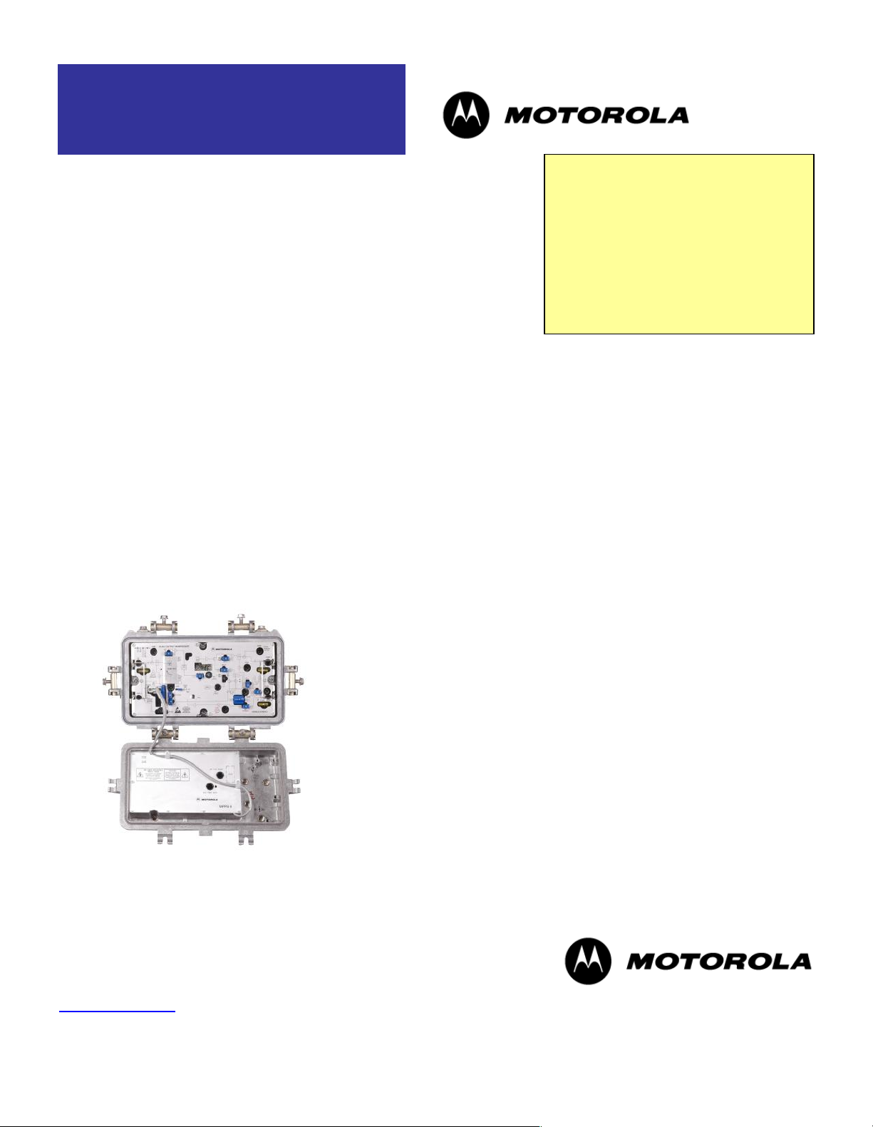
Motorola’s STARLINE® series amplifier, model MB87*/*, leads the industry
The MB87 two-way
amplifier offers 870 MHz
bandwidth capability,
high gain, high output
level, ergonomics, and
superior distortion
performance.
MB87 870 MHz Amplifier
STARLINE Series
BENEFITS INCLUDE:
870 MHz Enhanced Gallium Arsenide (E -GaAs) power
doubling technology
High gain
High output level
Four diplex filter options
Ease-of-use ergonomics
15 dB return loss
60/90 V powering
Meets Telcordia GR-1098-Core voltage surge
requirements using surge waveforms as described in
IEEE C62.41
FCC, CENELEC and CCC approved
Bode equalization (thermal or auto controlled )
15 ampere AC capability
Optional return path ingress control and sta tus monitor
Power factor corrected power supply
Directional coupler –20 dB test points
in features and performance and is designed to meet the needs of today's
expanding broadband communication networks. This two -way capable
dual output amplifier offers high gain, high output levels, ergonomics,
superior distortion performance, four diplex filter options, 15 dB return loss,
and Bode equalization. The MB87*/* also allows opt ional advanced
features such as ingress control switching and status monitoring. A third
output is user-configurable via splitter or directional coupler plug -in. Single
output models are also available.
ENHANCED GALLIUM ARS ENIDE
The MB87 uses Enhanced Gallium Arsenide (E-GaAs) hybrids. This second generation technology provides superior
distortion performance in CTB and CSO over the standard GaAs technology. Compared to silicon and competing GaAs
technology, E-GaAs distortion performance remains linea r at significantly higher output levels. This higher output level
allows the customer to maximize system performance and reduce system costs. We encourage our customers to
contact their Motorola Account Representative to determine the optimal levels for their systems.
HIGH GAIN
The MB87 also offers high gain. This allows the operator to hold existing amplifier locations during system upgrades
thereby reducing system costs.
Page 2

Motorola, Inc.
Connected Home Solutions
101 Tournament Drive
Horsham, PA 19044
1.800.523.6678
www.motorola.com/broadband
Rev. 1.0
09.01.05
MOTOROLA and the Stylized M Logo are registered in the US Patent & Trademark Office.
All other product or service names are the property of their respective owners.
©
Motorola, Inc. 2003
Specifications are subject to change without notice.
2
BACKWARD COMPATIBILITY
The MB87 electronics package can be made backward compatible with the 10 -Amp MB*/* housing by installing the MB 15A Kit or the MB-15A Kit II. These kits contain 50 mil gold plated platform assemblies. This makes it possible for the
amplifier to carry 15 Amperes continuous through the input or out put ports.
FORWARD PATH
The operational gain of the MB87 is 34 dB or 40 dB depending on model , with 15 dB return loss. Output level control is
achieved through the use of an interstage Bode equalizer, which compensates for coaxial cable attenuation cha nges due
to temperature. Equalization may be controlled manually, with a thermal drive unit (model TDU) or with a single pilot
closed loop automatic drive unit (model ADU -* or QADU). Both the TDU and the ADU boards are common to the
STARLINE family of am plifiers (with the exception of the SLE) . ADUs utilize Surface Acoustic Wave (SAW) filters for
determining pilot frequency. This improves amplifier stability over temperature.
To further ensure system flexibility, installation ease and maintenance, the am plifier is engineered for compatibility with
standard accessories, such as attenuators, equalizers, ADUs or TDUs, return amplifiers, automotive fuses and FTEC BTA crowbar circuits.
For an optional third output, the MB87 utilizes splitters (model SP) and di rectional couplers (model DC/*). The SP, DC/8,
DC/10, and DC/12 offer superior performance to 1 GHz.
The MB87 uses modular diplex filters, which can be changed for a different frequency split as required. The amplifier is
available with S-split filters for a 5-40 MHz return and a 52 -870 MHz forward band. K-splits (5-42 MHz/54-870 MHz), Jsplits (5-55 MHz/70-870 MHz), and A-splits (5-65 MHz/85-870 MHz) are also available. These same filters can be used
for all US-style Motorola RF distribution amplifiers (models BLE, MB/MBE, BT).
RETURN PATH
High gain return amplifier kits can be ordered which provide 20 dB minimum station gain. Return path equalizers from 0
to 12 dB can be customer selected. Optional features include thermal compensation and ingress con trol switching.
Thermal compensation comes in the form of a plug -in JXP-TH*C, which stabilizes gain and match over temperature
extremes.
Also available is Ingress Control Switching (ICS) in 3 states. This pin diode attenuator circuit can lower levels by 6 dB or
by 38 dB with a controlled slew rate for minimum bit errors. The dual output MB*/* requires two ingress control switches
when ordering this option (one ICS required for each output). The LIFELINE® MiniBridger Amplifier transponder, model
LL-MB-HMS-*/*, is required to operate the Ingress Control Switch from a remote location.
Model Availability
To reduce customer costs and to accommodate customer specific needs, the STARLINE MB 87 can be ordered in a
variety of different models. Please refer to the MB87 ordering information below for options.
Page 3
Motorola, Inc.
Connected Home Solutions
101 Tournament Drive
Horsham, PA 19044
1.800.523.6678
www.motorola.com/broadband
Rev. 1.0
09.01.05
MOTOROLA and the Stylized M Logo are registered in the US Patent & Trademark Office.
All other product or service names are the property of their respective owners.
©
Motorola, Inc. 2003
Specifications are subject to change without notice.
3
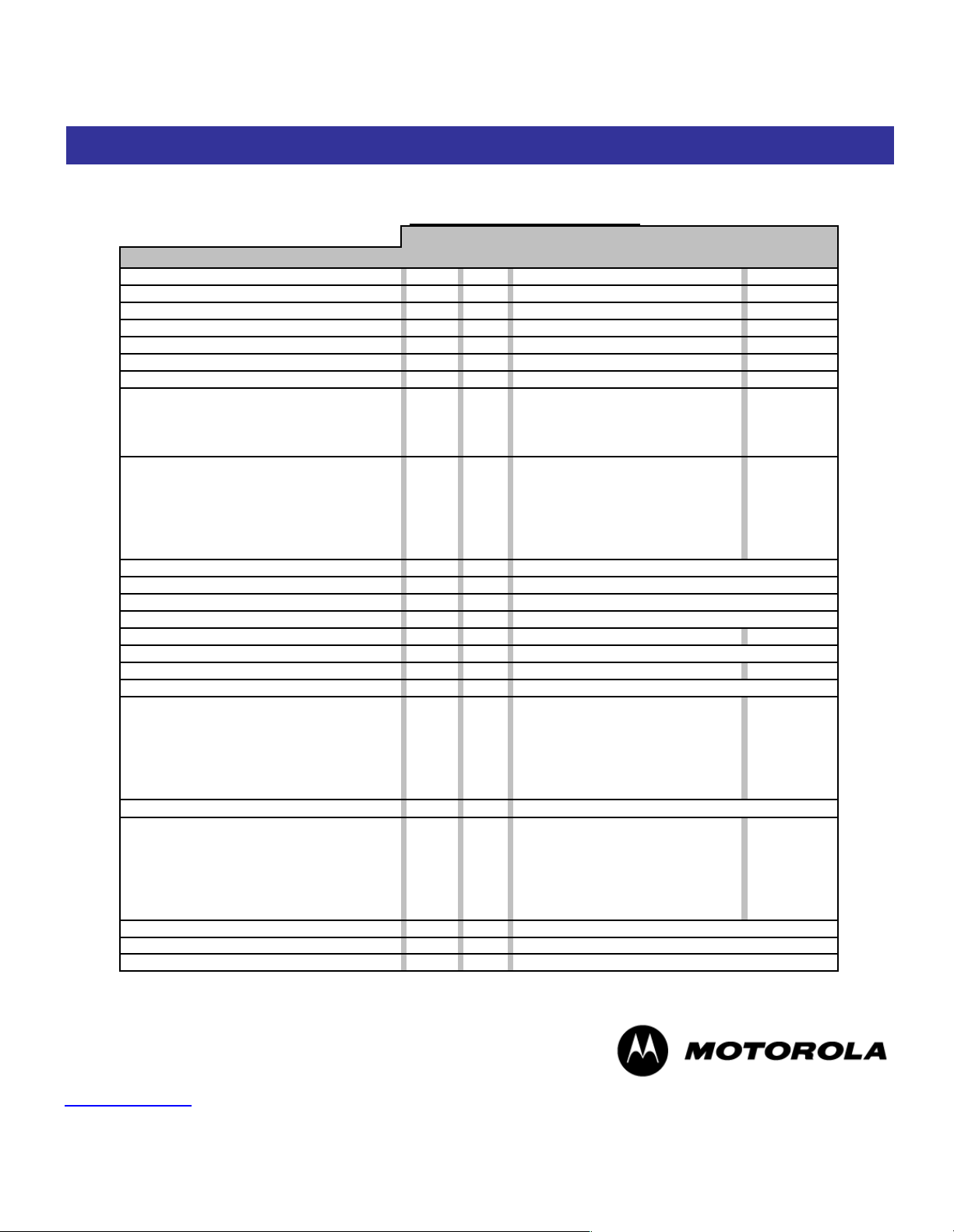
STARLINE®
Enhanced Gallium Arsenide
MB87S/XG* Specifications
MiniBridger Amplifier
RETURN
PARAMETER
UNITS
NOTE
FORWARD
RA-KIT-40H
Passband
MHz15-40
Flatness
dB2± 0.50
Minimum Full Gain
dB3NA
Operational Gain
dB
4
20
Manual Bode Slope Control Range
dB5NA
Interstage Equalizer Slope
dB6NA
Noise Figure 40/52/87 0MHz
dB79 / NA / NA
Reference Frequency
MHz8870 / 550 / 52
40
Output Level
dBmV
43 / 44 / 37
41 FLAT
Channel Loading
NTSC
79
4
Compressed data loading
MHz
320
NA
Distortion (max)
CTB
dBc
9,21,23
75
NAXMdB
10,216569
CSO
dBc
9,11,21
71
NA
CCN (-6)
dBc
12
54
NA
STB
dBc9NA78SSO
dBc9NA76Test Point (all)
dB13Return Loss
dB14Hum Modulation
dBc
15,20
DC Voltage
VDC16Current DC
mA171610
DC Ripple
mV
Power Consumption
W
48
AC Input Voltage Range
VAC
AC Current Draw
@90 VAC
A180.55
@75 VAC
A
0.68
@60 VAC
A
0.81
@53 VAC
A
0.92
@45 VAC
A
1.08
@38 VAC
A
1.31
AC Bypass Current
All Ports
A
18
Group Delay (max)
19
55.25 to 58.83 MHz
nSecNA5.0 to 6.5 MHz
nSec4510.0 to 11.5 MHz
nSec1033.5 to 35.0 MHz
nSec1238.5 to 40.0 MHz
nSec
35
Housing Dimensions
15.4"L x 5.5"W x 9.6"D
39.1cm x 13.97cm x 24.3 cm
Weight
15 Pounds
6.8 kg
Ambient Operating Temperature
-40° to +140° F
-40° to +60° C
NA
NA
2 Port, Parallel E -GaAs Hybrid
NANA 52-870
± 0.70
45301.2
0.51651475400.85
0.95
± 5
12 ±1
NA / 12 / 10
0.74
44.0
0.62151520±
1.0
+ 24.0 ± 0.25
15 P-P
38 - 90
MB87 Specifications
Page 4
Motorola, Inc.
Connected Home Solutions
101 Tournament Drive
Horsham, PA 19044
1.800.523.6678
www.motorola.com/broadband
Rev. 1.0
09.01.05
MOTOROLA and the Stylized M Logo are registered in the US Patent & Trademark Office.
All other product or service names are the property of their respective owners.
©
Motorola, Inc. 2003
Specifications are subject to change without notice.
4
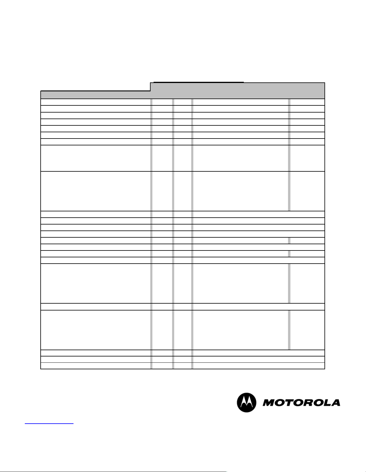
STARLINE®
Enhanced Gallium Arsenide
MB87S/XG* Specifications
with low gain option P
MiniBridger Amplifier
RETURN
PARAMETER
UNITS
NOTE
FORWARD
RA-KIT-40H
Passband
MHz15-40
Flatness
dB2± 0.50
Minimum Full Gain
dB3NA
Operational Gain
dB
4
20
Manual Bode Slope Control Range
dB5NA
Interstage Equalizer Slope
dB6NA
Noise Figure 40 / 52 / 870MHz
dB79 / NA / NA
Reference Frequency
MHz8870 / 550 / 52
40
Output Level
dBmV
43 / 44 / 37
41 FLAT
Channel Loading
NTSC
79
4
Compressed data loading
MHz
320
NA
Distortion (max)
CTB
dBc
9,21,23
75
NA
XM
dB
10,216569
CSO
dBc
9,11,21
75
NA
CCN (-6)
dBc
12
54
NA
STB
dBc9NA78SSO
dBc9NA
76
Test Point (all)
dB13Return Loss
dB
14
Hum Modulation
dBc
15,20
DC Voltage
VDC16Current DC
mA171610
DC Ripple
mV
Power Consumption
W
48
AC Input Voltage Range
VAC
AC Current Draw
@90 VAC
A180.55
@75 VAC
A
0.68
@60 VAC
A
0.81
@53 VAC
A
0.92
@45 VAC
A
1.08
@38 VAC
A
1.31
AC Bypass Current
All Ports
A
18
Group Delay (max)
19
55.25 to 58.83 MHz
nSecNA5.0 to 6.5 MHz
nSec4510.0 to 11.5 MHz
nSec1033.5 to 35.0 MHz
nSec
12
38.5 to 40.0 MHz
nSec
35
Housing Dimensions
15.4"L x 5.5"W x 9.6"D
39.1cm x 13.97cm x 24.3 cm
Weight
15 Pounds
6.8 kg
Ambient Operating Temperature
-40° to +140° F
-40° to +60° C
NA
2 Port, Parallel E -GaAs Hybrid
NANA52-870
± 0.60
396530
1.2
0.51NA0.74
15 P-P
38 - 90
0.624414751534
0.85
0.95
± 5
12 ±1
NA / 12 / 10
20±1.0
15
+ 24.0 ± 0.25
Page 5

Motorola, Inc.
Connected Home Solutions
101 Tournament Drive
Horsham, PA 19044
1.800.523.6678
www.motorola.com/broadband
Rev. 1.0
09.01.05
MOTOROLA and the Stylized M Logo are registered in the US Patent & Trademark Office.
All other product or service names are the property of their respective owners.
©
Motorola, Inc. 2003
Specifications are subject to change without notice.
5
STARLINE®
Enhanced Gallium Arsenide
MB87S/SG* Specifications
MiniBridger Amplifier
RETURN
PARAMETER
UNITS
NOTE
FORWARD
RA-KIT-40H
Passband
MHz15-40
Flatness
dB2± 0.50
Minimum Full Gain
dB3NA
Operational Gain
dB
4
20
Manual Bode Slope Control Range
dB5NA
Interstage Equalizer Slope
dB6NA
Noise Figure 40/52/870MHz
dB79.5 / NA / NA
Reference Frequency
MHz8870 / 550 / 52
40
Output Level
dBmV
43 / 44 / 37
41 FLAT
Channel Loading
NTSC
79
4
Compressed data loading
MHz
320
NA
Distortion (max)
CTB
dBc
9,21,23
75
NAXMdB
10,216569
CSO
dBc
9,11,21
71
NA
CCN (-6)
dBc
12
54
NA
STB
dBc9NA78SSO
dBc9NA76Test Point (all)
dB13Return Loss
dB14Hum Modulation
dBc
15,20
DC Voltage
VDC16Current DC
mA171610
DC Ripple
mV
Power Consumption
W
48
AC Input Voltage Range
VAC
AC Current Draw
@90 VAC
A180.39
@75 VAC
A
0.48
@60 VAC
A
0.57
@53 VAC
A
0.65
@45 VAC
A
0.75
@38 VAC
A
0.93
AC Bypass Current
All Ports
A
18
Group Delay (max)
19
55.25 to 58.83 MHz
nSecNA5.0 to 6.5 MHz
nSec4510.0 to 11.5 MHz
nSec1033.5 to 35.0 MHz
nSec1238.5 to 40.0 MHz
nSec35Housing Dimensions
15.4"L x 5.5"W x 9.6"D
39.1cm x 13.97cm x 24.3 cm
Weight
15 Pounds
6.8 kg
Ambient Operating Temperature
-40° to +140° F
-40° to +60° C
NA
NA
1 Port, Single E-GaAs Hybrid
NANA 52-870
± 0.70
456530
0.82
0.34
38 - 90
15400.57
0.67
± 5
12 ±1
NA / 13 / 11
0.51
44.0
0.42
147520±
1.0
15
+ 24.0 ± 0.25
15 P-P
Page 6

Motorola, Inc.
Connected Home Solutions
101 Tournament Drive
Horsham, PA 19044
1.800.523.6678
www.motorola.com/broadband
Rev. 1.0
09.01.05
MOTOROLA and the Stylized M Logo are registered in the US Patent & Trademark Office.
All other product or service names are the property of their respective owners.
©
Motorola, Inc. 2003
Specifications are subject to change without notice.
6
STARLINE®
Enhanced Gallium Arsenide
MB87S/SG* Specifications
with low gain option P
MiniBridger Amplifier
RETURN
PARAMETER
UNITS
NOTE
FORWARD
RA-KIT-40H
Passband
MHz15-40
Flatness
dB2± 0.50
Minimum Full Gain
dB3NA
Operational Gain
dB
4
20
Manual Bode Slope Control Range
dB5NA
Interstage Equalizer Slope
dB6NA
Noise Figure 40/52/870MHz
dB79.5 / NA / NA
Reference Frequency
MHz8870 / 550 / 52
40
Output Level
dBmV
43 / 44 / 37
41 FLAT
Channel Loading
NTSC
79
4
Compressed data loading
MHz
320
NA
Distortion (max)
CTB
dBc
9,21,23
75
NAXMdB
10,216569
CSO
dBc
9,11,21
75
NA
CCN (-6)
dBc
12
54
NA
STB
dBc9NA78SSO
dBc9NA76Test Point (all)
dB13Return Loss (min)
dB14Hum Modulation
dBc
15,20
DC Voltage
VDC16Current DC
mA171610
DC Ripple
mV
Power Consumption
W
48
AC Input Voltage Range
VAC
AC Current Draw
@90 VAC
A180.39
@75 VAC
A
0.48
@60 VAC
A
0.57
@53 VAC
A
0.65
@45 VAC
A
0.75
@38 VAC
A
0.93
AC Bypass Current
All Ports
A
18
Group Delay (max)
19
55.25 to 58.83 MHz
nSecNA5.0 to 6.5 MHz
nSec4510.0 to 11.5 MHz
nSec1033.5 to 35.0 MHz
nSec1238.5 to 40.0 MHz
nSec
35
Housing Dimensions
15.4"L x 5.5"W x 9.6"D
39.1cm x 13.97cm x 24.3 cm
Weight
15 Pounds
6.8 kg
Ambient Operating Temperatu re
-40° to +140° F
-40° to +60° C
20±1.0
15
+ 24.0 ± 0.25
15 P-P
65340.57
0.67
± 5
12 ±1
NA / 13 / 11
0.51440.42
1475
0.82
0.34
38 - 9015NA
NA
1 Port, Single E-GaAs Hybrid
NANA 52-870
± 0.70
39
30
Page 7

Motorola, Inc.
Connected Home Solutions
101 Tournament Drive
Horsham, PA 19044
1.800.523.6678
www.motorola.com/broadband
Rev. 1.0
09.01.05
MOTOROLA and the Stylized M Logo are registered in the US Patent & Trademark Office.
All other product or service names are the property of their respective owners.
©
Motorola, Inc. 2003
Specifications are subject to change without notice.
7
Notes:
1. Operating passband of station. Diple x filters are plugged into the electronic chassis.
2. Referenced to the average gain across the stated passband.
3. Minimum full gain at 870 MHz includes loss of equalizer but Bode slope reserves have not been set. Return gain includes loss of SRE -*-4 return
equalizer.
4. Operational gain includes loss of slope reserves as well as equalizer.
5. Amount of Bode slope control range from midpoint (typical setting is -4 dB at 870 MHz @ 20°C). This control should not be used for gain
reduction.
6. Amount of slope created and cable equivalence of fixed interstage equalizer. Interstage equalizer is a plug -in.
7. Noise Figure performance is specified typical. Noise Figure is specified at the cable entry facility of the housing and includes the loss of 1 dB for
the pre-stage equalizer. The return Noise Figure includes the station loss preceding the RF hybrid.
8. Frequencies that relate the picture carriers or passband edges to the specified output levels and tilts.
9. Measured with CW carriers and spectrum analyzer over specified temperature range. References the worst -case channel. Specifications are
compliant with the test methods as stated in NCTA RECOMMENDED PRACTICES FOR MEASUREMENTS ON CABLE TELEVISION
SYSTEMS.
10. Measured with wave analyzer and synchronous, 100% depth modulated channels. References the worst -case channels over specified
temperature range. Specifications are compliant with the test methods as stated in NCTA RECOMMENDED PRACTICES FOR
MEASUREMENTS ON CABLE T ELEVISION SYSTEMS.
11. Composite Second Order distortion refers only to those beat clusters that fall +0.75 MHz and +1.25 MHz above the subject picture carrier. CSO
beat clusters that have a -0.75 MHz and -1.25 MHz relationship to the subject picture car rier are not included in this specification.
12. CCN (Composite, Carrier-to-Noise Ratio) is a 10 log addition of both the Carrier -to-Noise Ratio (CNR) and Carrier -to-Intermodulation Noise Ratio
(CIN).
13. Test points should be used with GFAL adaptor.
14. Match measurement at the station input and output, cable -entry facilities, at the specified passbands for operational gain.
15. Measured with the stated AC Bypass Current.
16. Measured at the power connector.
17. Current draw at +24.0 VDC.
18. AC current is stated in RMS continuous.
19. Group Delay is specified for standard NTSC video, where delay is the delta from picture carrier to 3.58 MHz color subcarrier. Reverse delay is in
a 1.5 MHz bandwidth.
20. Hum Modulation performance is stated typic al. Return band specified from 15 MHz. Hum Modulation (5 MHz to 15 MHz) is –55 dBc.
21. Distortion numbers are worst case over temperature in a cascade.
22. The compressed data loading is QAM carriers and are –6 dB relative to the analog CW carriers.
23. CTB (Composite Triple Beat). At the specified channel loading, Enhanced Gallium Arsenide performance varies on a two point three -for-one
(2.3:1) basis with amplifier output level.
Page 8

Motorola, Inc.
Connected Home Solutions
101 Tournament Drive
Horsham, PA 19044
1.800.523.6678
www.motorola.com/broadband
Rev. 1.0
09.01.05
MOTOROLA and the Stylized M Logo are registered in the US Patent & Trademark Office.
All other product or service names are the property of their respective owners.
©
Motorola, Inc. 2003
Specifications are subject to change without notice.
8
Dual Output
Input
port 1
Port
2
Port
4
Port
3
DC
SP
JMP
RF/
AC
RF/
AC
RF
RF
AC
AC
TP
TP
TP
(Status
Monitor
Output)
TP
TP
TP
Manual Auto
H
L
**
** ** ** **
**
**
**
JXP-B
JXP-B
JXP-B
JXP-B
MDR
BODE
** **
**
**** **
** **
**
SRE
JXP-B
THERM
** **
JXPICS
JXPICS
Fuse
**
**
Fuse
Fuse
Fuse
Power
supply
Plug-in
module
24 Vdc
****
JXP-B
ADU/
TDU
RF/AC
RF
AC
DC/
SP/
JMP
RF/
AC
RF
AC
To status
monitor
**
H
L
-1.0dB
-1.0dB
-1.0dB
+19.0 dB
Fltn.
Cntrl.
-3.5 dB -6.5 dB -1.0 dB +19.0 dB
-4.0 dB
-4.0 dB
H
L
**
-1.0dB
-1.0dB
-1.5 dB F
-1.0 dB R
-20 dB
-20 dB
-20 dB
-20 dB
-20 dB
-20 dB
-1.5 dB F
-1.0dB R
-1.8 dB F
-1.0dB
-1.0dB
SFE
or
SCS
PD
PD
PPPP
-1.0 dB R
-0.4dB
-0.5dB
Status
Monitor
Input
**
JXP-B
-16 dB
+25.0dB L
+30.0dB H
-0.3dB
-4.0 dB
-4.0 dB
-0.4dB
-0.4dB
-0.4dB
+18 dB Low Gain
+23 dB High Gain
JXP-B
JXP-B
OnBrd
Atten
LPF
-0.4 dB
+18 dB Low Gain
+23 dB High Gain
E-GaAs
E-GaAs
Input
port 1
Port
4
Port
3
DC
SP JMP
RF/
AC
RF
AC
TP
TP
Status
Monitor
Output
TP
TP
Manual Auto
H
L
**
**
** **
** ******
SFE
or
SCS
JXP-B
JXP-B
JXP-B
MDRBODE
H
** **
**
****
**
** **
**
SRE JXP-B JXP-BTHERM
L
JXPICS
Fuse
**
**
Fuse
Fuse
Power
supply
Plug-in
module
24 Vdc
****
JXP-B
ADU/
TDU
RF/AC
RF
AC
RF/
AC
RF
AC
To status
monitor
Fltn.
Cntrl.
-20 dB
-20 dB
-20 dB
-20 dB
-16 dB
DC/
SP/
JMP
PP PP
JXP-B
LPF
OnBrd
Atten
-1.5 dB F
-1.0 dB R
-1.0dB
-1.0dB
-1.0dB +19.0 dB -3.5 dB -6.5 dB
-1.0 dB +19.0 dB
+18 dB Low Gain
+23 dB High Gain
PD
-0.4dB
-0.5dB
+25.0dB L
+30.0dB H
-0.3dB
-0.4dB
-0.4dB
-1.0dB
-1.0dB
-0.4dB
-1.8 dB F
-1.0dB R
Status
Monitor
Input
-4.0 dB
MB87 Block Diagram
Single Output
Page 9

Motorola, Inc.
Connected Home Solutions
101 Tournament Drive
Horsham, PA 19044
1.800.523.6678
www.motorola.com/broadband
Rev. 1.0
09.01.05
MOTOROLA and the Stylized M Logo are registered in the US Patent & Trademark Office.
All other product or service names are the property of their respective owners.
©
Motorola, Inc. 2003
Specifications are subject to change without notice.
9
Model
Description
Motorola
Part Number
Qty
per MB
STANDARD MB MODELS
S-SPLIT
MB87S/XGXX-HXX-XXX-XC-XXX-XXX-E
5-40 / 52-870 MHz split, two-output, E-GaAs, manual gain
control, 12 dB internal slope, high gain return, 40 dB high gain
forward, 20A fuses, FTEC, full station
795005-047-00
MB87S/XGAX-HXX-XXX-XC-XXX-XXX-E
5-40 / 52-870 MHz split, two-output, E-GaAs, ADU 499.25 MHz
gain control, 12 dB internal slope, high gain return, 40 dB high
gain forward, 20A fuses, FTEC, full station
795005-002-00
MB87S/XGTX-HXX-XXX-XC-XXX-XXX-E
5-40 / 52-870 MHz split, two-output, E-GaAs, TDU gain control,
12 dB internal slope, high gain return, 40 dB high gain forward,
20A fuses, FTEC, full station
795005-043-00
MB87S/XGXX-HXX-XPX-XC-XXX-XXX-E
5-40 / 52-870 MHz split, two-output, E-GaAs, manual gain
control, 12 dB internal slope, high gain return, 34 dB low gain
forward, 20A fuses, FTEC, full station
795005-116-00
MB87S/XGAX-HXX-XPX-XC-XXX-XXX-E
5-40 / 52-870 MHz split, two-output, E-GaAs, ADU 499.25 MHz
gain control, 12 dB internal slope, high gain return, 34 dB low
gain forward, 20A fuses, FTEC, full station
795005-072-00
MB87S/XGTX-HXX-XPX-XC-XXX-XXX-E
5-40 / 52-870 MHz split, two-output, E-GaAs, TDU gain control,
12 dB internal slope, high gain return, 34 dB low gain forward,
20A fuses, FTEC, full station
795005-250-00
MB87S/XGXX-HXX-XXX-XX-XXX-XXX-E
5-40 / 52-870 MHz split, two-output, E-GaAs, manual gain
control, 12 dB internal slope, high gain return, 40 dB high gain
forward, 20A fuses, standard surge arrestor, full station
795005-051-00
K-SPLIT
MB87K/XGXX-HXX-XXX-XC-XXX-XXX-E
5-42 / 54-870 MHz split, two-output, E-GaAs, manual gain
control, 12 dB internal slope, high gain return, 40 dB high gain
forward, 20A fuses, FTEC, full station
795005-284-00
MB87K/XGXX-HXX-XXX-XX-XXX-XXX-E
5-42 / 54-870 MHz split, two-output, E-GaAs, manual gain
control, 12 dB internal slope, high gain return, 40 dB high gain
forward, 20A fuses, standard surge arrestor, full station
795005-054-00
MB87K/XGAX-HXX-XXX-XC-XXX-XXX-E
5-42 / 54-870 MHz split, two-output, E-GaAs, ADU 499.25 MHz
gain control, 12 dB internal slope, high gain return, 40 dB high
gain forward, 20A fuses, FTEC, full station
795005-243-00
MB87K/XGXX-HXX-XPX-XC-XXX-XXX-E
5-42 / 54-870 MHz split, two-output, E-GaAs, manual gain
control, 12 dB internal slope, high gain return, 34 dB low gain
forward, 20A fuses, FTEC, full station
795005-088-00
A-SPLIT
MB87A/XGXX-HXX-XXX-XX-XXX-XXX-E
5-65 / 85-870 MHz split, two-output, E-GaAs, manual gain
control, 12 dB internal slope, h igh gain return, 40 dB high gain
forward, 20A fuses, standard surge arrestor, full station
795005-034-00
J-SPLIT
MB87J/XGTX-HXX-XXX-XC-XXX-XXX-E
5-55 / 70-870 MHz split, two-output, E-GaAs, TDU gain control,
12 dB internal slope, high gain return, 40 dB high gain forward,
20A fuses, FTEC, full station
795005-293-00
MB87 Ordering Information
Page 10

Motorola, Inc.
Connected Home Solutions
101 Tournament Drive
Horsham, PA 19044
1.800.523.6678
www.motorola.com/broadband
Rev. 1.0
09.01.05
MOTOROLA and the Stylized M Logo are registered in the US Patent & Trademark Office.
All other product or service names are the property of their respective owners.
©
Motorola, Inc. 2003
Specifications are subject to change without notice.
10
NON-STANDARD MB MODELS
MB87S/SGXX-HXX-XXX-XC-XXX-XXX-E
5-40 / 52-870 MHz split, one-output, E-GaAs, manual gain
control, 12 dB internal slope, high gain return, 40 dB high gain
forward, 20A fuses, FTEC, full station
795005-291-00
MB87S/XGXX-HXX-XXX-XX-NXX-XXX-E
5-40 / 52-870 MHz split, two-output, E-GaAs, manual gain
control, 12 dB internal slope, high gain return, 40 dB high gain
forward, 20A fuses, 15 A electronics module only (no hou sing)
795005-287-00
MB75S/XGXX-HXX-XXX-XC-XXX-XXX-E
5-40 / 52-750 MHz split, two-output, E-GaAs, manual gain
control, 12 dB internal slope, high gain return, 40 dB high gain
forward, 20A fuses, FTEC, full station
795005-199-00
MB87K/SGXX-HXX-XXX-XC-XXX-XXX-E
5-42 / 54-870 MHz split, one-output, E-GaAs, manual gain
control, 12 dB internal slope, high gain return, 40 dB high gain
forward, 20A fuses, FTEC, full station
795005-310-00
MB87K/XGXX-HXX-XXX-XX-NXX-XXX-E
5-42 / 54-870 MHz split, two-output, E-GaAs, manual gain
control, 12 dB internal slope, high gain return, 40 dB high gain
forward, 20A fuses, 15 A electronics module only (no housing)
795005-311-00
MB87A/XGXX-HXX-XXX-XX-NXX-XXX-E
5-65 / 85-870 MHz split, two-output, E-GaAs, manual gain
control, 12 dB internal slope, high gain return, 40 dB high gain
forward, 20A fuses, standard surge arrestor, 15 A electronics
module only (no housing)
795005-312-00
MB87J/XGXX-XXX-XXX-XX-XXX-XXX-E
5-55 / 70-870 MHz split, two-output, E-GaAs, manual gain
control, 12 dB internal slope, no return, 40 dB high gain forward,
20A fuses, standard surge arrestor, full station
795005-027-00
Accessories
SFE-0
or SFE-1
or SFE-87-*
or SFE-75-*
or SCS-*
Starline Forward Equalizer, 5 – 1 GHz, 0 dB
Starline Forward Equalizer, 5 – 1 GHz, 1 dB
Starline Forward 870 MHz equalizer (0 to 22 dB in 1 dB steps)
Starline Forward 750 MHz equalizer (0 to 22 dB in 1 dB steps)
Starline Cable Simulators
479309-001-00
479309-002-00
477725-*
477822-*
477888-*
1
SRE-*-*
Starline Return Equalizer, 5-40 MHz (S-split), 5-42 (K-split), 5-55
(J-split), 5-65 (A-split), values 0-12 dB in 1 dB steps for S -split (2
dB steps for all other frequency splits)
478176-*
1
JXP-*B
Plug-in attenuator/pad (values 0 to 26 dB, in 1 dB steps)
474011-*
9 (dual)
7 (single)
SP
Splitter
478657-001-00
1 (optional)
DC/8
DC/10
DC/12
Directional Coupler, 8 dB
Directional Coupler, 10 dB
Directional Coupler, 12 dB
478658-001-00
478658-002-00
478658-003-00
1 (optional)
Page 11

Motorola, Inc.
Connected Home Solutions
101 Tournament Drive
Horsham, PA 19044
1.800.523.6678
www.motorola.com/broadband
Rev. 1.0
09.01.05
MOTOROLA and the Stylized M Logo are registered in the US Patent & Trademark Office.
All other product or service names are the property of their respective owners.
©
Motorola, Inc. 2003
Specifications are subject to change without notice.
11
Key
X Key
S X
N
Key
G
Key
*
Other ADU values available for separate purchase, see accessory list for details
X
Key
X Key Key
T X X
A
MB
-
G X
-
X X
-
X X
-
X
-
X X
-
X X X
-
E
Key Key
87S X
87K P
87A Key
87J H Key
X
Key
C
X
**
Other slope values may be created by
varying the forward input equalizer value
Reserved
Reserved
Bandpass Split
ADU - 499.25/S
TDU
None
MOTOROLA Standard MiniBridger Model Guide/Description
5 - 42 MHz / 54 - 870 MHz
Reserved
Reserved
Two-port
One-port
Level Control
*
RF Configuration
Hybrid Technology
Standard (15 Amp)
AC Current Capability
E-GaAs (High Output)
Housing
No Housing (electronics only - 15 Amp)
Standard (Full Station)
Special Options
40 dB Gain
34 dB Gain
5 - 55 MHz / 70 - 870 MHz
5 - 40 MHz / 52 - 870 MHz
5 - 65 MHz / 85 - 870 MHz
Return Gain
High (20 dB)
FTEC (Fast Transfer Electronic Crowbar)
Gas Tube Surge Arrestor
Voltage Surge Protection
12 dB (Fmin - 870 MHz)
Station Slope
**
Page 12

Motorola, Inc.
Connected Home Solutions
101 Tournament Drive
Horsham, PA 19044
1.800.523.6678
www.motorola.com/broadband
Rev. 1.0
09.01.05
MOTOROLA and the Stylized M Logo are registered in the US Patent & Trademark Office.
All other product or service names are the property of their respective owners.
©
Motorola, Inc. 2003
Specifications are subject to change without notice.
12
Model P/N Description
ADU-* 928129-* Automatic drive unit
ADU-499.25/S 928129-017 Automatic drive unit - pilot at 499.25 MHz (uses SAW filter)
ADU-439.25/S 928129-018 Automatic drive unit - pilot at 439.25 MHz (uses SAW filter)
ADU-403.25/S 928129-019 Automatic drive unit - pilot at 403.25 MHz (uses SAW filter)
ADU-445.25/S 928129-020 Automatic drive unit - pilot at 445.25 MHz (uses SAW filter)
ADU-549.00/S 928129-010 Automatic drive unit - pilot at 549.00 MHz (uses SAW filter)
ADU-423.25 928129-023 Automatic drive unit - pilot at 423.25 MHz
ADU-498.00 928129-009 Automatic drive unit - pilot at 498.00 MHz
QADU-609.00/S 928129-026 QAM Automatic drive unit - QAM pilot at 609 MHz (uses SAW filter)
F/JXP-20 927714-001 Test probe
FTEC/BTA 928103-000 Fast transfer electronic crowbar surge protector (230V)
FTEC-145 928103-001 Fast transfer electronic crowbar surge protector (145V)
Fuses 928303-tab Automotive style fuses
Shunts 928303-000 35A automotive style fuses
GFAL 927709-000 Test probe
ICS-II 454056-002 Ingress control switch for amplifiers
JXP-75T 927265-075 75 ohm terminator (short profile)
JXP-RC 927703-002 Forward path (full band) correction board
JXP-RPC 927703-003 Return path correction board (mid-band)
JXP-TH2C 479310-007 2 dB plug-in thermal pad used in return path (two-tier ergonomic)
JXP-TH3C 479310-008 3 dB plug-in thermal pad used in return path (two-tier ergonomic)
LL-MB-HMS-*/* 515883-* Lifeline transponder for MB (HMS compliant)
MB 15A Kit 951941-005 For MB-550D-H or MB-750D-H upgrade to 15 amps
MB 15AII Kit 951941-007 For MB-75SH upgrade to 15 amps
MPPSII/CVR 484020-001 MB housing lid with MPPS-II (230Vac) power supply
MPPSII/HSG 482592-001 MB housing with MPPS-II (230Vac) power supply
MPPS-II/FJ 518530-001 Field jumper cable kit for MPPS-II to reduce power noise
RA-KIT/H 927810-007 Return path kit (high gain)
RA-KIT/L 927810-006 Return path kit (low gain)
TDU 928119-000 Thermal drive unit
SHP 815 447983-001 Return high pass filter (15 - 65 MHz)
SHP 815-II 447983-003 Return high pass filter (15 - 65 MHz) - smaller design
SHP 825 447983-002 Return high pass filter (25 - 65 MHz) - smaller design
SZW 852 516299-001 Diplex filter, 40/52 MHz S-split
SZW 854
478005-001
Diplex filter, 42/54 MHz K-split
SZW 885
440168-001
Diplex filter, 65/85 MHz A-split
SZW 870 516301-001 Diplex filter, 55/70 MHz J-split
SZW 847
447280-001
Diplex filter, 30/47 MHz E-split
Other Accessories for MB87
 Loading...