

Mitsubishi PUH-1.6VKA3.UK, PUH-2NKA1.K, PUH-2VKA2.UK, PUH-2.5VKA2.UK, PUH-3VKA2.UK Service Manual
...Page 1
SPLIT-TYPE, HEAT PUMP AIR CONDITIONERS
OUTDOOR UNIT
TECHNICAL & SERVICE MANUAL
Outdoor unit
[Model names] [Service Ref.]
1997
No.OC150
REVISED EDITION-A
PUH-1.6VKA PUH-1.6VKA
PUH-2VKA,2NKA PUH-2VKA
2
.UK,PUH-2NKA1.UK
PUH-2.5VKA,2.5NKA PUH-2.5VKA
PUH-3VKA,3NKA PUH-3VKA
PUH-3YKA PUH-3YKA
PUH-4YKSA,4TKSA PUH-4YKSA
PUH-5YKSA PUH-5YKSA
PUH-6YKSA PUH-6YKSA
2
.UK,PUH-3NKA1.UK
2
.UK
2
2
2
CONTENTS
1.
COMBINATION OF INDOOR AND OUTDOOR UNITS
2. PART NAMES AND FUNCTIONS·····················3
3. DATA··································································4
4. OUTLINES AND DIMENSIONS························5
5. WIRING DIAGRAM ···········································9
6.
REFRIGERANT SYSTEM DIAGRAM
7. DISASSEMBLY PROCEDURE ·······················19
8. PARTS LIST····················································21
9. OPTIONAL PARTS ························Back Cover
3
.UK
2
.UK,PUH-2.5NKA1.UK
.UK,4TKSA1.UK
.UK
.UK
················17
·····2
Revision:
●Parts List has been partially modified.
(Marking W in the PARTS LIST has been
changed the PARTS LIST in OC150.)
●Please discard OC150.
The Slim Line.
From Mitsubishi Electric.
Page 2
1 COMBINATION OF INDOOR AND OUTDOOR UNITS
Indoor unit Outdoor unit
Service Ref.
PLH-GKH(S)B1·UK
PLH-GK(S)B1·UK
PLH-GKH(S)B
PLH-GK(S)B
1
1
PLH-KKHB·UK
PLH-KKB·UK
)A
)A
1
1
2
PCH-GKH(S
PCH-GK(S
PKH-1.6/2FKHA3, 2.5/3/4FKH(S)A
PKH-2FKA3, 2.5/3/4FK(S)A2
PSH-GJH(S)A
1
PEHD-EKH(S)A·UK
PEHD-EK(S)A·UK
Service
Manual No.
OC148
OC139
OC107
OC147
OC119
OC135
OC136
OC130
OC132
OC142
—
1.6
VKA,VKA3.UK
—
—
—
—
—
—
—
—
—
—
VKA2.UK
—
—
—
—
—
—
—
NKA1.UK
—
—
—
—
—
—
—
—
—
—
—
—
VKA2.UK
—
—
—
—
—
—
NKA1.UK
—
—
—
—
—
—
—
—
—
—
—
—
VKA2.UK
—
—
342 2.5
YKA2.UK
—
—
NKA1.UK
—
—
—
—
—
—
—
—
YKSA2.UK
—
—
TKSA1.UK
—
—
—
—
—
—
—
—
5
YKSA2.UK
—
—
—
—
—
—
6
YKSA2.UK
—
—
—
—
—
—
—
—
2
Page 3
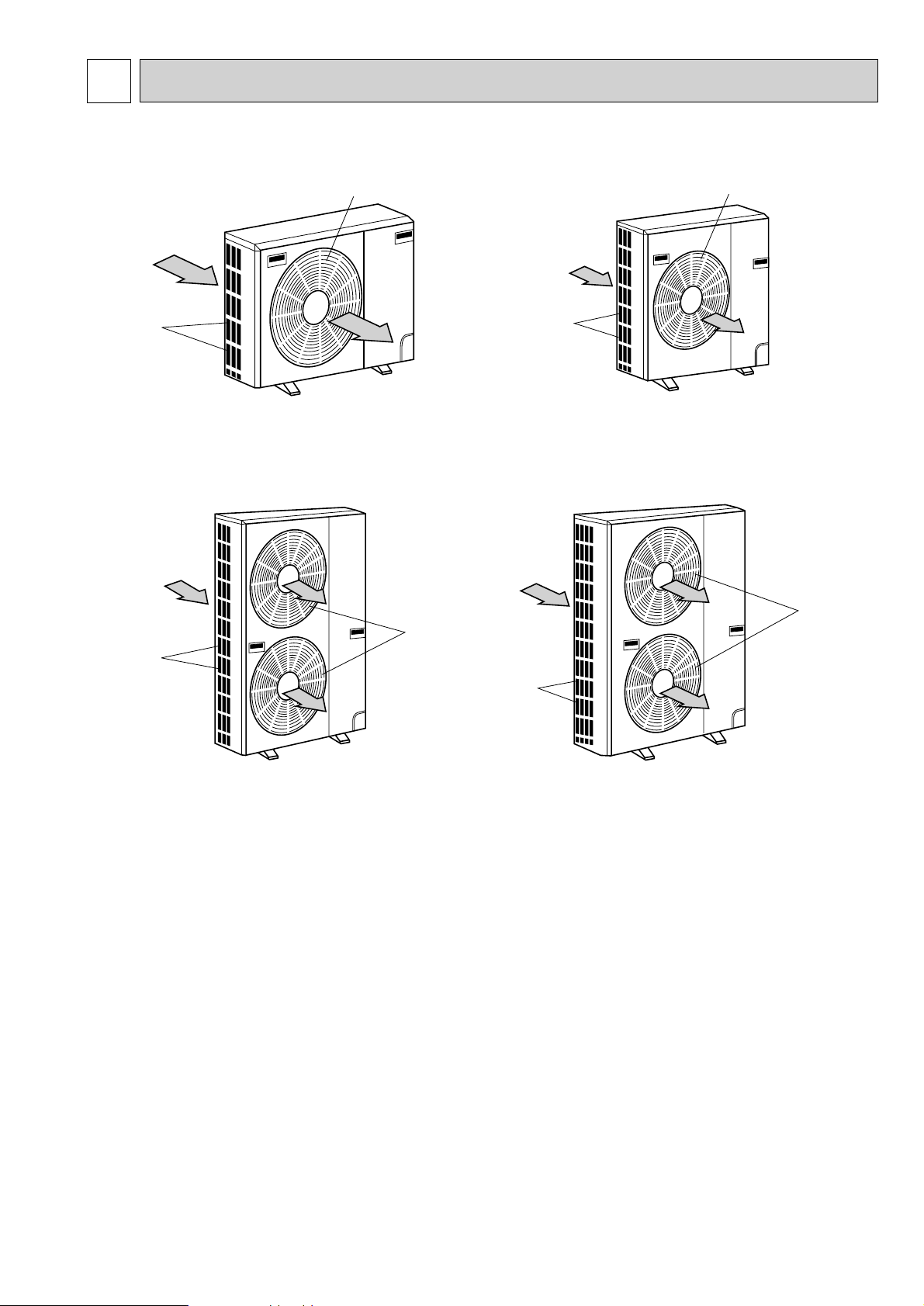
2 PART NAMES AND FUNCTIONS
PUH-1.6VKA3,2VKA2,2NKA1·UK
Air intake
Air outlet
(Expels warm air during cooling)
PUH-4YKSA2·UK
4TKSA
1·UK
Air intake
Air outlet
PUH-5YKSA2·UK
6YKSA
2·UK
Air intake
Air outlet
PUH-2.5VKA2,2.5NKA1,3VKA2,3YKA2,3NKA1·UK
Air intake
Air outlet
CHARGELESS SYSTEM
PRE-CHARGED REFRIGERANT IS SUPPLIED FOR UP TO 30m PIPING LENGTH AT SHIPMENT.
The unique refrigerant circuit and a large accumulator always control the optimal refrigerant level regardless of the length
(50m max. and 5m min.) of piping. The additional refrigerant charging work during installation often causes problems.
Therefore, it is completely eliminated. This unique system improves the quality and reliability of the work done. It also helps
to speed up the installation work.
3
Page 4
3 DATA
1. REFILLING REFRIGERANT CHARGE (R-22 : kg)
Service Ref.
PUH-1.6VKA3·UK
PUH-2VKA
PUH-2NKA
PUH-2.5VKA
PUH-2.5NKA
PUH-3VKA
PUH-3NKA
PUH-3YKA
PUH-4YKSA
PUH-4TKSA
PUH-5YKSA
PUH-6YKSA
2·UK
1·UK
2·UK
1·UK
2·UK
1·UK
2·UK
2
·UK
1
·UK
2·UK
2·UK
5m
1.5
1.5
2.1
2.5
2.5
3.5
4.0
4.7
4.3
10m
1.7
1.7
2.3
2.7
2.7
3.6
4.1
4.8
4.4
15m
1.8
1.8
2.4
2.8
2.8
3.8
4.3
5.0
4.6
2. COMPRESSOR TECHNICAL DATA
Outdoor unit
Compressor Model
Winding
Resistance
(Ω)
at 20˚C
U-V
(
R-C
U-W
(
S-C
W-V
PUH-1.6
VKA
RH247VFC
2.00
)
4.55
)
3
—
·UK
PUH-2
2
VKA
·UK
NH38VMD
1.05
2.23
—
PUH-2
NKA
NHJ33NBD
0.70
1.44
—
Refrigerant piping length (one way)
1
·UK
20m
1.9
1.9
2.5
2.9
2.9
3.9
4.4
5.1
4.7
PUH-2.5
VKA
NH41VMD
1.03
2.22
—
2
·UK
25m
2.1
2.1
2.7
3.1
3.1
4.1
4.6
5.3
4.9
PUH-2.5
1
NKA
·UK
NHJ38NBD
0.70
1.42
—
30m
2.2
2.2
2.8
3.2
3.2
4.2
4.7
5.4
5.0
PUH-3
2
VKA
·UK
NH52VND
0.83
2.03
—
35m
2.3
2.3
2.9
3.3
3.3
4.4
4.9
5.6
5.2
PUH-3
1
NKA
·UK
NHJ47NAD
0.58
1.14
—
40m
2.4
2.4
3.0
3.4
3.4
4.5
5.0
5.7
5.3
PUH-3
2
YKA
·UK
NH52YDA
3.60
3.60
3.60
45m
—
—
3.1
3.6
3.6
4.6
5.1
5.9
5.5
PUH-4
2
YKSA
·UK
NH56YDA
3.50
3.50
3.50
50m
—
—
3.3
3.7
3.7
4.8
5.3
6.0
5.6
PUH-4
1
TKSA
·UK
NHJ56TKA
0.83
0.83
0.83
Outdoor unit
Compressor Model
Winding
Resistance
(Ω)
at 25˚C
1-T2
T
T2-T
T3-T
PUH-5YKSA
ZR61K3TFD
2.53-2.91
3
1
2.53-2.91
2.53-2.91
2
·UK
PUH-6YKSA2·UK
ZR68KCTFD
2.31
2.31
2.31
4
Page 5
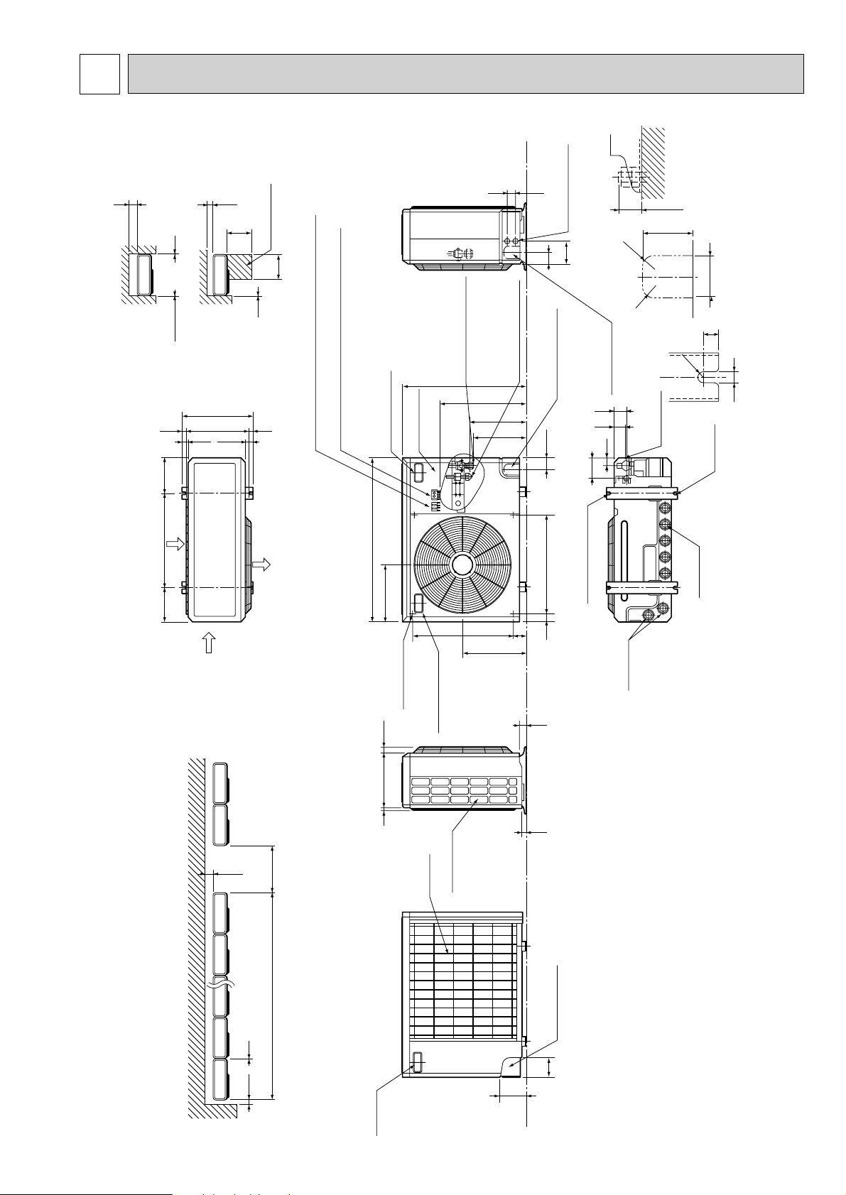
4 OUTLINES AND DIMENSIONS
100 10
1000For 10 units or less
200
Outdoor Unit-Necessary surrounding clearance
(Concentrated installation)
The upper side must be open.
Outdoor Unit-Necessary surrounding clearance
200
10
10
10
Note:Allow adequate
upper clearance
100
500
500
Service space
Front opening
Handle
for moving
138
95
Rear piping hole
23
33
Rear fresh
air intake
Side air intake
7 24(1)295(11-5/8)
Outlet guide
installation hole
302
Air intake
Air intake
Air outlet
870(34-1/4)
185
(7-9/32)
185
(7-9/32)
500(19-11/16)
330(13)
362(14-1/4)
1715
39.5 27.5
Terminal block for indoor and outdoor unit connection
Terminal block for power line and Ground terminal
Handle for moving
77
524
339
282
297
444
650 (25-5/8)
40 60524
Service panel
Refrigerant-pipe flared
connection
[15.88 3/8F
Refrigerant-pipe flared
connection
[9.52 3/8F
Knock out hole
for front piping
(refrigerant,drainage
and wiring)
Knock out hole
for right piping
(refrigerant,drainage
and wiring)
R
20
R20
60
120
4553
25 max.
Knock out holes for
power line 2-[27
Standard bolt length
65
Front right piping holes-
detail figures
80
17
42
45
12
R6
104
33
Bottom
piping hole
2-U-shaped
notched
holes
Drain hole
Drain hole
2-12o23 Oval holes
(standard bolt M10)
Handle for moving
PUH-1.6VKA3·UK,PUH-2VKA2·UK,PUH-2NKA1·UK Unit : mm (inch)
5
Page 6
100 10
1000For 10 units or less
200
Outdoor Unit-Necessary surrounding clearance
(Concentrated installation)
The upper side must be open.
Outdoor Unit-Necessary surrounding clearance
200
10
10
10
Note:Allow adequate
upper clearance
100
500
500
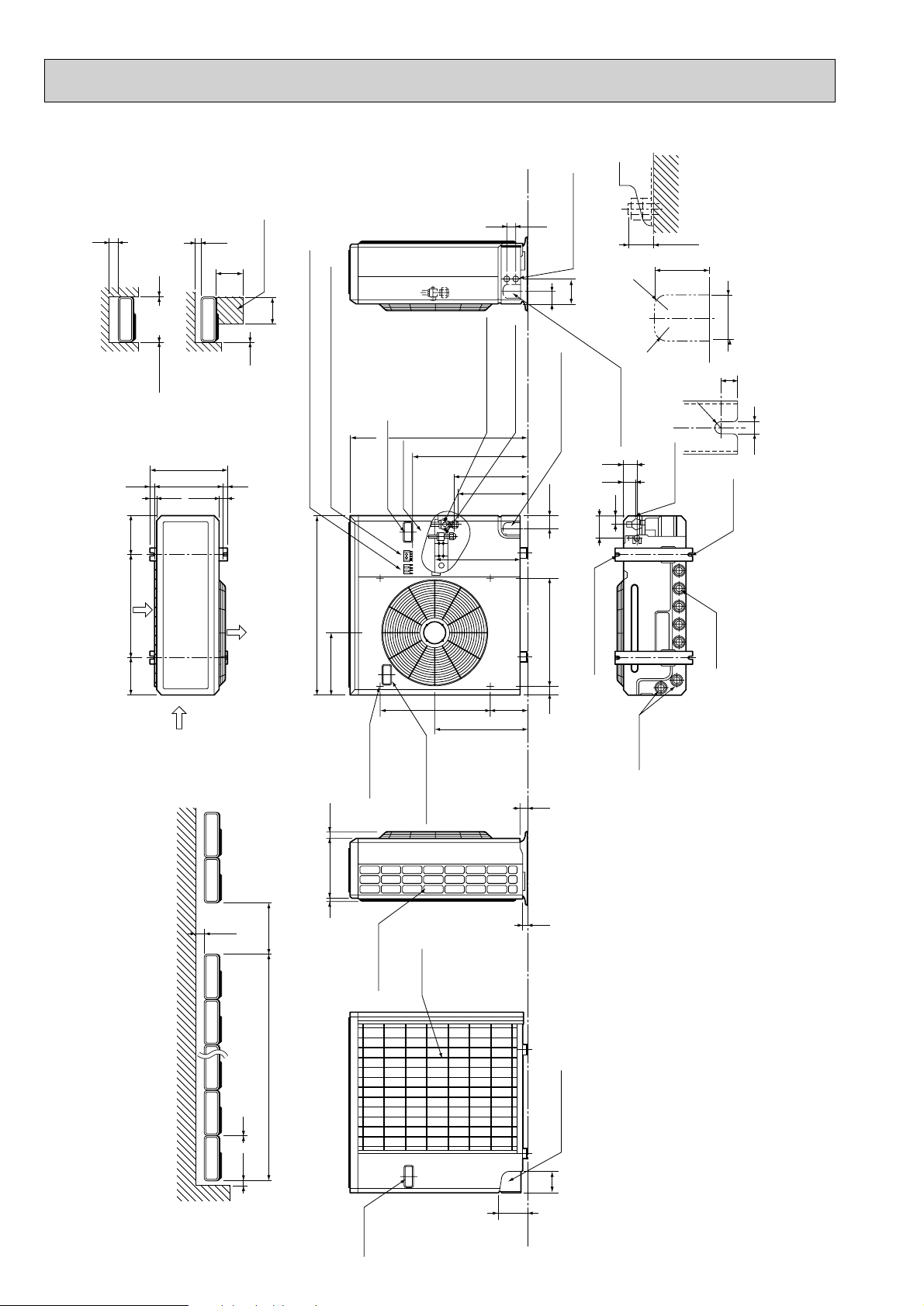
Service space
Front opening
Handle
for moving
138
95
Rear piping hole
23
33
Rear fresh
air intake
Side air intake
7 24(1)295(11-5/8)
Outlet guide
installation hole
302
Air intake
Air intake
Air outlet
870(34-1/4)
185
(7-9/32)
185
(7-9/32)
500(19-11/16)
330(13)
362(14-1/4)
1715
39.5 27.5
Terminal block for indoor and outdoor unit connection
Terminal block for power line and Ground terminal
Handle for moving
179 524
441
337
352
403
553
850(33-7/16)
40 60524
Service panel
Refrigerant-pipe flared
connection [15.88 5/8F
Refrigerant-pipe flared
connection [9.52 3/8F
Knock out hole
for front piping
(refrigerant,drainage
and wiring)
Knock out hole
for right piping
(refrigerant,drainage
and wiring)
R
20
R20
60
120
4553
25 max.
Knock out holes for
power line 2-[27
Standard bolt length
65
Front right piping holes-
detail figures
80
17
42
45
12
R6
104
33
Bottom
piping hole
2-U-shaped
notched
holes
Drain hole
Drain hole
2-12o23 Oval holes
(standard bolt M10)
Handle for moving
PUH-2.5VKA2·UK,PUH-3VKA2·UK,PUH-3YKA2·UK Unit : mm (inch)
PUH-2.5NKA1·UK,PUH-3NKA1·UK
6
Page 7
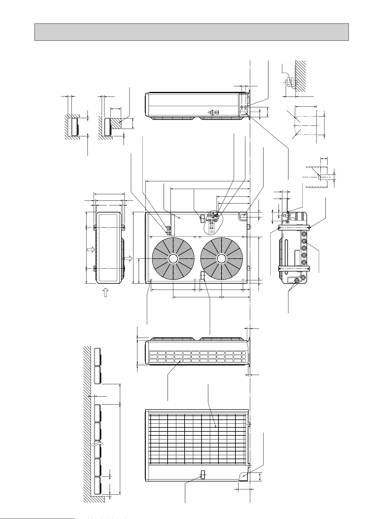
PUH-4YKSA2·UK,PUH-4TKSA1·UK Unit : mm (inch)
4553
300
Note:Allow adequate
upper clearance
10
Front opening
10
Outdoor Unit-Necessary surrounding clearance
1715
185
(7-9/32)
100
500
Service space
500
10
Terminal block for
indoor and outdoor
unit connection
362(14-1/4)
330(13)
39.5 27.5
Terminal block for power line
and Ground terminal
Service panel
Handle
for moving
Refrigerant-pipe flared
1258(49-1/2)
959
Knock out holes for
60
connection [19.05 3/4F
Refrigerant-pipe flared
connection [9.52 3/8F
Knock out hole
for front piping
403
382
power line 2-[27
120
(refrigerant,drainage
and wiring)
104
R20
20
R
Knock out hole
for right piping
(refrigerant,
57
52
Bottom
39
drainage and wiring)
25 max.
80
R6
piping hole
2-U-shaped
Standard bolt length
65
Front right piping holes-
detail figures
17
12
notched
holes
Air intake
500(19-11/16)
185
(7-9/32)
Air intake
300
1000For 10 units or less
The upper side must be open.
870(34-1/4)
302
Air outlet
Outlet guide
installation hole
7 24(1)295(11-5/8)
52461
Side air intake
585
Handle for moving
Rear fresh
air intake
345
2-12o23 Oval holes
(standard bolt M10)
83 524
40 60524
Drain hole
33
23
Drain hole
Outdoor Unit-Necessary surrounding clearance
(Concentrated installation)
150 10
Handle
for moving
Rear piping hole
95
138
7
Page 8
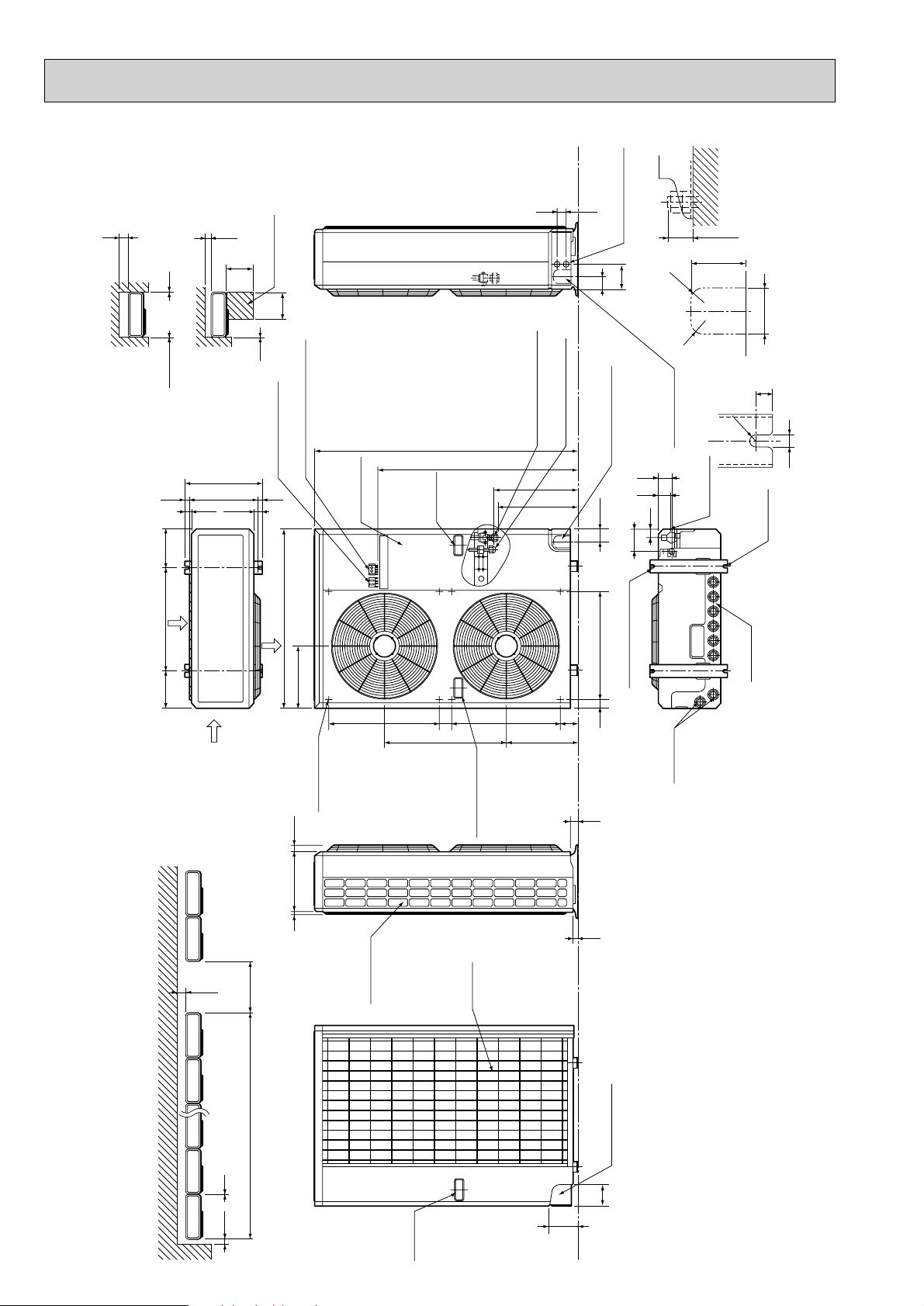
PUH-5YKSA2·UK,PUH-6YKSA2·UK Unit : mm (inch)
150 10
1000For 10 units or less
300
Outdoor Unit-Necessary surrounding clearance
(Concentrated installation)
Outdoor Unit-Necessary surrounding clearance
The upper side must be open.
Handle
for moving
138
95
Rear piping hole
23
33
Rear fresh
air intake
Side air intake
7 24(1)345(13-9/16)
Outlet guide
installation hole
352
Air intake
Air intake
Air outlet
970(38-3/16)
185
(7-9/32)
185
(7-9/32)
600(23-5/8)
380(14-31/32)
412(16-1/4)
1715
39.5 27.5
Terminal block for
indoor and outdoor
unit connection
Terminal block for power line
and Ground terminal
300
10
10
10
Note:Allow adequate
upper clearance
150
500
500
Service space
Handle for moving
52461
585
83 524
345
382
403
959
1258(49-1/2)
90 60524
Service panel
Handle
for moving
Refrigerant-pipe flared
connection [19.05 3/4F
Refrigerant-pipe flared
connection [9.52 3/8F
Knock out hole
for front piping
(refrigerant,drainage
and wiring)
Knock out hole
for right piping
(refrigerant,
drainage and wiring)
R
20
R20
60
120
4553
25 max.
Knock out holes for
power line 2-[27
Standard bolt length
65
Front right piping holes-
detail figures
80
17
52
57
12
R6
104
39
Bottom
piping hole
2-U-shaped
notched
holes
Drain hole
Drain hole
2-12o23 Oval holes
(standard bolt M10)
Front opening
8
Page 9
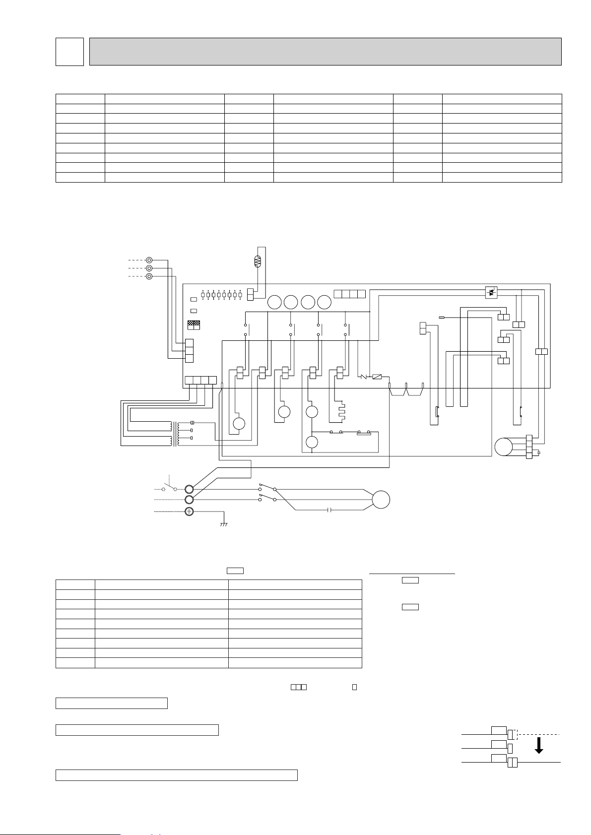
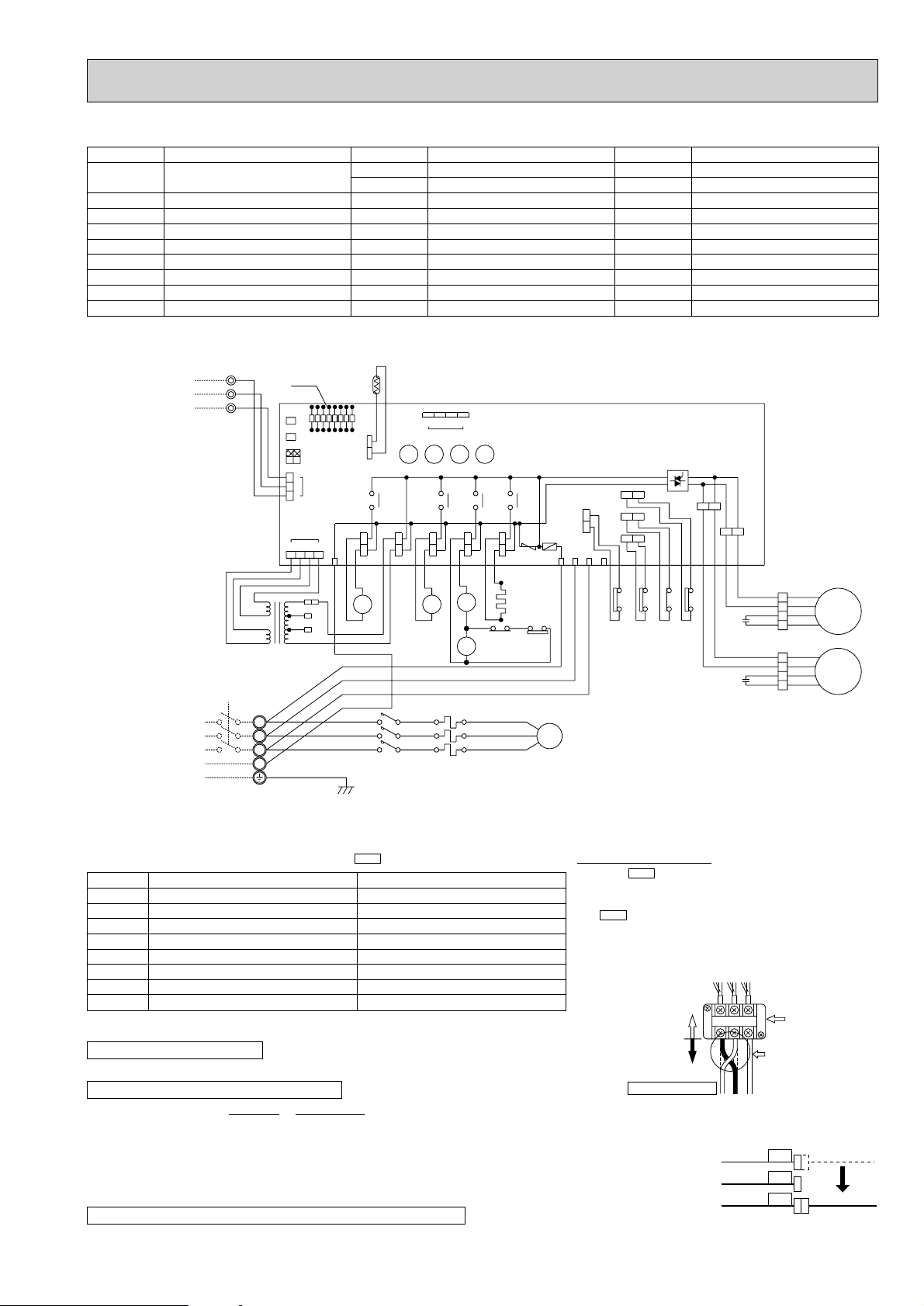
5 WIRING DIAGRAM
8
7
6
2
1
5
GRY
GRY
GRY
63H2
X16
X16
X16
VLT
VLT
RED
N
BLU
1
230V
ORN
RED
4
3
WHT
RED
ORN
BLU
WHT
WHT
WHT
2
X11X12X13
1234
CN2
63H1
BRN
3
1
X13X14
X14
SV
RED
RED
21R
21S4
21
S4
BLU
BLU
MF
ORN
C1
RED
52C
L1/1
L3/5
T3/6
T1/2
BLU
WHT
BLU
C2
S
C
MC
R
63H1
BRN
BRN
GRN/YLW
T
ORN
YLW
1
2
TB3
L
RED AC12.3V
BRN AC12.3V
RED
YLW
BLU
BLU
RED
240V
220V
4
1234
CN4T
CN3
2
3
12
SW3
SW2
O.B
SW1
TO INDOOR UNIT
CONNECTING WIRES
DC 12V (polar)
TB1
POWER SUPPLY
~(1PHASE)
220—240V 50Hz
ON
OFF
LD7
LD1
LD2
LD3
LD4
LD5
LD6
LD8
F
5
RT
X11X12
CN4
TRF 52C
WHT
WHT
GRY
GRY
A1
A2
52C
HC
CH
ZNR
R/1 S/2 T/3
BLU BLU
YLW
YLW
YLW
YLW
BLU
FC
26C
63H2
51CM
MF2
MF1
PUH-1.6VKA3·UK
SYMBOL
HC
C1
C2
FC<O.B
>
F<O.B
21S4
21R
LD1~LD8
CRANKCASE HEATER
FAN MOTOR CAPACITOR
COMPRESSOR CAPACITOR
>
FAN CONTROLLER
FUSE(6A
4-WAY VALVE SOLENOID COIL
BYPASS VALVE SOLENOID COIL
LED(CHECK, SERVICE)
NAME
)
SYMBOL
MC
MF
O.B
SW1·2·3<O.B
T
TB1,3
RT
X11<O.B>
COMPRESSOR MOTOR(INNER THERMOSTAT)
NAME
FAN MOTOR (INDOOR THERMOSTAT)
OUTDOOR CONTROLLER BOARD
>
SELECT SWITCH(CHECK,SERVICE)
TRANSFORMER
TERMINAL BLOCK
OUTDOOR COIL THERMISTOR
(
0˚C/15kΩ,25˚C/5.4kΩ
)
HC RELAY
SYMBOL
X12<O.B
X13<O.B
X14<O.B
X16
ZNR<O.B>
52C
63H1
63H2
>
COMPRESSOR RELAY
>
21S4 RELAY
>
21R RELAY
HIGH PRESSURE RELAY
VARISTOR
COMPRESSOR CONTACTOR
HIGH PRESSURE SWITCH
PROTECTIVE HIGH PRESSURE SWITCH
NAME
Main functions of LED
LED No.
NOTES : 1. If the operation of the protection device stops to function. then check the display flashes.
CAUTIONS FOR SERVICING
●
Connect the lead wires according to the color indication of sticker on the compressor terminal.
CAUTIONS FOR POWER SUPPLY WIRING
●
Since LD8 lights when normal power is furned ”ON”, check the power supply with the ON or OFF LD8.
w
Since the transformer (T) is connected with 240V power, if 220V or 230V power is used,
change the wiring connection in the following procedure.
CAUTION FOR INDOOR AND OUTDOOR CONNECTING WIRES
●
Since the indoor and outdoor connecting wires has polarity, make sure to connect the same terminal numbers (1,2,3) for indoor and outdoor units.
LD1
LD2
LD3
LD4
LD5
LD6
LD7
LD8
Compressor indoor command
Heating indoor command
63H1 ON
Compressor ON
Outdoor fan ON
4-way valve ON
Bypass valve ON
Crankcase heater ON
(
when both Nos.1 and 2 of are ”OFF”
Output display (light
2. Symblos used in wiring diagram above are.
)
SW3
Pipe temp. sensor short/open
)
Check display (flash
—
—
—
—
How to use SW1 and 2
●
)
Pressing erases the past check contents loaded on the
microcomputer.
●
The output display (light) remains lit during operation but
pressing displays the past check contents in flashing
mode. Pressing the switch again returns to output display
(light).
26C functions
RT overheat protecyion
Defective input
/:Terminal block :Connector :PC board insertion tab.
SW1
SW2
wWhen power supply is 220V
YELLOW
ORANGE
RED
240V
230V
220V
WHITE
9
Page 10
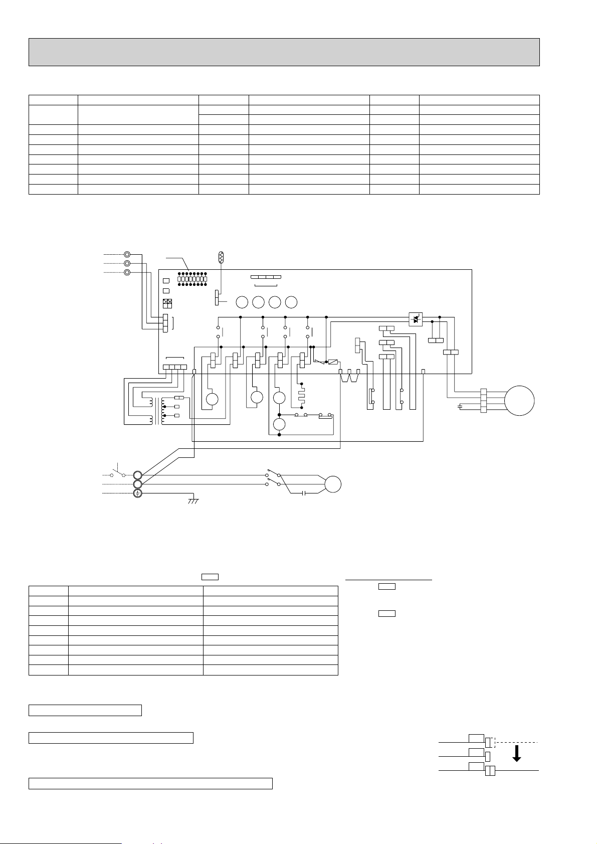
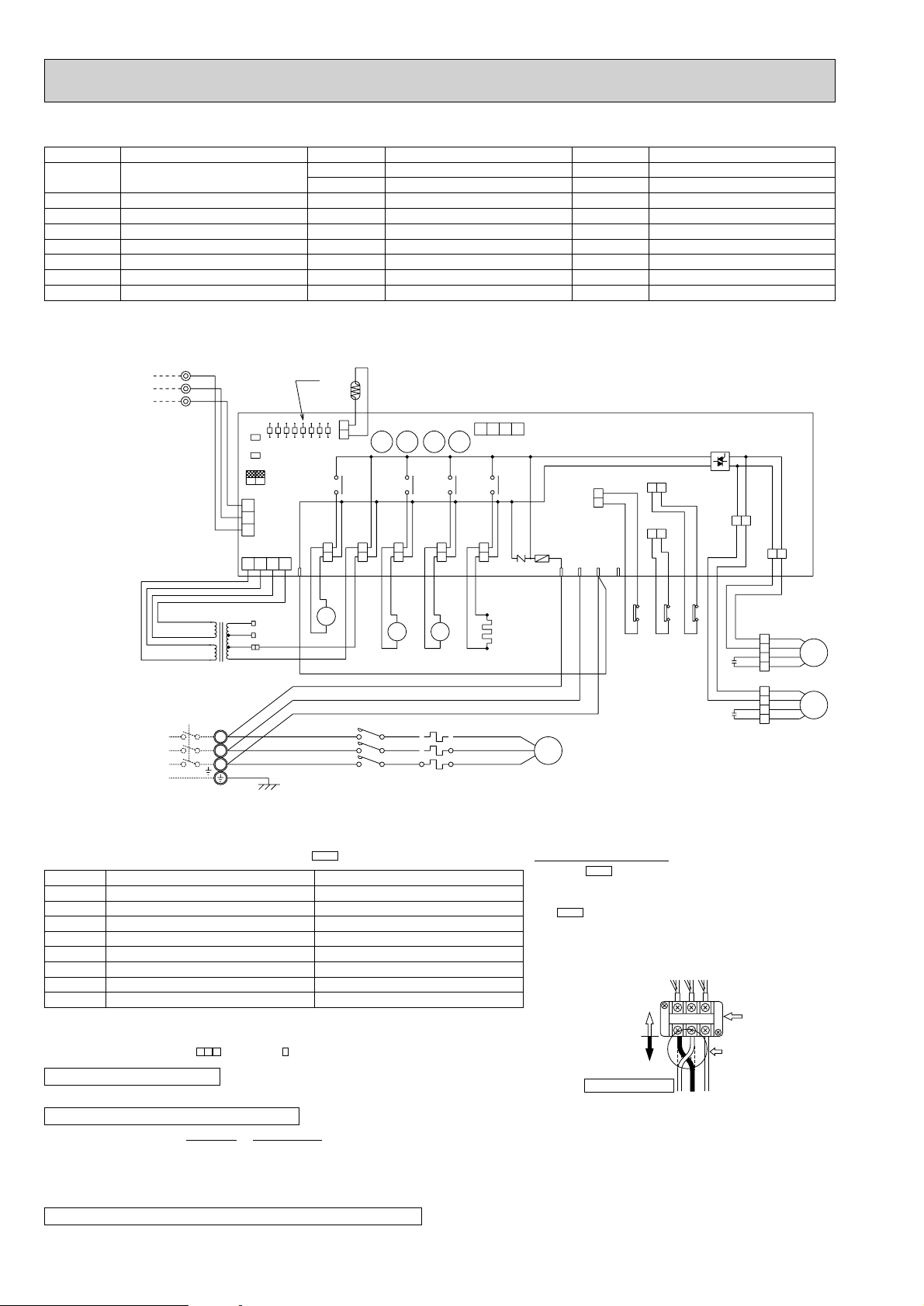
PUH-2VKA2·UK,PUH-2.5VKA2·UK,PUH-3VKA2·UK
5
1
2
6
8
7
GRY
GRY
63H2
X16
X16
GRY
A2
52C
A1
GRY
GRY
VLT
VLT
X16
63H2
N
L
TB1
RED
BLU
RED
BLU
GRN/YLW
52C
RED
C2
BLU
BLUBLU
5
MF2
RED
LED
O.B
LD8
LD7
LD6
LD5
LD4
LD3
LD2
63H1
YLW
YLW
YLW
YLW
BRN
BRN
HC
WHT
WHT
BLU
BLU
RED
RED
S
C
R
BLU
WHT
BLU
T2/6
T1/2
L3/5
L1/1
WHT
WHT
220V
230V
240V
RED
ORN
YLW
T
AC12.3V
AC
12.3V
BRN
BRN
RED
RED
C1
ORN
RED
BLU
WHT
ORN
BLU
WHT
F.C
MF1
R
ST
26C
63H1
51CM
F
ZNR
CH52C21S4TRFSV
X11X12X13X14
4
123
CN4T
4
1234
CN4
TH
LD1
CN2
CN3
1
2
3
12
ON
OFF
SW3
SW2
SW1
TB3
BRN
ORN
YLW
3
2
1
POWER SUPPLY
~(1PHASE)
220—240V 50Hz
TO INDOOR UNIT
CONNECTING WIRES
DC 12V
MF
1
2
4
3
MC
21R
21
S4
X11X12X13X14
SYMBOL
CN3(O.B
)
CN4T(O.B
HC
C1
C2
)
FC(O.B
)
F(O.B
LD1-LD8(O.B
CONNECTOR (CONNECTING)
WIRES INDOOR/OUTDOOR
)
CONNECTOR(TRANSFORMER)
CRANKCASE HEATER
FAN MOTOR CAPACITOR
RUN CAPACITOR FOR MC
FAN CONTROLLER
FUSE(6A
)
LED(CHECK,SERVICE)
NAME
)
SYMBOL
MC
MF
O.B
21R
SW1·2·3(O.B
T
TB1,3
TH
X11(O.B
)
COMPRESSOR
FAN MOTOR
OUTDOOR CONTROLLER BOARD
BYPASS VALVE SOLENOID COIL
)
SELECT SWITCH(CHECK,SERVICE)
TRANSFORMER
TERMINAL BLOCK
OUTDOOR COIL THERMISTOR
CRANKCASE HEATER RELAY
NAME
SYMBOL
X12(O.B
X13(O.B
X14(O.B
)
)
)
X16
ZNR<O.B>
21S4
52C
63H1
63H2
COMPRESSOR RELAY
NAME
SOLENOID COIL RELAY
SOLENOID COIL RELAY
HIGH PRESSURE RELAY
SURGE ABSORBER
4-WAY VALVE SOLENOID COIL
CONPRESSOR CONTACTOR
CONTROL HIGH PRESSURE SWITCH
PROTECTIVE HIGH PRESSURE SWITCH
Main functions of LED
LED No.
LD1
LD2
LD3
LD4
LD5
LD6
LD7
LD8
Compressor indoor command
Heating indoor command
63H1 ON
Compressor ON
Outdoor fan ON
4-way valve ON
Bypass valve ON
Crankcase heater ON
NOTE : If the operation of the protection device stops to function. then check the display flashes.
CAUTIONS FOR SERVICING
●
Connect the lead wires according to the color indication of sticker on the compressor terminal.
CAUTIONS FOR POWER SUPPLY WIRING
●
Since LD8 lights when normal power is furned ”ON”, check the power supply with the ON or OFF LD8.
w
Since the transformer (T) is connected with 240V power, if 220V or 230V power is used,
(
when both Nos.1 and 2 of are ”OFF”
Output display (light
change the wiring connection in the following procedure.
CAUTION FOR INDOOR AND OUTDOOR CONNECTING WIRES
●
Since the indoor and outdoor connecting wires has polarity, make sure to connect the same terminal numbers (1,2,3) for indoor and outdoor units.
10
)
SW3
Pipe sensor short/open
TH overheat protecyion
Defective input
)
Check display (flash
—
—
—
—
—
)
How to use SW1 and 2
●
Pressing erases the past check contents loaded on the
microcomputer.
●
The output display (light) remains lit during operation but
pressing displays the past check contents in flashing
mode. Pressing the switch again returns to output display
(light).
SW1
SW2
wWhen power supply is 220V
YELLOW
ORANGE
RED
240V
230V
220V
WHITE
Page 11
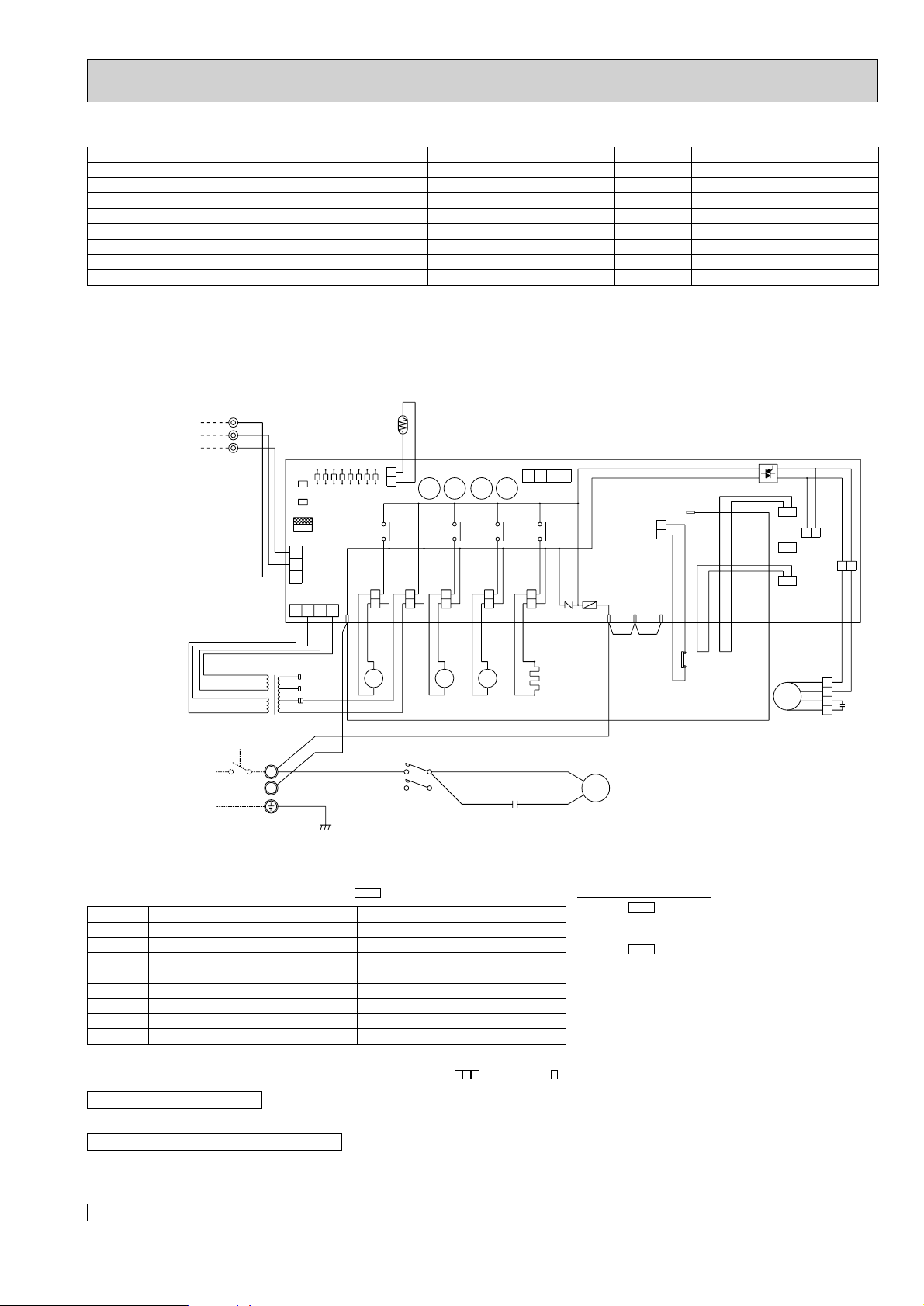
PUH-2NKA1·UK,PUH-2.5NKA1·UK,PUH-3NKA1·UK
SYMBOL
HC
C1
C2
FC<O.B>
F<O.B>
LD1~LD8
MC
MF
TO INDOOR UNIT
CONNECTING WIRES
DC 12V (polar)
POWER SUPPLY
~(1PHASE)
220V—60Hz
CRANKCASE HEATER
FAN MOTOR CAPACITOR
COMPRESSOR CAPACITOR
FAN CONTROLLER
FUSE(6A)
LED(CHECK,SERVICE)
COMPRESSOR MOTOR(INNER THERMOSTAT)
FAN MOTOR(INNER THERMOSTAT)
1
2
3
TB3
BRN AC12.3V
RED AC12.3V
NAME
YLW
ORN
BRN
TB1
GRN/YLW
SYMBOL
O.B
RT
SW1·2·3(OB)
T
TB1,3
X11(O.B
X12(O.B
X13(O.B
RT
O.B
SW1
SW2
LD1
SW3
OFF
ON
12
3
2
CN3
1
CN4T
YLW
240V
ORN
230V
RED
220V
T
L
N
RED
BLU
RED
BLU
LD7
LD2
LD3
LD4
LD5
LD6
LD8
4
1234
SV
RED
RED
21R
L1/1
L3/5
OUTDOOR CONTROLLER BOARD
OUTDOOR COIL THERMISTOR
(
0˚C/15kΩ,25˚C/5.4kΩ
SELECT SWITCH(CHECK,SERVICE)
TRANSFORMER
TERMINAL BLOCK
)
HC RELAY
)
COMPRESSOR RELAY
)
SOLENOID COIL RELAY
CN2
X14
WHT
WHT
X13X14
21S4
TRF 52C
BLU
BLU
21
S4
52C
T1/2
T3/6
GRY
BLU
WHT
BLU
NAME
X11X12
GRY
A1
52C
A2
SYMBOL
63H1
)
SOLENOID COIL RELAY
)
VARISTOR
4-WAY VALVE SOLENOID COIL
BYPASS VALVE SOLENOID COIL
COMPRESSOR CONTACTOR
HIGH PRESSURE SWITCH
5
BRN
BRN
YLW
YLW
YLW
63H1
)
ZNR(O.B
21S4
21R
52C
63H1
1234
CN4
X11X12X13
F
ZNR
X14(O.B
CH
WHT
WHT
RED
C2
HC
R/1 S/2 T/3
R
C
MC
S
BLU BLU
NAME
FC
26C
MF2
63H2
MF1
51CM
BLU
YLW
MF
BLU
WHT
RED
ORN
BLU
WHT
4
3
RED
2
C1
1
ORN
Main functions of LED
LED No.
LD1
LD2
LD3
LD4
LD5
LD6
LD7
LD8
Output display (light
Compressor indoor command
Heating indoor command
63H1 ON
Compressor ON
Outdoor fan ON
4-way valve ON
Bypass valve ON
Crankcase heater ON
(
when both Nos.1 and 2 of are ”OFF”
SW3
)
Pipe temp. sensor short/open
RT overheat protecyion
Defective input
)
Check display (flash
—
—
—
—
—
How to use SW1 and 2
●
)
Pressing erases the past check contents loaded on the
microcomputer.
●
The output display (light) remains lit during operation but
pressing displays the past check contents in flashing
mode. Pressing the switch again returns to output display
(light).
SW1
SW2
NOTES : 1. If the operation of the protection device stops to function. then check the display flashes.
2. Symblos used in wiring diagram above are. /:Terminal block :Connector :PC board insertion tab.
CAUTIONS FOR SERVICING
●
Connect the lead wires according to the color indication of sticker on the compressor terminal.
CAUTIONS FOR POWER SUPPLY WIRING
●
Since LD8 lights when normal power is furned ”ON”, check the power supply with the ON or OFF LD8.
w
Since the transformer (T) is connected with 240V power, if 220V or 230V power is used,
change the wiring connection in the following procedure.
CAUTION FOR INDOOR AND OUTDOOR CONNECTING WIRES
●
Since the indoor and outdoor connecting wires has polarity, make sure to connect the same terminal numbers (1,2,3) for indoor and outdoor units.
11
Page 12
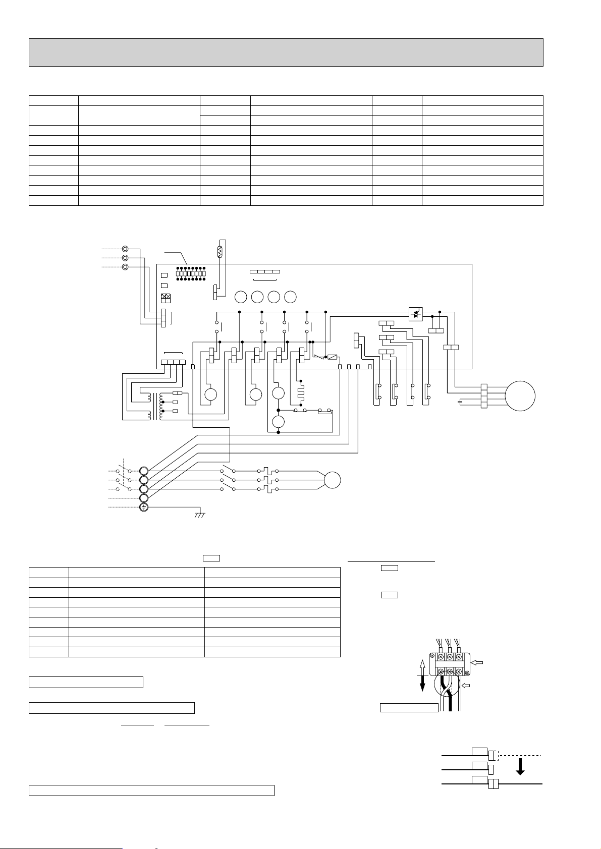
PUH-3YKA2·UK
L1L2L3
Power line reconnoction procedure
In case of reverse rotation
Unit side
wiring
Outdoor unit
terminal
Field wiring
Change thie side
Change 2 out of 1.
2 and 3.
(This example shows
reconnection of 1
and 2.)
123
5
1
2
6
8
7
A2
A1
GRY
GRY
52C
GRY
GRY
GRY
63H2
X16
X16
63H2
26C
YLW
YLW
N
L3
L2
L1
TB1
WHT
RED
RED
WHT
BLK
BLU
BLK
GRN/YLW
LED
O.B
LD8
LD7
LD6
LD5
LD4
LD3
LD2
95
96
X1651C63H1
VLT
VLT
ORN
ORN
BRN
BRN
HC
WHT
WHT
BLU
BLU
RED
RED
W
V
U
BLU
WHT
RED
51C
T3/6
T2/4
T1/2
52C
L3/5
L2/3
L1/1
WHT
WHT
220V
230V
240V
RED
ORN
YLW
T
AC12.3V
AC
12.3V
BRN
BRN
RED
RED
C
ORN
RED
BLU
WHT
ORN
RED
BLU
WHT
F.C
MF1
MF2
R
ST
26C
63H1
51C
5
F
ZNR
CH52C21S4TRFSV
X11X12X13X14
4
123
CN4T
4
1234
CN4
TH
LD1
CN2
CN3
1
2
3
12
ON
OFF
SW3
SW2
SW1
TB3
BRN
ORN
YLW
3
2
1
POWER SUPPLY
3N~(3PHASE 4WIRES)
380/220—415/240V 50Hz
TO INDOOR UNIT
CONNECTING WIRES
DC 12V
MF
1
2
4
3
MC
21R
21
S4
X11X12X13X14
SYMBOL
CN3<O.B
CN4T<O.B
C
FC<O.B
F<O.B
HC
LD1-LD8<O.B
MC
MF
>
CONNECTOR (CONNECTING
WIRES INDOOR/OUTDOOR)
>
CONNECTOR (TRANSFORMER)
FAN MOTOR CAPACITOR
>
FAN CONTROLLER
>
FUSE(6A
CRANKCASE HEATER
>
LED(CHECK,SERVICE)
COMPRESSOR
FAN MOTOR
NAME
)
SYMBOL
O.B
SW1·2·3<O.B
T
TB1,3
TH
X11<O.B
X12<O.B
X13<O.B
X14<O.B
X16
OUTDOOR CONTROLLER BOARD
NAME
>
SELECT SWITCH(CHECK,SERVICE)
TRANSFORMER
TERMINAL BLOCK
OUTDOOR COIL TERMISTOR
>
CRANKCASE HEATER RELAY
>
COMPRESSOR RELAY
>
SOLENOID COIL RELAY
>
SOLENOID COIL RELAY
HIGH PRESSURE RELAY
SYMBOL
ZNR<O.B>
21R
21S4
26C
51C
52C
63H1
63H2
SURGE ABSORBER
NAME
BYPASS VALVE SOLENOID COIL
4-WAY VALVE SOLENOID COIL
THERMAL SWITCH
THERMAL RELAY
COMPRESSOR CONTACTOR
CONTROL HIGH PRESSURE SWITCH
PROTECTIVE HIGH PRESSURE SWITCH
Main functions of LED
LED No.
LD1
LD2
LD3
LD4
LD5
LD6
LD7
LD8
NOTE : If the operation stops to function of the protection device, the check display flashes.
CAUTIONS FOR SERVICING
●
Connect the lead wires according to the color indication of sticker on the compressor terminal.
CAUTIONS FOR POWER SUPPLY WIRING
●
Making wiring connection in anti-phase or missing phase “A2” or “A3” causes the protection device incorporated in the
Output display (light
Compressor indoor command
Heating indoor command
63H1 ON
Compressor ON
Outdoor fan ON
4-way valve ON
Bypass valve ON
Crankcase heater ON
microcomputer to function resulting in LD1 or LD2 shown in the table above to flash and prevents the compressor
operation. If phase “A1” or “N” is missing it causes all displays to go out. Under normal condition LD8 light when power
is turned “ON”. If anti-phase connection is to be used, change connections of 2 out of 3 power lines (field wiring side)
contained in the power supply terminal block (TB1) of the outdoor unit as shown at the right upper.
w
Since the transformer (T) is connected with 240V power, if 220V or 230V power is used, change the wiring connection
in the following procedure.
CAUTION FOR INDOOR AND OUTDOOR CONNECTING WIRES
●
Since the indoor and outdoor connecting wires has polarity, make sure to connect the same terminal numbers (1,2,3) for indoor and outdoor units.
12
(
when both Nos.1 and 2 of are “OFF”
)
SW3
Check display (flash
Anti-phase detect
Missing-phase detect
Pipe sensor short/open
51C functions
26C functions
TH overheat protection
Defective input
)
)
—
How to use SW1 and 2
●
Pressing erases the past check contents loaded on the
microcomputer.
●
The output display (light) remains lit during operation but
pressing displays the past check contents in flashing
mode. Pressing the switch again returns to output display
(light).
SW1
SW2
wWhen power supply is 220V
YELLOW
ORANGE
RED
240V
230V
220V
WHITE
Page 13
PUH-4YKSA2·UK
SYMBOL
CN3<O.B
CN4T<O.B
C1,2
FC<O.B
F<O.B
HC
LD1-LD8<O.B
MC
MF1,2
POWER SUPPLY
3N~(3PHASE 4WIRES)
380/220 — 415/240V 50Hz
>
CONNECTOR (CONNECTING
WIRES INDOOR/OUTDOOR)
>
CONNECTOR (TRANSFORMER)
FAN MOTOR CAPACITOR
>
FAN CONTROLLER
>
FUSE(6A
CRANKCASE HEATER
>
LED(CHECK,SERVICE)
COMPRESSOR
FAN MOTOR
TO INDOOR UNIT
CONNECTING WIRES
DC 12V
)
1
2
3
TB3
RED
NAME
YLW
ORN
BRN
RED
BRN
BRN
AC
12.3V
AC12.3V
TB1
L1
L2
L3
N
T
O.B
SW1
SW2
SW3
4
YLW
GRN/YLW
12
3
2
1
ORN
RED
LED
OFF
ON
CN3
CN4T
LD1
240V
230V
220V
LD2
123
LD3
LD6
LD5
LD4
CN2
4
RED
WHT
WHT
RED
WHT
BLK
BLU
RED
WHT
BLK
SYMBOL
O.B
SW1·2·3<O.B
T
TB1,3
TH
X11<O.B
X12<O.B
X13<O.B
X14<O.B
X16
TH3
LD8
LD7
TRFSV
RED
21R
L1/1
L2/3
L3/5
52C
OUTDOOR CONTROLLER BOARD
NAME
>
SELECT SWITCH(CHECK,SERVICE)
TRANSFORMER
TERMINAL BLOCK
OUTDOOR COIL TERMISTOR
>
CRANKCASE HEATER RELAY
>
COMPRESSOR RELAY
>
SOLENOID COIL RELAY
>
SOLENOID COIL RELAY
HIGH PRESSURE RELAY
1234
CN4
X11X12X13X14
X11X12X13X14
63H2
63H1
ZNR
F
RST
5
BLU
21S4
BLU
S4
52C
CH
GRY
GRY
WHT
WHT
A1
21
52C
X16
51C
A2
GRY
7
8
T1/2
T2/4
T3/6
HC
GRY
6
2
X16
63H2
GRY
RED
U
WHT
V
BLU
MC
W
SYMBOL
ZNR<O.B>
21R
21S4
26C
51C
52C
63H1
63H2
26C
51C
ORN
ORN
BRN
BRN
SURGE ABSORBER
NAME
BYPASS VALVE SOLENOID COIL
4-WAY VALVE SOLENOID COIL
THERMAL SWITCH
THERMAL RELAY
COMPRESSOR CONTACTOR
CONTROL HIGH PRESSURE SWITCH
PROTECT HIGH PRESSURE SWITCH
F.C
MF2
MF1
YLW
VLT
YLW
VLT
96
1
X16
26C51C63H1
5
95
WHT
WHT
3
BLU
BLU
4
RED
RED
MF1
2
ORN
WHT
BLU
BRN
YLW
ORN
1
WHT
3
BLU
4
RED
MF2
2
ORN
1
C1
C2
Main functions of LED
LED No.
LD1
LD2
LD3
LD4
LD5
LD6
LD7
LD8
Output display (light
Compressor indoor command
Heating indoor command
63H1 ON
Compressor ON
Outdoor fan ON
4-way valve ON
Bypass valve ON
Crankcase heater ON
(
when both Nos.1 and 2 of are “OFF”
SW3
)
Anti-phase detect
Missing-phase detect
Pipe sensor short/open
51C functions
26C functions
TH overheat protection
Defective input
NOTE : If the operation stops to function of the protection device, the check display flashes.
CAUTIONS FOR SERVICING
●
Connect the lead wires according to the colo indication of sticker on the compressor terminal.
CAUTIONS FOR POWER SUPPLY WIRING
●
Making wiring connection in anti-phase or missing phase “A2” or “A3” causes the protection device incorporated in the
microcomputer to function resulting in LD1 or LD2 shown in the table above to flash and prevents the compressor
operation. If phase “A1” or “N” is missing it causes all displays to go out. Under normal condition LD8 light when power
is turned “ON”. If anti-phase connection is to be used, change connections of 2 out of 3 power lines (field wiring side)
contained in the power supply terminal block (TB1) of the outdoor unit as shown at the right upper.
w
Since the transformer (T) is connected with 240V power, if 220V or 230V power is used, change the wiring connection
in the following procedure.
)
Check display (flash
—
How to use SW1 and 2
●
)
Pressing erases the past check contents loaded on the
microcomputer.
●
The output display (light) remains during operation but
pressing displays the past check contents in flashing
mode. Pressing the switch again returns to output display
(light).
SW1
SW2
Unit side
wiring
Field wiring
Change thie side
Power line reconnoction procedure
In case of reverse rotation
L1L2L3
Change 2 out of 1.
2 and 3.
(This example shows
reconnection of 1
123
and 2.)
wWhen power supply is 220V
YELLOW
ORANGE
RED
240V
230V
220V
CAUTION FOR INDOOR AND OUTDOOR CONNECTING WIRES
●
Since the indoor and outdoor connecting wires has polarity, make sure to connect the same terminal numbers (1,2,3) for indoor and outdoor units.
Outdoor unit
terminal
WHITE
13
Page 14
PUH-4TKSA1·UK
L3
L2
ORN
RED
GRN/YLW
220V
240V
L1/1
L2/3
L3/5
T1/2
T2/4
T3/6
52C
RED AC12.3V
51C
RED
WHT
BLU
BLK
BLK
F.C.
MF1
95
96
26C51C
26C
5
BRN
BLU
YLW
WHT
C2
4
3
2
1
WHT
BLU
MF2
ORN
BLU
RED
WHTWHT
BLU
C1
4
3
2
1
230V
ORN
BLU
WHT
WHT
X11X12X13
1234
CN2
63H1
BRN3
1
X13X14
X14
SV
RED
RED
21R
21S4
21
S4
BLU
BLU
MF1
ORN
RED
W
V
MC
U
63H1
BRN
BRN
T
LED
ORN
YLW
1
2
TB3
L1
BRN AC12.3V
RED
YLW
WHT
RED
WHT
RED
4
1234
CN4T
CN3
2
3
12
SW3
SW2
O.B
SW1
TO INDOOR UNIT
CONNECTING WIRES
DC 12V (polar)
TB1
POWER SUPPLY
3~(3PHASE)
220V 60Hz
ON
OFF
LD7
LD1
LD2
LD3
LD4
LD5
LD6
LD8
F
RT
X11X12
CN4
TRF 52C
WHT
WHT
GRY
GRY
A1
A2
52C
HC
CH ZNR R S T
ORN
ORN
YLW
YLW
51C
MF2
SYMBOL
CN3<O.B
CN4T<O.B
C1,2
FC<O.B
F<O.B
HC
LD1-LD8
MC
>
CONNECTOR (CONNECTING
WIRES INDOOR/OUTDOOR)
>
CONNECTOR (TRANSFORMER)
FAN MOTOR CAPACITOR
>
FAN CONTROLLER
>
FUSE(6A
CRANKCASE HEATER
LED(CHECK,SERVICE)
COMPRESSOR
NAME
)
SYMBOL
MF1,2
O.B
SW1·2·3<O.B
T
TB1,3
RT
X11<O.B
X12<O.B
X13<O.B
FAN MOTOR
NAME
OUTDOOR CONTROLLER BOARD
>
SELECT SWITCH(CHECK,SERVICE)
TRANSFORMER
TERMINAL BLOCK
OUTDOOR COIL TERMISTOR
>
CRANKCASE HEATER RELAY
>
COMPRESSOR RELAY
>
SOLENOID COIL RELAY
SYMBOL
X14<O.B
ZNR<O.B>
21R
21S4
26C
51C
52C
63H1
>
SOLENOID COIL RELAY
SURGE ABSORBER
BYPASS VALVE SOLENOID COIL
4-WAY VALVE SOLENOID COIL
THERMAL SWITCH
THERMAL RELAY
COMPRESSOR CONTACTOR
HIGH PRESSURE SWITCH
NAME
Main functions of LED
LED No.
LD1
LD2
LD3
LD4
LD5
LD6
LD7
LD8
(
Compressor indoor command
Heating indoor command
63H1 ON
Compressor ON
when both Nos.1 and 2 of are “OFF”
Output display (light
Outdoor fan ON
4-way valve ON
Bypass valve ON
Crankcase heater ON
NOTES : 1. If the operation of the protection device stops to function. then check the display flashes.
2. Symblos used in wiring diagram above are.
/:Terminal block :Connector :PC board insertion tab.
CAUTIONS FOR SERVICING
●
Connect the lead wires according to the colo indication of sticker on the compressor terminal.
CAUTIONS FOR POWER SUPPLY WIRING
●
Making wiring connection in anti-phase or missing phase “A2” or “A3” causes the protection device incorporated in the
microcomputer to function resulting in LD1 or LD2 shown in the table above to flash and prevents the compressor
operation. If phase “A1” or “N” is missing it causes all displays to go out. Under normal condition LD8 light when power
is turned “ON”. If anti-phase connection is to be used, change connections of 2 out of 3 power lines (field wiring side)
contained in the power supply terminal block (TB1) of the outdoor unit as shown at the right upper.
CAUTION FOR INDOOR AND OUTDOOR CONNECTING WIRES
●
Since the indoor and outdoor connecting wires has polarity, make sure to connect the same terminal numbers (1,2,3) for indoor and outdoor units.
14
SW3
)
Anti-phase detect
Missing-phase detect
Pipe sensor short/open
51C functions
26C functions
RT overheat protection
Defective input
)
Check display (flash
—
How to use SW1 and 2
●
)
Pressing erases the past check contents loaded on the
microcomputer.
●
The output display (light) remains during operation but
pressing displays the past check contents in flashing
mode. Pressing the switch again returns to output display
(light).
SW1
SW2
Unit side
wiring
Field wiring
Change thie side
Power line reconnoction procedure
In case of reverse rotation
L1L2L3
123
Outdoor unit
terminal
Change 2 out of 1.
2 and 3.
(This example shows
reconnection of 1
and 2.)
Page 15

PUH-5YKSA2·UK
SYMBOL
MC
MF1,2
C1,2
TH
HC
49C
52C
21S4
21R
T
TO INDOOR UNIT
CONNECTING WIRES
DC 12V
POWER SUPPLY
3N~(3PHASE 4WIRES)
380/220—415/240V 50Hz
COMPRESSOR
FAN MOTOR
FAN MOTOR CAPACITOR
OUTDOOR COIL THERMISTOR
CRANKCASE HEATER
INTERNAL THERMOSTAT FOR MC
COMPRESSOR CONTACTOR
4-WAY VALVE SOLENOID COIL
BYPASS VALVE SOLENOID COIL
TRANSFORMER
NAME
1
2
3
TB3
RED
AC12.3V
YLW
ORN
BRN
RED
AC
12.3V
BRN
BRN
TB1
L1
L2
L3
N
T
O.B
SW1
SW2
SW3
LED
OFF
ON
12
3
2
CN3
1
CN4T
4
YLW
ORN
RED
GRN/YLW
LD1
LD2
123
240V
230V
220V
LD3
SYMBOL
TB1,3
26C
O.B
ZNR<O.B>
F<O.B
FC<O.B
X11<O.B
X12<O.B
X13<O.B
X14<O.B
TH
LD8
LD7
LD6
LD5
LD4
CN2
4
RED
RED
13
52C
21R
14
RED
WHT
WHT
RED
WHT
BLK
BLU
RED
L1/1
WHT
L2/3
BLK
L3/5
TERMINAL BLOCK
NAME
THERMAL SWITCH (DIS.CHARGE)
OUTDOOR CONTROLLER BOARD
SURGE ABSORBER
>
FUSE(6A
>
FAN CONTROLLER
>
CRANKCASE HEATER RELAY
>
COMPRESSOR RELAY
>
SOLENOID COIL RELAY
>
SOLENOID COIL RELAY
CN4
BLU
BLU
21
S4
T1/2
T2/4
T3/6
52C
)
1234
X11X12X13X14
X11X12X13X14
ZNR
F
CH52C21S4TRFSV
GRY
GRY
BLK
BLK
A1
52C
X16
HC
A2
GRY
GRY
7
6
2
X16
8
63H2
GRY
RED
WHT
BLU
63H1
RST
SYMBOL
X16
CN3<O.B
CN4T<O.B
SW1,2,3<O.B
LD1-LD8<O.B
51CM<O.B
63H1
63H2
26C
63H2
51CM
5
BRN
BRN
49C
T1
T2
T3
HIGH PRESSURE RELAY
NAME
>
CONNECTOR (CONNECTING
WIRES INDOOR/OUTDOOR
>
CONNECTOR (TRANSFORMER)
>
SELECT SWITCH (CHECK,SERVICE)
>
LED (CHECK,SERVICE)
>
JUMPER CONNECTOR
CONTROL HIGH PRESSURE SWITCH
PROTECT HIGH PRESSURE SWITCH
F.C
MF2
MF1
BLK
BLK
VLT
VLT
MC
1
26C
X1663H1
5
WHT
WHT
3
BLU
BLU
4
RED
RED
ORN
WHT
BLU
BRN
YLW
2
ORN
1
WHT
3
BLU
4
RED
2
ORN
1
C1
C2
MF1
MF2
Main functions of LED
LED No.
LD1
LD2
LD3
LD4
LD5
LD6
LD7
LD8
Output display (light
Compressor indoor command
Heating indoor command
63H1 ON
Compressor ON
Outdoor fan ON
4-way valve ON
Bypass valve ON
Crankcase heater ON
(
when both Nos.1 and 2 of are “OFF”
SW3
)
Anti-phase detect
Missing-phase detect
Pipe sensor short/open
26C functions
TH overheat protection
Defective input
NOTE : If the operation stops to function of the protection device, the check display flashes.
CAUTION FOR SERVICING
●
Connect the lead wires accordling to the color indication of sticker on the compressor terminal.
CAUTIONS FOR POWER SUPPLY WIRING
●
Making wiring connection in anti-phase or missing phase “A2” or “A3” causes the protection device incorporated in the
microcomputer to function resulting in LD1 or LD2 shown in the table above to flash and prevents the compressor
operation. If phase “A1” or “N” is missing it causes all displays to go out. Under normal condition LD8 light when power
is turned “ON”. If anti-phase connection is to be used, change connections of 2 out of 3 power lines (field wiring side)
contained in the power supply terminal block (TB1) of the outdoor unit as shown at the right upper.
w
Since the transformer (T) is connected with 240V power, if 220V or 230V power is used, change the wiring connection
in the following procedure.
)
Check display (flash
—
—
How to use SW1 and 2
●
)
Pressing erases the past check contents loaded on the
microcomputer.
●
The output display (light) remains lit during operation but
pressing displays the past check contents in flashing
mode. Pressing the switch again returns to output display
(light).
SW1
SW2
Power line reconnoction procedure
In case of reverse rotation
Unit side
wiring
L1L2L3
Field wiring
Change thie side
123
wWhen power supply is 220V
YELLOW
ORANGE
RED
Change 2 out of 1.
2 and 3.
(This example shows
reconnection of 1
and 2.)
240V
230V
220V
CAUTION FOR INDOOR AND OUTDOOR CONNECTING WIRES
●
Since the indoor and outdoor connecting wires has polarity, make sure to connect the same terminal numbers (1,2,3) for indoor and outdoor units.
Outdoor unit
terminal
WHITE
15
Page 16

PUH-6YKSA2·UK
SYMBOL
MC
MF1,2
C1,2
TH
HC
49C
52C
21S4
21R
T
TO INDOOR UNIT
CONNECTING WIRES
DC 12V
POWER SUPPLY
3N~(3PHASE 4WIRES)
380/220—415/240V 50Hz
COMPRESSOR
FAN MOTOR
FAN MOTOR CAPACITOR
OUTDOOR COIL THERMISTOR
CRANKCASE HEATER
INTERNAL THERMOSTAT FOR MC
COMPRESSOR CONTACTOR
4-WAY VALVE SOLENOID COIL
BYPASS VALVE SOLENOID COIL
TRANSFORMER
1
2
3
TB3
RED
AC12.3V
RED
NAME
YLW
ORN
BRN
BRN
BRN
AC
12.3V
TB1
L1
L2
L3
N
SYMBOL
TB1,3
26C
O.B
ZNR<O.B
F<O.B
FC<O.B
X11<O.B
X12<O.B
X13<O.B
X14<O.B
LED
O.B
SW1
SW2
LD1
SW3
OFF
ON
12
3
2
CN3
1
CN4T
4
YLW
240V
ORN
230V
RED
220V
T
GRN/YLW
TH
LD8
LD7
LD6
LD5
LD4
LD3
LD2
CN2
123
4
WHT
RED
RED
13
52C
21R
14
3
5
RED
RED
X15
RED
WHT
BLK
BLU
RED
L1/1
WHT
L2/3
BLK
L3/5
TERMINAL BLOCK
THERMAL SWITCH (DIS,CHARGE)
OUTDOOR CONTROLLER BOARD
>
SURGE ABSORBER
>
FUSE (6A)
>
FAN CONTROLLER
>
CRANKCASE HEATER RELAY
>
COMPRESSOR RELAY
>
SOLENOID COIL RELAY
>
SOLENOID COIL RELAY
CN4
BLU
BLU
WHT
BLU
7
21
X15
S4
8
BLU
T1/2
T2/4
T3/6
52C
NAME
SYMBOL
X15
X16
CN3<O.B
BYPASS VALVE RELAY
NAME
HIGH PRESSURE RELAY
>
CONNECTOR (CONNECTING
WIRES INDOOR/OUTDOOR)
VLT
MC
>
CONNECTOR(TRANSFORMER)
>
SELECT SWITCH(CHECK,SERVICE)
>
LED (CHECK,SERVICE)
>
JUMPER CONNECTOR
CONTROL HIGH PRESSURE SWITCH
PROTECT HIGH PRESSURE SWITCH
F.C
MF2
MF1
VLT
BLK
BLK
1
26C
X1663H1
5
WHT
WHT
3
BLU
BLU
4
RED
RED
2
C1
ORN
WHT
BLU
BRN
C2
YLW
MF1
ORN
1
WHT
3
BLU
4
RED
2
MF2
ORN
1
CN4T<O.B
SW1,2,3<O.B
LD1-LD8<O.B
51CM<O.B
63H1
63H2
1234
X11X12X13X14
63H1
RST
26C
63H2
51CM
5
T1
T2
T3
BRN
BRN
49C
X11X12X13X14
ZNR
F
CH52C21S4TRFSV
GRY
GRY
BLK
BLK
A1
52C
X16
HC
A2
GRY
GRY
6
2
7
X16
63H2
8
GRY
RED
WHT
BLU
Main functions of LED
LED No.
LD1
LD2
LD3
LD4
LD5
LD6
LD7
LD8
Output display (light
Compressor indoor command
Heating indoor command
63H1 ON
Compressor ON
Outdoor fan ON
4-way valve ON
Bypass valve ON
Crankcase heater ON
(
when both Nos.1 and 2 of are “OFF”
SW3
)
Anti-phase detect
Missing-phase detect
Pipe sensor short/open
26C functions
TH overheat protection
Defective input
NOTE : If the operation stops to function of the protection device, the check display flashes.
CAUTION FOR SERVICING
●
Connect the lead wires accordling to the color indication of sticker on the compressor terminal.
CAUTIONS FOR POWER SUPPLY WIRING
●
Making wiring connection in anti-phase or missing phase “A2” or “A3” causes the protection device incorporated in the
microcomputer to function resulting in LD1 or LD2 shown in the table above to flash and prevents the compressor
operation. If phase “A1” or “N” is missing it causes all displays to go out. Under normal condition LD8 light when power
is turned “ON”. If anti-phase connection is to be used, change connections of 2 out of 3 power lines (field wiring side)
contained in the power supply terminal block (TB1) of the outdoor unit as shown at the right upper.
w
Since the transformer (T) is connected with 240V power, if 220V or 230V power is used, change the wiring connection
in the following procedure.
)
Check display (flash
—
—
How to use SW1 and 2
●
)
Pressing erases the past check contents loaded on the
microcomputer.
●
The output display (light) remains lit during operation but
pressing displays the past check contents in flashing
mode. Pressing the switch again returns to output display
(light).
SW1
SW2
Power line reconnoction procedure
In case of reverse rotation
Unit side
wiring
L1L2L3
Field wiring
Change thie side
123
wWhen power supply is 220V
YELLOW
ORANGE
RED
Change 2 out of 1.
2 and 3.
(This example shows
reconnection of 1
and 2.)
240V
230V
220V
CAUTION FOR INDOOR AND OUTDOOR CONNECTING WIRES
●
Since the indoor and outdoor connecting wires has polarity, make sure to connect the same terminal numbers (1,2,3) for indoor and outdoor units.
16
Outdoor unit
terminal
WHITE
Page 17

6 REFRIGERANT SYSTEM DIAGRAM
Indoor unit
Outdoor unit
Indoor
heat
exchanger
Thermistor
TH2
Strainer
Flexible tube
Service
port
Accumulator
Ball valve
Strainer
Compressor
Refrigerant pipe
(option)
19.05A({3/4")
(with heat insulator)
Refrigerant pipe
(option)
9.52A({3/8")
(with heat insulator)
Ball valve
(with service port)
Strainer
Bypass
valve
Restrictor
valve
4-way valve
Oil
separator
Service
port
High pressure
Control switch
Protective high
pressure switch
Outdoor heat exchanger
Thermistor
TH
Capillary tube
PUH-5
....
(O.D.4.0OI.D.2.4-R840)O2
PUH-6
....
(O.D.4.0OI.D.2.4-R1200)O2
Distributor
with
strainer
Restrictor valve
Capillary
tube
Flared
connection
THERMAL
SWITCH
Capillary tube
Indoor unit
Outdoor unit
Indoor
heat
exchanger
Thermistor
(TH2)
Strainer
Flexible tube
Service
port
(check)
Accumulator
Ball valve
Strainer
Compressor
Refrigerant pipe
(option)
19.05A({3/4")
(with heat insulator)
Refrigerant pipe
(option)
9.52A({3/8")
(with heat insulator)
Ball valve
(with service port)
Strainer
Bypass
valve
Restrictor
valve
4-way valve
Oil separator
Service
port
High pressure
Control switch
Protective high
pressure switch
Outdoor heat exchanger
Thermistor
TH3
Capillary
tube
(O.D.3.2OI.D.2.0-R820)O2pcs
Distributor
with
strainer
Restrictor
valve
Capillary
tube
Flared
connection
Refrigerant flow in cooling
Refrigerant flow in heating
Indoor unit
Outdoor unit
Indoor
heat
exchanger
Thermistor
(TH2)
Strainer
Flared
connection
Flexible tube
Service
port
Accumulator
Ball valve
Strainer
Compressor
Refrigerant pipe
(option)
15.88A({5/8")
(with heat insulator)
Refrigerant pipe
(option)
9.52A({3/8")
(with heat insulator)
Ball valve
(with service port)
Strainer
Bypass
valve
Restrictor
valve
4-way valve
Oil separator
Service
port
Control high
pressure switch
Protective high
pressure switch
Outdoor heat exchanger
Thermistor
(RT)
R.V coil
heating ON
cooling OFF
Capillary
tube
PUH-1.6 (O.D.3.2OI.D.1.8-R600)
PUH-2 (O.D.3.2OI.D.2.0-R430)
PUH-2.5 (O.D.4.0OI.D.2.4-R1550)
PUH-3 (O.D.4.0OI.D.2.4-R1070)
Distributor
with
strainer
Restrictor
valve
Capillary
tube
PUH-1.6VKA3·UK,PUH-2VKA2·UK,PUH-2.5VKA2·UK
PUH-3VKA
2
·UK,PUH-3YKA2·UK
PUH-4YKSA2·UK
Unit : mm
PUH-5YKSA2·UK
PUH-6YKSA
2
·UK
17
Page 18

Indoor unit
Outdoor unit
Indoor
heat
exchanger
Thermistor
TH2
Strainer
Flexible tube
Service
port
Accumulator
Ball valve
Strainer
Compressor
Refrigerant pipe
(option)
19.05A({3/4")
(with heat insulator)
Refrigerant pipe
(option)
9.52A({3/8")
(with heat insulator)
Ball valve
(with service port)
Strainer
Bypass
valve
Restrictor
valve
4-way valve
Oil
separator
Service
port
Outdoor heat exchanger
Thermistor
TH
O.D.3.2OI.D.1.2-R1250
(O.D.3.2OI.D.2.0-R820)O2
Distributor
with
strainer
Restrictor valve
Capillary
tube
Flared
connection
Capillary
tube
Capillary
tube
Muffler
Restrictor
valve
Control high
pressure switch
Indoor unit
Outdoor unit
Indoor
heat
exchanger
Thermistor
RT2
Strainer
Flared
connection
Flexible tube
Service
port
(Check)
Accumulator
Ball valve
Strainer
Compressor
Refrigerant pipe
(option)
15.88A({5/8")
(with heat insulator)
Refrigerant pipe
(option)
9.52A({3/8")
(with heat insulator)
Ball valve
(with service port)
Strainer
Bypass
valve
Restrictor
valve
4-way valve
Oil separator
Service
port
(check)
Control high
pressure switch
Outdoor heat exchanger
Thermistor
RT
Muffler
Capillary
tube
Capillary
tube
O.D.4.0OI.D.2.4-R600
O.D.3.2OI.D.1.2-R1250
Distributor
with
strainer
Restrictor
valve
Capillary
tube
PUH-2NKA1·UK
Indoor unit
Outdoor unit
Indoor
heat
exchanger
Thermistor
RT2
Strainer
Flared
connection
Flexible tube
Service
port
(Check)
Accumulator
Ball valve
Strainer
Compressor
Refrigerant pipe
(option)
15.88A({5/8")
(with heat insulator)
Refrigerant pipe
(option)
9.52A({3/8")
(with heat insulator)
Ball valve
(with service port)
Strainer
Bypass
valve
Restrictor
valve
4-way valve
Oil separator
Service
port
(check)
Control high
pressure switch
Outdoor heat exchanger
Muffler
Thermistor
RT
R.V coil
heating ON
cooling OFF
w2
Capillary
tube
Capillary
tube
w1
PUH-2NKA (O.D.3.2OI.D.1.2-R1250)
PUH-2.5NKA (O.D.3.2OI.D.1.2-R3000)
PUH-2NKA (O.D.3.2OI.D.2.0-R430)
PUH-2.5NKA (O.D.4.0OI.D.2.4-R1050)
Distributor
with
strainer
Restrictor
valve
Capillary
tube
w1
w2
Refrigerant flow in cooling
Refrigerant flow in heating
PUH-2.5NKA
1
·UK
PUH-3NKA1·UK
Unit : mm
PUH-4TKSA1·UK
18
Page 19

7 DISASSEMBLY PROCEDURE
PUH-4/5/6YKSA2·UK
OPERATING PROCEDURE PHOTOS
1. Removing the electrical parts
(1)
Remove the 3 screws at the front and 2 screws at the
rear of the top panel.
(2)
Remove the top panel.
(3)
Remove the screw from the panel cover. Unhook the
catches from the side panel and pull the panel cover
toward you to remove.
(4)
Remove the screw from the service panel. Pull down
the service panel to unhook the catches. Pull the
service panel toward you to remove.
Photo 1
Photo 2
Screws
Panel cover
Run capacitor
52C relay
2. Removing the fan motors
(1)
Remove the 3 screws and the front panel.
Open the panel to a 45-degree angle and lift it to
remove. The panel is hooked by 3 catches on the left
side.
(2)
Remove the propeller nuts and the propellers.
(3)
Remove the 3 screws each and the fan motors.
Disconnect the lead connectors.
Screws
Photo 3
Propeller
nut
Motor support
Terminal block
Separator support place
High pressure
switch
Valve bed
Propeller Crankcase heater
19
Page 20

OPERATING PROCEDURE PHOTOS
3. Removing the heat exchanger and the compressor
NOTE :When removing the panels, move them up and down
to unhook catches.
(1)
Remove the rear panel set screws : 2 screws at the
front, 1 screw on the side, and 3 screws at the rear.
(2)
Remove the valve bed.
(3)
Open the rear panel rearward to remove.
(4)
Remove the 4 screws of the right side panel and
remove it.
(5)
Remove the 3 screws of the rear guard and remove it.
(6)
Remove the 4screws of the separator support plate
and remove it.
(7)
Remove the 2 screws of the motor support and
remove it.
(8)
Remove the 5 screws of the valve bed. Lift the valve
bed to unhook the catches on both sides.
(9)
Remove the electrical parts box.
)
(
Disconnect the connectors of the high-pressure
10
switch, crankcase heater, shell thermo, and fan motor.
(11)
Remove the 2 screws of the separator and remove it.
(12)
Remove the 2 screws of the heat exchanger and
remove it.
(13)
Detach the welded points of the pipe.
(14)
Remove the 3 nuts of the compressor and remove it.
(15)
Detach the welded points of the suction pipe and
discharge pipe.
Photo 4
Screws
Screws
Photo 5
Heat exchanger
Accumulator
Photo 6
Charge plug
Ball valve
Accumulator
Accumulator
20
Compressor
Page 21

8 PARTS LIST
No.
Part No.
Part name
Specification
Remarks
Unit
Amount
Wiring
Diagram
Symbol
Recommended
Q'ty
Q'ty/set
PUH-1.6
VKA.UK
VKA1.UK
Price
1
2
3
4
5
6
7
8
9
10
11
12
13
TOP PANEL
F.ST SCREW
FRONT PANEL
FRONT PANEL
FAN GUARD
FAN GUARD
PANEL HANDLE
SERVICE PANEL
SERVICE PANEL
SIDE PANEL
LABEL (MITSUBISHI)
REAR PANEL
PANEL COVER
REAR GUARD
MOTOR SUPPORT
BASE
BASE
VKA3.UK
1
13
1
1
3
1
1
2
1
1
1
1
1
1
13
1
1
3
1
1
2
1
1
1
1
1
R01 A00 641
—
R01 A00 668
S70 020 668
R01 A00 675
S70 001 675
R01 A00 655
R01 A00 661
S70 020 661
R01 A00 662
—
R01 A00 682
R01 A00 658
R01 A00 698
S70 021 130
R01 A00 686
S70 020 686
(ZOO4M203H10)
(DG79R130H01)
(5O10)
STRUCTURAL PARTS
PUH-1.6VKA·UK
PUH-1.6VKA1·UK
PUH-1.6VKA3·UK
111
895
2
7
5
3
4
12 13 6 10
Part numbers that are circled are not shown in the figure.
21
Page 22

STRUCTURAL PARTS
No.
Part No.
Part name
Specification
Remarks
Unit
Amount
Wiring
Diagram
Symbol
Recommended
Q'ty
Q'ty/set
PUH-2
VKA.UK
VKA1.UK
Price
1
2
3
4
5
6
7
8
9
10
11
12
13
TOP PANEL
F.ST SCREW
FRONT PANEL
FRONT PANEL
FAN GUARD
FAN GUARD
PANEL HANDLE
SERVICE PANEL
SERVICE PANEL
SIDE PANEL
LABEL (MITSUBISHI)
REAR PANEL
PANEL COVER
REAR GUARD
MOTOR SUPPORT
MOTOR SUPPORT
BASE
BASE
VKA2.UK
1
13
1
1
3
1
1
2
1
1
1
1
1
1
13
1
1
3
1
1
2
1
1
1
1
1
R01 A00 641
—
R01 A00 668
S70 020 668
R01 A00 675
S70 001 675
R01 A00 655
R01 A00 661
S70 020 661
R01 A00 662
—
R01 A00 682
R01 A00 658
R01 A00 698
S70 021 130
S70 030 130
R01 A04 686
S70 001 686
(ZOO4M203H10)
(DG79R130H01)
(5O10)
NKA1.UK
1
13
1
1
3
1
1
2
1
1
1
1
1
PUH-2VKA·UK
PUH-2VKA1·UK
PUH-2VKA2·UK
PUH-2NKA1·UK
2
7
5
3
4
111
895
12 13 6 10
Part numbers that are circled are not shown in the figure.
22
Page 23

STRUCTURAL PARTS
(Z004M203H10)
(DG79R130H01)
No.
Part No.
Part name
Specification
Remarks
Unit
Amount
Wiring
Diagram
Symbol
Recommended
Q'ty
Q'ty/set
PUH-2.5/3
VKA.UK
YKA.UK
VKA1.UK
YKA1.UK
VKA2.UK
YKA2.UK
Price
1
2
3
4
5
6
7
8
9
10
11
12
13
TOP PANEL
F.ST SCREW
FRONT PANEL
FRONT PANEL
FAN GUARD
FAN GUARD
PANEL HANDLE
SERVICE PANEL
SERVICE PANEL
SIDE PANEL
LABEL (MITSUBISHI)
REAR PANEL
PANEL COVER
REAR GUARD
MOTOR SUPPORT
BASE
BASE
NKA1.UK
1
13
1
1
3
1
1
1
1
1
1
1
1
R01 A00 641
—
R01 A08 668
S70 001 668
R01 A00 675
S70 001 675
R01 A00 655
R01 A08 661
S70 001 661
R01 A08 662
—
R01 A08 682
R01 A00 658
R01 A08 698
S70 030 130
R01 A04 686
S70 001 686
(5O10)
1
13
1
1
3
1
1
1
1
1
1
1
1
1
13
1
1
3
1
1
1
1
1
1
1
1
1
13
1
1
3
1
1
1
1
1
1
1
1
PUH-2.5VKA·UK,PUH-2.5VKA1·UK,PUH-2.5VKA2·UK
PUH-3VKA·UK,PUH-3VKA1·UK,PUH-3VKA2·UK
PUH-3YKA·UK,PUH-3YKA1·UK,PUH-3YKA2·UK
PUH-2.5NKA1·UK
PUH-3NKA
1·UK
7
3
5
1112
895
4
Part numbers that are circled are not shown in the figure.
13 12 6 10
23
Page 24

STRUCTURAL PARTS
No.
Part No.
Part name
Specification
Remarks
Unit
Amount
Wiring
Diagram
Symbol
Recommended
Q'ty
Q'ty/set
PUH-4
YKSA.UK
YKSA1.UK
Price
1
2
3
4
5
6
7
8
9
10
11
12
13
14
TOP PANEL
F.ST SCREW
FRONT PANEL
FRONT PANEL
FAN GUARD
FAN GUARD
FAN GUARD
PANEL HANDLE
SERVICE PANEL
SERVICE PANEL
SIDE PANEL
LABEL (MITSUBISHI)
REAR PANEL
PANEL COVER
REAR GUARD
MOTOR SUPPORT
MOTOR PLATE
BASE
BASE
YKSA2.UK
1
13
1
2
3
1
1
2
1
1
1
1
1
1
TKSA1.UK
1
13
1
2
3
1
1
2
1
1
1
1
1
1
1
13
1
2
3
1
1
2
1
1
1
1
1
1
R01 A00 641
–
R01 A11 668
S70 004 668
R01 A00 675
T7W 001 675
S70 001 675
R01 A00 655
R01 A11 661
S70 004 661
R01 A11 662
–
R01 A11 682
R01 A00 658
R01 A11 698
S70 004 130
–
R01 A10 686
S70 001 686
(ZOO4M203H10)
(DG79G475H01)
(BG02C075H03)
(5O10)
PUH-4YKSA·UK,PUH-4YKSA1·UK,PUH-4YKSA2·UK
PUH-4TKSA1·UK
4
3
5
4
112 13 1127
89
5
Part numbers that are circled are not shown in the figure.
14
24
6
10
Page 25

STRUCTURAL PARTS
No.
Part No.
Part name
Specification
Remarks
Unit
Amount
Wiring
Diagram
Symbol
Recommended
Q'ty
Q'ty/set
PUH-5 PUH-6
YKSA.UK
YKSA1.UK
YKSA
2.UK
YKSA.UK
YKSA
1.UK
YKSA
2.UK
Price
1
2
3
4
5
6
7
8
9
10
11
12
13
14
TOP PANEL
F.ST SCREW
FRONT PANEL
FAN GUARD
PANEL HANDLE
SERVICE PANEL
SERVICE PANEL
SIDE PANEL
LABEL (MITSUBISHI)
REAR PANEL
PANEL COVER
REAR GUARD
MOTOR SUPPORT
MOTOR PLATE
MOTOR PLATE
BASE
1
13
1
2
3
1
1
2
1
1
1
1
1
1
1
13
1
2
3
1
1
2
1
1
1
1
1
1
1
13
1
2
3
1
1
2
1
1
1
1
1
1
1
13
1
2
3
1
1
2
1
1
1
1
1
1
R01 A14 641
—
S70 010 668
S70 001 675
R01 A00 655
R01 A14 661
S70 010 661
R01 A14 662
—
R01 A14 682
R01 A14 658
R01 A14 698
S70 050 130
—
—
S70 010 686
(ZOO4M203H10)
(DG79R130H01)
(DG02C075H03)
(DG02C075H04)
(5O10)
W
W
W
PUH-5YKSA·UK,PUH-5YKSA1·UK,PUH-5YKSA2·UK
PUH-6YKSA·UK,PUH-6YKSA1·UK,PUH-6YKSA2·UK
3
7
2
4
5
4
11213 11
86
9
14
Part numbers that are circled are not shown in the figure.
10
5
25
Page 26

FUNCTIONAL PARTS
PUH-1.6VKA·UK
PUH-1.6VKA
PUH-1.6VKA
1·UK
3·UK
11
13
1047389
14
17
29
1
2
32
15
16
19
20
18
30
31
28
23
24
25
28
5
6
27
2612
26
Page 27

Part numbers that are circled are not shown in the figure.
No.
S70 020 763
W
1
R01 A00 115
2
T7W A01 315
T7W 251 315
3
T7W A04 315
T7W 520 239
4
R01 005 239
T7W 509 716
5
T7W 250 716
T7W 516 716
6
R01 377 246
W
S70 106 799
7
T7W 251 799
R01 A00 255
8
S70 010 723
9
T7W 249 708
10
R01 A00 208
11
R01 272 428
12
T7W 106 242
13
R01 V39 490
14
S70 A00 403
15
T7W 143 403
S70 A00 242
16
T7W 258 242
R01 J07 202
17
R01 L11 418
W
18
R01 66L 450
19
R01 KL5 450
W
S70 110 425
20
T7W 250 425
W
T7W A04 208
21
T7W 737 215
22
W
R01 A00 440
23
R01 943 411
24
R01 943 410
25
T92 547 452
26
T7W 249 236
27
R01 943 413
28
R01 02L 413
R01 A04 408
29
R01 KL5 451
30
S70 109 425
31
R01 30L 097
32
W
R01 A00 425
W
33
Part No.
Part name
FAN MOTOR
PROPELLER FAN
OUTDOOR CONTROLLER BOARD
OUTDOOR CONTROLLER BOARD
OUTDOOR CONTROLLER BOARD
FUSE
FUSE
TERMINAL BLOCK
TERMINAL BLOCK
TERMINAL BLOCK
TERMINAL BLOCK
TRANSFORMER
TRANSFORMER
OUTDOOR FAN CAPACITOR
COMPRESSOR CAPACITOR
CONTACTOR
HIGH PRESSURE CONTRL SWITCH
SOLENOID VALVE
SOLENOID COIL
OIL SEPARATOR
4-WAY VALVE
4-WAY VALVE
4-WAY COIL
4-WAY COIL
THERMISTOR
RESTRICTOR VALVE
STRAINER
STRAINER
CAPILLARY TUBE
CAPILLARY TUBE
HIGH PRESSUER SWITCH
RELAY
ACCUMULATOR
BALL VALVE
BALL VALVE
COMPRESSOR
CRANKCASE HEATER
CHARGE PLUG
CHARGE PLUG
OUTDOOR HEAT EXCHAN
STRAINER
CAPILLARY TUBE
NUT
CAPILLARY TUBE
Specification
PN6V85-UA
250V 6.3A
250V 6A
3P(L,N.;)
3P(A,N,E)
3P(1,2,3)
3P(1,2,3)
2.5+ 440V
35+ 440V
S-U12 230V
OFF ON
2.55MPa 2.1MPa
{3.2O{1.4O720mm
{3.2O{1.8O600mm
LY-2F 230V 10A
5/8"
3/8"
RH247VFC
240V 30W
{3.2O{1.2O300mm
M8
{2.5O{0.6O1000mm
1
1
1
1
1
1
1
1
1
1
1
1
1
1
1
1
1
1
1
1
1
1
1
1
1
2
1
1
1
1
1
Q'ty/set
PUH-1.6
VKA1.UK VKA3.UKVKA.UK
1
1
1
1
1
1
1
1
1
1
1
1
1
1
1
1
1
1
1
1
1
1
1
1
1
2
1
1
1
1
1
Unit
Price
Amount
Recom-
Remarks
1
1
1
1
1
1
1
1
1
1
1
1
1
1
1
1
1
1
1
1
1
1
1
1
1
1
1
2
1
1
1
1
1
Wiring
Diagram
Symbol
MF
O.B
O.B
O.B
F(O.B)
F(O.B)
TB1
TB1
TB3
TB3
T
T
C1
C2
52C
63H1
21R
21S4
21S4
TH(RT)
63H2
X16
MC
HC
mended
Q'ty
27
Page 28

FUNCTIONAL PARTS
PUH-2VKA·UK
PUH-2VKA1·UK
PUH-2VKA2·UK
PUH-2NKA1·UK
26
29
1027 137389
12
4
16
1
14
15
17
18
2
19
20
33
28
6 5 11 23 24 22
25
21
28
Page 29

Part numbers that are circled are not shown in the figure.
No.
S70 020 763
1
T7W E00 763
R01 A00 115
2
T7W A01 315
T7W 251 315
3
T7W A04 315
T7W A00 315
T7W 520 239
4
R01 005 239
T7W 509 716
5
T7W 250 716
T7W 516 716
6
R01 377 246
T7W 251 799
7
S70 E00 799
R01 A00 255
8
S70 015 723
9
R01 A00 208
10
R01 272 428
11
T7W 106 242
12
T7W 250 490
13
S70 A00 403
14
S70 A00 242
15
R01 J07 202
16
S70 030 425
17
W
S70 E00 425
R01 L11 418
18
T7W 100 418
R01 66L 450
19
R01 K98 450
R01 A00 440
20
R01 943 411
21
R01 943 410
22
T92 612 362
23
T97 504 400
T7W A00 236
24
T7W A01 236
R01 02L 413
25
R01 943 413
R01 A04 408
26
T7W 110 408
T7W 330 708
27
R01 41L 225
R01 590 413
W
28
R01 42L 413
R01 30L 097
29
W
T7W 737 215
30
W
T7W A04 208
31
R01 A00 425
W
32
T7W 100 451
33
Part No.
Part name
FAN MOTOR
FAN MOTOR
PROPELLER FAN
OUTDOOR CONTROLLER BOARD
OUTDOOR CONTROLLER BOARD
OUTDOOR CONTROLLER BOARD
OUTDOOR CONTROLLER BOARD
FUSE
FUSE
TERMINAL BLOCK
TERMINAL BLOCK
TERMINAL BLOCK
TERMINAL BLOCK
TRANSFORMER
TRANSFORMER
RUN CAPACITOR
COMPRESSOR CAPACITOR
HIGH PRESSURE CONTROL SWITCH
SOLENOID VALVE
SOLENOID COIL
OIL SEPARATOR
4-WAY VALVE
4-WAY COIL
THERMISTOR
CAPILLARY TUBE
CAPILLARY TUBE
RESTRICTOR VALVE
RESTRICTOR VALVE
STRAINER
STRAINER
ACCUMULATOR
BALL VALVE
BALL VALVE
COMPRESSOR
COMPRESSOR
CRANKCASE HEATER
CRANKCASE HEATER
CHARGE PLUG
CHARGE PLUG
HEAT EXCHANGER
HEAT EXCHANGER
CONTACTOR
CONTACTOR
CHARGE PLUG
CHARGE PLUG
NUT
RELAY
HIGH PRESSURE SWITCH
CAPILLARY TUBE
STRAINER
Specification
PN6V85-UA
PS6V85-UA
250V 6.3A
250V 6A
3P(L,N,;)
3P(A,N,E)
3P(1,2,3)
3P(1,2,3)
2.5+ 440V
50+ 420V
OFF ON
2.55MPa 2.1MPa
{3.2O{2.0O430mm
{3.2O{1.2O1250mm
5/8"
3/8"
NH38VMD
NHJ33NBD
240V 38W
220V 38W
SN18EX AC 230V
S-N18
M8
LY-2F 230V 10A
{2.5O{0.6O1000A
VKA.UK
1
1
1
1
1
1
1
1
1
1
1
1
1
1
1
1
1
1
1
1
1
1
1
1
2
1
1
1
1
Q'ty/set
PUH-2
VKA1.UK
1
1
1
1
1
1
1
1
1
1
1
1
1
1
1
1
1
1
1
1
1
1
1
1
1
1
1
1
1
1
VKA2.UK
1
1
1
1
1
1
1
1
1
1
1
1
1
1
1
1
1
1
1
1
1
1
1
1
1
1
1
1
1
1
1
1
1
NKA1.UK
1
1
1
1
1
1
1
1
1
1
1
1
1
1
1
1
1
1
1
1
1
1
1
1
1
1
1
1
1
1
Remarks
Wiring
Diagram
Symbol
MF
O.B
O.B
O.B
O.B
F(O.B)
F(O.B)
TB1
TB1
TB3
TB3
T
T
C1
C2
63H1
21R
21S4
TH
MC
MC
HC
HC
52C
52C
X16
63H2
Recommended
Q'ty
Unit
Price
Amount
29
Page 30

FUNCTIONAL PARTS
PUH-2.5VKA·UK
PUH-2.5VKA1·UK
29
30
972284283
11 15
1
16
17
2
13
12
14
10
18
21
2519527626242320
30
Page 31

Part numbers that are circled are not shown in the figure.
No.
1
S70 020 763
2
R01 A00 115
T7W A01 315
3
T7W 251 315
T7W 520 239
4
R01 005 239
T7W 509 716
5
T7W 250 716
T7W 516 716
6
R01 377 246
W
S70 106 799
7
T7W 251 799
8
R01 576 255
9
T7W 330 708
10
R01 272 428
11
T7W 106 242
12
R01 Z32 425
13
R01 L11 418
14
R01 A04 450
15
S70 A00 403
T7W 143 403
16
S70 A00 242
T7W 258 242
17
R01 J07 202
R01 J01 202
18
R01 A08 451
19
R01 42L 413
R01 590 413
20
R01 02L 413
R01 943 413
21
R01 A08 440
22
R01 V39 490
23
R01 951 411
24
R01 943 410
25
T97 525 300
26
T7W A00 236
27
R01 A00 208
28
S70 030 723
29
R01 A08 408
30
R01 30L 097
W
W
31
R01 A00 425
Part No.
Part name
FAN MOTOR
PROPELLER FAN
OUTDOOR CONTROLLER BOARD
OUTDOOR CONTROLLER BOARD
FUSE
FUSE
TERMINAL BLOCK
TERMINAL BLOCK
TERMINAL BLOCK
TERMINAL BLOCK
TRANSFORMER
TRANSFORMER
RUN CAPACITOR
CONTACTOR
SOLENOID VALVE
SOLENOID COIL
CAPILLARY TUBE
RESTRICTOR VALVE
STRAINER
4-WAY VALVE
4-WAY VALVE
R.V. COIL
R.V. COIL
THERMISTOR
THERMISTOR
STRAINER
CHARGE PLUG
CHARGE PLUG
CHARGE PLUG
CHARGE PLUG
ACCUMULATOR
OIL SEPARATOR
BALL VALVE
BALL VALVE
COMPRESSOR
CRANKCASE HEATER
HIGH PRESSURE SWITCH
COMPRESSOR CAPACITOR
OUTDOOR HEAT EXCHANGER
NUT
CAPILLARY TUBE
Specification
PN6V85-UA
250V (6.3A)
250V (6A)
3P(L,N,;)
3P(A,N,E)
3P(1,2,3)
3P(1,2,3)
3+ 440V
S-N18EX AC 230V
{4.0O{2.4O1550mm
4-WAY VALVE
4-WAY VALVE
5/8"
3/8"
NH-41VMD
240V 38W
OFF ON
2.55MPa 2.1MPa
45+ 400V
M8
{2.5O{2.4O1000A
PUH-2.5
VKA.UK
1
1
1
1
1
1
1
1
1
1
1
1
1
1
1
1
1
1
1
1
1
1
1
1
1
1
1
1
1
1
1
Q'ty/set
VKA1.UK
1
1
1
1
1
1
1
1
1
1
1
1
1
1
1
1
1
1
1
1
1
1
1
1
1
1
1
1
1
1
1
Remarks
Wiring
Diagram
Symbol
MF
O.B
O.B
F(O.B)
F(O.B)
TB1
TB1
TB3
TB3
T
T
C1
52C
21R
21S4
21S4
TH
TH
MC
HC
63H1
C2
Recommended
Q'ty
Unit
Price
Amount
31
Page 32

FUNCTIONAL PARTS
PUH-2.5VKA2·UK
PUH-2.5NKA1·UK
29
31
972284283
11 15
1
16
17
2
13
12
14
10
18
21
2519527626242320
32
Page 33

No.
Part No.
Part name
Specification
Remarks
Unit
Amount
Wiring
Diagram
Symbol
Recom-
mended
Q'ty
Q'ty/set
PUH-2.5
Price
1
2
3
4
5
6
7
8
9
10
11
12
13
14
15
16
17
18
19
20
21
22
23
24
25
26
27
28
29
30
31
32
33
OUTDOOR FAN MOTOR
OUTDOOR FAN MOTOR
PROPELLER FAN
OUTDOOR CONTROLLER BOARD
OUTDOOR CONTROLLER BOARD
FUSE
TERMINAL BLOCK
TERMINAL BLOCK
TRANSFOMER
TRANSFOMER
RUN CAPACITOR
CONTACTOR
CONTACTOR
SOLENOID VALVE
SOLENOID COIL
CAPILLARY TUBE
CAPILLARY TUBE
RESTRICTOR VALVE
RESTRICTOR VALVE
STRAINER
STRAINER
4-WAY VALVE
4-WAY COIL
OUTDOOR COIL THERMISTOR
STRAINER
STRAINER
CHARGE PLUG
CHARGE PLUG
ACCUMULATOR
OIL SEPARATOR
BALL VALVE
BALL VALVE
COMPRESSOR
COMPRESSOR
CRANKCASE HEATER
CRANKCASE HEATER
HIGH PRESSURE SWITCH
COMPRESSOR CAPACITOR
HEAT EXCHANGER
CAPILLARY TUBE
NUT
RELAY
HIGH PRESSURE SWITCH
VKA2.UK NKA1.UK
1
1
1
1
1
1
1
1
1
1
1
1
1
1
1
1
1
1
1
1
1
1
1
1
1
1
1
1
1
1
1
1
1
1
1
1
1
1
1
1
1
1
1
1
1
1
1
1
1
1
1
1
1
1
1
1
1
1
1
1
1
1
1
S70 020 763
T7W E00 763
R01 A00 115
T7W A04 315
T7W A00 315
T7W 520 239
T7W 509 716
T7W 516 716
T7W 251 799
S70 106 799
R01 576 255
T7W 330 708
R01 41L 225
R01 272 428
T7W 106 242
R01 Z32 425
T7W A04 425
R01 L11 418
T7W 100 418
R01 A04 450
T7W 100 450
S70 A00 403
S70 A00 242
R01 J07 202
R01 A08 451
T7W 100 451
R01 42L 413
R01 02L 413
R01 A08 440
R01 V39 490
R01 951 411
R01 943 410
T97 525 300
T97 506 400
T7W A00 236
T7W A01 236
R01 A00 208
S70 030 723
R01 A08 408
R01 A00 425
R01 30L 097
T7W 737 215
T7W A04 208
MF
MF
O.B
O.B
F(O.B)
TB1
TB3
T
T
C1
52C
52C
21R
21S4
RT
MC
MC
HC
HC
63H1
C2
X16
63H2
PA6V85-UA
PS6V85-UA
250V 6.3A
3P(L,N,;)
3P(1,2,3)
3+ 440V
S-K18(S-N18)230V
S-N18
{4.0O{2.4O1550A
{3.2O{1.2O3000A
5/8"
3/8"
NH41VMD
NHJ38NBD
240V 38W
220V 38W
OFF ON
2.55MPa 2.1MPa
45+ 440V
{2.5O{0.6O1000A
M8
LY-2F 230V 10A
W
W
W
W
W
W
W
W
W
Part numbers that are circled are not shown in the figure.
33
Page 34

FUNCTIONAL PARTS
PUH-3VKA·UK,3YKA·UK
PUH-3VKA1·UK,3YKA1·UK
(Not provided for PUH-3YKA·UK,PUH-3YKA1·UK)
28
29
5
3
978 224
11 16 15
6
1
12
17
13
2
10
14
21
31
34
251927 26 24 23 20
18
(Not provided for
30
PUH-3VKA·UK
PUH-3VKA1·UK)
Page 35

Part numbers that are circled are not shown in the figure.
No.
W
W
W
W
W
W
Part No.
S70 020 763
1
R01 A00 115
2
T7W A01 315
T7W 251 315
3
T7W A03 315
T7W 256 315
T7W 520 239
4
R01 005 239
T7W 509 716
T7W 250 716
5
T7W 511 716
T7W 093 716
T7W 516 716
6
R01 377 246
S70 106 799
7
T7W 251 799
8
R01 576 255
T7W 616 709
9
T7W 301 708
10
R01 272 428
11
T7W 106 242
12
S70 112 425
13
R01 L11 418
14
R01 A04 450
S70 A00 403
15
T7W 143 403
S70 A00 242
16
T7W 258 242
R01 J01 202
17
R01 J07 202
18
R01 A08 451
R01 42L 413
19
R01 590 413
R01 02L 413
20
R01 943 413
21
R01 A08 440
22
R01 V39 490
23
R01 951 411
24
R01 943 410
T97 600 300
25
T97 613 300
26
T7W A00 236
27
R01 A00 208
28
S70 035 723
29
R01 A10 408
30
R01 652 238
31
R01 30L 097
32
R01 A00 425
Part name
OUTDOOR FAN MOTOR
PROPELLER FAN
OUTDOOR CONTROLLER BOARD
OUTDOOR CONTROLLER BOARD
OUTDOOR CONTROLLER BOARD
OUTDOOR CONTROLLER BOARD
FUSE
FUSE
TERMINAL BLOCK
TERMINAL BLOCK
TERMINAL BLOCK
TERMINAL BLOCK
TERMINAL BLOCK
TERMINAL BLOCK
TRANSFORMER
TRANSFORMER
OUTDOOR FAN CAPACITOR
CONTACTOR
CONTACTOR
SOLENOID VALVE
SOLENOID COIL
CAPILLARY TUBE
RESTRICTOR VALVE
STRAINER
4-WAY VALVE
4-WAY VALVE
4-WAY COIL
4-WAY COIL
THERMISTOR
THERMISTOR
STRAINER
CHARGE PLUG
CHARGE PLUG
CHARGE PLUG
CHARGE PLUG
ACCUMULATOR
OIL SEPARATOR
BALL VALVE
BALL VALVE
COMPRESSOR
COMPRESSOR
CRANKCASE HEATER
HIGH PRESSURE SWITCH
COMPRESSOR CAPACITOR
OUTDOOR HEAT EXCHANGER
THERMAL SWITCH
NUT
CAPILLARY TUBE
Specification
PN6V85-UA
250V(6.3A)
250V(6A)
3P(L,N,;)
3P(A,N,E)
5P(L1,L2,L3,N,;)
5P(A1,A2,A3,N,E)
3P(1,2,3)
3P(1,2,3)
3+ 440V
S-N25EX AC 230V
6.6A-7.5A
{4.0O{2.4O1070mm
5/8"
3/8"
NH-52VND
NH-52YDA
240V 38W
OFF ON
2.55MPa 2.1MPa
60+ 400V
CUT IN
125: 90:
M8
{2.5O{0.6O1000A
VKA.UK
1
1
1
1
1
1
1
1
1
1
1
1
1
1
1
1
1
1
1
1
1
1
1
1
1
1
1
1
1
1
1
Q'ty/set
PUH-3
VKA1.UK
1
1
1
1
1
1
1
1
1
1
1
1
1
1
1
1
1
1
1
1
1
1
1
1
1
1
1
1
1
1
1
YKA.UK
1
1
1
1
1
1
1
1
1
1
1
1
1
1
1
1
1
1
1
1
1
1
1
1
1
1
1
1
1
1
1
YKA1.UK
1
1
1
1
1
1
1
1
1
1
1
1
1
1
1
1
1
1
1
1
1
1
1
1
1
1
1
1
1
1
1
Remarks
Wiring
Diagram
mended
Symbol
MF
O.B
O.B
O.B
O.B
F(O.B)
F(O.B)
TB1
TB1
TB1
TB1
TB3
TB3
T
T
C1,C
52C
52C
21R
21S4
21S4
TH
TH
MC
MC
HC
63H1
C2
26C
Recom-
Q'ty
Unit
Price
Amount
35
Page 36

FUNCTIONAL PARTS
PUH-3VKA2·UK
PUH-3YKA2·UK
PUH-3NKA1·UK
29
283
978 2245
11 16 15
6
1
12
17
13
2
10
14
21
36
18
30
34
251927 26 24 23 20
Page 37

Part numbers that are circled are not shown in the figure.
No.
W
1
W
2
W
3
4
5
6
7
8
9
10
11
12
13
14
15
16
17
18
19
20
21
22
23
24
25
26
27
W
28
29
30
31
32
W
33
34
W
Part No.
S70 020 763
T7W E00 763
R01 A00 115
T7W A04 315
T7W A00 315
T7W 520 239
T7W 509 716
T7W 511 716
T7W 516 716
T7W 251 799
S70 106 799
R01 576 255
T7W 616 709
T7W 301 708
R01 44L 225
R01 272 428
T7W 106 242
T7W Z25 425
T7W A07 425
R01 L11 418
T7W 100 418
R01 A04 450
T7W 100 450
S70 A00 403
S70 A00 242
R01 J07 202
R01 A08 451
T7W 100 451
R01 42L 413
R01 02L 413
R01 A08 440
R01 V39 490
R01 951 411
R01 943 410
T97 600 300
T97 613 300
T97 507 400
T7W A00 236
T7W A01 236
R01 A00 208
S70 035 723
R01 A10 408
R01 652 238
R01 A00 425
T7W 737 215
T7W A04 208
R01 30L 097
Part name
OUTDOOR FAN MOTOR
OUTDOOR FAN MOTOR
PROPELLER FAN
OUTDOOR CONTROLLER BOARD
OUTDOOR CONTROLLER BOARD
FUSE
TERMINAL BLOCK
TERMINAL BLOCK
TERMINAL BLOCK
TRANSFORMER
TRANSFORMER
RUN CAPACITOR
CONTACTOR
CONTACTOR
CONTACTOR
SOLENOID VALVE
SOLENOID COIL
CAPILLARY TUBE
CAPILLARY TUBE
RESTRICTOR VALVE
RESTRICTOR VALVE
STRAINER
STRAINER
4-WAY VALVE
4-WAY COIL
OUTDOOR COIL THERMISTOR
STRAINER
STRAINER
CHARGE PLUG
CHARGE PLUG
ACCUMULATOR
OIL SEPARATOR
BALL VALVE
BALL VALVE
COMPRESSOR
COMPRESSOR
COMPRESSOR
CRANKCASE HEATER
CRANKCASE HEATER
HIGH PRESSURE SWITCH
COMPRESSOR CAPACITOR
HEAT EXCHANGER
THERMAL SWITCH
CAPILLARY TUBE
RELAY
HIGH PRESSURE SWITCH
NUT
Specification
PA6V85-UA
250V (6.3A)
3P(L,N,;)
5P(L1,L2,L3,N,;)
3P(1,2,3)
3+ 440V
S-K25(S-N25)230V
6.6A-7.5A
{4.0O{2.4O1070A
5/8"
3/8"
NH52VND
NH52YDA
NHJ47NAD
240V 38W
220V 38W
OFF ON
2.55MPa 2.1MPa
60+ 440V
CUT125; IN90;
{2.5O{0.6O1000A
LY-2F 230V 10A
M8
VKA2.UK
1
1
1
1
1
1
1
1
1
1
1
1
1
1
1
1
1
1
1
1
1
1
1
1
1
1
1
1
1
1
1
1
1
Q'ty/set
PUH-3
YKA2.UK
1
1
1
1
1
1
1
1
1
1
1
1
1
1
1
1
1
1
1
1
1
1
1
1
1
1
1
1
1
1
1
1
1
NKA1.UK
1
1
1
1
1
1
1
1
1
1
1
1
1
1
1
1
1
1
1
1
1
1
1
1
1
1
1
1
1
1
Remarks
Wiring
Diagram
Symbol
MF
MF
O.B
O.B
F(O.B)
TB1
TB1
TB3
T
T
C1
52C
52C
52C
21R
21S4
RT
MC
MC
MC
HC
HC
63H1
C2
26C
X16
63H2
Recom-
mended
Q'ty
Unit
Price
Amount
37
Page 38

FUNCTIONAL PARTS
PUH-4YKSA·UK
PUH-4YKSA1·UK
6 5 3 4 7 9 8
1
31
22
29
28
29
2
1
23
18
13
12
14
15
2
16
26
11
17
10
38
21
18 27 24 25 20 19
Page 39

Part numbers that are circled are not shown in the figure.
No.
1
S70 040 763
R01 A00 115
2
T7W A03 315
3
T7W 256 315
T7W 520 239
4
R01 005 239
T7W 511 716
5
T7W 093 716
R01 516 716
6
R01 377 246
W
S70 106 799
7
T7W 251 799
8
R01 653 255
9
T7W 106 708
W
R01 272 428
10
11
T7W 106 242
12
R01 Z25 425
W
13
R01 993 418
14
R01 A11 450
T7W 260 403
15
T7W 106 242
16
T7W 260 242
R01 42L 450
17
W
R01 A14 451
R01 943 413
18
T7W A01 413
19
R01 670 411
20
R01 943 410
21
R01 A14 490
22
R01 A12 440
23
R01 J01 202
24
T97 614 300
25
T7W A02 236
26
R01 A00 208
27
R01 652 238
28
R01 A12 408
R01 30L 097
29
W
30
R01 A00 425
W
31
T7W 737 215
W
Part No.
Part name
OUTDOOR FAN MOTOR
PROPELLER
OUTDOOR CONTROLLER BOARD
OUTDOOR CONTROLLER BOARD
FUSE
FUSE
TERMINAL BLOCK
TERMINAL BLOCK
TERMINAL BLOCK
TERMINAL BLOCK
TRANSFORMER
TRANSFORMER
OUTDOOR FAN CAPACITOR
CONTACTOR
SOLENOID VALVE
SOLENOID COIL
CAPILLARY TUBE
RESTRICTOR VALVE
STRAINER
4-WAY VALVE
4-WAY COIL
4-WAY COIL
STRAINER
STRAINER
CHARGE PLUG
CHARGE PLUG
BALL VALVE
BALL VALVE
OIL SEPARATOR
ACCUMULATOR
OUTDOOR COIL THERMISTOR
COMPRESSOR
CRANKCASE HEATER
HIGH PRESSURE SWITCH
THERMAL SWITCH
OUTDOOR HEAT EXCHANGER
NUT
CAPILLARY TUBE
RELAY
Specification
PN6V60-UA
250V (6.3A)
250V (6A)
5P(L1,L2,L3,N,;)
5P(A1,A2,A3,N,E)
3P(1,2,3)
3P(1,2,3)
4+ 440V
9A-8.0A
{3.2O{2.0O820mm
3/4"
3/8"
NH-56YDA
240V 38W
OFF ON
2.55MPa 2.1MPa
CUT IN
125: 90:
M8
{2.5O{0.6O1000A
LY-2F 230V 10A
Q'ty/set
YKSA.UK
2
2
1
1
1
1
1
2
1
1
1
2
2
1
1
1
1
2
1
1
1
1
1
1
1
1
1
2
2
1
1
PUH-4
YKSA1.UK
2
2
1
1
1
1
1
2
1
1
1
2
2
1
1
1
1
1
1
1
1
1
1
1
1
1
1
1
2
2
1
1
Remarks
Wiring
Diagram
Symbol
MF1,2
O.B
O.B
F(O.B)
F(O.B)
TB1
TB1
TB3
TB3
T
T
C1,2
52C
21R
21S4
21S4
TH
MC
HC
63H1
26C
Recommended
Q'ty
Unit
Price
Amount
39
Page 40

FUNCTIONAL PARTS
PUH-4YKSA2·UK
PUH-4TKSA1·UK
27
2
5647389
21
32
22
30
30
27
17
12
13
2
14
15
16
29
19
18
20
25 26 242310111
17
40
Page 41

Part numbers that are circled are not shown in the figure.
No.
S70 040 763
1
T7W 554 763
W
R01 A00 115
2
T7W A03 315
3
T7W A02 315
T7W 520 239
4
T7W 511 716
5
T7W 513 716
T7W 516 716
6
T7W 251 799
7
S70 106 799
R01 653 255
8
T7W A06 708
9
T7W A04 708
R01 272 428
10
T7W 106 242
11
R01 Z25 425
12
R01 993 418
13
R01 42L 450
14
T7W 260 403
15
T7W 106 242
16
T7W 260 242
R01 943 413
T7W A01 413
17
W
R01 02L 413
R01 670 411
18
R01 943 410
19
R01 A14 490
20
R01 A12 440
21
R01 J01 202
22
T97 614 300
23
T97 600 400
T7W A02 236
24
T7W A03 236
R01 A00 208
25
W
R01 652 238
26
R01 A12 408
27
R01 A00 425
28
R01 A11 450
29
R01 30L 097
30
W
31
T7W 100 418
T7W 737 215
32
W
Part No.
Part name
OUTDOOR FAN MOTOR
OUTDOOR FAN MOTOR
PROPELLER FAN
OUTDOOR CONTROLLER BOARD
OUTDOOR CONTROLLER BOARD
FUSE
TERMINAL BLOCK
TERMINAL BLOCK
TERMINAL BLOCK
TRANSFORMER
TRANSFORMER
RUN CAPACITOR
CONTACTOR
CONTACTOR
SOLENOID VALVE
SOLENOID COIL
CAPILLARY TUBE
RESTRICTOR VALVE
STRAINER
4-WAY VALVE
4-WAY COIL
4-WAY COIL
CHARGE PLUG
CHARGE PLUG
CHARGE PLUG
BALL VALVE
BALL VALVE
OIL SEPARATOR
ACCUMULATOR
OUTDOOR COIL THERMISTOR
COMPRESSOR
COMPRESSOR
CRANKCASE HEATER
CRANKCASE HEATER
HIGH PRESSURE SWITCH
THERMAL SWITCH
HEAT EXCHANGER
CAPILLARY TUBE
STRAINER
NUT
RESTRICTOR VALVE
RELAY
Specification
PN6V48-UA
PS6V60-UA
250V 6.3A
5P(L1,L2,L3,N,;)
4P(L1,L2,L3,;)
3P(1,2,3)
4+ 440V
MSO-N20KF
MSO-N25KF
{3.2O{2.0O820A
3/4"
3/8"
NH56YDA
NHJ56TKA
240V 38W
220V 38W
OFF ON
2.55MPa 2.1MPa
CUT125: IN90:
{2.5O{0.6O1000A
M8
LY-2F 230V 10A
Q'ty/set
PUH-4
YKSA
2.UK TKSA1.UK
2
2
1
1
1
1
1
2
1
1
1
2
2
1
1
1
1
1
1
1
1
1
1
1
1
1
1
2
1
1
2
1
Unit
Price
Amount
Wiring
Remarks
2
2
1
1
1
1
1
2
1
1
1
2
2
1
1
2
1
1
1
1
1
1
1
1
1
2
1
1
2
1
Diagram
Symbol
MF1,2
MF1,2
O.B
O.B
F(O.B)
TB1
TB1
TB3
T
T
C1,2
52C
52C
21R
21S4
21S4
RT
MC
MC
HC
HC
63H1
26C
Recommended
Q'ty
41
Page 42

STUCTURAL PARTS
PUH-5YKSA·UK,6YKSA·UK
PUH-5YKSA1·UK,6YKSA1·UK
28
30
6 5 3 4 7 8 9
27
1
20
19
17
2
13
1
12
14
15
30
28
16
2
19
11
10
21
18
22
29
23252426
42
Page 43

Part numbers that are circled are not shown in the figure.
No.
W
W
W
W
W
W
W
W
Part No.
T7W 270 763
1
T7W 277 763
2
R01 A00 115
T7W A03 315
3
T7W 256 315
T7W 520 239
4
R01 005 239
T7W 511 716
5
T7W 093 716
T7W 516 716
6
R01 377 246
S70 106 799
7
T7W 251 799
R01 576 255
8
R01 653 255
9
T7W 517 708
10
R01 A14 428
11
T7W 106 242
R01 Z23 425
12
S70 115 425
13
R01 993 418
14
R01 A14 451
T7W 261 403
15
S70 A01 403
R01 V29 403
T7W 260 242
S70 020 242
16
T7W 258 242
S70 A01 242
17
R01 J01 202
R01 A14 451
18
R01 42L 450
R01 943 413
19
T7W A02 413
20
R01 A14 440
21
R01 A14 490
22
R01 670 411
23
R01 943 410
S70 010 400
24
S70 060 400
T7W 010 236
25
T7W 004 236
26
R01 A00 208
27
T7W 737 215
R01 A14 408
28
T7W 556 408
R01 86H 201
29
R01 AK6 201
30
R01 30L 097
31
R01 A00 425
Part name
FAN MOTOR
FAN MOTOR
PROPELLER FAN
OUTDOOR CONTROLLER BOARD
OUTDOOR CONTROLLER BOARD
FUSE
FUSE
TERMINAL BLOCK
TERMINAL BLOCK
TERMINAL BLOCK
TERMINAL BLOCK
TRANSFORMER
TRANSFORMER
OUTDOOR FAN CAPACITOR
OUTDOOR FAN CAPACITOR
CONTACTOR
SOLENOID VALVE
SOLENOID COIL
CAPILLARY TUBE
CAPILLARY TUBE
RESTRICTOR VALVE
STRAINER
4-WAY VALVE
4-WAY VALVE
4-WAY VALVE
4-WAY COIL
4-WAY COIL
4-WAY COIL
4-WAY COIL
OUTDOOR COIL THERMISTOR
STRAINER
STRAINER
CHARGE PLUG
CHARGE PLUG
ACCUMULATOR
OIL SEPARATOR
BALL VALVE
BALL VALVE
COMPRESSOR
COMPRESSOR
CRANKCASE HEATER
CRANKCASE HEATER
HIGH PRESSURE CONTROL SWITCH
RELAY
HEAT EXCHANGER
HEAT EXCHANGER
THERMOSTAT
THERMOSTAT
NUT
CAPILLARY TUBE
PN6V45-VA
PN6V100-UA
250V (6.3A)
250V (6A)
5P(L1,L2,L3,N,;)
5P(A1,A2,A3,N,E)
3P(1,2,3)
3P(1,2,3)
3+ 440V
4+ 440V
S-N20 230V
{4.0O{2.4O840mm
{4.0O{2.4O1200mm
3/4"
3/8"
ZR61K3TFD
ZR68KCTFD
240V 38W
240V 38W
OFF ON
2.55MPa 2.1MPa
LY-2F 230V 10A
M8
{2.5O{0.6O1000A
Specification
PUH-5
YKSA.UK
YKSA1.UK
2
2
1
1
1
1
1
2
1
1
1
2
2
1
1
1
1
1
2
1
1
1
1
1
1
1
1
2
1
2
1
Q'ty/set
YKSA.UK
2
2
1
1
1
1
1
2
1
1
1
2
2
1
1
1
1
1
1
1
1
1
1
1
1
1
1
1
2
1
2
1
PUH-6
2
2
1
1
1
1
1
2
1
1
1
2
2
1
1
1
1
1
2
1
1
1
1
1
1
1
1
2
1
2
1
YKSA1.UK
2
2
1
1
1
1
1
2
1
1
1
2
2
1
1
1
1
1
1
1
1
1
1
1
1
1
1
1
2
1
2
1
Remarks
Wiring
Diagram
Symbol
MF1,2
MF1,2
O.B
O.B
F(O.B)
F(O.B)
TB1
TB1
TB3
TB3
T
T
C1,2
C1,2
52C
21R
21S4
21S4
21S4
21S4
TH
52C
MC
MC
HC
HC
63H1
X15
26C
26C
Recommended
Q'ty
Unit
Price
Amount
43
Page 44

STRUCTURAL PARTS
No.
Part No.
Part name
Specification
Remarks
Unit
Amount
Wiring
Diagram
Symbol
Recommended
Q'ty
Q'ty/set
PUH-
5
YKSA
2·UK
PUH-
6
YKSA
2·UK
Price
1
2
3
4
5
6
OUTDOOR FAN MOTOR
OUTDOOR FAN MOTOR
PROPELLER FAN
OUTDOOR CONTROLLER BOARD
FUSE
TERMINAL BLOCK
TERMINAL BLOCK
2
2
1
1
1
1
2
2
1
1
1
1
T7W 270 763
T7W 277 763
R01 A00 115
T7W A03 315
R01 520 239
T7W 511 716
T7W 516 716
MF1,2
MF1,2
O.B
F(O.B)
TB1
TB3
PA6V48-UE
PA6V100-UH
250V 6.3A
5P(1L,L2,L3,N,;)
3P(1,2,3)
PUH-5YKSA2·UK
PUH-6YKSA2·UK
1 6 5 4 73 8 9
27
2
31
1
27
2
28
19
18
17
13
12
14
15
16
18
11
10
31
Part numbers that are circled are not shown in the figure.
44
2526 24 23
22
20
21
Page 45

Part numbers that are circled are not shown in the figure.
No.
W
W
W
Part No.
7
T7W 251 799
R01 576 255
8
R01 653 255
9
T7W 517 708
10
R01 A14 428
11
T7W 106 242
R01 Z23 425
12
S70 115 425
13
R01 993 418
14
R01 A14 451
T7W 261 403
15
S70 A01 403
S70 020 242
16
S70 A01 242
17
R01 J01 202
R01 943 413
18
T7W A02 413
19
R01 A14 440
20
R01 A14 490
21
R01 670 411
22
R01 943 410
S70 010 400
23
S70 060 400
24
R01 86H 201
25
T7W 010 236
26
R01 A00 208
R01 A14 408
27
T7W 556 408
28
T7W 737 215
29
R01 A00 425
30
R01 42L 450
31
R01 30L 097
Part name
TRANSFOMER
RUN CAPACITOR
RUN CAPACITOR
CONTACTOR
SOLENOID VALVE
SOLENOID COIL
CAPILLARY TUBE
CAPILLARY TUBE
RESTRICTOR VALVE
STRAINER
4-WAY VALVE
4-WAY VALVE
4-WAY COIL
4-WAY COIL
OUTDOOR COIL TERMISTOR
CHARGE PLUG
CHARGE PLUG
ACCUMULATOR
OIL SEPARATOR
BALL VALVE
BALL VALVE
COMPRESSOR
COMPRESSOR
THERMOSTAT
CRANKCASE HEATER
HIGH PRESSURE SWITCH
HEAT EXCHANGER
HEAT EXCHANGER
RELAY
CAPILLARY TUBE
STRAINER
NUT
Specification
3+ 440V
4+ 440V
S-K20(S-N20)230V
{4.0O{2.4O840A
{4.0O{2.4O1200A
3/4"
3/8"
ZR61K3TFD
ZR68KCTFD
CUT125: IN90:
240V 38W
OFF ON
2.55MPa 2.1MPa
LY2F 230V 10A
{2.5O{0.6O1000A
M8
Q'ty/set
PUH-
PUH-
5
YKSA2.UK YKSA2.UK
1
2
1
1
1
2
2
1
1
1
1
1
1
1
1
1
1
1
1
1
1
2
1
1
1
2
6
1
2
1
1
1
2
2
1
1
1
1
1
1
1
1
1
1
1
1
1
1
2
2
1
1
2
Remarks
Wiring
Diagram
Symbol
T
C1,2
C1,2
52C
21R
21S4
21S4
RT
MC
MC
26C
HC
63H1
X15
Recom-
mended
Q'ty
Unit
Price
Amount
45
Page 46

9 OPTIONAL PARTS
538
537
5247
524
72
7
{6
4 holes
7
7
AIR OUTLET GUIDE
This guide is for changing the outdoor unit air discharge direction. For PUH-4/5/6 type, 2 sets of PAC-292SG are needed.
Part No.
Applied Service
PAC-292SG(1 pc/set
PUH-1.6~6K(S)A type
)
© Copyright 1997 MITSUBISHI ELECTRIC ENGINEERING CO.,LTD.
Issued in Jul. 1998 No.OC150 REVISED EDITION-A 336
Issued in Jul. 1997 No.OC150 860 New publication, effective Jul. 1998
Printed in Japan. Specifications subject to change without notice.
HEAD OFFICE MITSUBISHI DENKI BLDG.MARUNOUCHI TOKYO100 TELEX J24532 CABLE MELCO TOKYO
 Loading...