

Page 1
Distribution Pipe
䋩
MSDD-50TR-E
* model change from MSDD-50SR-E
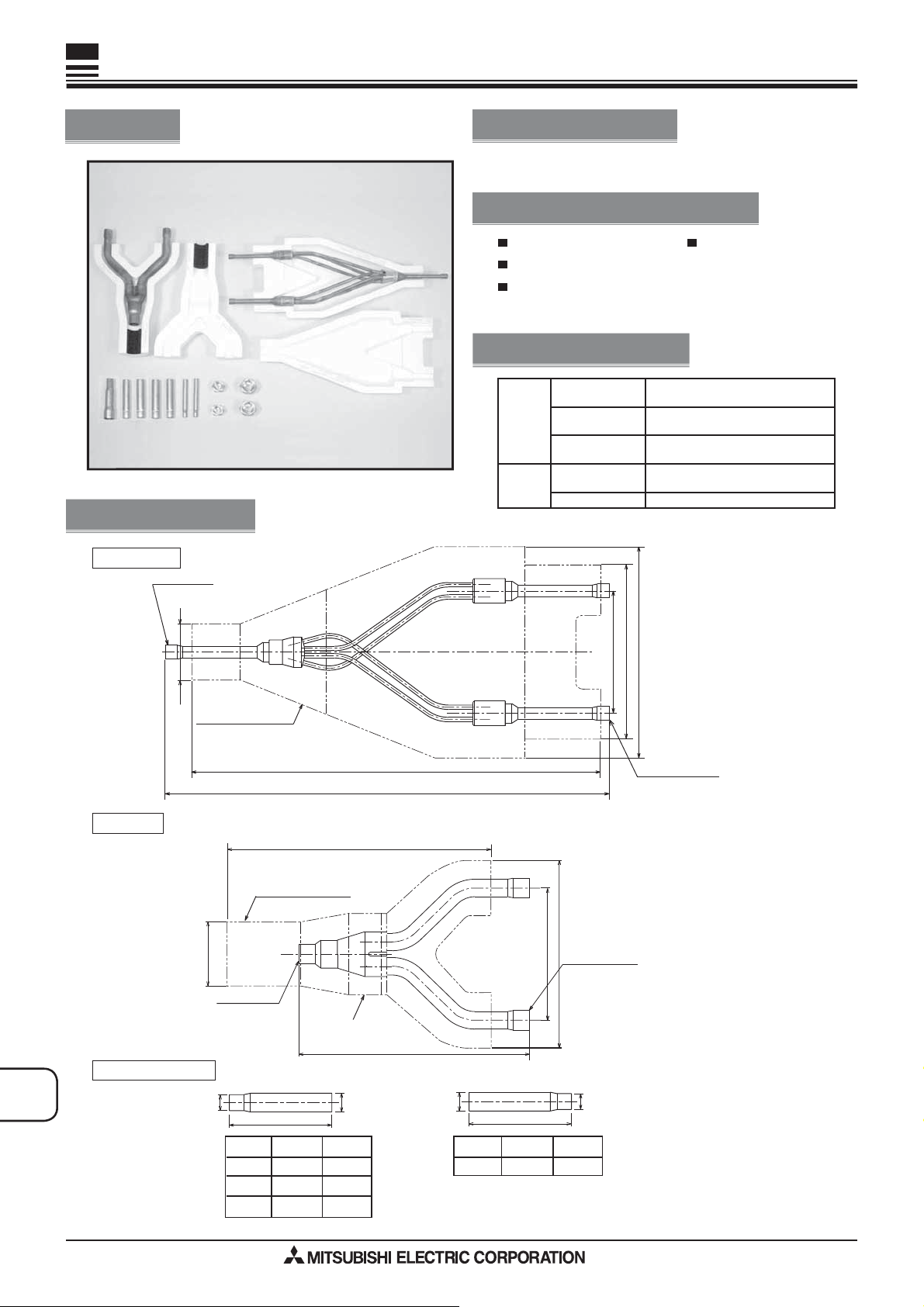
Photo
Dimensions
㪣㪠㪨㪬㪠㪛㩷㪧㪠㪧㪜
㱢㪐㪅㪌㪉㩿㪠㪛㪀
Unit : mm
Descriptions
Branch pipe for Multi-System Twin type Twin use. (50:50)
Applicable Models
PU-P71/100/125/140
PUH-P71/100/125/140
PUHZ-RP71/100/125/140
for Twin 50:50 use
PUHZ-HRP71/100/125
Specifications
Main body
Accessory
Distribution ratio
Number of
distribution pipes
Pipe material
Pipe cover
Joint
Outdoor unit capacity is divided into
two (50:50)
1 each for liquid pipe and gas pipe
Phosphate deoxidized copper
C1220T-OL (JIS H3300)
Styrofoam molding (1 each for liquid
pipe and gas pipe)
7 joints (4 types)
OPTIONAL
PAR TS
㪦㪬㪫㪛㪦㪦㪩
㪬㪥㪠㪫
㪪㪠㪛㪜
㱢㪋㪍
㪞㪘㪪㩷㪧㪠㪧㪜
㪦㪬㪫㪛㪦㪦㪩
㪬㪥㪠㪫
㪪㪠㪛㪜
㪡㪦㪠㪥㪫㩿㪘㪺㪺㪼㫊㫊㫆㫉㫐㪀
㪧㪠㪧㪜㩷㪚㪦㪭㪜㪩
䋨㪈㪎㪉㬍㪊㪊㪌㬍㪎㪉䋩
㪧㪠㪧㪜㩷㪚㪦㪭㪜㪩
䋨㪈㪎㪇㬍㪉㪋㪇㬍㪎㪋䋩
㱢㪌㪏
㱢㪈㪌㪅㪏㪏䋨㪠㪛䋩
㪊㪊㪌
㪋㪊㪌
㪉㪋㪇
㪧㪠㪧㪜㩷㪚㪦㪭㪜㪩
㪉㪈㪇
㪈㪉㪇
㪈㪎㪇
㪉㪄㱢㪈㪌㪅㪏㪏䋨㪠㪛䋩
㪈㪇㪇
㪈㪋㪉
㪈㪎㪉
㪠㪥㪛㪦㪦㪩
㪬㪥㪠㪫
㪪㪠㪛㪜
㪉㪄㱢㪐㪅㪌㪉䋨㪠㪛
㪠㪥㪛㪦㪦㪩
㪬㪥㪠㪫
㪪㪠㪛㪜
E-148
㱢䌁
㪏㪇
ΦA(ID)
ΦB(OD)
6.35
9.52 15.88 2
12.7 15.88 2
9.52
㱢䌂
Amount
2
㱢䌃
ΦC(ID)
19.05
㪏㪇
ΦD(OD)
15.88
㱢䌄
Amount
1
Page 2
Distribution Pipe MSDD-50TR-E
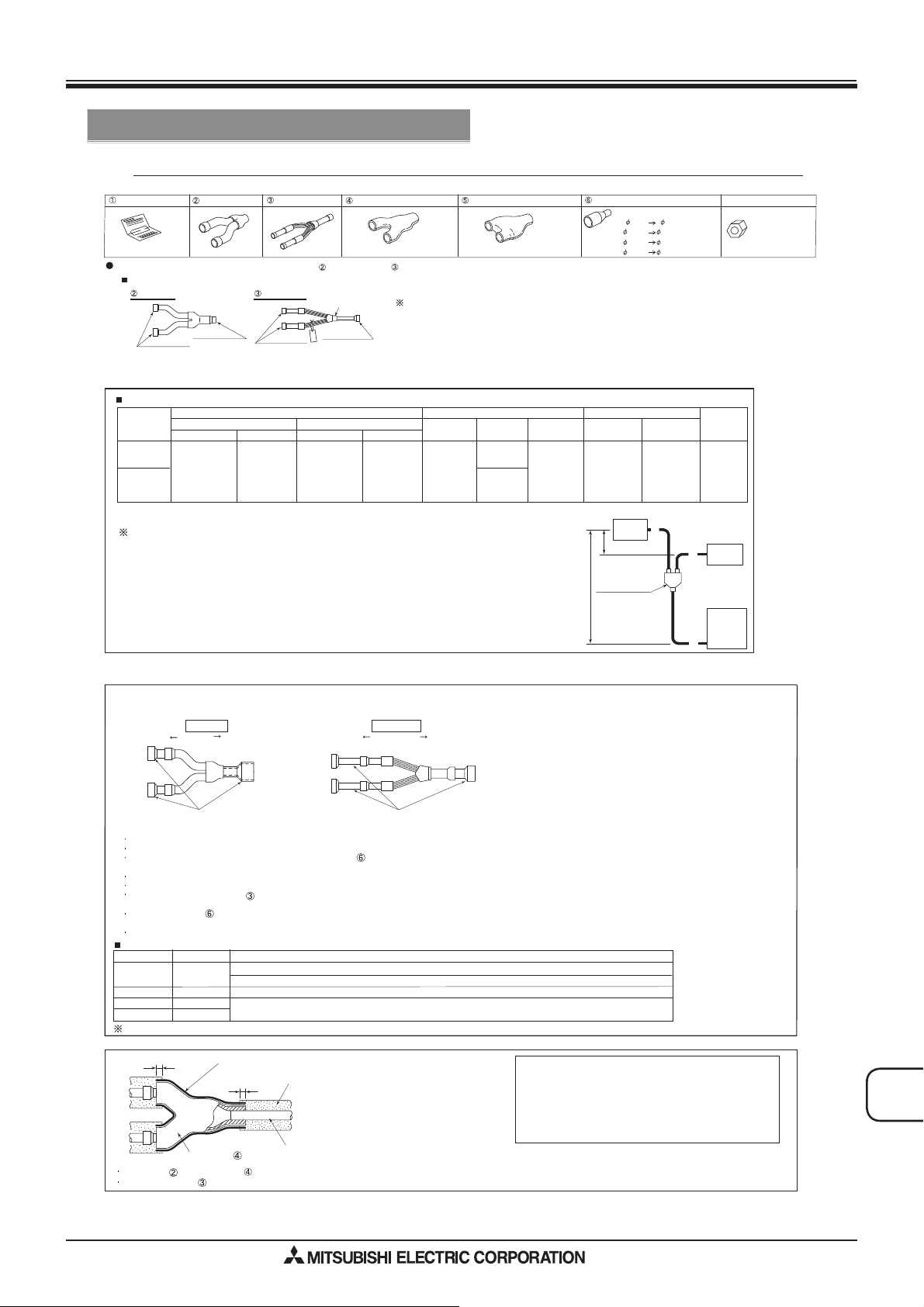
How to Use / How to Install
Package Air-conditioner Optional Parts Instruction Sheet for Simultaneous Twin Distributing Pipe
Make sure that you have all the following parts before installation.
Instruction sheet
This sheet 1 sheet
See the following for the specifications of gas pipe,and liquid pipe
MSDD-50TR
Gas pipe
ID Ǟ15.88
㧔to indoor unit㧕
Pipe size and limit to refrigerant pipe
For R410A (Table 1-2)
Outdoor
unit capacity
71(3Hp)
100
㨪
140
(4
㨪
6Hp)
Note 1: Limit the number of bends for refrigerant pipes to 8 in each of the ޛA㧗Bޜ and ޛA㧗Cޜ ranges.
See the installation manual provided with the main unit for details on chargeless pipe length and refrig erant additional charge amount.
Gas pipe
ID Ǟ15.88
㧔to outdoor unit㧕
Gas pipe side
Outdoor unit side Indoor unit side Outdoor unit side
Ǟ15.88
(5/8)
Liquid pipe
1pc
Liguid pipe
ID Ǟ9.52
㧔to indoor unit㧕
Pipe size (mm) Actual pipe length (m)
RP35, 50
Ǟ9.52(3/8)
Ǟ12.7(1/2)
RP60 125
~
Ǟ15.88(5/8)
Pipe cover (for gas pipe)
1pc
㧔Model name indication㧕
Tag
ID Ǟ9.52
㧔to outdoor unit㧕
Liquid pipe side
Ǟ9.52
3/8
Pipe cover (for liquid pipe) Joint pipe
1pc 1pc
,
Procure the following at local site in addition to the above
Tape for heat insulator sealing
Extended pipe for refrigerant pipe
Indoor unit side
RP35, 50
Ǟ6.35(1/4)
RP60
㨪
125
Ǟ9.52(3/8)
Indoor-Outdoor
A㧗B㧗C㧩
50m or less
㧙
75m or less
Indoor-Indoor
֥B㧙C֥㧩
8m or less
Height Difference (m)
Indoor-Outdoor
H =
30m or less
Indoor unit
(Fig. 1)ޓ
h
9.52 6.35···· 2pcs
15.88 12.7······ 2pcs
15.88 19.05···· 1pc
15.88 9.52······ 2pcs
Indoor-Indoor
h =
1m or less
B
C
Flare nut
For R410A indoor unit.
Note 1
Number
of bends
15 or less
Indoor unit
....
1/4F 2pcs
....
1/2F 2pcs
H
Distributing pipe
Pipe connections
Combination pattern of indoor and outdoor units and
joints to be used:
(Fig. 2)
Indoor side Outdoor side Indoor side Outdoor side
1. Perform work, taking care with the followings:
Be sure to check the combination pattern of indoor and outdoor units and joints to be used (Table 2).
Be sure to observe the limits to refrigerant pipe length and number of bends (Table 1).
Insert the refrigerant pipe (procured at local site) and joint into the expanded pipe portions of distributing pipe
(this product) until they stop, and then connect them using anti-oxidization soldering.
There is no restriction on the orientation of distributing pipe (this product)during installation.
Take care that no foreign object, such as dust, enters during pipe connecting work.
Remove the tag of liquid pipe after checking it.
2. Pipe connections
The provided joints will be necessary depending on the capability of model used: See (Table 2), and connect
ޓthe joints as shown in (Fig. 2).
Do not bend or widen the distributing pipe (liquid pipe).
For R410A
Outdoor unit
71(3Hp)
100(4Hp) 50+50 (2+2)
125(5Hp)
140(6Hp) 71+71 (3+3)
Installation positions in brackets ( ).
Gas pipe
Joints Joints
Indoor unit Joint to be used
35+35 (1.6+1.6)
60+60 (2.5+2.5)
Outer Ǟ15.88㧙inner Ǟ12.7 [indoor gas pipe side], Outer Ǟ9.52㧙inner Ǟ6.35 [indoor liquid pipe side]
Outer Ǟ15.88㧙inner Ǟ9.52 [indoor gas pipe side], Outer Ǟ9.52㧙inner Ǟ6.35 [indoor liquid pipe side]
Outer Ǟ15.88㧙inner Ǟ12.7 [indoor gas pipe side], Outer Ǟ9.52㧙inner Ǟ6.35 [indoor liquid pipe side]
No joint is necessary.
Liquid pipe
(Table 2-2)
Heat insulation work
Wrap margin (Note 2)
Fit gas pipe into pipe covers , and then seal the mated portion of pipe covers ԛ using heat insulation seal tape (procured at local site).
Process liquid pipe in the same way.
Tape (procured at local site)
(Note 1)
Wrap margin
Pipe cover
Please install contents other than this description on the main part of a product with an attached installation description, and use them as it.
Insulation material
(procured at local site) (Note 1)
Pipe from local site
Notes:
1.
Cover the entire refrigerant pipe (procured at local site)
with heat insulation material. When using generally available
heat insulation material, heat-resistant insulation material
(at least 12 mm thick).
2.
Pipe covers
Provide wrap margins with insulation material.
and will shrink slightly at high temperatures:
Outdoor unit
A
OPTIONAL
PAR TS
E-149
 Loading...