

Page 1
SPLIT-TYPE AIR CONDITIONERS
INDOOR UNIT
SERVICE MANUAL
Models
No. OBH536
MS-C08VC MS-C10VC MS-C13VC -
F1
F1
F1
Outdoor unit service manual
MU-C·VC Series (OBH537)
CONTENTS
1. TECHNICAL CHANGES ··································· 2
2. PART NAMES AND FUNCTIONS ····················· 2
3. SPECIFICATION ················································ 3
4. OUTLINES AND DIMENSIONS ························ 3
5. WIRING DIAGRAM ············································ 4
6. REFRIGERANT SYSTEM DIAGRAM ··············· 4
7. SERVICE FUNCTIONS ····································· 5
8. MICROPROCESSOR CONTROL ····················· 7
9. TROUBLESHOOTING ····································· 12
10. DISASSEMBLY INSTRUCTIONS ···················· 21
PARTS CATALOG (OBB536)
NOTE:
RoHS compliant products have <G> mark on the spec name plate.
TM
Page 2
1
TECHNICAL CHANGES
MS-C08VC MS-C10VC MS-C13VC -
1. New model
F1
F1
F1
2
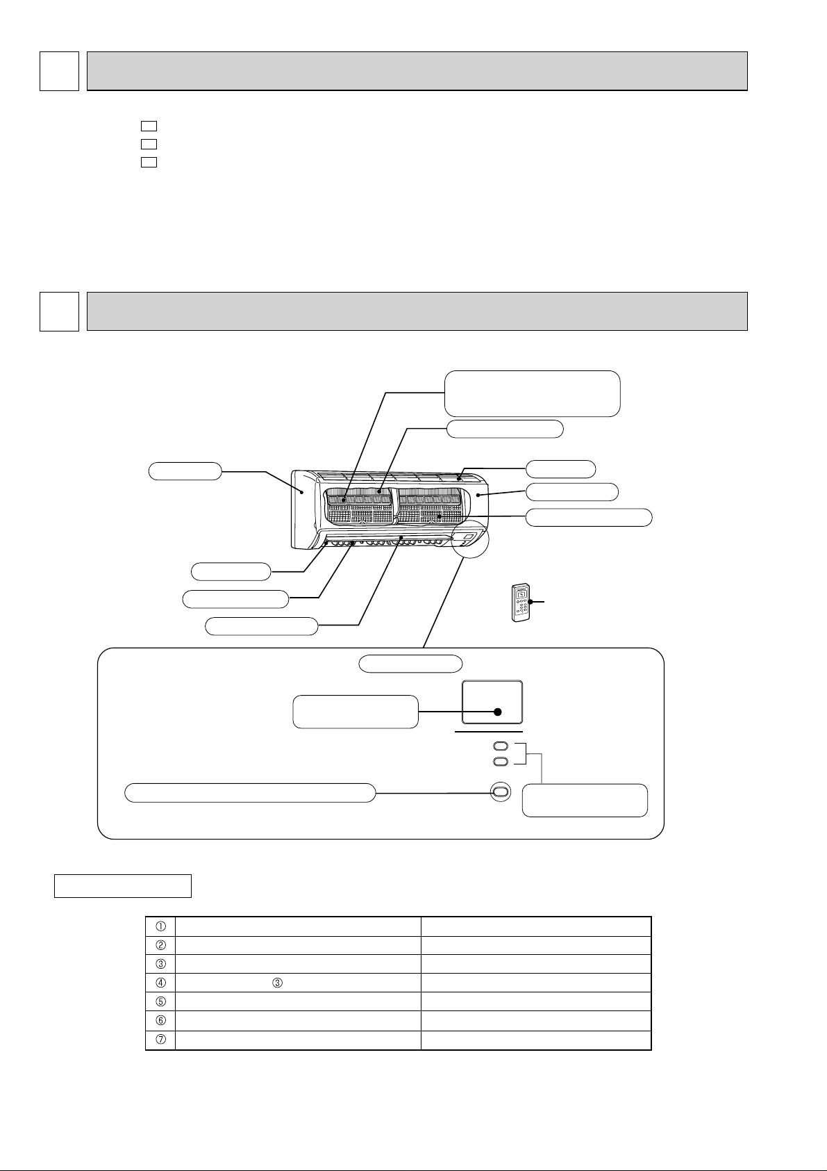
PART NAMES AND FUNCTIONS
MS-C08VC
MS-C10VC
MS-C13VC
Panel
Air outlet
Vertical vane
Air cleaning filter (Option)
(Anti-Allergy Enzyme Filter,
Blue bellows type)
Heat exchanger
Air inlet
Front panel
Catechin air filter
Remote controller
Horizontal vane
Display section
Remote control
receiving section
Emergency operation switch (E.O. SW)
ACCESSORIES
Installation plate
Installation plate fixing screw 4 x 25 mm
Remote controller holder
Fixing screw for 3.5 x 1.6 mm (Black)
Battery (AAA) for remote controller
Wireless remote controller
Felt tape (Used for left or left-rear piping)
2
Operation Indicator
lamp
1
5
1
2
2
1
1
Page 3
3
SPECIFICATION
Indoor model
Function
Power supply
Breaker capacity
Running current
Power input
Electrical
data
Model
Fan motor current
Fan
motor
Dimensions W
Weight
H D
A
A
W
A
mm
kg
MS-C08VC MS-C10VC MS-C13VC
Cooling
Single phase
220-230-240 V, 50 Hz
0.22
RC4V18-BA
0.22
788
295 225
Air direction
3
/h
Air flow (High/Med./Low)
Sound level (High/Med./Low)
Fan speed (High/Med./Low)
Special
remarks
m
dB
rpm
558/420/288
39/32/26
1,000/800/600
618/456/288
40/33/26
1,090/850/600
Fan speed regulator
Remote controller model
MP07A
NOTE : Test conditions are based on ISO 5151.
Cooling : Indoor Dry-bulb temperature 27 °C Wet-bulb temperature 19 °C
Outdoor Dry-bulb temperature 35 °C Wet-bulb temperature 24 °C
Indoor outdoor piping length : 5 m
10
45
9
4
624/480/330
42/36/29
1,100/880/660
3
4
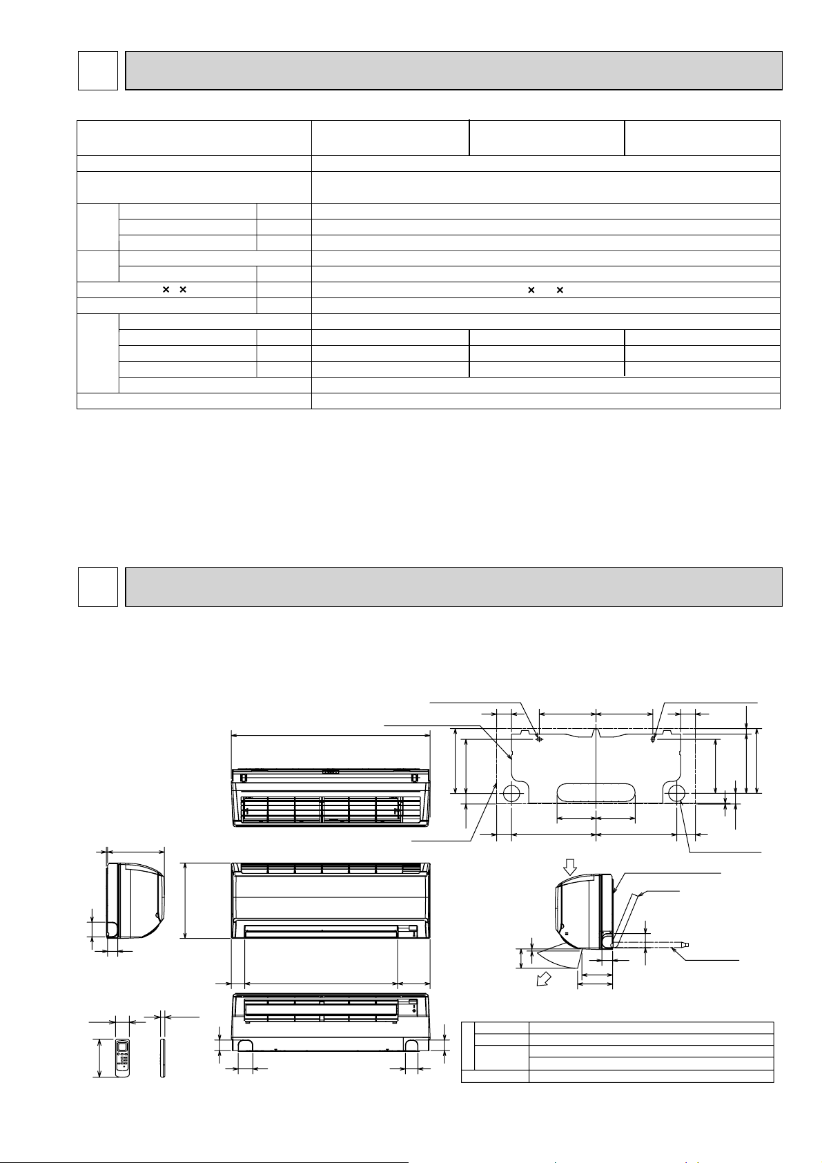
OUTLINES AND DIMENSIONS
MS-C08VC
MS-C10VC
MS-C13VC
2255
58
42
57
140
17.5
295
42
58
788
60753 128
Installation plate
Indoor unit
50
11X26 Oblong hole
254.5
21540.5
Insulation
42
Liquid line
Gas line
Piping
Drain hose
Unit : mm
11X20 Oblong hole
5959 225 225
214
155 155
320335
Air in
Installation plate
Piping
8
42
100
Air out
Φ35 O.D
Φ6.35 - 0.5m (Flared connection Φ6.35)
MS-C08/C10VCΦ9.52 - 0.43m (Flared connection Φ9.52)
MS-C13VCΦ12.7- 0.43m (Flared connection Φ12.7)
InsulationΦ28 Connected part Φ16 O.D
119
137
57
2
7459
Wall hole
Drain hose
41.5
Φ65
18.5
235
253.5
3
Page 4
5
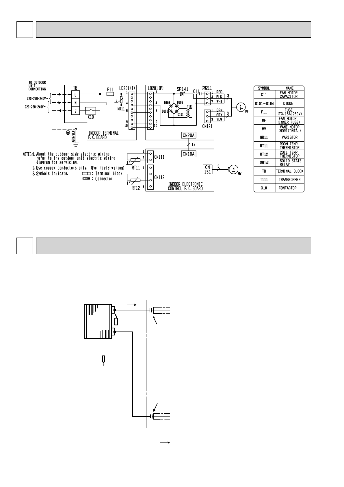
WIRING DIAGRAM
MS-C08VC
MS-C10VC
MS-C13VC
6
REFRIGERANT SYSTEM DIAGRAM
MS-C08VC
MS-C10VC
MS-C13VC
Indoor
heat
exchanger
Room temperature
thermistor
RT11
Indoor coil
thermistor
RT12
Unit : mm
Refrigerant pipe Φ9.52 (MS-C08/C10VC)
Φ12.7 (MS-C13VC)
(with heat insulator)
Flared connection
Flared connection
Refrigerant pipe Φ6.35
(with heat insulator)
Refrigerant flow in cooling
4
Page 5
7
SERVICE FUNCTIONS
MS-C08VC
MS-C10VC
MS-C13VC
7-1. TIMER SHORT MODE
For service, set time can be shortened by short circuit of JPG and JPS on the electronic control P.C. board.
The time will be shortened as follows: (Refer to 9-7.)
Set time : 1-minute → 1-second
Set time : 3-minute
shortened by short circuit-of JPG and JPS.)
7-2. P.C. BOARD MODIFICATION FOR INDIVIDUAL OPERATION
A maximum of 4 indoor units with wireless remote controllers can be used in a room.
In this case, to operate each indoor unit individually by each remote controller, P.C. boards of remote controller must be
modified according to the number of the indoor unit.
How to modify the remote controller P.C. board
Remove batteries before modification.
The board has a print as shown below :
→ 3-second (It takes 3 minutes for the compressor to start operation. However, the starting time is
J2
J1
NOTE : For modification, take out
the batteries and press
the OPERATE/STOP(ON/
OFF)button twice or 3
times at first.
After modification, put back
the batteries then press the
RESET button.
The P.C. board has the print “J1” and “J2”. Solder “J1” and “J2” according to the number of indoor unit as shown in Table 1.
After modification, press the RESET button.
Table 1
4 units operation
Same as at left
Same as at left
Same as at left
Solder both J1 and J2
No. 1 unit
No. 2 unit
No. 3 unit
No. 4 unit
1 unit operation
No modification
–
–
–
2 units operation
Same as at left
Solder J1
–
–
3 units operation
Same as at left
Same as at left
Solder J2
–
How to set the remote controller exclusively for particular indoor unit
After you turn the breaker on, the first remote controller that sends the signal to the indoor unit will be regarded as the remote
controller for the indoor unit.
The indoor unit will only accept the signal from the remote controller that has been assigned to the indoor unit once they are
set.
The setting will be cancelled if the breaker has turned off, or the power supply has shut down.
Please conduct the above setting once again after the power has restored.
5
Page 6
7-3. AUTO RESTART FUNCTION
When the indoor unit is controlled with the remote controller, the operation mode, the set temperature, and the fan speed
are memorized by the indoor electronic control P.C. board. The “AUTO RESTART FUNCTION” sets to work the moment
power has restored after power failure. Then, the unit will restart automatically.
Operation
1
When the main power is cut off, the operation settings remain.
2
After the power is restored, the unit restarts automatically according to the memory.
(However, it takes at least 3 minutes
for the compressor to start running.)
How to release “AUTO RESTART FUNCTION”
1
Turn off the main power for the unit.
2
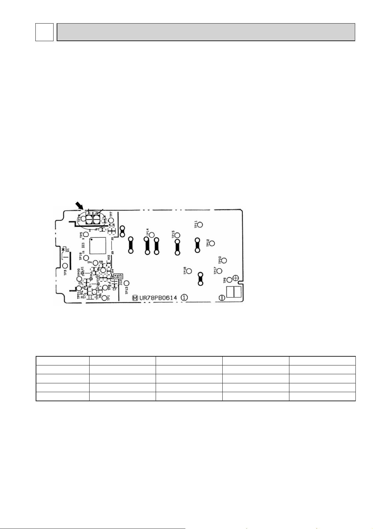
Solder the Jumper wire to JR07 on the indoor electronic control P.C. board. (Refer to 9-7.)
MS-C08/C10/C13VC
Indoor electronic
control P.C. board
CN10A CN111CN151 CN112
JR07
NOTE:
• The operation settings are memorized when 10 seconds have passed after the indoor unit was operated with the
remote controller.
• If main power is turned off or a power failure occurs while AUTO START/STOP timer is active, the timer setting is
cancelled.
• If the unit has been off with the remote controller before power failure, the auto restart function does not work as the
power button of the remote controller is off.
• To prevent breaker off due to the rush of starting current, systematize other home appliance not to turn on at the
same time.
• When some air conditioners are connected to the same supply system, if they are operated before power failure, the
starting current of all the compressors may flow simultaneously at restart.
Therefore, the special counter-measures are required to prevent the main voltage-drop or the rush of the starting
current by adding to the system that allows the units to start one by one.
6
Page 7
8
MICROPROCESSOR CONTROL
MS-C08VC MS-C10VC MS-C13VC
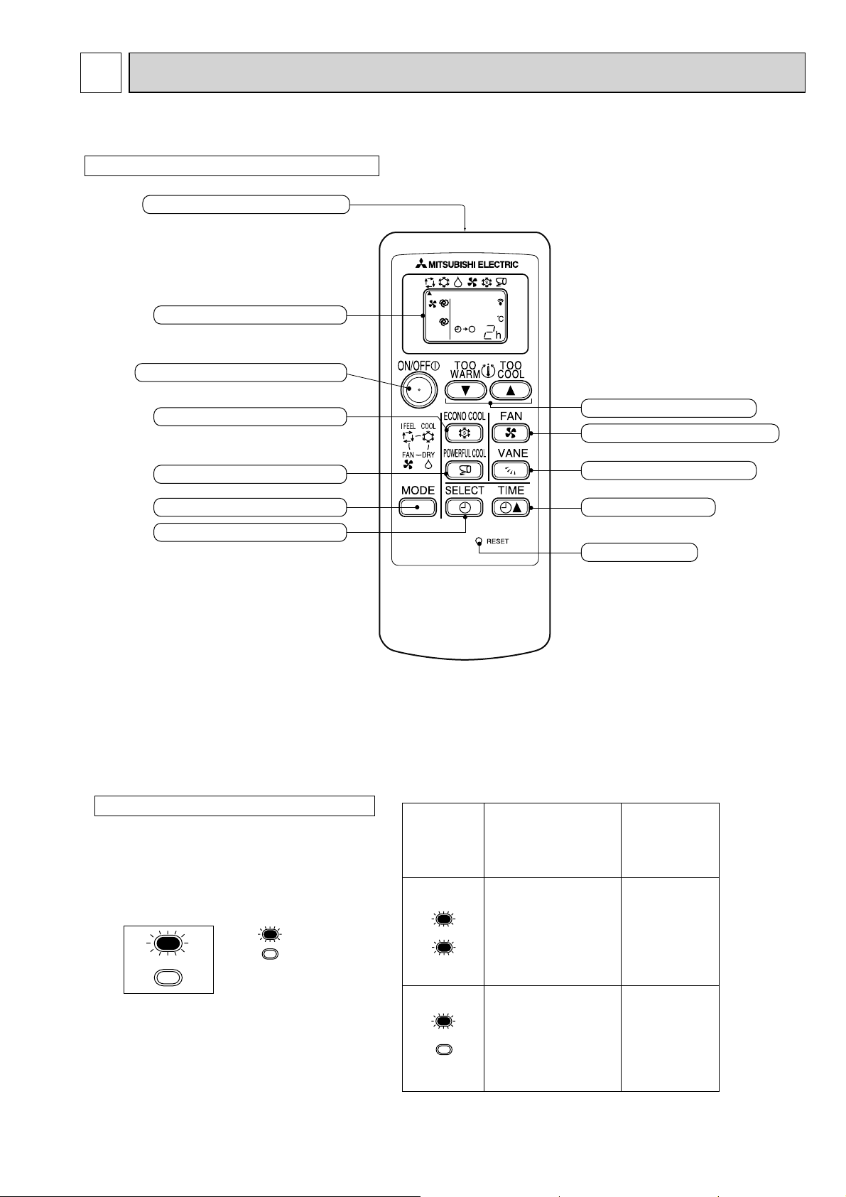
WIRELESS REMOTE CONTROLLER
Signal transmitting section
Operation display section
OPERATE/STOP (ON/OFF) button
ECONO COOL button
POWERFUL COOL button
OPERATION SELECT button
TIMER MODE SELECT button
NOTE: • Last setting will be stored after the unit is turned OFF with the remote controller.
• Indoor unit receives the signal of the remote controller with beeps.
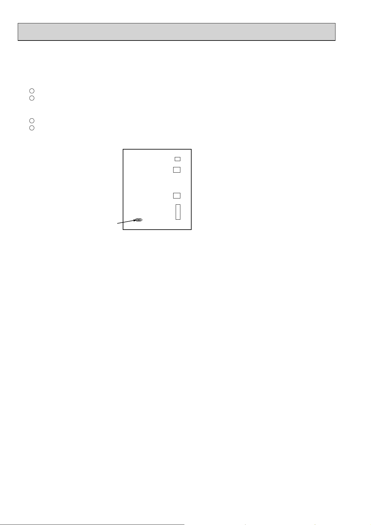
INDOOR UNIT DISPLAY SECTION
Operation Indicator lamp
The operation indicator at the right side of the indoor
unit indicates the operation state.
Operation Indicator
Lighted
Not lighted
Indication
Operation state
This shows that the
air conditioner is
operating to reach
the target temperature.
Please wait until the
target temperature is
obtained.
TEMPERATURE buttons
FAN SPEED CONTROL button
VANE CONTROL button
TIME SET button
RESET button
Difference
between target
temperature
and room
temperature
Approx. 2°C
or more
This shows that the
room temperature is
approaching the
target temperature.
7
Approx. 2°C
or less
Page 8
8-1. COOL ( ) OPERATION
(1) Press OPERATE/STOP(ON/OFF) button.
OPERATION INDICATOR lamp of the indoor unit turns on with a beep tone.
(2) Select COOL mode with OPERATION SELECT button.
(3) Set TEMPERATURE buttons.
Press TOO WARM or TOO COOL button to select the desired temperature.
The setting range is 16 ~ 31°C.
1. Coil frost prevention
When the temperature of indoor heat exchanger becomes too low, the coil frost prevention mode works.
The indoor fan operates at the set speed and the compressor stops.
This mode continues until the temperature of indoor heat exchanger rises.
8-2. DRY (
)OPERATION
(1) Press OPERATE/STOP(ON/OFF) button.
OPERATION INDICATOR lamp of the indoor unit turns on with a beep tone.
(2) Select DRY mode with OPERATION SELECT button.
(3) The set temperature is determined from the initial temperature.
1. Coil frost prevention
• The operation is the same as coil frost prevention during COOL mode.
8-3. FAN (
)OPERATION
(1) Press OPERATE/STOP(ON/OFF) button. OPERATION INDICATOR lamp of the indoor unit turns on with a beep tone.
(2) Select FAN mode with OPERATION SELECT button.
(3) Select the desired fan speed. When AUTO, it becomes Low.
Only indoor fan operates.
Outdoor unit does not operate.
8-4. “I FEEL CONTROL” (
(1) Press OPERATE/STOP(ON/OFF) button on the remote controller.
) OPERATION
Initial room temperature
Mode
OPERATION INDICATOR lamp of the indoor unit turns on with a beep
tone.
(2) Select “I FEEL CONTROL”(
) mode with the
OPERATION SELECT button.
(3) The operation mode is determined by the initial room
25°C or more
more than 13°C,
less than 25°C
COOL mode of
“I FEEL CONTROL”
DRY mode of
“I FEEL CONTROL”
temperature at start-up of the operation.
• Once the mode is fixed, the mode is not changed by room temperature afterwards.
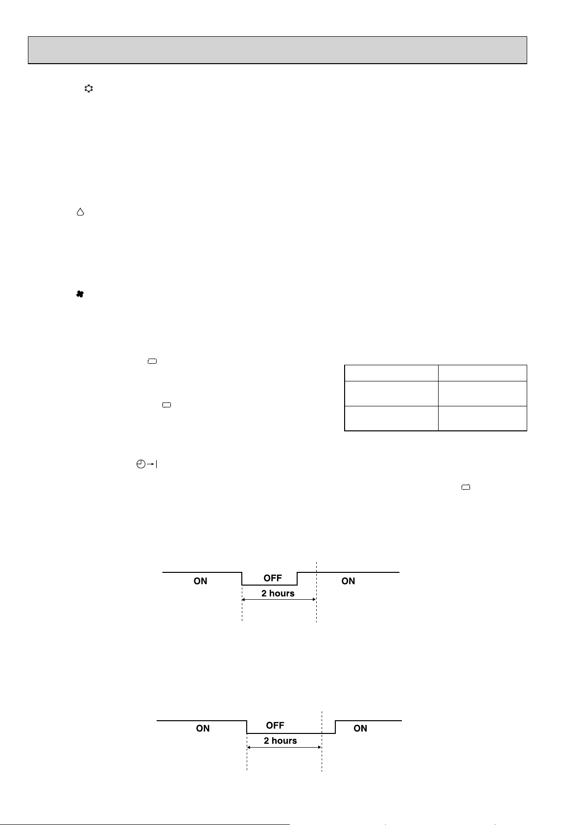
• Under ON-TIMER (
When the system is stopped by the remote controller and restarted within 2 hours in “I FEEL CONTROL”
) operation, the mode is determined as follows:
( ) mode, the
system operates in previous mode automatically regardless of the room temperature.
Operation time chart
Example
Previous operation
COOL mode of
“I FEEL CONTROL”
or COOL mode
Restart
COOL mode of
“I FEEL CONTROL”
When the system is restarted after 2 hours and more, the operation mode is determined by the room temperature at
start-up of the operation.
Operation time chart
Example
Previous operation
COOL mode of
“I FEEL CONTROL”
or COOL mode
Restart
COOL or DRY mode of
“
I FEEL CONTROL”
determined
temperature at start-up
of the operation.
that
by room
8
Page 9

(4) The initial set temperature is decided by the initial room temperature.
Mode
Initial room temperature
Initial set temperature
26°C or more 24°C
COOL mode of
“I FEEL CONTROL”
Initial room temperature
minus 2
°C
Initial room temperature
minus 2
°C
DRY mode of
“I FEEL CONTROL”
25°C to 26°C
more than13°C, less than 25°C
1 When the system is restarted with the remote controller, the system operates with the previous set temperature
regardless of the room temperature at restart.
The set temperature is calculated by the previous set temperature.
(5) TEMPERATURE buttons
In “I FEEL CONTROL” mode, set temperature is decided by the microprocessor based on the room temperature.
In addition, set temperature can be controlled by TOO WARM or TOO COOL buttons when you feel too cool or too warm.
Each time the TOO WARM or TOO COOL button is pressed, the indoor unit receives the signal and emits a beep tone.
• Fuzzy control
When the TOO COOL or TOO WARM button is pressed, the microprocessor changes the set temperature, considering
the room temperature, the frequency of pressing TOO COOL or TOO WARM button and the user’s preference to heat or
cold. So this is called “Fuzzy control”, and works only in “I FEEL CONTROL” mode.
In DRY mode of “I FEEL CONTROL”, the set temperature doesn’t change.
TOO
COOL
…
To raise the set temperature 1 ~ 2 degrees (°C)
1
TOO
WARM
…
To lower the set temperature 1 ~ 2 degrees (°C)
8-5. AUTO VANE OPERATION
1. Horizontal vane
(1) Vane motor drive
These models are equipped with a stepping motor for the horizontal vane. The rotating direction, speed, and angle of
the motor are controlled by pulse signals, which are approximately 12V and transmitted from microprocessor.
(2) The horizontal vane angle and mode change as follows by pressing VANE CONTROL button.
AUTO SWING
(3) Positioning
The vane is once pressed to the vane stopper below to confirm the standard position and then set to the desired angle.
Confirming of standard position is performed in case of follows.
(a) When the operation starts or finishes (including timer operation).
(b) When the test run starts.
1234
9
Page 10

(4) VANE AUTO (
) mode
In VANE AUTO mode, the microprocessor automatically determines the vane angle to make the optimum room-temperature distribution.
Vane angle is fixed to Horizontal position.
Horizontal position
(5) STOP (operation OFF) and ON-TIMER standby
When the following cases occur, the horizontal vane returns to the closed position.
(a) When OPERATE/STOP(ON/OFF) button is pressed (POWER OFF).
(b) When the operation is stopped by the emergency operation.
(c) When the ON-TIMER is on standby.
(6) Dew prevention
During COOL or DRY operation at Vane Angle 2 ~ 4 when the cumulative operation time of compressor exceeds 1 hour,
the vane angle automatically changes to Angle 1 for dew prevention.
(7) SWING MODE (
)
By selecting SWING mode with VANE CONTROL button the horizontal vane swings vertically. The remote controller
displays “
”. SWING mode is cancelled when VANE CONTROL button is pressed once again.
(8) ECONO COOL (
) operation
When the ECONO COOL button is pressed in COOL mode, set temperature is automatically set 2°C higher.
Also the horizontal vane swings in a cycle.
SWING operation makes you feel cooler than set temperature. So, even though the set temperature is higher, the air
conditioner can keep comfort. As a result, energy can be saved.
ECONO COOL operation is cancelled when ECONO COOL button, VANE CONTROL button or POWERFUL COOL but-
ton is pressed or change to other operation mode.
NOTE : ECONO COOL operation does not work in COOL mode of “I FEEL CONTROL”.
(9) POWERFUL COOL (
) mode
When POWERFUL COOL button is pressed in COOL mode, the fan speed and the set temperature are automatically
adjusted.
Operation becomes POWERFUL COOL mode.
POWERFUL COOL mode is automatically released 15 minutes after operation starts, and the operation mode returns to
the mode prior to POWERFUL COOL operation.
POWERFUL COOL mode is also cancelled when POWERFUL COOL button is pressed once again, OPERATE/STOP
(ON/OFF) button is pressed, FAN SPEED CONTROL button is pressed, ECONO COOL button is pressed in COOL
mode, ON-TIMER is set or change to other operation mode.
NOTE: 1. TEMPERATURE buttons are not available during POWERFUL COOL operation.
2. VANE CONTROL button is available.
(10) To change the airflow direction not to blow directly onto your body.
To change the air
flow direction
Pressing and holding
VANE CONTROL
button for 2 seconds
or more causes
the horizontal vane
to reverse and
move to horizontal
position.
Horizontal
position
When to use this function?
Use this function if you don’t
want the air from the indoor
unit to blow directly onto your
body.
• Depending on the shape of
the room, the air may blow
directly onto your body.
• Press VANE CONTROL
button again to return the
vane to the previously-set
position.
COOL/DRY/FAN
The air conditioner starts the
cooling or drying operation
approx. 3 minutes after the
vane has moved to the horizontal position.
• When VANE CONTROL
button is pressed again,
the vane returns to the
previously-set position
and the air conditioner
starts the cooling or
drying operation in
approx. 3 minutes.
NOTE: 1. If you make the airflow not to blow directly onto your body by pressing VANE CONTROL button,
the compressor stops for 3 minutes even during the operation of the air conditioner.
2. The air conditioner operates with decreased airflow until the compressor turns on again.
10
Page 11

8-6. TIMER OPERATION
1. How to set the timer
(1) Press OPERATE/STOP (ON/OFF) button to start the air conditioner.
(2) Press TIMER MODE SELECT button
“
Each time this button is pressed, the timer mode is changed in sequence.
(3) Press TIME SET button (
”(OFF TIMER) → “
TIME
) to set the timer.
SELECT
(
) to select the operation.
”(ON TIMER) → TIMER RELEASE
Each time this button is pressed, the set time increases by 1 hour to 12 hours.
NOTE: 1. Be sure to place the remote controller at the position where its signal can reach the air conditioner even during
TIMER operation.
2. Reset the timer in the following cases, or the set time may deviate and other malfunctions may occur.
• A power failure occurs.
• The circuit breaker functions.
3. The OFF TIMER and ON TIMER can not be set at the same time.
(Example 1) Setting to stop the air conditioner 3 hours later.
(Example 2) Setting to operate the air conditioner 7 hours later.
Press “
2. Cancel
Press “
Press “ ” button to select “ ”
(OFF TIMER).
Press “ ” button to set the “3h”.
” button to select “ ” (ON TIMER).
Press “ ” button to set the “7h”.
” button until “” (OFF TIMER) and “” (ON TIMER) are not displayed.
h
h
8-7. EMERGENCY/TEST OPERATION
In case of test run operation or emergency operation, use EMERGENCY OPERATION switch on the front of the indoor
unit. Emergency operation is available when the remote controller is missing, has failed or the batteries of remote controller run down. The unit will start and OPERATION INDICATOR lamp will light.
The first 30 minutes of operation is the test run operation. This operation is for servicing. Indoor fan runs at High speed
and the unit continues to operate with the thermostat on.
After 30 minutes of test run operation, the system shifts to EMERGENCY COOL MODE with a set temperature of 24°C.
The fan speed shifts to Med.
The coil frost prevention works even in emergency operation.
In the test run or emergency operation, the horizontal vane operates in VANE AUTO (
Emergency operation continues until EMERGENCY OPERATION switch is pressed again or the unit receives any signal
from the remote controller. In case of latter, normal operation will start.
NOTE : Do not press EMERGENCY OPERATION switch during normal operation.
OPERATION INDICATOR lamp
Press once <Cool>
EMERGENCY OPERATION switch
Press again <Stop>
) mode.
Lighted
Not lighted
8-8. 3-MINUTE TIME DELAY OPERATION
When the system turns OFF, compressor will not restart for 3 minutes as 3-minute time delay function operates to protect
compressor from overload.
11
Page 12

9
TROUBLESHOOTING
MS-C08VC
MS-C10VC
MS-C13VC
9-1. CAUTIONS ON TROUBLESHOOTING
1. Before troubleshooting, check the following:
1) Check the power supply voltage.
2) Check the indoor/outdoor connecting wire for mis-wiring.
2. Take care of the following during servicing
1) Before servicing the air conditioner, be sure to turn off the unit first with the remote controller, and then after
confirming the horizontal vane is closed, turn off the breaker and / or disconnect the power plug.
2) Be sure to turn off the power supply before removing the front panel, the cabinet, the top panel, and the P.C. board.
3) When removing the P.C. board, hold the edge of the board with care NOT to apply stress on the components.
4) When connecting or disconnecting the connectors, hold the housing of the connector. DO NOT pull the lead wires.
Lead wiring
3. Troubleshooting procedure
1) First, check if the OPERATION INDICATOR lamp on the indoor unit is flashing on and off to indicate an abnormality.
To make sure, check how many times the abnormality indication is flashing on and off before starting service work.
2) Before servicing, check that the connector and terminal are connected properly.
3) When the P.C. board seems to be defective, check the copper foil pattern for disconnection and the components for
bursting and discoloration.
4) Refer to 9-2, 9-3 and 9-4.
4. How to replace batteries
Weak batteries may cause the remote controller malfunction.
In this case, replace the batteries to operate the remote controller normally.
1
Remove the back lid and insert batteries.
Then reattach the back lid.
Insert the negative pole of the
batteries first. Check if the polarity
of the batteries is correct.
NOTE : 1. If RESET button is not pressed, the remote controller may not operate correctly.
2. This remote controller has a circuit to automatically reset the microcomputer when batteries are replaced.
This function is equipped to prevent the microcomputer from malfunctioning due to the voltage drop caused by
the battery replacement.
Housing point
2
Press RESET button with instrument, and then use
the remote controller.
RESET button
12
Page 13

9-2. FAILURE MODE RECALL FUNCTION
Outline of the function
This air conditioner can memorize the abnormal condition which has occurred once.
Even though OPERATION INDICATOR lamp indication listed on the troubleshooting check table (9-4.) disappears, the
memorized failure details can be recalled.
This mode is very useful when the unit needs to be repaired for the abnormality which does not recur.
1. Flow chart of failure mode recall function for the indoor unit
Operational procedure
The cause of abnormality cannot be found because the abnormality does not recur.
Setting up the failure mode recall function
Turn on the power supply.
<
Preparation of the remote controller
1 While pressing both OPERATION SELECT
button and TOO COOL button on the remote controller at the same time, press
RESET button.
2 First, release RESET button.
And release the other two buttons after all LCD in
operation display section of the remote controller is displayed after 3 seconds.
Press OPERATE/STOP(ON/OFF) button of the remote controller (the set temperature
is displayed) with the remote controller headed towards the indoor unit. 1
Does the upper or left lamp of
OPERATION INDICATOR lamp on the indoor unit
blink at the interval of 0.5 seconds?
Blinks: Indoor unit is abnormal.
Beeps are emitted at the same timing
as the blinking of the upper or left lamp of
OPERATION INDICATOR lamp. 2
>
Yes
(Blinks)
No
(OFF)
1. Regardless of normal or abnormal, a short
beep is emitted once the signal is received.
Indoor unit is normal.
But the outdoor unit might be abnormal because there are some
abnormalities that cannot be recalled with this way.
The indoor unit is abnormal.
Check the blinking pattern, and confirm the abnormal point with the indoor unit
failure mode table(9-2.2.).
Make sure to check at least two consecutive blinking cycles. 2
Releasing the failure mode recall function
Release the failure mode recall function by the following procedures.
• Turn off the power supply and turn it on again.
• Press RESET button of the remote controller.
Repair the defective parts.
Deleting the memorized abnormal condition
1 After repairing the unit, recall the failure mode again according to
"Setting up the failure mode recall function" mentioned above.
2 Press OPERATE/STOP(ON/OFF) button of the remote controller (the set temperature is displayed)
with the remote controller headed towards the indoor unit.
3 Press EMERGENCY OPERATION switch so that the memorized abnormal condition is deleted.
4 Release the failure mode recall function according to "Releasing the failure mode recall function"
mentioned above.
Note: 1. Make sure to release the failure mode recall function once it is set up, otherwise the unit cannot operate properly.
2. If the abnormal condition is not deleted from the memory, the last abnormal condition is kept memorized.
2. Blinking pattern when the indoor unit is abnormal:
Blinking at 0.5-
second interval
Beeps
Beeps
Repeated cycle
ON
OFF
Blinking at 0.5-
2.5-second OFF
Repeated cycle Repeated cycle
second interval
Beeps
2.5-second OFF
13
Page 14

2. Indoor unit failure mode table
Left lamp of OPERATION
INDICATOR lamp
Not lighted –Normal –
1-time flash
every 0.5-second
2-time flash
2.5-second OFF
11-time flash
2.5-second OFF
12-time flash
2.5-second OFF
Abnormal point
(Failure mode)
Room temperature
thermistor
Indoor coil thermistor
Indoor fan motor
Indoor control system
Detection method
When the room temperature thermistor short
or open circuit is detected every 8
seconds during operation.
When the indoor coil thermistor short or open
circuit is detected every 8 seconds during
operation.
When the rotational frequency feedback
signal is not emitted during the 12-seconds
the indoor fan operation.
When it cannot properly read data in the
nonvolatile memory of the indoor electronic
control P.C. board.
Correspondence
Refer to the characteristics of the room
temperature thermistor (9-7.).
Refer to the characteristics of the
indoor coil thermistor (9-7.).
A
Refer to 9-6.
motor".
Replace the indoor electronic control
P.C. board.
"Check of indoor fan
NOTE : Blinking patterns of this mode differ from the ones of Troubleshooting check table (9-4.).
14
Page 15

9-3. INSTRUCTION OF TROUBLESHOOTING
Start
Indoor unit
operates.
Outdoor unit
does not
operate.
Outdoor unit
operates in
only Test Run
operation.
Check room
temperature
thermistor.
Refer to 9-7.
"Test point
diagram and
voltage".
Outdoor unit
does not
operate
even in
Test Run
operation.
Check of
wiring
diagram
of outdoor
unit.
Indoor and
outdoor unit
do not
operate.
Check
outdoor
fuse (F or F1)
and
compressor
contactor
(52C)
.
Indoor unit
does not receive
the signal from
remote controller.
Indoor unit
operates, when
the EMERGENCY
OPERATION
switch is pressed.
Refer to
"Check of
remote controller
and receiver
P.C. board".
Indoor unit
does not operate,
when the
EMERGENCY
OPERATION
switch is pressed.
1. Check indoor/outdoor
connecting wire.
(Check if the power
is supplied to the
indoor unit.)
2. Check outdoor
F or F1
fuse (
3. Refer to 9-6.
).
C
"Check of indoor
electronic control
P.C. board and indoor
fan motor".
OPERATION INDICATOR
lamp on the indoor unit is
flashing on and off.
Upper or left lamp
2-time flash
Cause:
Indoor unit
• Trouble of room
temperature/
indoor coil
thermistor
Check room
temperature
thermistor and
indoor coil thermistor.
Refer to 9-7.
"Test point diagram
and voltage".
Upper or
left lamp
3-time flash
Cause:
Indoor unit
• Trouble of
indoor fan
motor
Refer to
A
9-6.
"Check of
indoor fan
motor".
15
Upper or
left lamp
4-time flash
Cause:
Indoor unit
• Trouble of
indoor control
system
Replace the
indoor
electronic
control P.C.
board.
"Test Run operation" means the
operation within 30 minutes after
EMERGENCY OPERATION switch
is pressed.
Refer to outdoor unit service manual.
Page 16

9-4. TROUBLESHOOTING CHECK TABLE
Before taking measures, make sure that the symptom reappears for accurate troubleshooting.
When the indoor unit has started operation and the following detection method has detected an abnormality (the first
detection after the power is turned on), the indoor electronic control P.C. board turns off the indoor fan motor with
OPERATION INDICATOR lamp flashing.
OPERATION INDICATOR
Lighted
Blinking
Not lighted
Abnormal
No.
point
SymptomOperation indicator lamp
Condition
Correspondence
Indoor coil
thermistor
1
Room
temperature
thermistor
2
Indoor fan
motor
Indoor
control
3
system
Upper or left lamp flashes.
2-time flash
2.5-second OFF
Upper or left lamp flashes.
3-time flash
2.5-second OFF
Upper or left lamp flashes.
4-time flash
2.5-second OFF
9-5. TROUBLE CRITERION OF MAIN PARTS
MS-C08VC
MS-C10VC
MS-C13VC
Part name FigureCheck method and criterion
Room temperature
thermistor (RT11)
Indoor coil thermistor
(RT12)
Measure the resistance with a tester.
(Part temperature 10°C ~ 30°C)
Refer to 9-7."Test point diagram and voltage",
"Indoor electronic control P.C. board", for the chart of thermistor.
Measure the resistance with a tester.
(Part temperature 10°C ~ 30°C)
Indoor unit
and outdoor
unit do not
operate.
When the indoor coil or the room temperature
thermistor is short or open circuit.
When the rotational frequency feedback
signal is not emitted during the indoor fan
operation.
When it cannot properly read data in the
nonvolatile memory of the indoor electronic
• Refer to the characteristics of
the indoor coil thermistor, and
the room temperature
thermistor (9-7).
• Refer to 9-6.
indoor fan motor".
• Replace the indoor electronic
control P.C. board.
A
"Check of
Indoor fan motor (MF)
INNER FUSE
145 ± 2°C CUT OFF
Horizontal vane
motor (MV)
Color of the lead wire
Motor part
WHT-BLK
BLK-RED
Color of the lead wire
BRN-YL W
Normal
295 Ω ~ 320 Ω
273 Ω ~ 296 Ω
Normal
4.5 ~ 5.5V
(When fan revolved one time)
Sensor part
BRN-GRY
0V → 5V → 0V
(Approx.)
Measure the resistance between the terminals with a tester.
(Part temperature 10°C ~ 30°C)
Normal
240 Ω ~ 260 Ω
16
BLK
BLK
RED
BLK
FUSE
MAIN
AUX.
REDWHT
ROTOR
BLK
BLK
Page 17

9-6. TROUBLESHOOTING FLOW
When OPERATION INDICATOR lamp flashes 3 times.
Indoor fan does not operate.
A
Check of indoor fan motor
Turn off the power supply.
Check connector CN211 visually.
Reconnect the lead wires.
Disconnect lead wires from connector CN211 on indoor power P.C. board.
Measure the resistance between lead wires No.1 and No.4 and then No.4 and No.7.
Fuse (F11)
No
Is the resistance 0 (short circuit) or ∞ (open circuit)?
Indoor terminal
P.C.board
Are lead wires connected?
Yes ( 0 or ∞ )
Replace the indoor fan motor.
Indoor power P.C.board
Varistor
(NR11)
Yes
CN121
CN211
Are soldered points of the
connector correctly soldered to
the indoor power P.C. board?
Yes
Turn on the power supply. Stop it if the unit operates.
Insert screwdriver into air outlet to rotate indoor fan
motor slowly for 1 revolution or over, and measure the
No
(others)
voltage No.2(+) and No.1(-) on CN121.
No
Does the voltage repeat 0 V DC and 5 V DC?
Replace the indoor power/terminal P.C. board and
the indoor control P.C. board.
No
Yes
Resolder it.
17
Page 18

Indoor unit operates by pressing EMERGENCY OPERATION switch, but does not operate with the remote controller.
Check of remote controller and receiver P.C. board B
Check if the remote controller is exclusive for this air conditioner.
Press OPERATE/STOP (ON/OFF)
button on the remote controller.
Is LCD display on the remote
controller visible?
Yes
Remove the batteries, then set them back
and press RESET button.
Check if the unit operates with the remote
controller.
Does the unit operate with the
remote controller?
Yes
OK
No
(not clear)
No
Replace the batteries. (Refer to 9-1.4.)
Turn on a radio to AM and press
OPERATE/STOP (ON/OFF) button
on the remote controller.
Is noise heard from radio?
Yes
Are there any fluorescent lights of
inverter or rapid-start type within
the range of 1 m?
No
Replace the indoor electronic
control P.C. board.
No
Yes
Replace the remote controller.
• Reinstall the unit away from lights.
• Attach a filter on receiving part.
18
Page 19

The unit does not operate with the remote controller.
Also, OPERATION INDICATOR lamp does not light up by pressing EMERGENCY OPERATION switch.
Check of indoor electronic control P.C. board and indoor fan motor
C
Turn off the power supply.
Remove indoor fan motor connector CN211 from indoor
power P.C. board and vane motor connector CN151
from the indoor electronic control P.C. board and turn
on the power supply.
Does the unit operate with the remote controller?
Does OPERATION INDICATOR lamp light up by
pressing EMERGENCY
Turn off the power supply.
Check both “parts side” and “pattern
side” of the indoor terminal P.C.
board visually.
OPERATION switch?
No
Measure the resistance of indoor
fan motor.
Refer to 9-5.
Measure the resistance of indoor fan motor.
Refer to 9-5.
Yes
Measure the resistance of the vane motor coil.
Refer to 9-5.
Replace the varistor (NR11) and fuse (F11).
Are the varistor (NR11) burnt
and the fuse (F11) blown?
Be sure to check both the fuse
and the varistor in any case.
Is the fuse (F11) blown only?
Short circuit:
Replace the indoor fan motor.
Short circuit:
Replace the vane motor and the indoor
electronic control P.C. board.
Yes
No
No
Yes
Please replace the fuse after removing
the indoor terminal P.C. board from
the electrical box.
Indoor electronic
control P.C.board
Indoor terminal
P.C.board
JPG (GND)
CN10A
12 VDC
5 VDC
Indoor power P.C.board
Varistor
(NR11)
Fuse (F11)
Is the resistance normal?
Yes
Measure the resistance of cement
resistance R111 on the indoor power
P.C. board.
R111
CN211
No
Replace the fuse (F11) and
indoor fan motor.
Replace the fuse (F11).
Is the resistance
approx. 4 ?
Yes
Is there approx. 5 VDC between 5 V (+)
and JPG(GND) (–) of the indoor
electronic control P.C.board?
Is there approx. 9 V to 13 VDC between
12 V (+) and JPG (GND) (–) of the indoor
electronic control P.C. board?
No
Are connector CN10A on
the indoor electronic control
P.C. board or lead wires
disconnected?
No
No
Replace the indoor power/terminal P.C. board
and the indoor fan motor.
Yes
Replace the fan motor.
Yes
Connect the connector or repair
disconnection.
Replace the indoor power/terminal P.C. board.
19
Page 20

9-7. TEST POINT DIAGRAM AND VOLTAGE
MS-C08VC MS-C10VC MS-C13VC
1. Indoor power P.C. board, Indoor terminal P.C. board
Indoor terminal P.C. board Indoor power P.C. board
Fuse (F11)
Terminal
block
Connector to indoor electronic
control P.C. board (CN20A)
Please replace the fuse after removing the indoor terminal P.C. board from the electrical box.
Varistor (NR11)
5 V DC
12 V DC
CN121
R111
GND
2. Indoor electronic control P.C. board
Timer short mode
point JPG JPS
(Refer to 7-1.)
Room temperature thermistor RT11 (CN111)
Indoor fan motor
(CN211)
}
220-230-240 V AC
Emergency operation
switch (E.O.SW) (SW1)
Indoor coil thermistor RT12 (CN112) 2 3
GND
Vane motor (CN151)
Connector to
Indoor power P.C. board
(CN10A)
12 V DC
5 V DC
Release of Auto restart function
Solder the Jumper wire to JR07
(Refer to 7-3.)
Room temperature thermistor (RT11)
Indoor coil thermistor (RT12)
Resistance (kΩ)
Temperature (°C)
20
Page 21

10
DISASSEMBLY INSTRUCTIONS
<"Terminal with locking mechanism" Detaching points>
The terminal which has the locking mechanism can be detached as shown below.
The terminal without locking mechanism can be detached by pulling it out.
Slide the sleeve and check if there is a locking lever or not.
Sleeve
1 Slide the sleeve.
2 Pull the terminal while
Locking lever
pushing the locking
lever.
MS-C08VC MS-C10VC MS-C13VC
OPERATING PROCEDURE
1. Removing the panel
(1) Remove the screw caps of the panel. Remove the screws.
(2) Hold the lower ends part of the panel and pull it slightly
toward you, and then remove the panel by pushing it
upward.
PHOTOS
Photo 1
Screws of the panel
21
Page 22

OPERATING PROCEDURE PHOTOS
2. Removing the indoor electronic control P.C. board
and the room temperature thermistor
(1) Turn the breaker off.
(2) Remove the panel (Refer to 1.) and the corner box.
(3) Open the indoor electronic control P.C. board holder (to
right side), and disconnect connectors of the indoor coil
thermistor (CN112), vane motor (CN151), and connector
(CN10A) to the indoor power P.C. board on the indoor
electronic control P.C. board.
(4) Unhook the catches of the indoor electronic control P.C.
board holder from the nozzle and the electrical box (right
side).
(5) Remove the room temperature thermistor from the hook of
the indoor electronic control P.C. board holder.
(6) Open the back side of the indoor electronic control P.C.
board holder, and remove the indoor electronic control P.C.
board.
(7) Remove the room temperature thermistor from the indoor
electronic control P.C. board.
3. Removing the indoor power P.C. board, the indoor
terminal P.C. board, and the electrical box
(1) Turn the breaker off.
(2) Remove the panel (Refer to 1.) and the corner box.
(3) Remove the screw of V.A. clamp, and then the indoor/out-
door connecting wire.
(4) Remove the earth wire connected to the indoor heat
exchanger from the electrical box.
(5) Unhook first the lower, then the upper catches of the elec-
trical box, and pull out the electrical box.
(6) Remove the screw of the electrical cover and remove the
electrical cover.
(7) Disconnect all the connectors on the indoor power P.C.
board and unhook all lead wires.
(8) Remove the screw of terminal block on the indoor terminal
P.C. board.
(9) Remove the indoor power P.C. board and the indoor ter-
minal P.C. board.
Photo 2
Catch of indoor electronic
control P.C. board holder
Photo 3
Catch of indoor electronic
control P.C. board holder
Lower catch
Electrical box
Screw of the
electrical cover
V.A. clamp
Indoor coil
thermistor
Indoor electronic control
P.C. board holder
Terminal block
Indoor terminal
P.C. board
Indoor power
P.C. board
Upper catch
22
Page 23

OPERATING PROCEDURE PHOTOS
4. Removing the vane motor
(1) Turn the breaker off.
(2) Remove the panel (Refer to 1.) and the corner box.
(3) Remove the indoor electronic control P.C. board holder
(Refer to 2.).
(4) Remove the screws of vane motor and remove the vane
motor.
(5) Disconnect the connector from vane motor.
5. Removing the indoor fan motor, the indoor coil
thermistor, and the line flow fan
(1) Remove the panel (Refer to 1.) and the corner box.
(2)
Remove the indoor electronic control P.C. board holder (Refer
to 2.) and the electrical box (Refer to 3.).
(3)
Remove
remove the nozzle assembly.
(4) Loosen the screw fixing the line flow fan.
(5)
Remove the screws fixing the motor bed. Lift the right
side of motor bed a little, and pull right to remove the fan
motor together with motor band/bed.
Remove the indoor coil thermistor from the heat exchanger.
(6)
Install the indoor coil thermistor in its former position
when assembling it. (Refer to Photo 2.)
(7) Remove the screws fixing the left side of the heat
exchanger.
(8) Lift the left side of the heat exchanger, and pull out the
line flow fan to the lower-left.
the drain hose from the nozzle assembly, and
Photo 4
Screws of the vane motor
Photo 5
Screw of the line flow fan
Photo 6
23
Screws of the motor bed
Page 24

HEAD OFFICE: TOKYO BLDG., 2-7-3, MARUNOUCHI, CHIYODA-KU, TOKYO 100-8310, JAPAN
Copyright 2008 MITSUBISHI ELECTRIC ENGINEERING CO.,LTD
Distributed in Dec. 2008. No. OBH536 5
Made in Japan
New publication, effective Dec. 2008
Specifications subject to change without notice.
 Loading...