

Mitsubishi Electric MS-A18WV, MS-A24WV, MS-A30WV, MSH-A18WV, MSH-A24WV Operating Instructions Manual
...Page 1

SNOITCURTSNI GNITAREPO
SNOITCURTSNI GNITAREPO sremotsuc roF
•
snoitcurtsni gnitarepo siht daer ot erus eb ,ylefas dna yltcerroc tinu siht esu oT
.esu erofeb
English
Page 2
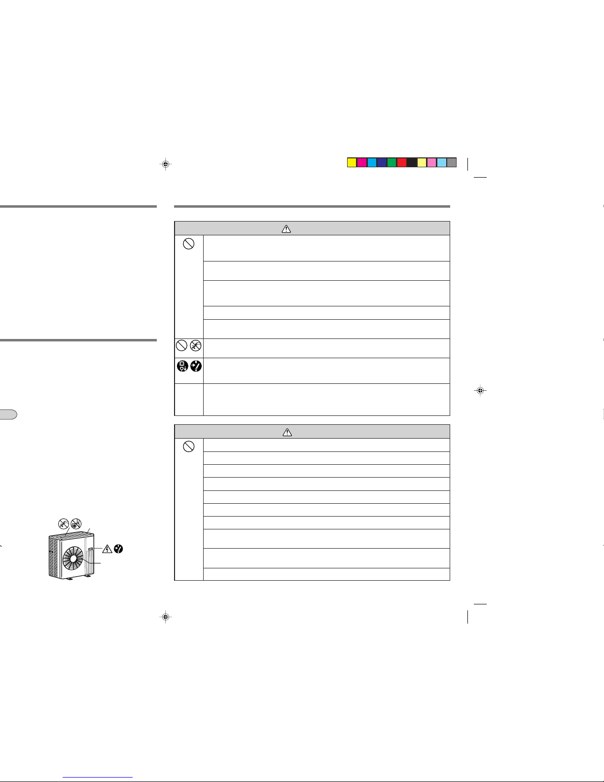
ENCLOSURE
AIR OUTLET
•
This air conditioner is NOT intended for use by children or infirm persons without supervisions.
Do not use intermediate connection of the power supply cord or the extension cord and do not
connect many devices to one AC outlet.
• A fire or an electric shock may result from poor contact, poor insulation, exceeding the permissible
current, etc.
Do not scratch or process the power supply cord, etc.
• Do not put heavy object on the power supply cord and do not scratch or process the cord. The cord may
be damaged and this may cause a fire or an electric shock.
Do not turn the breaker off/on or disconnect/connect the power supply plug during operation.
• This may cause a fire due to spark, etc.
• Be sure to turn off the breaker or disconnect the power supply plug absolutely after switching the indoor
unit off with the remote controller.
Do not expose your skin directly to cool air for a long time.
• This could damage your health.
The customer should not install this unit.
• If this is done incorrectly, it may cause a fire, an electric shock, or injury from the unit falling, water
leaking, etc. Consult your dealer.
Do not insert your finger or a stick, etc. into the air inlet/outlet.
• Since the fan rotates at high speed, this may cause an injury.
• Young children should be supervised to ensure that they do not play with the air conditioner.
When an abnormality (burning smell, etc.) occurs, stop the air conditioner and disconnect the power
supply plug or turn off the breaker.
• If the unit continues to be operated in an abnormal condition, it may cause a fire, trouble, etc. In this case,
consult your dealer.
Repairs or relocation should not be done by the customer.
• If this is done incorrectly, it may cause a fire, an electric shock, or injury from the unit falling, water
leaking, etc. Consult your dealer.
• If the power supply cord is damaged, it must be replaced by the manufacturer or its service agent in order
to avoid a hazard.
When the air filter is to be removed, do not touch the metal parts of the indoor unit.
• This may cause an injury.
Do not use an insecticide or flammable spray.
• This may cause a fire or deformation of the cabinet.
Do not put a pet or houseplant where it will be exposed to direct airflow.
• This could injure the pet or plant.
Do not leave the unit on an installation stand which is damaged.
• The unit may fall and this may cause an injury.
Do not step onto an unstable bench when maintaining the unit, etc.
• This may cause an injury, etc. if you fall down.
Do not pull the power supply cord.
• The core wire of the power supply cord may be disconnected and this may cause a fire.
Do not charge or disassemble the batteries and do not throw them into a fire.
• This may result in leakage, fire or an explosion.
Do not operate the unit for a long time in high humidity, e.g. leaving a door or window open.
• In the cooling mode, if the unit is operated in a room with high humidity (80% RH or more) for a long time,
water condensed in the air conditioner may drop and wet or damage furniture, etc.
Do not use the unit for special purposes.
• Do not use this air conditioner to preserve precision devices, food, animals, plants and art objects.
This may cause deterioration of quality, etc.
Do not put a stove, etc. where they are exposed to direct airflow.
• This may cause imperfect combustion.
WARNING
CAUTION
Page 3

3
NAME OF EACH PART
Indoor unit
Outdoor unit
Air cleaning filter
(White bellows
type) (OPTION)
Vertical vane
Operation section
(When the front panel is opened)
Front panel
Air inlet
to Breaker
Power supply cord
Remote control
receiving section
Display section
Emergency operation switch
Horizontal vane
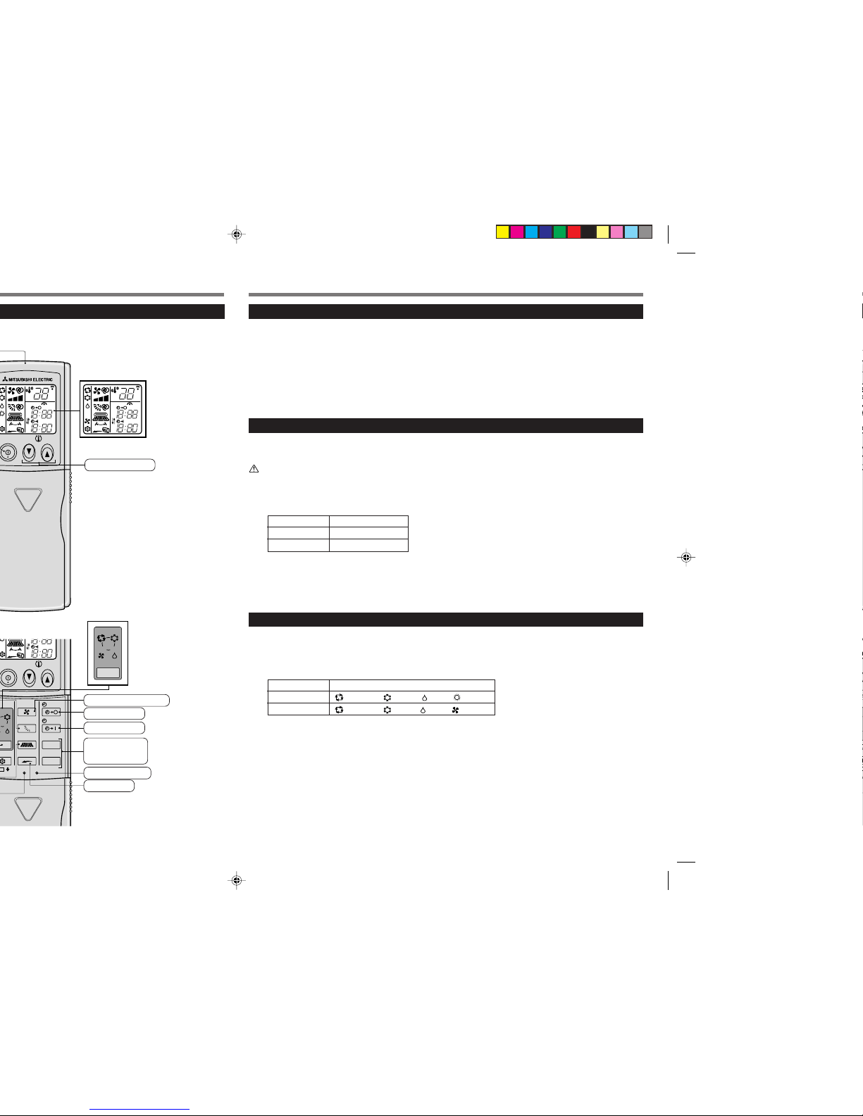
Remote controller
Operation Indicator
Remote control
receiving section
Operation
Indicator lamp
MUH-A24WV
MU-A30WV
MUH-A30WV
MU-A18WV
MUH-A18WV
MU-A24WV
Air inlet (back and side)
Piping
Drainage hose
Air outlet
Drain outlet
Catechin air filter
Page 4
FAN
TOO
WARM
TOO
COOL
VANE
STOP
START
HR.
MIN.
WIDE VANE
LONG
COOL
DRY
AMPM
CLOCK
˚C
AMPM
RESET CLOCK
MODE
I FEEL
COOL
DRYFAN
TOO
COOL
AMPM
CLOCK
˚C
AMPM
TOO
WARM
AMPM
CLOCK
˚C
AMPM
Temperature buttons
PREPARATION BEFORE OPERATION
Auto restart function
■
These models are equipped with an auto restart function. If you do not want to use this function,
please consult the service representative because the setting of the unit needs to be changed.
Auto restart function is ...
When the indoor unit is controlled with the remote controller, the operation mode, the set temperature and the fan speed are
stored in the memory. If a power failure occurs or the main power is turned off during operation, “Auto restart function” sets
automatically to start operating in the same mode as the one set with the remote controller just before the shutoff of the main
power. (Refer to page 6 for details.)
Indoor unit
■
Insert the power supply plug into the power outlet and/or turn the breaker on.
WARNING:
Remove dirt from the power supply plug and insert the plug securely.
If dirt adheres to the plug or insertion is incomplete, it may cause a fire or an electric shock.
■
Check the type of air conditioner.
Type Model Name
COOL & HEAT MSH-A18/24/30WV
COOL ONLY MS-A18/24/30WV
NOTE:
This operating instructions manual has different contents for the COOL & HEAT type air conditioner and
COOL ONLY type.
Follow the appropriate instructions for each type of air conditioner.
Remote controller
■
The remote controller used for the COOL ONLY type air conditioner is different from the one used
for the COOL & HEAT type as shown in the illustrations to the left.
Check the difference of operation mode.
Type Operation Mode
COOL & HEAT
(I FEEL...), (COOL), (DRY), (HEAT)
COOL ONLY
(I FEEL...), (COLL), (DRY), (FAN)
NOTE:
Only the remote controller for the COOL & HEAT type air conditioner is illustrated as an example in this operating
instructions manual.
Fan speed control button
CLOCK set button
Off-timer button
On-timer button
HR.button
MIN.button
(Time set buttons)
LONG button
In case of COOL ONLY type
(MS series)
In case of COOL ONLY type
(MS series)
Page 5
5
Remote controller holder
COOL & HEAT type (MSH series)
1 Press the EMERGENCY OPERATION switch.
• Each time the EMERGENCY OPERATION switch is
pressed, the unit will operate in order of EMERGENCY COOL MODE, EMERGENCY HEAT MODE
and STOP MODE.
However, when the EMERGENCY OPERATION
switch is once pressed, the unit will operate in test
run for 30 minutes and then the operation mode
shifts to EMERGENCY MODE.
• Details of EMERGENCY MODE are as shown below. However, the temperature control does not
work for 30 minutes in test run and the unit is set
to continuous operation. The fan speed is set to
High in test run and shifts to Medium after 30 minutes.
Operation mode COOL HEAT
Set temperature 24°C24°C
Fan speed Medium Medium
Horizontal vane Auto Auto
Vertical vane Front Front
• The operation mode is indicated by the Operation
Indicator lamp on the indoor unit as following figure.
Operation Indicator lamp
■
To stop the emergency operation, press the
EMERGENCY OPERATION switch once (in
case of EMERGENCY HEAT MODE) or twice
(in case of EMERGENCY COOL MODE).
When the remote controller cannot be used (emergency operation)
When the batteries of the remote controller run out or the remote controller malfunctions, the emergency operation
can be done using the EMERGENCY OPERATION switch.
COOL ONLY type (MS series)
1 Press the EMERGENCY OPERATION switch.
• When the EMERGENCY OPERATION switch is
pressed, the unit will operate in test run for 30 minutes at first and then the operation mode shifts to
EMERGENCY COOL MODE.
• Details of EMERGENCY COOL MODE are as shown
below. However, the temperature control does not
work for 30 minutes in test run and the unit is set to
continuous operation. The fan speed is set to High
in test run and shifts to Medium after 30 minutes.
Operation mode COOL
Set temperature 24°C
Fan speed Medium
Horizontal vane Auto
Vertical vane Front
• The operation mode is indicated by the Operation
Indicator lamp on the indoor unit as following figure.
Operation Indicator lamp
■
To stop the EMERGENCY COOL MODE, press
the EMERGENCY OPERATION switch again.
Each time the switch is pressed, the operation mode
alternates between the EMERGENCY COOL MODE
and STOP MODE.
EMERGENCY HEAT
EMERGENCY COOL
STOP
EMERGENCY COOL STOP
Handling of the remote controller
• The range that the signal can reach is about 6 m when
the remote controller is pointed at the front of the indoor unit.
• When a button is pressed, one or two beeps will be
heard from the indoor unit. If no sound is heard, operate again.
• Use the remote controller carefully.
If it is dropped, thrown or it gets wet, the remote controller may not operate.
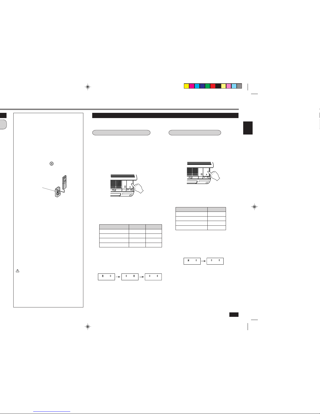
When installing on a wall, etc.
• Install the remote controller holder in a position where
the signal reception sound (beep) can be heard from
the indoor unit when the
ON/OFF
button is pressed.
How to install/remove the remote controller
Installing :Insert the remote controller downward.
Removing :Pull it up.
Dry-cell batteries
■ Reference for replacing batteries
Replace the batteries with new AAA alkaline batteries
in the following cases:
· When the indoor unit does not respond to the remote
control signal.
· When the display on the remote controller becomes
dim.
· When a button of the remote controller is pressed, all
displays appear on the screen, and then disappear
immediately.
Do not use manganese batteries. The remote controller
could malfunction.
• The service life of an alkaline battery is about 1 year.
However, a battery whose time limit is approaching
may be exhausted soon. The recommended usable
time limit is indicated (month/year) on the bottom of
the battery.
• To prevent liquid leakage, take out all batteries when
the remote controller is not going to be used for a
long time.
CAUTION:
If liquid from the batteries gets onto your skin or
clothes, wash it well with clean water.
If liquid from the batteries gets into your eyes, wash
them well with clean water and consult a doctor at
once.
• Do not use rechargeable batteries.
• Replace the 2 batteries with new ones of the same
type.
• Dispose of exhausted batteries in the correct manner.
Operation Indicator
Operation IndicatorOperation Indicator
Operation Indicator
Operation Indicator
Page 6

FAN
VANE
MODE
STOP
START
HR.
I FEEL
COOL
DRY
WIDE VANE
LONG
HEAT
Details of operation
According to the room temperature when the operation starts, the operation mode is automatically set to COOL, DRY or
HEAT. However, when operation is started again within 2 hours after it is stopped, the same operation mode before the
operation is stopped is selected. The operation mode selected first is not changed even if the room temperature changes.
If the operation mode does not match the room condition, select the appropriate operation mode by pressing the
MODE
button.
Details of auto operation
Operation state
This shows that the air conditioner is operating to reach the
target temperature. Please wait until the target temperature
is obtained.
This shows that the room temperature is approaching the
target temperature.
(In case of outdoor unit MXZ series only)
Please refer to Information for multi system air conditioner.
(Page 7)
Indication
Difference between target
temperature and room temperature
About 2°C or more
About 2°C or less
—
Description of “I FEEL...” mode
COOL & HEAT type (MSH series) COOL ONLY type (MS series)
Room temperature
Operation mode Target temperature Operation mode Target temperature
when started
(initial state) (initial state)
About 25°C or higher COOL About 24°C COOL About 24°C
About 25°C - 23°CDRY — DRY —
About 23°C or lower HEAT About 26°CDRY —
NOTE:
COOL: When the room temperature is 2°C higher than the set temperature, the set temperature may not be
changed since the air conditioner is operating to reach the target (set) temperature. In this case, please
wait until the room temperature drops to within 2°C of the set temperature and then change the set
temperature.
HEAT: When the room temperature is 2°C lower than the set temperature, the set temperature may not be
changed since the air conditioner is operating to reach the target (set) temperature. In this case, please
wait until the room temperature rises to within 2°C of the set temperature and then change the set
temperature.
Details of display on the indoor unit
The operation indicator at the right side of the indoor unit indicates the operation state.
Operation indicator lamp
Operation Indicator
Lighted
Blinking
Not lighted
ON/OFF
button.
ON/OFF
button.
TOO
WARM
button to lower the temperature.
TOO
COOL
button to raise the temperature.
MODE
Page 7

7
ON/OFF
FAN
TOO
WARM
TOO
COOL
VANE
MODE
ECONO COOL
STOP
START
HR.
MIN.
I FEEL
COOL
DRY
AMPM
CLOCK
˚C
AMPM
WIDE VANE
LONG
HEAT
RESET CLOCK
ON/OFF
button.
MODE
button.
Type Operation mode
ON/OFF
button.
ON/OFF
button.
AIR FLOW VELOCITY AND DIRECTION ADJUSTMENT
AIR FLOW velocity and direction can be selected as required.
■
To change the AIR FLOW velocity, press the
FAN
button.
Each time the button is pressed, the fan speed is changed in sequence:
(Low) → (Med.) → (High) → (AUTO)
• Use the
(High) notch to cool/heat the room more.
• If the operating sound of the air conditioner disturbs your sleep, use the
(Low) notch.
■
To change the AIR FLOW blowing direction vertically, press the
VANE
button.
Each time the button is pressed, the angle of the horizontal vane is changed in
sequence:
(1) → (2) → (3) → (4) → (5) → (SWING) → (AUTO)
SWING OPERATION
Use the swing operation for the air flow to reach all corners of the room.
Recommended horizontal vane range
Use the
(AUTO) position usually.
Use position
(1) or (2) in the COOL or DRY mode
and use positions
(3) to (5) in the HEAT mode
when adjusting to your requirements.
1
2
3
4
5
HEAT
NOTE:
• In the cooling operation, when the air conditioner is operated with setting the horizontal vane to
(4) or (5) for
1 hour, the AIR FLOW direction is automatically set to horizontal to prevent condensed water from dropping.
• Adjust the vertical AIR FLOW direction using the remote controller. If the horizontal vane is moved manually, it may
cause trouble.
• In the heating operation, if the air flow temperature is too low or when defrosting is being done, the horizontal vane
position is set to
(1).
COOL
DRY
Auto air flow direction control operation
When the AUTO mode is selected with the
VANE
button, the position of the horizontal vane is automatically set to
correspond to the operation mode for effective operation.
(1) HEAT: When the air flow temperature is too low, the air is blown out horizontally.
When the air flow temperature rises, the air is blown out downwards.
(2) COOL, DRY: The air is blown out horizontally.
(3) FAN: The air is blown out downwards.
■
To change the AIR FLOW blowing direction horizontally, press the
WIDE VANE
button.
Each time the button is pressed, the angle of the VERTICAL VANE is changed in sequence:
→ → → → (SWING) → →
SWING OPERATION
Use the swing operation for the air flow to reach all corners of the room.
Horizontal AIR FLOW blowing range
NOTE:
Adjust the horizontal AIR FLOW direction using the remote controller. If the VERTICAL VANE is moved manually, it may cause trouble.
About 100°
COOL/DRY
HEAT
About 150°
Page 8

ECONO COOL OPERATION
Use this operation when you want to be comfortable in COOL mode even with energy saved.
TIMER OPERATION (ON/OFF TIMER)
It is convenient to set the timer when you go to bed, when you get home, when you get up, etc.
How to set the ON timer
1 Press the
START
button during operation.
Each time the button is pressed, the ON timer mode
alternates between ON and OFF.
2 Set the time of the timer using the
HR.
and
MIN.
buttons.
Each time the
HR.
button is pressed, the set time in-
creases by 1 hour; each time the
MIN.
button is pressed,
the set time increases by 10 minutes.
To release the ON timer:
■
Press the
START
button.
How to set the OFF timer
1 Press the
STOP
button during operation.
Each time the button is pressed, the OFF timer mode
alternates between ON and OFF.
2 Set the time of the timer using the
HR.
and
MIN.
buttons.
Each time the
HR.
button is pressed, the set time in-
creases by 1 hour; each time the
MIN.
button is pressed,
the set time increases by 10 minutes.
To release the OFF timer:
■
Press the
STOP
button.
Perform the following operations while the unit is operating in the MANUAL COOL mode.
■
Press the
ECONO COOL
button.
When the (ECONO COOL) operation is selected in COOL mode, the air
conditioner performs swing operation in various cycle according to the temperature of air conditioner.
Also SET TEMPERATURE is automatically set 2°C higher than in COOL mode.
To release the ECONO COOL operation:
■
Press the
ECONO COOL
button again.
○○○○○○○○○○○○○○○○○○○○○○○○○○○○○○○○
• When the
VANE
button or the
LONG
button is pressed or the operation mode
is changed during the ECONO COOL operation, ECONO COOL operation
is released.
• The
FAN
button, the
TOO
WARM
or
TOO
COOL
button and ON/OFF timer (explained below)
are available.
Programming timer operation
The ON timer and the OFF timer can be used in combination. The timer of the set time that is reached first will operate first.
(“ ” mark indicates the order of timer operations.)
• If the current time has not been set, the timer operation cannot be used.
NOTE:
If the main power is turned off or a power failure occurs while AUTO START/STOP timer is active, the timer setting is
cancelled. As these models are equipped with an auto restart function, the air conditioner starts operating with timer
cancelled at the same time that power is restored.
What is “ECONO COOL”?
Swing air flow (change of air flow) makes you feel cooler than constant air flow. So, even though the set temperature is
automatically set 2°C higher, it is possible to perform cooling operation with keeping comfort. As a result, energy can be saved.
LONG
button.
(AUTO), the fan speed is higher than a fan
(front).
COOL/DRY HEAT/FAN
LONG
button again.
VANE
button
ECONO COOL
button (only during COOL mode)
FAN
button to set the fan speed to (High), and
LONG
button.
, and
WIDE VANE
buttons, temperature buttons and the ON/OFF timer
ON/OFF
FAN
TOO
WARM
TOO
COOL
VANE
MODE
ECONO COOL
STOP
START
HR.
MIN.
I FEEL
COOL
DRY
AMPM
CLOCK
˚C
AMPM
WIDE VANE
LONG
HEAT
RESET CLOCK
Page 9

9
When the air conditioner is to be used
again:
1 Clean the air filter and install it in the indoor
unit.
(Refer to page 10 for cleaning instructions.)
2 Check that the air inlet and outlet of the in-
door/outdoor units are not blocked with any
obstacles.
3 Check that the earth is connected correctly.
CAUTION:
Earth the unit.
Do not connect the earth to a gas pipe, water pipe, lightning rod or the earth of a telephone. If the earthing is
incorrect, it may cause an electric shock.
MAINTENANCE
Before starting maintenance
■
Turn off the breaker and/or disconnect the
power supply plug.
CAUTION:
When the unit is to be cleaned, switch it off and disconnect the power supply plug or turn off the breaker. Since
the fan rotates at high speed during operation, it may
cause an injury.
Cleaning the indoor unit
■
Clean the unit using a soft dry cloth.
• If the dirt is noticeable, wipe the unit with a cloth
soaked in a solution of mild detergent diluted in lukewarm water.
• Do not use gasoline, benzine, polishing powder, or
insecticide. The unit may be damaged.
Do not open the front panel up past the level position.
The panel may come off in order to prevent it from being damaged.
• The front panel may also come off if the upper part of the front panel is pulled down.
Do not exceed.
Movable
range
■
If the front panel comes off, attach it as explained below.
Keeping the front panel level with one hand, insert the hinges one by one with the other hand
into the notches at the left, right and center of the top of the indoor unit until they click into
place. (1) Then, close the front panel. (2)
1
2
Keep the front panel level and
insert the hinges into the notches.
• Do not step onto an unstable bench when maintaining the unit, etc. This may cause an injury, etc. if you fall
down.
CAUTION
Page 10

Air cleaning filter replacement
1 Remove the catechin air filter.
2 Remove the air cleaning filter (White bellows
type).
REPLACEMENT OF THE AIR CLEANING FILTER (OPTION)
When the capacity is lowered because of dirt, etc., it is necessary to replace the air cleaning filter.
Catechin air filter
3 After washing with water/lukewarm water,
dry the catechin air filter well in the shade.
• Do not expose the catechin air filter to direct sunlight or heat from a fire when drying it.
4 Install the catechin air filter.
About once every 4 months
1 Install a new air cleaning filter.
2 Install the catechin air filter and securely
close the front panel.
○○○○○○○○○○○○○○○○○○○○○○○○○○○○○○○○○○○○○○○○○○○○○○○○○
Air cleaning filter
• If the air cleaning filter is clogged, it may lower the unit’s capacity or cause condensation at the air outlet.
• The air cleaning filter is disposable. The standard usable term is about 4 months. However, if the colour of the filter turns
to dark brown, replace the filter at once.
Optional parts Optional parts are available from your local dealer.
Name of parts AIR CLEANING FILTER
Parts number MAC-1700FT
• Please purchase the optional parts (MAC-1700FT) as a set (2 pcs) for the first time use.
Install.
Air cleaning filter
Page 11

11
Question
The air conditioner cannot
be operated for about 3 minutes when restarted.
Cracking sound is heard.
The air from the indoor unit
smells strange.
The fan stops during the
DRY operation.
The sound of water flowing
is heard.
The sound as burbling is
heard.
The room cannot be cooled
sufficiently.
Mist is discharged from the
air outlet of the indoor unit.
The air flow direction
changes during operation.
The direction of the horizontal vane cannot be adjusted with the remote controller.
Answer (not a malfunction)
• This protects the air conditioner according to instructions from the microprocessor. Please wait.
• This sound is generated by the expansion/contraction of the front panel, etc. due to change in
temperature.
• The air conditioner may suck in an odor adhering to the wall, carpet, furniture, cloth, etc. and
blow it out with the air.
• In DRY operation, the unit operates using the
same refrigerant circuit as in COOL operation.
DRY operation time has to be reduced in order
to lower humidity without much room temperature decreasing. So the compressor sometimes
stops, and at the same time the indoor fan stops.
This prevents water condensed on the heat exchanger from evaporating again.
• This is the sound of refrigerant flowing inside the
air conditioner.
• This is the sound of condensed water flowing in
the heat exchanger.
• This is the sound of the heat exchanger defrosting.
• This sound is heard when the outside air is absorbed from the drain hose in turning on the
range hood or the ventilation fan and that makes
water flowing in the drain hose spout out.
This sound is also heard when the outside air
blows into the drain hose in case the outside wind
is strong.
• When a ventilation fan or a gas cooker is used
in a room, the cooling load increases, resulting
in an insufficient cooling effect.
• When the outside air temperature is high, the
cooling effect may not be sufficient.
• The cool air from the air conditioner rapidly cools
moisture in the air inside the room, and it turns
into mist.
• When the air conditioner is operated in COOL
or DRY mode, if the operation continues with air
blowing down for 1 hour, the direction of the air
flow is automatically set to horizontal to prevent
condensed water from dropping.
• In the heating operation, if the air flow temperature is too low or when defrosting is being done,
the horizontal vane position is automatically set
to horizontal.
WHEN YOU THINK THAT TROUBLE HAS OCCURRED
Question
Water leaks from the outdoor unit.
White smoke is discharged
from the outdoor unit.
Air does not blow out soon
in the heating operation.
The operation is stopped
for about 10 minutes in the
heating operation.
Hissing sound is sometimes heard.
The room cannot be heated
sufficiently.
The swing operation of the
VERTICAL VANE is suspended for about 15 seconds, then restarted.
In a multi-unit system, the
indoor unit which is not operating becomes warm and
a sound, similar to water
flowing, is heard from the
unit.
The air conditioner starts
the operation only with the
main power turned on,
though you do not operate
the unit with the remote
controller.
Answer (not a malfunction)
• During COOL and DRY operations, pipe or pipe
connecting sections are cooled and this causes
water to condense.
• In the heating operation, the defrosting operation makes water frozen on the outdoor unit melt
and drip down.
• In the heating operation, water condensed on
the heat exchanger drips down.
• In the heating operation, vapor generated by the
defrosting operation looks like white smoke.
• Please wait as the air conditioner is preparing
to blow out warm air.
• Defrosting of the outdoor unit is being done (Defrosting operation).
Since this is completed in 10 minutes, please
wait. (When the external temperature is too low
and humidity is too high, frost is formed.)
• This is the sound when the flow of refrigerant
inside the air conditioner is switched.
• When the outside air temperature is low, the
heating effect may not be sufficient.
• This is for the swing operation of the VERTICAL
VANE to be performed normally.
• A small amount of refrigerant continues to flow
into the indoor unit even though it is not operating.
• These models are equipped with an auto restart
function. When the main power is turned off without stopping the air conditioner with the remote
controller and is turned on again, the air conditioner will start operation automatically in the
same mode as the one set with the remote controller just before the shutoff of the main power.
Page 12

CAUTION:
• Earth the unit.
Do not connect the earth to a gas pipe, water pipe, lightning rod or the earth of a telephone. If the earthing is
incorrect, it may cause an electric shock.
• Install an earth leakage breaker depending on the place where the air conditioner is to be installed (humid places,
etc.).
If the earth leakage breaker is not installed, it may cause an electric shock.
Inspection and maintenance
• When the air conditioner is used for several seasons, the capacity may be lowered due to dirt inside the unit.
• Depending on the condition, an odor may be generated or dehumidified water may not drain out smoothly due to dirt,
dust, etc.
• It is recommended that the unit be inspected and maintained (charged) by specialist in addition to normal maintenance.
Consult your dealer.
Operating sound considerations
• Do not put an object around the air outlet of the outdoor unit. This may lower the capacity or increase the volume of the
operating sound.
• If an abnormal sound is heard during operation, consult your dealer.
Relocation
• When the air conditioner is to be removed or re-installed because of rebuilding, moving, etc., special techniques and work
are required.
WARNING :
Repairs or relocation should not be done by the customer.
If this is done incorrectly, it may cause a fire, an electric shock, or an injury from the unit falling, water leaking, etc.
Consult your dealer.
Disposal
To dispose of this product, consult your dealer.
If you have any questions, consult your dealer.
To prevent the effects
of a fluorescent lamp,
keep as far apart as
possible.
wall, etc.
Inverter-type
fluorescent lamp
Keep a space
to prevent the
picture
distortion or
the noise.
1 m
or more
Radio
100 mm or
more
Wellventilated
dry place
500 mm or
more
TV
Cordless
phone or
Portable
phone
3 m
or more
1 m
or more
NOTE:
1. Rating condition
Cooling — Indoor: 27°C DB, 19°C WB
Outdoor: 35°C DB
Heating — Indoor: 20°C DB
Outdoor: 7°C DB, 6°C WB
2. Guaranteed operating range
Indoor Outdoor
Upper limit
32°C DB 43°C DB
Cooling
23°C WB —
Lower limit
21°C DB 21°C DB
15°C WB —
Upper limit
27°C DB 24°C DB
Heating
— 18°C WB
Lower limit
20°C DB -10°C DB
— -11°C WB
* The required space depends on the type of outdoor unit.
The installation location of the outdoor unit should be at least
3 m away from the antennas for TV sets, radios, etc. In areas
where the reception is weak, provide greater space between
the outdoor unit and the antenna of the affected device if operation of the air conditioner interferes with radio or TV reception.
Cooling Cooling Heating Cooling Heating Cooling Heating
~ /N, 230V, 50Hz
5.0 6.5 8.5 5.0 5.2 6.3 7.2 8.5 9.4
1.81 2.48 3.26 1.78 1.61 2.41 2.48 3.26 3.43
16
44 60 75 47 74 77
1.40 1.90 2.30 1.75 2.15 2.30
IP20
IP24
1.64
4.15
52 53 55 52 53 55
Page 13

Page 14

Page 15

HEAD OFFICE: MITSUBISHI DENKI BLDG., 2-2-3, MARUNOUCHI, CHIYODA-KU, TOKYO 100-8310, JAPAN
SG79Y259H03
89/336/ EEC
 Loading...