


GENERAL
00-1
CONTENTS
HOW TO USE THIS MANUAL 2..............
Scope of Maintenance, Repair and Servicing
Explanations 2.................................
Definition of Terms 2...........................
Indication of Tightening Torque 2................
Model Indications 3............................
Explanation of Manual Contents 4...............
HOW TO USE
TROUBLESHOOTING/INSPECTION SERVICE
POINTS 6....................................
Troubleshooting Contents 6.....................
Diagnosis Function 7...........................
How to Use the Inspection Procedures 9........
Connector Measurement Service Points 10.......
Connector Inspection 11........................
Inspection Service Points for a Blown Fuse 12...
Points to Note for Intermittent Malfunctions 12....
VEHICLE IDENTIFICATION 13...............
Vehicle Information Code Plate 13...............
00109000829
Models 13.....................................
Model Code 15................................
Chassis Number 16............................
Engine Model Number 17.......................
MAJOR SPECIFICATIONS 18................
PRECAUTIONS BEFORE SERVICE 20.......
SUPPLEMENTAL RESTRAINT SYSTEM (SRS)
AND SEAT BELT WITH
PRE-TENSIONER 24.........................
SUPPORT LOCATIONS FOR LIFTING AND
JACKING 28................................
Support Positions for a Garage Jack and Axle
Stands 28.....................................
Support Positions for a Single-Post Lift or
Double-Post Lift 29.............................
Support Positions and Support Method for an
H-Bar Lift 30..................................
STANDARD PART/TIGHTENING-TORQUE
TABLE 32..................................

00-2
GENERAL -
How to Use This Manual
HOW TO USE THIS MANUAL
SCOPE OF MAINTENANCE, REPAIR
AND SERVICING EXPLANATIONS
This manual provides explanations, etc. concerning
procedures for the inspection, maintenance, repair
and servicing of the subject model. Note, however,
that for engineand transmission-related component
parts, this manual covers only on-vehicle
inspections, adjustments, an d the removal and
installation procedures for major components.
For detailed information concerning the inspection,
checking, adjustment, disassembly and reassembly
of the engine, transmission and major components
after they have been removed from the vehicle,
please refer to separate manuals covering the
engine and the transmission.
ON-VEHICLE SERVICE
“On-vehicle Service” is procedures for performing
inspections and adjustments of particularly
important locations with regard to the construction
and for maintenance and servicing, but other
inspection (for looseness, play, cracking, damage,
etc.) must also be performed.
INSPECTION
Under this title are presented inspection and
checking procedures to be performed by using
special tools and measuring instruments and by
feeling, but, for actual maintenance and servicing
procedures, visual inspections should always be
performed as well.
00100010302
DEFINITION OF TERMS
STANDARD VALUE
Indicates the value used as the standard for judging
the quality of a part or assembly on inspection
or the value to which the part or assembly is
corrected and adjusted. It is given by tolerance.
LIMIT
Shows the standard for judging the quality of a
part or assembly on inspection and means the
maximum or minimum value within which the part
or assembly must be kept functionally or in strength.
It is a value established outside the range of
standard value.
REFERENCE VALUE
Indicates the adjustment value prior to starting the
work (presented in order to facilitate assembly and
adjustment procedures, and so they can be
completed in a shorter time).
CAUTION
Indicates t h e presentation of information particularly
vital to t he worker during the performance of
maintenance and servicing procedures in order to
avoid the possibility of injury to the worker, or
damage to component parts, or a reduction of
component or vehicle function or performance, etc.
INDICATION OF TIGHTENING TORQUE
The tightening torque shown in this manual is a
basic value with a tolerance of ±10% except the
following cases when the upper and lower limits
of tightening torque are given.
(1) The tolerance of the basic value is within ±10%.
(2) Special bolts or the like are in use.
(3) Special tightening methods are used.

GENERAL -
How to Use This Manual
MODEL INDICATIONS
The following abbreviations are used in this manual for classification of model types.
1800: Indicates models equipped with the 1,800 mL <4G93> petrol engine.
2400: Indicates models equipped with the 2,400 mL <6G64> petrol engine.
GDI: Indicates the gasoline direct injection.
M/T: Indicates the manual transmission, or models equipped with the manual transmission.
A/T: Indicates the automatic transmission, or models equipped with the automatic transmission.
A/C: Indicates the air conditioner.
00-3
00-4
GENERAL -
How to Use This Manual
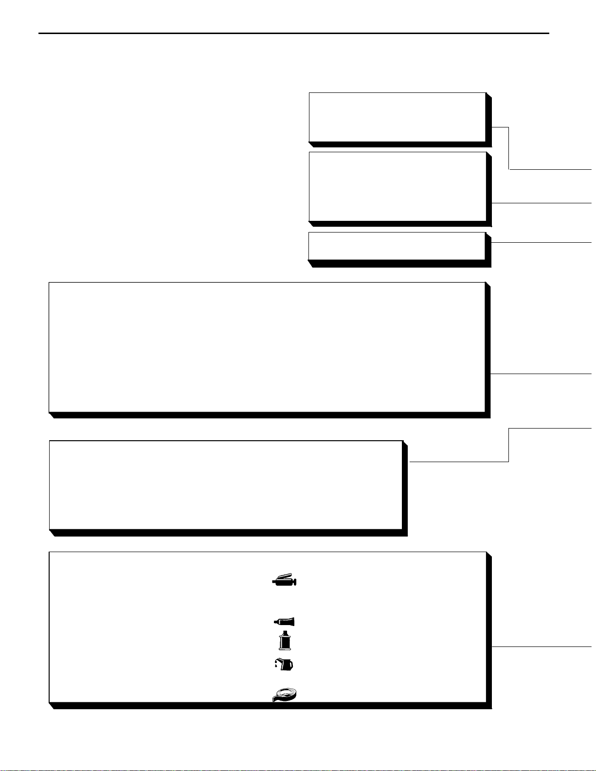
EXPLANATION OF MANUAL CONTENTS
Maintenance and Servicing Procedures
The numbers provided within the diagram indicate the sequence for maintenance and servicing procedures.
D Removal steps:
The part designation number corresponds
to the number in the illustration to indicate
removal steps.
D Disassembly steps:
The part designation number corresponds
to the number in the illustration to indicate
disassembly steps.
Indicates procedures to be performed
before the work in that section is started,
and procedures to be performed after
the work in that section is finished.
Component Diagram
A diagram of the component parts is
provided near the front of each section
in order to give a reader a better understanding of the installed condition of
component parts.
Indicates (by symbols) where lubrication is necessary.
D Installation steps:
Specified in case installation is impossible
in reverse order of removal steps. Omitted
if installation is possible in reverse order of
removal steps.
D Reassembly steps:
Specified in case reassembly is impossible
in reverse order of disassembly steps.
Omitted if reassembly is possible inreverse
order of disassembly steps.
Classifications of Major Maintenance/Service Points
When there are major points relative to maintenance and servicing procedures
(such as essential maintenance and service points, maintenance and service standard values, information regarding the use of special tools, etc.), these are arranged together as major maintenance and service points and explained in detail.
AA" : Indicates that there are essential points for removal or disassembly.
"AA : Indicates that there are essential points for installation or reassembly.
Symbols for Lubrication, Sealants and Adhesives
Information concerning the locations for lubrication and for application of sealants and adhesives is provided, by using symbols, in the diagram of component parts or on the page following the component parts page, and explained.
: Grease
(multipurpose grease unless there is a
brand or type specified)
: Sealant or adhesive
: Brake fluid or automatic transmission fluid
: Engine oil, gear oil or air conditioner compressor oil
: Adhesive tape or butyl rubber tape
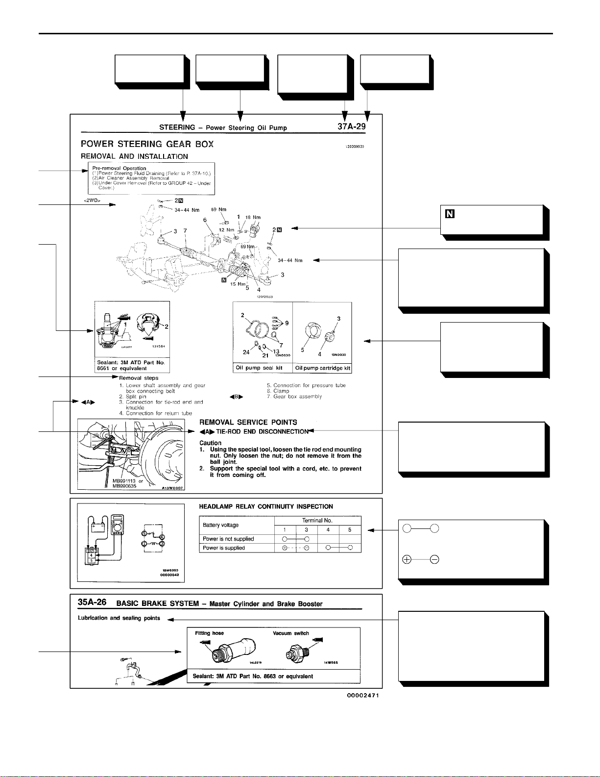
GENERAL -
How to Use This Manual
00-5
Indicates the
group title.
Indicates the
section title.
Indicates the
group number.
Indicates the
page number.
Denotes non-reus-
able part.
Denotes tightening torque.
For bolts and nuts which do not
have a tightening torque listed,
refer to the “Standard Partstightening-torque Table”.
Repair kit or set parts
are shown. (Only very
frequently used parts
are shown.)
Operating procedures, cautions, etc. on removal, installation, disassembly and reassembly are described.
indicates that there is
a continuity between the terminals.
indicates terminals to
which battery voltage is applied.
The title of the page (following
the page on which the diagram
of component parts is presented) indicating the locations of
lubrication and sealing procedures.
00-6
GENERAL -
How to Use Troubleshooting/Inspection Service Points
HOW TO USE TROUBLESHOOTING/INSPECTION SERVICE
POINTS
Troubleshooting of electronic control systems for which the MUT-II can be used follows the basic outline
described below. Furthermore, even in systems for which the MUT-II cannot be used, part of these systems
still follow this outline.
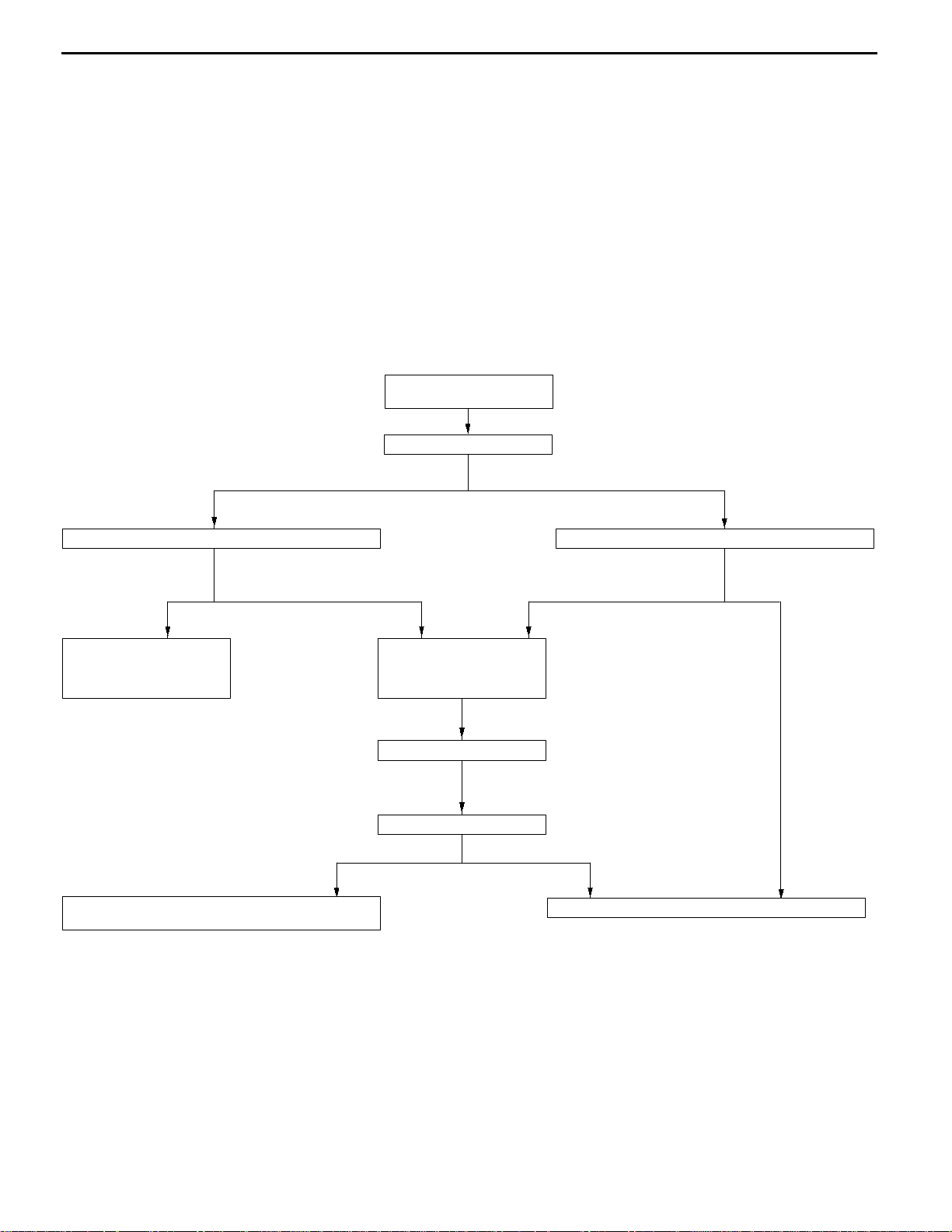
TROUBLESHOOTING CONTENTS
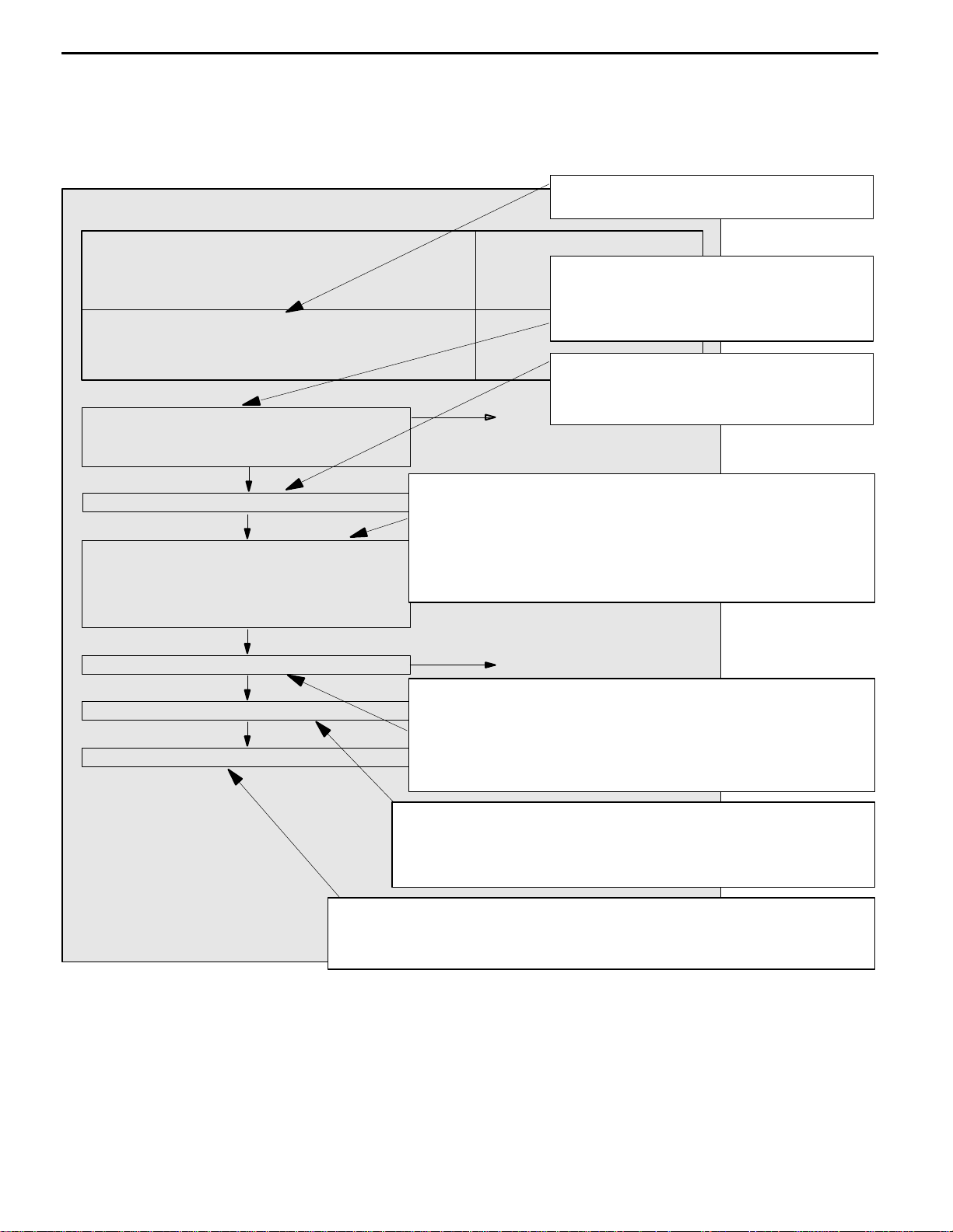
1. STANDARD FLOW OF DIAGNOSIS TROUBLESHOOTING
The troubleshooting sections follow the basic diagnosis flow which is given below. If the diagnosis
flow is different from that given below, or if additional explanation is required, the details of such
differences or additions will also be listed.
Diagnosis method
Gathering information
from the customer.
Check trouble symptom.
Reoccurs Does not reoccur.
00100020152
Read the diagnosis code
No diagnosis code
or communication
with MUT-IInot
possible
Refer to the INSPECTION
CHART FOR TROUBLE
SYMPTOMS (Refer to
applicable group.)
Diagnosis code
displayed.
Refer to the INSPECTION CHART FOR DIAGNOSIS
CODES (Refer to applicable group.)
Diagnosis code
displayed.
After taking note of the
malfunction code, erase
the diagnosis code
memory
Recheck trouble symptom.
Read the diagnosis codes.
Read the diagnosis code
Diagnosis code
displayed.
No diagnosis
code
INTERMITTENT MALFUNCTIONS (Refer to P.00-12.)
No diagnosis
code
2. SYSTEM OPERATION AND SYMPTOM VERIFICATION TESTS
If verification of the trouble symptoms is difficult, procedures for checking operation and verifying
trouble symptoms are shown.
3. DIAGNOSIS FUNCTION
Details which are different from those in the “Diagnosis Function” section on the next page are listed.
GENERAL -
4. INSPECTION CHART FOR DIAGNOSIS CODES
5. INSPECTION PROCEDURE FOR DIAGNOSIS CODES
Indicates the inspection procedures corresponding to each diagnosis code. (Refer to P.00-9 for how
to use the inspection procedures.)
6. INSPECTION CHART FOR TROUBLE SYMPTOMS
If there are trouble symptoms even though the results of inspection using the MUT-II show that all
diagnosis codes are normal, inspection procedures for each trouble symptom will be found by means
of this chart.
7. INSPECTION PROCEDURE FOR TROUBLE SYMPTOM
Indicates the inspection procedures corresponding to each trouble symptoms classified in the Inspection
Chart for Trouble Symptoms. (Refer to P.00-9 for how to use the inspection procedures.)
8. SERVICE DATA REFERENCE TABLE
Inspection items and normal judgement values have been provided in this chart as reference information.
9. CHECK AT ECU TERMINALS
Terminal numbers for the ECU connectors, inspection items and standard values have been provided
in this chart as reference information.
How to Use Troubleshooting/Inspection Service Points
00-7
10. INSPECTION PROCEDURES USING AN OSCILLOSCOPE
When there are inspection procedures using an oscilloscope, these are listed here.
DIAGNOSIS FUNCTION
METHOD OF READING DIAGNOSIS CODES
II
MUT-
WHEN USING THE MUT-
Connect the MUT-II to the diagnosis connector and take a
reading of the diagnosis codes.
Caution
II
Turn off the ignition switch before connecting or
disconnecting the MUT-II.
00-8
Diagnosis connector
GENERAL -
How to Use Troubleshooting/Inspection Service Points
MB991529
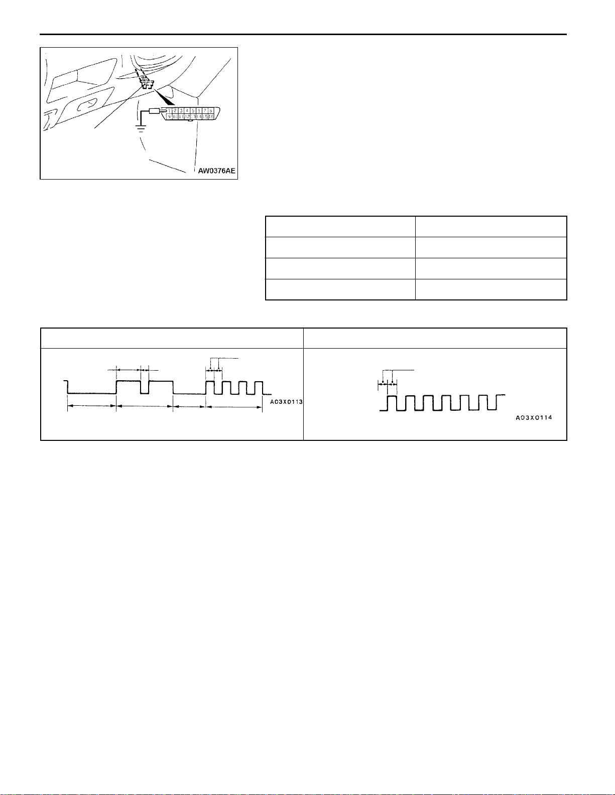
WHEN USING THE WARNING LAMP
1. Use the special tool to earth No.1 terminal (diagnosis
control terminal) of the diagnosis connector.
2. To check ABS system, remove the valve relay.
NOTE
That is because the valve relay is off and the warning
lamp remains illuminated if there is a fault in the ABS
system.
3. Turn on the ignition switch.
4. Read out a diagnosis code by observing how the warning
lamp flashes.
Applicable systems
System name W arning lamp name
GDI Engine warning lamp
A/T Neutral position indicator lamp
ABS ABS warning lamp
Indication of diagnosis code by warning lamp
When the diagnosis code No.24 is output When no diagnosis code is output*
On
Off
1.5 secs.
Pause
time 3
secs.
Tens
signal
0.5 sec.
Place
division
2 secs.
Units
signal
0.5 sec.
On
Off
0.5 sec. <GDI, A/T>
0.25 sec. <ABS>
NOTE
*: Even if the ABS system is normal, removing the valve relay causes the diagnosis code No.52 to
be output.
METHOD OF ERASING DIAGNOSIS CODES
WHEN USING THE MUT-
II
Connect the MUT-II to the diagnosis connector and erase the diagnosis code.
Caution
Turn off the ignition switch before connecting or disconnecting the MUT-II.
WHEN NOT USING THE MUT-
II
1. Turn the ignition switch to OFF.
2. After disconnecting the battery cable from the battery (-) terminal for 10 seconds or more, reconnect
the cable.
3. After the engine has warmed up, run it at idle for about 15 minutes.
GENERAL -
How to Use Troubleshooting/Inspection Service Points
00-9
HOW TO USE THE INSPECTION PROCEDURES
The causes of a high frequency of problems occurring in electronic circuitry are generally the connectors,
components, the ECU and the harnesses between connectors, in that order. These inspection procedures
follow this order, and they first try to discover a problem with a connector or a defective component.
1. Comments on the diagnosis code or trouble
CHECKING PROCEDURE 4
D
Indicator does notturnon or offeven if control
mode switch is pressed.
D
Indicator switch should not be illuminated is
illuminated.
In the above cases, the ECS switch circuit is defective or the indicator
circuit is defective.
MUT-IIData list
17 Control mode selection switch
ECU switch component inspection (Refer to P.33-44.)
Measure at switch connector A-44
D
D
Check the following connector.
Check trouble symptom.
Replace the ECS-ECU.
Voltage changes between approx. 0V®approx.
OK:
2.5V®approx. 5V when the switch is operated.
NG
OK
Disconnect the connector, and measure at the harness
side.
Voltage between terminal 6 - earth and terminal 8 earth
Approx. 5V
OK:
OK
A-44
OK
OK
4. Indicates voltage and resistance to be measured at a particular
NG
OK
NG
5. Inspect the contact condition at each connector terminal.
Probable cause
connector.
(Refer to Connector Measurement Service Points.)
The connector position can be located in the wiring diagram in the
electrical wiring manual by means of this symbol.
Indicates operation and inspection procedures, inspection terminals
and inspection conditions.
Indicates the OK judgement conditions.
Repair
(Refer to Connector Inspection Service Points.)
The connector position can be located in the wiring diagram in the
electrical wiring manual by means of this symbol.
Caution
After carrying out connector inspection, always be sure to
reconnect the connector as it was before.
symptom above.
2. Indicates inspection carried out using the
MUT-II.
Indicates the operation and inspection procedures.
Indicates the OK judgement conditions.
3. Detailed inspection procedures (methods)
such as component inspection and circuit
inspection are listed on a separate page, and
are given here for reference.
6. Confirm that there are trouble symptoms. If trouble symptoms have
disappeared, the connector may have been inserted incorrectly and the
trouble symptom may have disappeared during inspection.
If it seems that trouble symptoms still remain, proceed to the next page of
instructions.
7. If trouble symptoms still remain up to this stage, there is a possibility that there is an
open or short circuit in the harness between the connectors, so check the harness.
Alternatively, the cause may be a defective ECU, so try replacing the ECU and check
if the trouble symptom disappears.
HARNESS INSPECTION
Check for an open or short circuit in the harness between the terminals which were defective according
to the connector measurements. Carry out this inspection while referring to the electrical wiring manual.
Here, “Check harness between power supply and terminal xx” also includes checking for blown fuses.
For inspection service points when there is a blown fuse, refer to “Inspection Service Points for a Blown
Fuse.”
MEASURES TO TAKE AFTER REPLACING THE ECU
If the trouble symptoms have not disappeared even after replacing the ECU, repeat the inspection procedure
from the beginning.
00-10
GENERAL -
How to Use Troubleshooting/Inspection Service Points
CONNECTOR MEASUREMENT SERVICE POINTS
Turn the ignition switch to OFF when connecting disconnecting
the connectors, and turn the ignition switch to ON when
measuring if there are no instructions to be contrary.
Extra-thin probe
Test bar
Connector
Inspection harness
for connector pin
contact pressure
Harness connector
IF INSPECTING WITH THE CONNECTOR CONNECTED
(WITH CIRCUIT IN A CONDITION OF CONTINUITY)
Waterproof Connectors
Be sure to use the special tool (harness connector). Never
insert a test bar from the harness side, because to do so
will reduce the waterproof performance and result in corrosion.
Ordinary (non-waterproof) Connectors
Check by inserting the test bar from the harness side. Note
that if the connector (control unit, etc.) is too small to permit
insertion of t h e test bar, it should not be forced; use a special
tool (the extra-thin probe in the harness set for checking
for this purpose.
IF INSPECTING WITH THE CONNECTOR DISCONNECTED
<When Inspecting a Female Pin>
Use the special tool (inspection harness for connector pin
contact pressure in the harness set for inspection).
The inspection harness for connector pin contact pressure
should be used. the test bar should never be forcibly inserted,
as it may cause a defective contact.
<When Inspecting a Male Pin>
Touch the pin directly with the test bar.
Caution
At this time, be careful not to short the connector pins
with the test bars. To do so may damage the circuits
inside the ECU.

GENERAL -
How to Use Troubleshooting/Inspection Service Points
00-11
Connector disconnected or improperly
connected
Defective connector contact
Harness wire breakage
at terminal section
Low contact pressure
CONNECTOR INSPECTION
VISUAL INSPECTION
D Connector is disconnected or improperly connected
D Connector pins are pulled out
D Due to harness tension at terminal section
D Low contact pressure between male and female terminals
D Low connection pressure due to rusted terminals or foreign
matter lodged in terminals
MB991219
CONNECTOR PIN INSPECTION
If the connector pin stopper is damaged, the terminal
connections (male and female pins) will not be perfect even
if the connector body is connected, and the pins may pull
out of the reverse side of th e connector. Therefore, gently
pull the harnesses one by one to make sure that no pins
pull out of th e connector.
CONNECTOR ENGAGEMENT INSPECTION
Use the special tool (connector pin connection pressure
inspection harness of the inspection harness set) to inspect
the engagement of the male pins and females pins. (Pin
drawing force : 1 N or more)

00-12
Battery
GENERAL -
How to Use Troubleshooting/Inspection Service Points
INSPECTION SERVICE POINTS FOR A BLOWN
FUSE
Remove the fuse and measure the resistance between the
load side of the fuse and the earth. Set the switches of all
0
W
circuits which are connected to this fuse to a condition of
continuity. If the resistance is almost 0 W at this time, there
is a short somewhere between these switches and the load.
If the resistance is not 0 W, there is no short at the present
time, but a momentary short has probably caused the fuse
to blow.
Fuse
Load
switch
Load
Connector
inspection
The main causes of a short circuit are the following.
D Harness being clamped by the vehicle body
D Damage to the outer casing of t he harness due to wear
or heat
D Water getting into the connector or circuitry
D Human error (mistakenly shorting a circuit, etc.)
POINTS TO NOTE FOR INTERMITTENT
MALFUNCTIONS
Intermittent malfunctions often occur under certain conditions,
and if these conditions can be ascertained, determining the
cause becomes simple. In order to ascertain the conditions
under which an intermittent malfunction occurs, first ask the
customer for details about the driving conditions, weather
conditions, frequency of occurrence a n d trouble symptoms,
and then try to recreate the trouble symptoms. Next, ascertain
whether the reason why the trouble symptom occurred under
these conditions is due to vibration, temperature or some
other factor. If vibration is thought to be the cause, carry
out t he following checks with the connectors and components
to confirm whether the trouble symptom occurs.
The objects to be checked are connectors and components
which are indicated by inspection procedures or given as
probable causes (which generates diagnosis codes or trouble
symptoms.)
D Gently shake the connector up, down an d to the left and
right.
D Gently shake the wiring harness up, down and to the
left and right.
D Gently rock each sensor and relay, etc. by hand.
D Gently shake the wiring harness at suspensions an d other
moving parts.
NOTE
If determining the cause is difficult, the flight recorder function
of the MUT-II can also be used.

GENERAL -
Vehicle Identification
00-13
VEHICLE IDENTIFICATION
00100540085
VEHICLE INFORMATION CODE PLATE
LOCATION
Vehicle information code plate is riveted on the toeboard
inside the engine compartment.
CODE PLATE DESCRIPTION
The plate shows model code, engine model, transmission
1
2
3
4
5
model, and body colour code.
No. Item Contents
1 MODEL N84W N84W: Vehicle model
LNUCL6
LNUCL6: Model series
2 ENGINE 4G64 Engine model
3 EXT A69A Exterior code
4 TRANS
AXLE
5 COLOR A69 50H 03V A69: Body colour code
INT OPT
F5M42 Transmission code
50H: Interior code
03V: Equipment code
For monotone colour vehicles, the body colour code shall
be indicated. For two-tone or three-way two-tone colour
vehicles, each colour code only shall be indicated in series.
MODELS
00100030223
<SPACE RUNNER>
Model code Engine model Transmission model Fuel supply system
N61W SNUCL6/R6 4G93-DOHC-GDI F5M42 (2WD-5M/T) GDI
(1,834 mL)
SNFCL6
SNUGL6
SRUCL6/R6 F4A42 (2WD-4A/T)
SRFCL6
SRUGL6

00-14
GENERAL -
Vehicle Identification
<SPACE WAGON>
Model code Engine model Transmission model Fuel supply system
N84W LNUCL6/R6 4G64-DOHC-GDI F5M42 GDI
(2,351 mL) (2WD-5M/T)
LNFCL6
LNUGL6
LNHCL6/R6
LNGCL6
LNHGL6
LRUCL6/R6 F4A42
(2WD-4A/T)
LRFCL6
LRUGL6
LRHCL6/R6
LRGCL6
LRHGL6
N94W LNUCL6/R6 W5M42
(4WD-5M/T)
LNFCL6
LNHCL6/R6
LNGCL6

GENERAL -
Vehicle Identification
00-15
1
23
MODEL CODE
No. Items Contents
1 Development N6: SPACE RUNNER
(2WD)
N8: SPACE WAGON
5
6
4
789
2 Engine type 1: 1,800 mL petrol engine
3 Body type W: Wagon
4 Body style S: 3-door station wagon
5 Transmission type N: 5-speed manual
6 Trim level U,F,H,G: GLX
7 Specification engine
feature
(2WD)
N9: SPACE WAGON
(Full time 4WD)
4: 2,400 mL petrol engine
L: 4-door station wagon
transmission
R: 4-speed automatic
transmission
C,G: GDI-DOHC
00100040257
8 Steering wheel location L: Left hand
R: Right hand
9 Destination 6: For Europe

00-16
GENERAL -
Vehicle Identification
CHASSIS NUMBER
The chassis number is stamped on the toeboard inside the
engine compartment.
12 3
No. Items Contents
5
4
6
7
89
10
00100560104
11
1 Fixed figure J Asia
2 Distribution channel M Japan channel
3 Destination A For Europe, right hand drive
B For Europe, left hand drive
4 Body style S 3-door station wagon
L 4-door station wagon
5 Transmission type N 5-speed manual transmission
R 4-speed automatic transmission
6 Development order N6 SPACE RUNNER (2WD)
N8 SPACE WAGON (2WD)
N9 SPACE WAGON (Full time 4WD)
7 Engine 1 4G93: 1,834 mL petrol engine
4 4G64: 2,351 mL petrol engine
8 Sort W Station wagon
9 Model year X 1999
10 Plant Z Okazaki Motor Vehicle Works
11 Serial number - -

GENERAL -
Vehicle Identification
00-17
<4G93>
<4G64>
ENGINE MODEL NUMBER
00100570107
1. The engine model number is stamped at the cylinder
block as shown in the following.
Engine model Engine displacement
4G93
4G64
1,834
2,351
2. The engine serial number is stamped near the engine
model number.
Engine serial number AA0201 to YY9999

00-18
GENERAL -
Major Specifications
MAJOR SPECIFICATIONS
<SPACE RUNNER>
5
2
Items
9
7
N61W
SNUCL6,
SNUCR6,
SNFCL6,
SNUGL6
Vehicle Overall length 1 4,290 4,290
dimensions
mm
Overall width 2 1,695 1,695
Overall height
(unladen)
3 1,650
1,680*
Wheelbase 4 2,550 2,550
Track-front 5 1,460 1,460
Track-rear 6 1,465 1,465
Overhang-front 7 890 890
Overhang-rear 8 850 850
Ground clear-
9 155 155
ance (unladen)
Vehicle Kerb weight 1,360 1,380
weight kg
Max. gross vehicle
1,880 1,880
weight
Max. axle weight
1,000 1,000
rating-front
Max. axle weight
900 900
rating-rear
Seating capacity 5 5
Engine Model No. 4G93 4G93
Total displacementmL1,834 1,834
4
1
8
N61W
SRUCL6,
SRUCR6,
SRFCL6,
SRUGL6
1,650
1,680*
00100080143
3
3*
6
Transmis- Model No. F5M42 F4A42
sion
Fuel system Fuel supply
Type 5-speed manual 4-speed automatic
Gasoline Direct Injection
system
*: Vehicles with roof rails

<SPACE WAGON>
5
GENERAL -
9
Major Specifications
4
87
00-19
3
3*
6
Items
2
N84W
LNUCL6,
LNUCR6,
LNFCL6,
LNUGL6
1
N84W
LNHCL6,
LNHCR6,
LNGCL6,
LNHGL6
N84W
LRUCL6,
LRUCR6,
LRFCL6,
LRUGL6
N84W
LRHCL6,
LRHCR6,
LRGCL6,
LRGHL6
N94W
LNUCL6,
LNUCR6,
LNFCL6
N94W
LNHCL6,
LNHCR6,
LNGCL6
Vehicle Overall length 1 4,600 4,600 4,600 4,600 4,600 4,600
dimensions
mm
Overall width 2 1,775 1,775 1,775 1,775 1,775 1,775
Overall height
(unladen)
3 1,650
1,690*
1,650
1,690*
1,650
1,690*
1,650
1,690*
1,650
1,690*
1,650
1,690*
Wheelbase 4 2,780 2,780 2,780 2,780 2,780 2,780
Track-front 5 1,500 1,500 1,500 1,500 1,500 1,500
Track-rear 6 1,535 1,535 1,535 1,535 1,535 1,535
Overhang-front 7 890 890 890 890 890 890
Overhang-rear 8 930 930 930 930 930 930
Ground clear-
9 155 155 155 155 155 155
ance (unladen)
Vehicle Kerb weight 1,510 1,510 1,530 1,530 1,610 1,610
weight kg
Max. gross vehicle
2,180 2,180 2,180 2,180 2,260 2,260
weight
Max. axle weight
1,070 1,070 1,070 1,070 1,090 1,090
rating-front
Max. axle weight
1,130 1,130 1,130 1,130 1,190 1,190
rating-rear
Seating capacity 7 6 7 6 7 6
Engine Model No. 4G64 4G64 4G64 4G64 4G64 4G64
Total displacementmL2,351 2,351 2,351 2,351 2,351 2,351
Transmis- Model No. F5M42 F5M42 F4A42 F4A42 W5M42 W5M42
sion
Fuel system Fuel supply
Type 5-speed
manual
Gasoline Direct Injection
5-speed
manual
4-speed
automatic
4-speed
automatic
5-speed
manual
5-speed
manual
system
*: Vehicles with roof rails

00-20
GENERAL -
Precautions Before Service
PRECAUTIONS BEFORE SERVICE
00100050229
SUPPLEMENTAL RESTRAINT SYSTEM (SRS), SEAT BELT WITH PRE-TENSIONER
1. Items to follow when servicing SRS
(1) Be sure to read GROUP 52B - Supplemental Restraint System (SRS).
For safe operations, please follow the directions and heed all warnings.
(2) Wait at least 60 seconds after disconnecting the battery cable before doing any further work.
The SRS system is designed to retain enough voltage to deploy the air bag even after the battery
has been disconnected. Serious injury may result from unintended air bag deployment if work
is done on the SRS system immediately after the battery cable is disconnected.
(3) Warning labels must be heeded when servicing or handling SRS components and seat belt with
pre-tensioner. Warning labels are located in th e following locations.
D Sun visor
D Glove box
D SRS air bag control unit
D Steering wheel
D Steering gear and linkage
D Air bag module (driver’s side and front passenger ’s side)
D Clock spring
D Seat belt with pre-tensioner
D Side air bag module
D Side impact sensor
(4) Always use the designated special tools an d test equipment.
(5) Store components removed from the SRS and seat belt with pre-tensioner in a clean and dry
place.
The air bag module and seat belt with pre-tensioner should be stored on a flat surface and
placed so that the pad surface is facing upward.
Do not place anything on top of it.
(6) Never attempt to disassemble or repair the SRS components (SRS air bag control unit, air bag
module, clock spring and side impact sensor) a nd seat belt with pre-tensioner.
(7) Whenever you finish servicing the SRS and seat belt with pre-tensioner, check the SRS warning
lamp operation to make sure that the system functions properly.
(8) Be sure to deploy the air bag and seat belt with pre-tensioner before disposing of the air bag
module and seat belt with pre-tensioner or disposing of a vehicle equipped with an air bag and
seat belt with pre-tensioner. (Refer to GROUP 52B - Air Bag Module and Seat Belt Pre-tensioner
Disposal Procedures.)
2. Observe the following when carrying out operations on places where SRS components and seat
belt with pre-tensioner are installed, including operations not directly related to the SRS air bag and
seat belt with pre-tensioner.
(1) When removing or installing parts do not allow any impact or shock to the SRS components
and seat belt with pre-tensioner.
(2) SRS components and seat belt with pre-tensioner should not be subjected to heat, so remove
the SRS components and seat belt with pre-tensioner before drying or baking the vehicle after
painting.
D SRS air bag control unit, air bag module, clock spring and side impact sensor: 93_C or more
D Seat belt with pre-tensioner 90_ C or more
After re-installing them, check the SRS warning lamp operation to make sure that the system
functions properly.

GENERAL -
Precautions Before Service
00-21
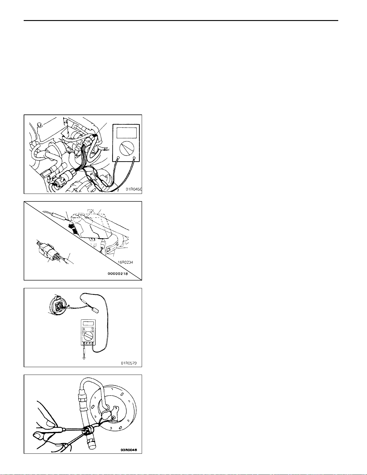
SERVICING THE ELECTRICAL SYSTEM
Before replacing a component related to the electrical system
and before undertaking any repair procedures involving the
electrical system, be sure to first disconnect the negative
(-) cable from the battery in order to avoid damage caused
by short-circuiting.
Caution
Beforeconnecting or disconnectingthe negative(-)cable,
be sure to turn off the ignition switch and the lighting
switch.
(If this is not done, there is the possibility of
semiconductor parts being damaged.)
APPLICATION OF ANTI-CORROSION AGENTS
AND UNDERCOATS
If oil or grease gets onto the oxygen sensor, it will cause
a drop in the performance of the sensor.
Cover the oxygen sensor with a protective cover when applying
anti-corrosion agents and undercoats.
Approx.
40 cm
PRE-INSPECTION CONDITION
“Pre-inspection condition” refers to the condition that the
vehicle must be in before proper engine inspection can be
carried out. If you see the words “Set the vehicle to the
pre-inspection condition”. in this manual, it means to set the
vehicle to the following condition.
D Engine coolant temperature: 80 - 90_C
D Lamps, electric cooling fan and all accessories: OFF
D M/T: Neutral
D A/T: P range
VEHICLE WASHING
If high-pressure car-washing equipment or steam car-washing
equipment is used to wash the vehicle, be sure to note the
following information in order to avoid damage to plastic
components, etc.
D Spray nozzle distance: Approx. 40 cm or more
D Spray pressure: 3,900 kPa or less
D Spray temperature: 82_C or less
D Time of concentrated spray to one point: within 30 sec.

00-22
GENERAL -
Precautions Before Service
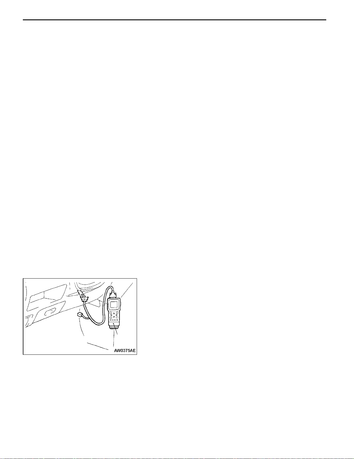
MUT-
II
sub-assembly
ROM pack
MUT-
MUT-II
Refer to the “MUT-II REFERENCE MANUAL” or “MUT-II
OPERATING INSTRUCTIONS” for instructions on handling
the MUT-II.
Connect the MUT-II to the diagnosis connector as shown
in the illustration.
Caution
Connection and disconnection of the MUT-IIshould
always be made with the ignition switch in the OFF
position.
II
IN ORDER TO PREVENT VEHICLES FROM FIRE
“Improper installation of electrical or fuel related parts could
cause a fire. In order to retain the high quality and safety
of the vehicle, it is important that any accessories that may
be fitted or modifications/repairs that may be carried out which
involve the electrical or fuel systems, MUST be carried out
in accordance with MMC’s information/Instructions”.
ENGINE OILS
Health Warning
Prolonged and repeated contact with mineral oil will result
in the removal of natural fats from the skin, leading to dryness,
irritation and dermatitis. In addition, used engine oil contains
potentially harmful contaminants which may cause skin cancer.
Adequate means of skin protection and washing facilities
must be provided.
Recommended Precautions
The most effective precaution is to adapt working practices
which prevent, as far as practicable, the risk of skin contact
with mineral oils, for example by using enclosed systems
for handling used engine oil and by degreasing components,
where practicable, before handling them.

GENERAL -
Precautions Before Service
Other precautions:
D Avoid prolonged and repeated contact with oils,
particularly used engine oils.
D Wear protective clothing, including impervious gloves
where practicable.
D Avoid contaminating clothes, particularly underpants, with
oil.
D Do n ot put oily rags in pockets, the use of overalls without
pockets will avoid this.
D Do not wear heavily soiled clothing a nd oil-impregnated
foot-wear. Overalls must be cleaned regularly an d kept
separately from personal clothing.
D Where there is a risk of eye contact, eye protection should
be worn, for example, chemical goggles or face shields;
in addition an eye wash facility should be provided.
D Obtain First Aid treatment immediately for open cuts and
wounds.
D Wash regularly with soap and water to ensure all oil is
removed, especially before meals (skin cleansers and
nail brushes will help). After cleaning, the application of
preparations containing lanolin to replace th e natural skin
oils is advised.
D Do not use petrol, kerosine, diesel fuel, gas oil, thinners
or solvents for cleaning skin.
D Use barrier creams, applying them before each work
period, to help the removal of oil from the skin after work.
D If skin disorders develop, obtain medical advice without
delay.
00-23

00-24
GENERAL -
Supplemental Restraint System (SRS) and Seat Belt with Pre-tensioner
SUPPLEMENTAL RESTRAINT SYSTEM (SRS) AND SEAT BELT
WITH PRE-TENSIONER
00100590073
To improve safety, the SRS and seat belts with
pre-tensioner are available as optional parts. These
systems enhance collision safety by restraining the
front passengers in case of an accident. The SRS
works with the pre-tensioner simultaneously when
a collision is detected.
The SRS consists of four air bag modules, SRS
air bag control unit (SRS-ECU), side impact sensor,
SRS warning lamp and clock spring. The air bags
are located in the centre of the steering wheel,
above the glove box, and built into the front seat
back assemblies. Each air bag has a folded air
bag and an inflator unit. The SRS-ECU under the
floor console monitors the system and has a safing
G sensor and an analog G sensor. The side impact
sensor inside the center pillar monitors any shocks
coming from the side of the vehicle. The warning
lamp on the instrument panel indicates the
SRS warning lamp
operational status of the SRS. The clock spring
is installed in the steering column.
The SRS side air bag deploys if an impact received
at the side of the vehicle is stronger than a certain
set value, in order to protect the upper bodies of
front seat passengers in the event of a collision.
The seat belt pre-tensioner is built into the front
seat belt retractor. Only authorized service
personnel should do work on or around the SRS
components a nd seat belt with pre-tensioner. Those
service personnel should read this manual carefully
before starting any such work. Extreme care must
be used when servicing the SRS to avoid injury
to the service personnel (by inadvertent deployment
of the air bags or inadvertent operation of the seat
belt with pre-tensioner) or the driver (by rendering
the SRS or the seat belt with pre-tensioner
inoperative).
Front passenger’s
side air bag module
Seat belt with
pre-tensioner
Driver’s side air bag
Front passenger’s
side air bag
Clock spring
Driver’s side
air bag module
Diagnosis
connector
SRS-ECU
Seat belt with pre-tensioner
Side air bag
module
Side impact sensor
Side air bag

GENERAL -
Supplemental Restraint System (SRS)
and Seat Belt with Pre-tensioner
SEAT BELT WITH PRE-TENSIONER
The seat belts with pre-tensioners are installed on
both center pillars.
The pre-tensioner, which is controlled by the SRSECU, works simultaneously with the SRS air bag
in a head-on collision. When triggered, the SRSECU sends a squib igniting signal to the gas generator. Generated gas moves the rotor to take up seat
00-25
belt slack. This prevents a passenger from moving
forwards excessively. After this, the ELR works to
inhibit the seat belt.
Caution
Never disassemble or give an impact to the
seat belt with pre-tensioner.
Seat belt
Rotor
SRS-ECU
SRS SERVICE PRECAUTIONS
1. In order to avoid injury to yourself or others
from accidental deployment of the air bag and
accidental operation of the seat belt with
pre-tensioner during servicing, read and
carefully follow all the precautions and
procedures described in this manual.
2. Do not use any electrical test equipment on
or near SRS components, except those
specified on GROUP 52B.
3. Never Attempt to Repair the Following
Components:
D SRS air bag control unit (SRS-ECU)
D Clock Spring
D Air bag module (Driver’s side or front
passenger’s side)
D Side air bag module
D Side impact sensor
D Seat belt with Pre-tensioner
Gas generator
00100600073
NOTE
If any of these components are diagnosed as
faulty, they should only be replaced, in
accordance with the INDIVIDUAL COMPONENTS SERVICE procedures in this
manual, starting at page GROUP 52B.

00-26
GENERAL -
Supplemental Restraint System (SRS)
and Seat Belt with Pre-tensioner
Insulating tape
SRS-ECU connector
Battery
4. Afterdisconnectingthe battery cable, wait60seconds
or more before proceeding with the following work.
The SRS system is designed to retain enough voltage
to deploy the air bag for a short time even after the
battery has been disconnected, so serious injury may
result from unintended air bag deployment if work is
done on the SRS system immediately after the battery
cables are disconnected.
5. Do not attempt to repair the wiring harness connectors
of the SRS. If any of the connectors are diagnosed as
faulty, replace the wiring harness. If the wires are
diagnosed as faulty, replace or repair the wiring harness
according to the following table.
SRS-ECU
Terminal No.
3 Instrument panel wiring harness®Earth Correct or replace each wiring
4 Instrument panel wiring harness®Combination meter
5, 6 Instrument panel wiring harness®Air bag module
7, 8 Instrument panel wiring harness®Clock spring Correct or replace the dash
9 Instrument panel wiring harness®Junction block (fuse No.8) Correct or replace each wiring
12 Instrument panel wiring harness®Junction block (fuse No.6)
16 Instrument panel wiring harness®Diagnosis connector
21, 22 Side air bag wiring harness®Side air bag module (L.H.)
23, 24 Side air bag wiring harness®Side air bag module (R.H.)
27, 28 Assist wiring harness
Destination of harness Corrective action
harness.
(SRS warning lamp)
(Front passenger’s side)
wiring harness. Replace the
clock spring.
harness.
®
Seat belt with pre-tensioner (Front
passenger’s side)
29, 30 Floor wiring harness®Seat belt with pre-tensioner (Driver’s side)
34, 36 Side air bag wiring harness®Floor wiring harness <L.H. drive
vehicles>, Assist wiring harness <R.H. drive vehicles>®Side
impact sensor (L.H.)
40, 42 Side air bag wiring harness®Assist wiring harness <L.H. drive
vehicles>, Floor wiring harness <R.H. drive vehicles>®Side
impact sensor (R.H.)

GENERAL -
Supplemental Restraint System (SRS)
and Seat Belt with Pre-tensioner
00-27
6. Inspection of the SRS-ECU harness connector <vehicles with SRS side air bag> should be carried
out by the following procedure.
Insert the special tool (narrow probe in the harness set) into connector from harness side (rear side),
and connect the tester to this probe. If any to other than the special tool is used, it may cause
damage to the harness and other components. Furthermore, measurement should not be carried
out by touching the probe directly against the terminals from the front of the connector. The terminals
are plated to increase their conductivity, so that if they are touched directly by the probe, the plating
may break, which will cause drops in reliability.
MB991222
SRS-ECU harness connector
SRS-ECU harness connector (rear side)
7. SRS components and seat belt with pre-tensioner should not be subjected to heat, so remove the
SRS-ECU, air bag module (driver’s side and front passenger’s side), clock spring, side impact sensor,
front seat assembly (side air bag module), and seat belt with pre-tensioner before drying or baking the
vehicle after painting.
D SRS-ECU, air bag module, clock spring, side impact sensor: 93_C or more
D Seat belt with pre-tensioner: 90_C or more
8. Whenever you finish servicing the SRS, check warning lamp operation to make sure that the system
functions properly. (Refer to GROUP 52B.)
9. Make certain that the ignition switch is OFF when the MUT-II is connected or disconnected.
10. If you have any questions about the SRS, please contact your local distributor.
NOTE
SERIOUS INJURY CAN RESULT FROM UNINTENDED AIR BAG DEPLOYMENT, SO USE ONLY
THE PROCEDURES AND EQUIPMENT SPECIFIED IN THIS MANUAL.

00-28
GENERAL -
Support Locations for Lifting and Jacking
SUPPORT LOCATIONS FOR LIFTING AND JACKING
Caution
Do not support the vehicles at locations other than specified supporting points. If do so, this
will cause damage, etc.
00100070065
SUPPORT POSITIONS FOR A GARAGE JACK AND AXLE STANDS
GARAGE JACK
Caution
Never support any point other than the specified one, or it will be deformed.
AXLE STANDS
Notch
Rubber
Notch
Rubber

GENERAL -
Support Locations for Lifting and Jacking
00-29
SUPPORT POSITIONS FOR A
SINGLE-POST LIFT OR DOUBLE-POST
LIFT
DOUBLE-POST LIFT
Notch
Caution
Whenserviceproceduresrequire removing rear
suspension, spare tyre and rear bumper, place
additional weight on rear end of vehicle or
anchor vehicle to hoist to prevent tipping of
centre of gravity changes.
Notch
SINGLE-POST LIFT

00-30
GENERAL -
Support Locations for Lifting and Jacking
Chassis-support position
(side sill)
H-bar lift
H-bar lift
Attachment
H-bar lift
Section A-A
Attachment
Side sill
H-bar lift
SUPPORT POSITIONS AND SUPPORT METHOD
FOR AN H-BAR LIFT
Caution
When service procedures require removing rear
suspension, fuel tank, spare tyre and rear bumper, place
additional weight on rear end of vehicle or anchor vehicle
to hoist to prevent tipping of centre of gravity changes.
When H-bar lift is used to lift up vehicles, use of metallic
attachment attached to the H-bar lift may cause damage
to the suspension arm etc. Therefore, lift up th e vehicle by
the following procedure.
1. Place the vehicle on the H-bar lift (same direction).
2. Place attachments on the H-bar lift at the designated
chassis-support positions. When making the attachments,
refer to the section concerning making them.
Caution
If support is at any location other than the designated
positions, the body or suspension might be deformed
or otherwise damaged, so care should be taken to
support only at the correct (designated) positions.
3. Raise the H-bar lift to the height at which the vehicle
is slightly raised and check to be sure that the vehicle
is correctly and sufficiently secured; then raise the vehicle.
A
A

GENERAL -
Support Locations for Lifting and Jacking
00-31
Block (A)
1,800
90
95
Block (B) Block (C)
15
40
60
100
Block (C)
40
100
15
20
40
140
40
40
mm
PREPARATION OF “ATTACHMENTS”
1. Prepare the blocks (wooden) and nails as shown in t he
figure.
Item Dimensions mm Quantity
Block (A) 90´95´1,800 2
Block (B) 60´100´95 4
Block (C) 140´40´95 8
Nail 70 or more 32
Caution
The wood selected for the blocks must be hard.
20
2. For the (B) blocks and (C) blocks, use a saw and chisel
or similar tool to make grooves of the dimensions shown
in the figure.
3. Make four “ATTACHMENTS” such as shown in the figure
nailing (B) and (C) blocks so that each (B) blocks is
sandwiches between (C) blocks.
140
Block (B)
Finished attachment
Block (C)
Nail
Movable according
to vehicle width

00-32
GENERAL -
Standard Part/Tightening-Torque Table
STANDARD PART/TIGHTENING-TORQUE TABLE
Each torque value in the table is a standard value
for tightening under the following conditions.
(1) Bolts, nuts and washers are all made of steel
and plated with zinc.
(2) The threads and bearing surface of bolts and
nuts are all in dry condition.
Standard bolt and nut tightening torque
Thread size Torque Nm
Bolt nominal
diameter (mm)
M5 0.8 2.5 4.9 5.9
M6 1.0 4.9 8.8 9.8
M8 1.25 12 22 25
M10 1.25 24 44 52
M12 1.25 41 81 96
Pitch (mm) Head mark “4” Head mark “7” Head mark “8”
The values in the table are not applicable:
(1) If toothed washers are inserted.
(2) If plastic parts are fastened.
(3) If bolts are tightened to plastic or die-cast
inserted nuts.
(4) If self-tapping screws or self-locking nuts are
used.
00100110033
M14 1.5 72 137 157
M16 1.5 111 206 235
M18 1.5 167 304 343
M20 1.5 226 412 481
M22 1.5 304 559 647
M24 1.5 392 735 853
Flange bolt and nut tightening torque
Thread size Torque Nm
Bolt nominal
diameter (mm)
M6 1.0 4.9 9.8 12
M8 1.25 13 24 28
M10 1.25 26 49 57
M10 1.5 24 44 54
M12 1.25 46 93 103
Pitch (mm) Head mark “4” Head mark “7” Head mark “8”
M12 1.75 42 81 96
 Loading...