

Page 1

Mitsubishi Electric Building Air-conditioner Control System
Central Controller
G-50A/GB-50A Web Browser Operation Manual
(For System Maintenance Engineer)
Contents
1 Introduction ............................................................................1
1-1 Conventions Used in This Manual.............................................1
1-2 Computer Requirements...........................................................1
1-3 Notes on using G-50A with the integrated centralized control
software (TG-2000A)..................................................................1
2 Setting the Operating Environment........................................2
2-1 Setting the PC IP Address.........................................................2
2-2 Setting the Web Browser...........................................................4
3 Performing Operations...........................................................6
3-1 Entering the User Name and the Password, and Connecting to
the G-50A...................................................................................6
3-2 Checking the Operation Condition of the Air Conditioner .........7
3-3 Performing Air Conditioner Operations .....................................9
3-4 Checking the List of Malfunctioning Units ...............................11
3-5 Checking the List of Units with a Triggered Filter Sign ...........12
3-6 Setting Schedules....................................................................13
3-7 Checking the Malfunction Log.................................................21
3-8 Setting the Current Date and Time..........................................22
3-9 Registering Users....................................................................23
3-10 Checking the Send Mail Log .................................................24
4 Registering a License for Optional Functions.......................25
Before using the web browser to monitor and operate the G-50A controller, please read
this operation manual carefully to ensure correct operation.
Store this operation manual in a location that is easy to find.
Page 2
1 Introduction
A special feature of Mitsubishi Electric Corporation’s “Central Controller G-50A” and "Central Controller
GB-50A" are that a PC con nected to a LAN can be us ed to m onitor the operat ion condition of air c ondit ioners
and perform air conditioner operations.
In this manual, the procedures to monitor the status of and to operate the central controller G-50A and GB-50A
on the Web browser are described.
Hereinafter, the central controller G-50A and GB-50A, unless otherwise specified, will be called "G-50A".
Note: License of "W eb Monitor" or "GB-50 A License Pack (available o nly in GB-50A) " is necessary to
operate or mointor the air conditioners. Register the license on the registration screen.
1-1 Conventions Us ed in This Manual
- Unless otherwise specified, "Windows" refers to Windows® 98, Windows® Me, Windows® 2000 and
Windows
- “Click” refers to the action of positioning the mouse cursor on the object (such as button or folder) and
pressing down and releasing the left mouse button once.
- Unless otherwise spec ified, the exam ple screen images used i n this manual are W indows XP and Interne t
Explorer 6.0 screen images.
- The K transmission converter (PAC-SC25KAA) and OA processing unit (LOSSNAY) are not included in
systems shipped to North America (USA & Canada).
®
XP.
Note: Windows is a registered trademark or trademark of Microsoft Corporation USA in the United States and other countries.
1-2 Computer Requirements
In order to monitor and operate air conditioners by web browser, your computer must meet the following
requirements.
Table 1-1 Computer Requirements
Item Requirement
CPU Pentium 133MHz or faster (300MHz or faster recommended)
Memory 64M Bytes or more (128M Bytes or more recommended)
Screen resolution 1024 x 768 or higher recommended
Microsoft® Internet Explorer 5.0 or later
Note: You must have a Java execution environment.
(Microsoft VM Ver5.0 or later or Sun Microsystems Java
Compatible browser
On-board LAN port or LAN card One connector (10BASE-T)
Other Pointing device such as a mouse
Note: Microsoft is a registered trademark or trademark of Microsoft Corporation USA in the United States and other countri es.
Plug-in Ver.1.4.2 or later).
Note: You can check the Microsoft VM version by entering “jv iew ” in a
command prompt.
Note: You can check the Sun Microsystems Java Plug-in version in
“Java Plug-in” in a control panel.
1-3 Notes on using G-50A with the integrated centralized control
software (TG-2000A)
If the system is connected to the integrate d centralize d control soft ware (referred to as TG- 2000A hereafter) ,
make all settings and changes from the TG-2000A so that the data in TG-2000A and G-50A will match.
1
Page 3
2 Setting the Operating Environment
Given below is an explana tion of the PC settings and web browser settings that are requir ed for using a web
browser to monitor air conditioner units and perform operations.
2-1 Setting the PC IP Address
You need to set an IP addr ess on the PC that will enable you to connect to t he G-50A using a web browser.
For instance, if the G- 50A IP address is [192.168.1.1], the P C IP address will need to belong to the s ame
system (for example [192.168.1.101]).
If the G-50A is connected to an existing LAN, ask the LAN administrator to decide what PC IP address to use.
Note: When using a G-50A dedicated LAN, we recommend the G-50A main unit be given an IP address within the
range [192.168.1.1] — [192.168.1.40] and the PCs that will be connected to the G-50A be given an IP address
within the range [192.168.1.101] — [192.168.1.150]
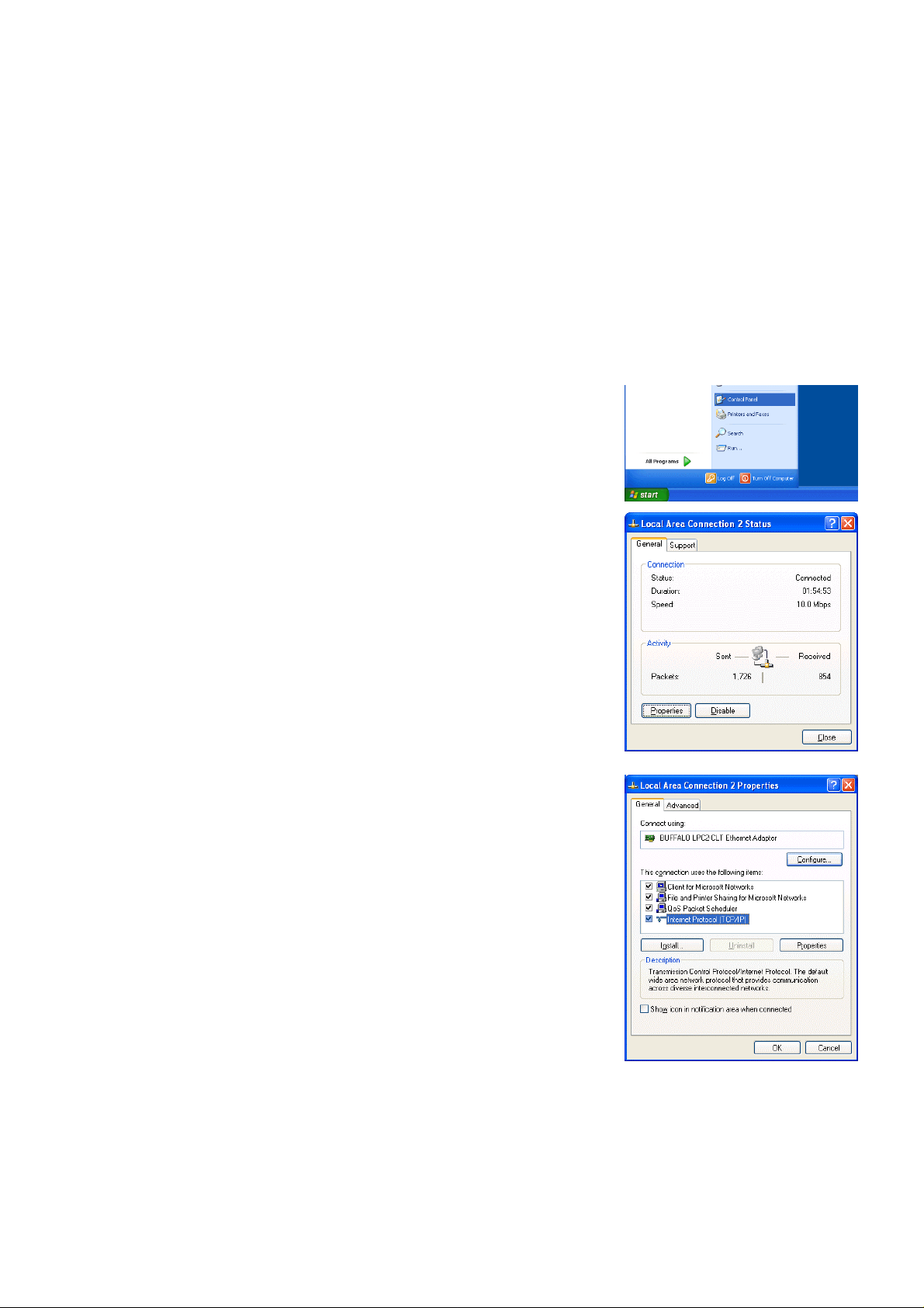
(1) Click on [Control Panel] under [Start] to open the Control Panel.
(2) In the Control Panel window, double click [Network and Dial-up
Connections] and the Netw ork and Dial-u p Connec tion s windo w will
open. Double click on [Local Area Setting] and the [Local Area
Connection Status] dialog will open. Click [Properties].
(3) In the [Local Area Connection Properties] dialog, click [Internet
Protocol] to select it and click the [Properties] button.
2
Page 4
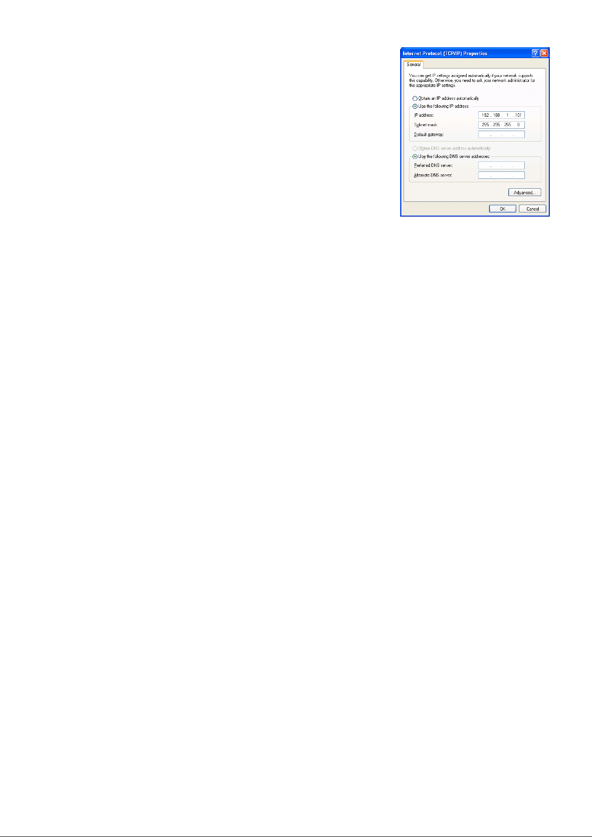
(4) In the [Internet Protocol (TCP/IP) Prop erties] dialog, click [Use the
following IP address] and enter the IP address (for example,
“192.168.1.101”) that you want to set in the IP address field.
You normally set [255.255.255.0] as the subnet mask.
Note: Ask your LAN admini stra tor to provide the IP addresses and subnet
mask.
(5) Click the [OK] button to close th is dialog, and then clos e the other
open dialogs to complete the network setting.
3
Page 5
2-2 Setting the Web Browser
Perform the necessary web browser settings to enable the web browser to connect to the G-50A.
Note: The settings and screen images used as examples in this manual are based on Internet Explorer 6.0.
2-2-1 Not connecting to the Internet
If the PC you use for monitoring air conditioners and performing operations is not going to be connected to the
Internet, use the procedure given below to set the web browser environment settings.
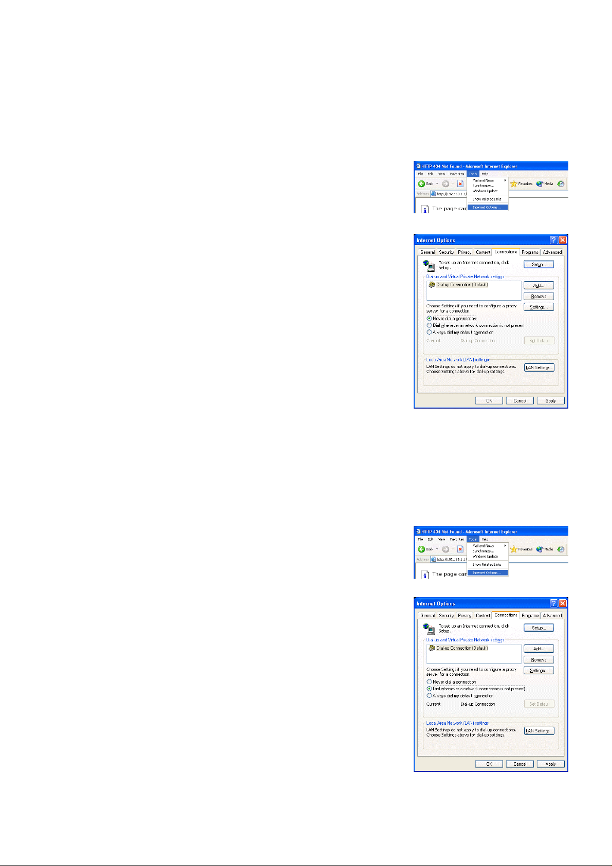
(1) Click the web browser menu item [Tools] and then click [Internet
Options…] to select that option.
(2) In the [Internet Options] tabbed dialog, click the [Connections] tab to
display that page.
(3) Select [Never dial a c onnection] in the D ial-up settings secti on and
click the [OK] button to close the dialog.
2-2-2 Connecting to the Internet using a dial-up connection
If the PC you use for m onitoring air cond ition ers and p erf orm ing operations is goi ng to con nect to t he Intern et
via a dial-up connection, use the procedure given below to set the web browser environment settings.
By performing these s ettings , a mess age will appear a sking wh ether or not to use a dial- up connec tion whe n
an Internet connect ion is necessary. In the case when you want to connect to the I nternet, connect to the
Internet by following the directions of this message.
(1) Click the web browser menu item [Tools] and then click [Internet
Options…] to select that option.
(2) In the [Internet Optio ns] tabbed dialog, click the [ Connections] tab to
display that page.
(3) Select [Dial whenever a network connection is not present] in the
Dial-up settings section and click the [OK] button to close the dialog.
4
Page 6
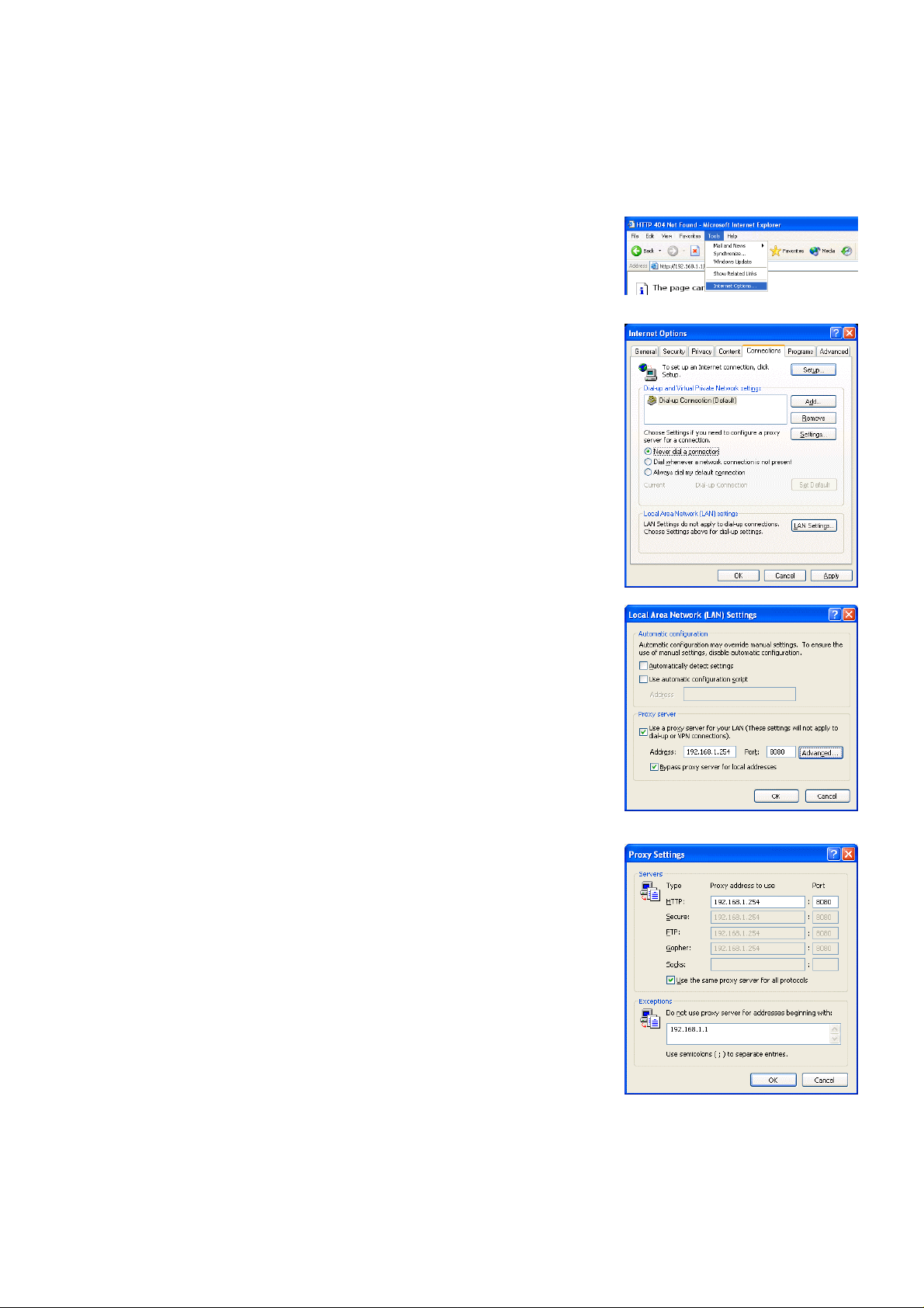
2-2-3 Connecting to the Internet using a proxy server (Using an existing LAN)
If the PC you use for monitor ing air cond itioner s and per form ing operations is go ing to acc ess the Inter net vi a
proxy server by conn ecting to an ex isting L AN such a s a LAN within your com pany, use the proce dure gi ven
below to set the web browser environment settings.
By performing these settings, your PC will connect to a proxy server only when connecting to the Internet.
(1) Click the web browser menu item [Tools] and then click [Internet
Options…] to select that option.
(2) In the [Internet Optio ns] tabbed dialog, click the [ Connections] tab to
display that page.
(3) Select [Never dial a connection] in the Dial-up setting section.
(4) Click the [LAN Settin g . . .] button in the Local Area Network (LAN)
settings section to display the Local Area Network (LAN) Settings
dialog.
(5) In the Local Are a N etwork (LAN) Settings dialog, c h eck [Bypass proxy
server for local addresses] and click the [Advanced...] button.
(6) Enter the IP address for the G-50A (e.g. 192.168.1.1) in the
Exceptions field of the Proxy Setting dialog and click the [OK] button to
close the dialog and then cl ose the other open dialogs to complete the
setting.
Note: If connecting to more than one G-50A, you can specify multiple IP addresses
like [192.168.1.1; 192.168.1.2], however, it is also possible to use the
asterisk (*) and specify [192.168.1*].
5
Page 7
3 Performing Operations
Given below is an ex planation of ho w to connect to the G -50A and how to m onitor and adjust the operation
condition of air conditioners. Follow the directions given here when performing operations.
Note: If the G-50A is restarted due to circumstances like a power interruption, wait until the screen on the G-50A main unit
displays the normal operation screen (it takes several minutes before the normal operati on screen is displayed) before
using a web browser to access the G-50A. If access is attempted while the G-50A is still starting up, the most recent data
might not be displayed or communication errors could occur.
Note: Default IP address of G-50A (GB-50A) is "192.168.1.1". (Factory setting)
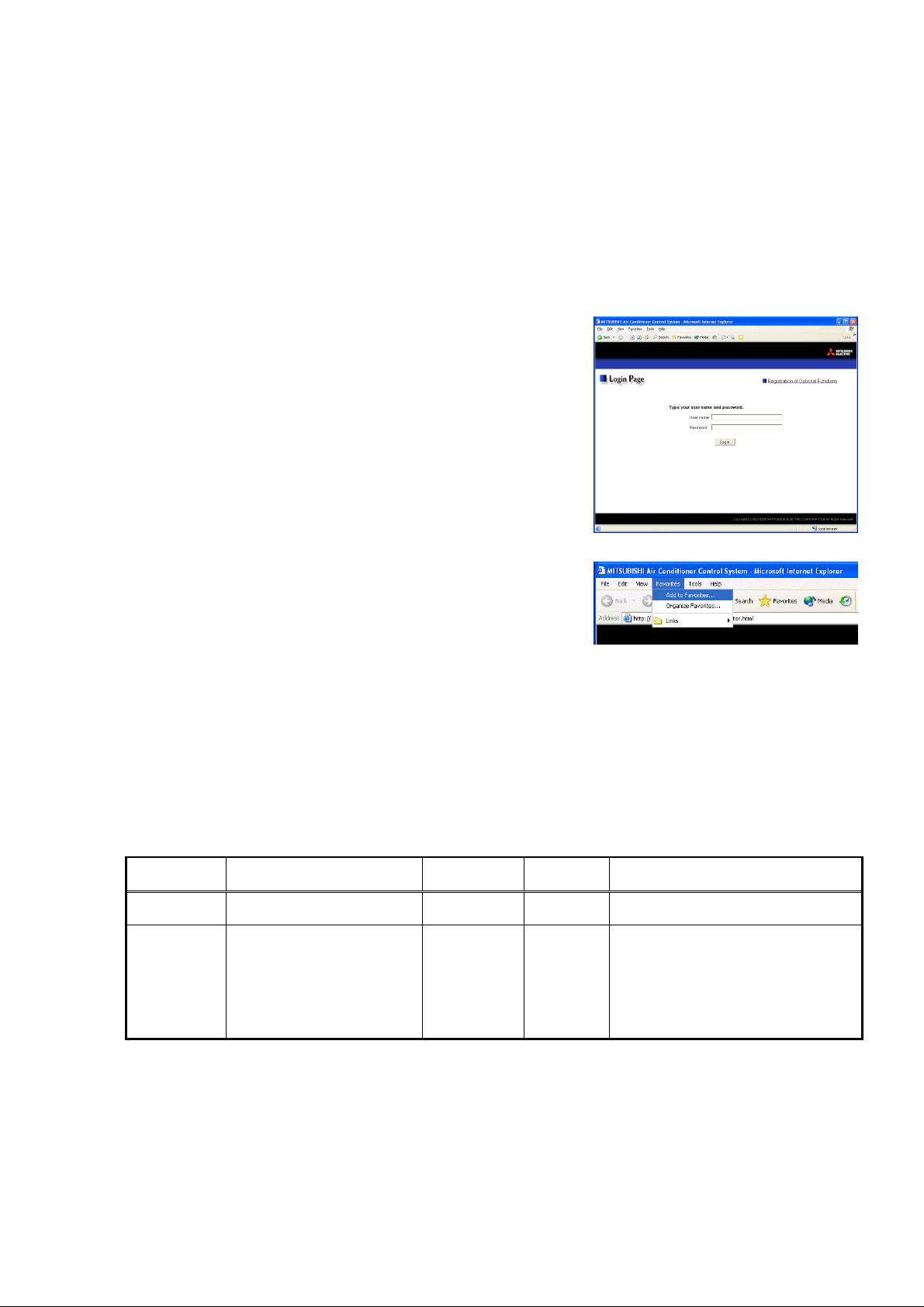
3-1 Entering the User Name and the Password, and Con necti ng to
the G-50A
(1) Enter the web page address in the address field of the web
browser as follows a nd press the [Enter] k ey on the keyboar d. A
screen appears for login.
http://[IP address of the G-50A]/administrator.html
Note: For example, type “http://192.168.1.1/administrator.html” if the G-50A IP
address is [192.168.1.1].
(2) To make it easier to co nnect the next tim e, clic k the web brows er
menu item [Favor ites] and click [Add to F avorites] to select that
option and add the address to your Favorites folder. Once this
address is added to your Favorites folder, it is not n ecessary to
input the address of (1). You can simply select it from your
Favorites folder and the G-50A page will appear.
(3) Enter the user name and the p assword in the login screen, and click the [Login] button. The screen for
monitoring the oper ation co nditio n wil l appe ar. An ex pl anation on ho w to perf orm operat ions in the norm al
operation screen begins from the next page.
The table below shows th e web page addr ess for public users and m anagers, their res pective default t he
user names and passwords, and accessible functions. If there are public users who will only operate the air
conditioners, provide them with the appropriate web page address and password.
User Web page address
Public users
Managers
Note: You can register a maximum of 50 public users and it is possible to individually specify which ai r c onditioners can be
operated by each user. (The use of this function requires a license registration.)
Note: The Web page is displayed in the same language as the computer uses and it is also possible to display the Web page in
other languages by entering the following Web page addresses.
The above addresses are for administrators. For user’s use, change [administrator.html] to [index.html].
http:// [IP address of G-50A]/
index.html
http:// [IP address of G-50A]/
administrator.html
English : HTTP://[IP address of G-50]/en/administrator.html
German : HTTP://[IP address of G-50]/de/administrator.html
French : HTTP://[IP address of G-50]/fr/administrator.html
Spanish : HTTP://[IP address of G-50]/es/administrator.html
Italian : HTTP://[IP address of G-50]/it/administrator.html
Russian : HTTP://[IP address of G-50]/ru/administrator.html
Chinese : HTTP://[IP address of G-50]/zh/administrator. htm l
Japanese : HTTP://[IP address of G-50]/ja/administrator.html
Default
user name
guest guest Monitor / operation
administrator admin
Default
password
Accessible functions
Monitor / operation
Schedule settings (Optional function)
Malfunction log monitor
Date/time adjustment
User registration
Send mail log monitor
Optional function registration
6
Page 8
3-2 Checking the Operation Condition of the Air Conditioner
“Given below is an ex pla na tion on ho w t o monitor the operation condition of a lis t of all gr ou ps , or of groups in
block units.” When a c orrect user name and password is entere d on the password entry screen, t he screen
used to monitor the operation condition of air conditioners and perform air conditioner operations will appear.
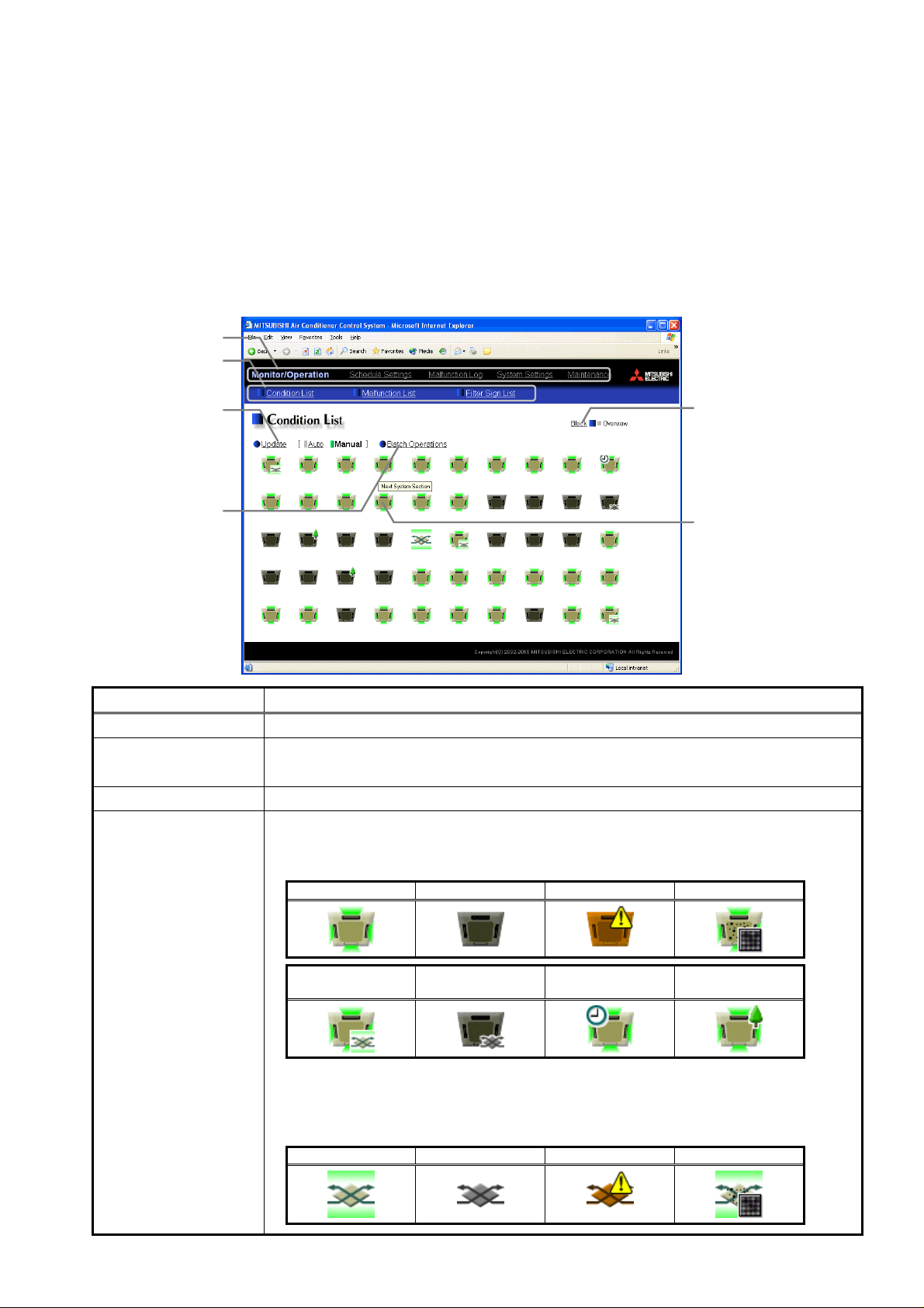
3-2-1 Checking the operation condition of all groups
Click the menu item [Monitor/Operation], or click [Condition List] in the sub menu to display a list of the
operation condition of all the air conditioner groups.
This screen allo ws the oper ator to view a list of all the groups to m onitor for air conditioner malfunc tions an d
prevent units being left on b y mistake.
Update to most recent
Click to update the screen so
that the most recent operation
Click when you want to perform
condition is shown.
Batch operation
an operation on all groups at
Block display Switches to the screen where you can check the operation condition according to block units.
Update to most recent
condition
Batch operation Click [Batch Operation] when you want to perform an operation on all groups at once.
Air conditioner icon
Menu
Sub menu
Block display
condition
Click to display the operation
condition of groups in block
Air conditioner icons
These icons are used to
once.
Item Description
Click [Update] to ensure the displayed items reflect the most recent operation condition.
When [Auto] is selected, information is updated automatically every minute to reflect the latest
information.
The operation condition is indicated by the icon that is displayed. When you point to an air
conditioner icon with the mouse cursor, the group name is displayed. To switch to the operation
screen, click on the icon. The icons used to indicate the operation condition are shown below.
(1) Air conditioner group operation condition
(2) Ventilator (Lossnay) group operation condition
ON OFF Error Filter sign
Interlocked
ventilator ON
Interlocked
ventilator OFF
Schedule set Energy saving
Note: The energy saving icon is displayed while the indoor unit group or the outdoor unit that is
connected with this group is under energy-saving control. (Before Ver.2.8, the icon is
displayed only when the indoor unit group is under control.)
ON OFF Error Filter sign
indicate the operation
condition of an air
conditioner group.
The group name is displayed
by pointing to the icon with
the mouse cursor.
Switch to the operation
screen by clicking the icon.
7
Page 9
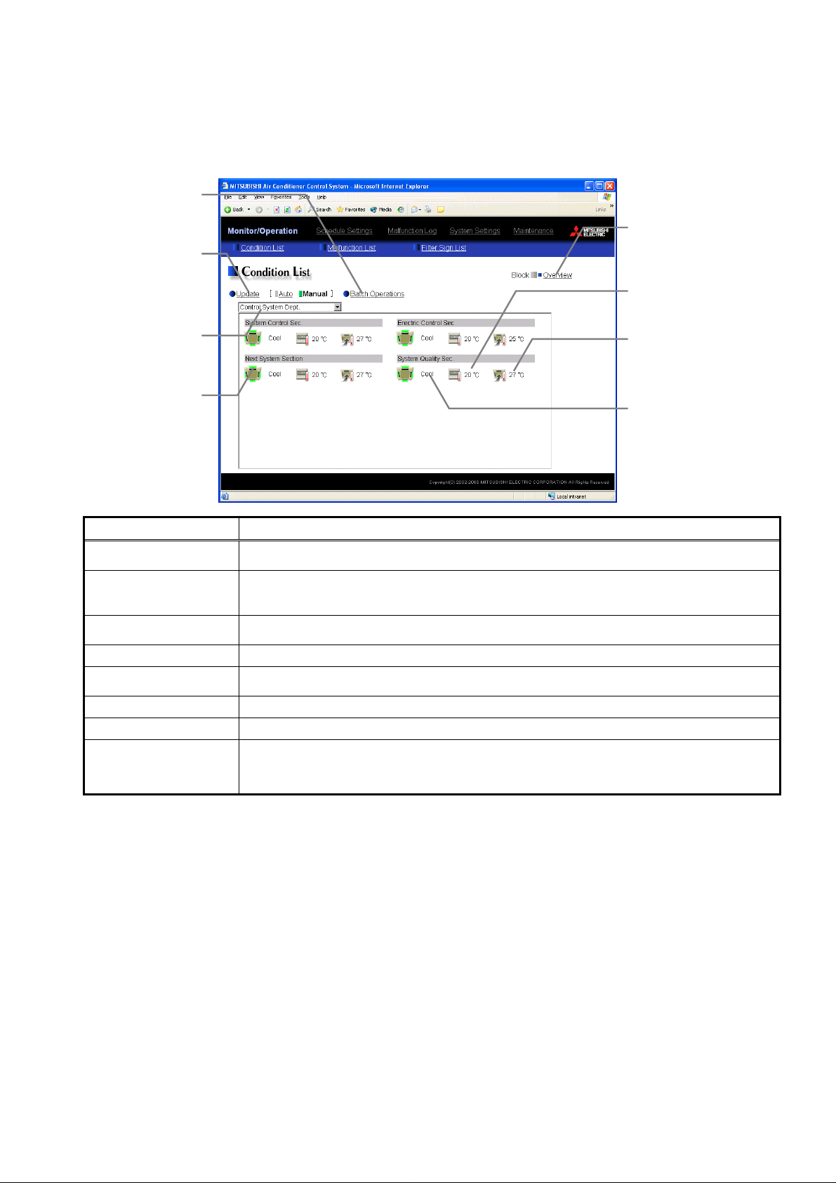
3-2-2 Checking the operation condition of groups in different blocks
t
r
Click [Block] in the s creen showing the list of al l groups to display the operatio n condition of air condit ioner
groups for each block.
Use this screen if you wan t to check data not included in the List scr een such as operation mode and set
temperature or if you want to check operation condition for each block.
Click when you want to perform
that the most recent operation
Use this to select which block to
These icons are used to indicate
the operation condition of an ai
Switch to the operation screen by
Batch operation
an operation on all groups at
Update to most recent
Click to update the screen so
condition is shown.
Select block
Air conditioner icons
once.
condition
display.
conditioner group.
clicking the icon.
Item Description
Overview display
Update to most recent
condition
Batch operation
Select block Use this to select which block to display and perform operations on.
Air conditioner icons
Operation mode display The operation mode is displayed.
Set temperature display The set temperature is displayed.
Room temperature
display
Overview display
Click to display the operation
condition of groups in a lis
of all groups.
Set tempera ture dis play
The set temperature is
displayed here.
Room temperature display
The temperature of the
indoor unit’s intake is
displayed here.
Operation mode display
Switches to the screen where y ou can c heck the operation condition of all the groups, whic h are
displayed in a list.
Click [Update] to ensure the displayed items reflect the most recent operation condition.
When [Auto] is selected, information is updated automatically every minute to reflect the latest
information.
Click [Batch Operation] when you want to perform an operation on all groups in the block at
once.
The operation condition is indicated by the icon that is displayed. To switch to the operation
screen, click on the icon.
The temperature of the indoor unit’s intake is displayed.
Note: Because the temperature displayed here is of the indoor unit’s intake, it could be different from the
actual room temperature.
Note: The temperature display can be set to display in either Celsius (°C) or Fahrenheit (°F).
The operation mode is
displayed here.
8
Page 10

3-3 Performing Air Conditioner Operations
K
Given below is an explanation of how to perform air conditioner operations that target one group, one block, or
all groups.
3-3-1 Performing air conditioner operations that target one group
When you click on an air conditioner icon or ventilat or (Lossnay) icon in the operati on condition monitoring
screen that shows the list o f all groups or the lis t of groups in the se lecte d block , the oper ation sc reen f or that
group will appear . The item s shown in this scr een are the current operation co nditions. Mo dify the items you
want to change and click [OK] to confir m the operat ion details. C lick [Cancel] to return to th e previous screen
without making any changes.
The name of the block is
Click to switch to ON or OFF.
Click to switch the operation
Click to adjust the air direction.
Click to reset the filter sign.
Click to cancel all operations.
Block name
displayed here.
ON/OFF
Operation mode
Set temperature
Click to adjust the se t
Air direction
mode.
temperature.
Filter sign
Cancel button
Item Description
ON/OFF Click [ON] or [OFF] to switch to ON or OFF.
Click [Cool], [Dry], [Fan], [Heat] or [Auto] to switch the operation mode.
If it is a ventilator group, select [Bypass], [Heat Recovery] or [Auto].
Operation mode
Set temperature
Air direction
Fan speed
Note: Some unit models do not support certain operation modes. Unsupported operat ion modes are not
displayed.
Note: For K control models, all modes are displayed, however, choose only the modes that can be
operated.
Click
For [Cool] and [Dry], the setting range is 19 ~ 30°C/67 ~ 87°F, for [Heat] it is 17 ~ 28°C/63 ~
83°F, and for [Auto] it is 19 ~ 28°C/67 ~ 83°F.
Note: The temperature setting range varies depending on the unit model.
Note: If it is a ventilator model, this item is not displayed.
Note: The temperature display can be set to display in either Celsius (°C) or Fahrenheit (°F).
Click to adjust the air direction.
Note: If it is a model that does not support air direction adjustment, this item is not displayed.
Note: If it is a model that does not support the swing feature, the swing option is not displayed.
Click
Note: If it is a model that does not support fan speed adjustment, this item is not displayed.
Note: The number of available fan speeds will be 2 settings, 3 settings or 4 settings, depending on the
number of fan speeds supported by the model.
Select the items you do n ot want the re mote controller to control. Clic k the word part of [ON/OFF],
to adjust the set temperature.
to adjust the fan speed.
Group name
The name of the group is
displayed here.
Interlocked ventilator
ON/OFF
Click to switch interlocked
ventilator ON or OFF.
Fan speed of
interlocked ventilator
Click to adjust the fan speed
of the interlocked ventilator.
Prohibit remote
controller operation
Click to select the items you do
not want the remote controller
to control.
Fan speed
Click to adjust the fan speed.
OK button
Click to confirm the operation
details. You must press the O
button for the operation to take
effect.
Prohibit remote controller
operation
Filter sign
Interlocked ventilator
ON/OFF
Fan speed of interlocked
ventilator
[Mode], [Set Temp] or [Filter Sign] and switch to prohibit
Note: For K control models, it is only possible to prohibit all items or enable all items.
Note: For K control models, there is no [Filter Sign] item.
Note: For ventilator models, there are no [Mode] item or [Set Temp] item.
Click [Reset] to specify whether to reset the filter sign. It is set to reset when a green indicator is
displayed on the left of Reset ([
Note: If filter signs are not triggered in the group, then this item is not displayed.
Click [ON] or [OFF] to switch interlocked ventilator ON or OFF.
Note: For groups that are not connected to an interlock ed ventilator, the items related to interlocked
ventilators are not displayed.
Click
to adjust the fan speed of the interlocked ventilator.
Note: For groups that are not connected to an interlock ed ventilator, the items related to interlocked
ventilators are not displayed.
Reset]).
or enable .
9
Page 11

3-3-2 Performing air conditioner operations that target one block
(1) Select the block you want to operate as an entir e block from the
operation condition monitoring screen for block lists and click
[Batch Operation]. If the bloc k that was select ed contains bot h air
conditioner groups and LOSSNAY groups, a selection screen
appears asking you to select whether to set air conditioners or
LOSSNAY. Click either “All air-conditioners in this block” or “All
LOSSNAY in this block” and the screen to set the batch operation
will appear.
If the block that was selec ted has only air conditioner groups or
only LOSSNAY groups, this selection screen will not appear.
(2) After you have made the settings on the screen for batch
operation, click [OK] and the operation settings for only the
adjusted items will be sent to all the air conditioner units contained
in the selected block. To return to the previous screen without
performing any operations, click [Cancel].
Note: When resetting the filter sign as part of a one-block batch operation, the
accumulated ON time used to trigger the filter sign will be reset in all
units belonging to the selected block, irrespective of whether or not the
filter sign was triggered. Use the reset filter sign operation in a batch
operation in a case such as when all the unit filters in the same batch
are cleaned at once.
Note: When allowing remote controller operation under K control, all prohibit
remote controller operation items must be set enable.
3-3-3 Performing air conditioner operations that target all groups
(1) Click [Batch Operation] from the operation condition monitoring
screen that displays all groups in a list. If the system contains both
air conditioner gr oups and LOSSNA Y groups, a select ion screen
appears asking you to select whether to set air conditioners or
LOSSNAY. Click either “All air-conditioners” or “All LOSSNAY”
and the screen to set the batch operation will appear.
If the system has only air conditioner groups or only LOSSNAY
groups, this selection screen will not appear.
(2) After you have made the settings on the screen for batch
operation, click [OK] and the operation settings for only the
adjusted items will be sent to all the air conditioner units.
To return to the previous screen without performing any
operations, click [Cancel].
Note: When resetting the filter sign as part of an all-groups batch operation,
the accumulated ON time used to trigger the filter sign will be reset in all
units, irrespective of whether or not the filter sign was triggered. Use the
reset filter sign operation in a batch operation in a case such as when all
the unit filters are cleaned at once.
Note: When allowing remote controller operation under K control, all prohibit
remote controller operation items must be set enable.
10
Page 12

3-4 Checking the List of Malfunctioning Units
Click the menu item [Mon it or/Operat ion] and then c lick the s ub m enu [Ma lfunc tion L ist]. A list of un its t hat ar e
currently malfunctioning appears.
Click to reset errors on all
units as one batch operation.
Update to most recent
Click to update the screen so
that the most recent operation
The name of the group is
The unit address is displayed
Update to most recent
condition
All reset Click [All Reset] when you want to reset the errors on all the malfunctioning units at once.
Number of malfunctioning
units
Group Name
Unit address The unit address is display
Error code The error code of the error that is causing the malfunction is displayed.
All reset
condition
condition is shown.
Group name
displayed here.
Unit address
here.
Item Description
Number of malfunctioning
units
The number of malfunctioning
units is displayed here.
Error code
The error code is displayed
here.
Click [Update] to ensure the displayed items reflect the most recent operation condition.
When [Auto] is selected, information is updated automatically every minute to reflect the latest
information.
The number of malfunctioning units is displayed.
The name of the group is displayed.
Note: If a unit, such as an outdoor unit or system controller, has not been registered in a group that is the
object of the operation, this area will be blank.
11
Page 13

3-5 Checking the List of Units with a Triggered Filter Sign
Click the menu item [Monitor/Operation] and click the sub m enu [Filter Sign List]. A list of the units with a
triggered filter sign appears.
Update to most recent
Click to update the screen so
that the most recent operation
condition
condition is shown.
Group name
The name of the group is
displayed here.
Unit address
The unit address is displayed
here.
Item Description
Update to most recent
condition
All reset
Number of units with
triggered filter signs
Group name The group name is displayed.
Unit address The unit address is displayed.
Reset units individually Click [Reset] when you want to reset the filter sign for the group the units belong to.
Click [Update] to ensure the displayed items reflect the most recent operation condition.
When [Auto] is selected, information is updated automatically every minute to reflect the latest
information.
Click [All Reset] when you wa nt to reset the filter sign on all units with a triggered filter sign at
once.
The number of units with currently triggered filter signs is displayed.
All reset
Number of units with
triggered filter signs
Reset units individually
Click to reset the filter sign on all
units with triggered filter signs.
The number of units with
currently triggered filter signs is
displayed here.
Click to reset the filte r sig n for
the group the units belong to.
12
Page 14

3-6 Setting Schedules
ply
s
s
When a license is r eg is tere d for [Annual schedule/W eek l y schedu le], it is p os s ible to us e t he ann ual s c hedu le
and today’s schedule as well as additional functions for the weekly schedule. If a license has not been
acquired, only the weekly schedule functions available on the G-50 unit can be used (if a license has not been
acquired, refer to the operation manual for the G-50 unit for details on using its weekly schedule functions).
Note: As the central controller GB-50A main body is not equipped with a LCD for settings, the weekly schedul e functions of the
main body are not available.
Without the registered license
Set on the main unit.
G-50A
Man-Machine Interface
Weekly schedule
(1) Frequency of operations per day
12 operations
(ON/OFF: 3 each, Prohibit/Enable: 3 each)
(2) Operation items
[1] ON/OFF
[2] Temperature setting (19-28°C/67 ~ 83°F)
[3] Prohibit/enable remote controller operation
(3) Time setting unit
10 minutes
Note: It is not possible to use the browser to
check the settings or details of the main
unit’s weekly schedule functions.
Up to 3 ON settings per day
The temperature setting must
be set together with [On]
The minimum setting unit i
10 minutes
A schedule for that day can be modified without
modifying the weekly schedule or annual schedule.
When a license is registered, it is possible to set different weekly/annual/today’s schedules for each air
conditioner group. Mor eover, for any weekly/annual/ today’s schedule run for a par ticular day, the priority in
which it is run will be from the highest and the order will be [Today’s], [Annual], [Weekly].
SUN
4
11
18
25
MON
5
12
19
26
August, 2002
WED
TUE
SUN
7
6
4
14
13
11
21
20
18
28
27
25
MON
Group 1
THU
TUE
1
8
5
15
12
22
19
29
26
August, 2002
FRI
SAT
WED
2
3
SUN
MON
9
10
7
6
16
17
4
5
14
13
23
24
11
12
21
20
31
30
18
19
28
27
25
26
Group 2
August, 2002
THU
FRI
TUE
1
8
6
15
16
13
22
23
20
29
30
27
SAT
WED
2
3
9
10
7
17
14
24
21
31
28
With the register ed license
Set on the browser.
G-50A
Weekly schedule
(1) Frequency of operations per day
12 operations
(2) Operation items
[1] ON/OFF
[2] Operation mode
[3] Temperature setting (17-30°C/63 ~ 87°F)
Note: Settable temperature range varies according to
model.
Note: The CITY MULTI model supports a temperature
setting range of 12-28°C / 53-83°F when in
Heat mode.
[4] Prohibit/enable remote controller operation
(3) Time setting unit
1 min
Annual schedule
Up to 50 days per year, such as public holidays and
summer vacation can be scheduled as days that do
not com
with the weekly schedule.
Today’s schedule
Group 3
THU
FRI
SAT
1
2
3
8
9
10
15
16
17
22
23
24
30
31
29
Up to 3 ON settings per day
The temperature setting must
be set together with [On]
The minimum setting unit i
10 minutes
Can set for public holidays
The current day’s schedule
can be modified
Days run by Weekly Schedule
Days run by Annual Schedule
Day run by Today’s Schedule
13
Page 15

3-6-1 Setting the Weekly S chedule
t
r
Click the menu item [Schedule Setti ngs] and click [Weekly Schedule] in the sub m enu to display the W eekly
Schedule setting screen. To set a weekly schedule, you first must select what will be the target of this schedule
and then set the schedule details from Sunday right through to Saturday.
Note: When the contents of an operation are executed as part of a schedule these contents will continue to be in effect until they
are changed by a schedule or browser etc. Therefore, if you are setting a sc hedul e t h at is only for a particular day, be sure
to set your schedule in a way that will not impact on the next day’s operation.
For example, if you wish to prohibit operations being performed from the remote controller after 17:00, set a Prohibit
operation for 17:00 and set an Enable operation for 23:59.
Setting Range
Select the range tha
scheduling will be set for.
Block Name
Select the block to be set.
Group Name
Select the group to be set.
Group Numbe
Select the group to be set.
Copy (Group) / Paste
Click to copy or paste a
schedule between groups.
Undo button
Click to undo the changed
(1) Select the target for the schedule being set
(1-1) Select a particular group
If you wish to set a s chedule for a particular group, se lect [Group]
from the Setting Range box.
Select the nam e of the block that the gr oup belongs to, and t hen
select the group name in the Setting Object box.
Alternatively it is possible to just select the group name and the
group number. Once the group is selected, the contents of the
schedule saved for that group will be displa yed in the Contents of
Schedule box.
Select a day of the week
Select which day to set the
schedule for.
Copy (Day of the week)
/Paste
Click to copy or paste a
schedule between each day of
the week.
Contents of Schedule
Operations set for the schedule
are displayed here.
Edit button
Click to set a schedule
operation.
Delete button
Click to delete a schedule
operation.
Save Settings button
Click to save the contents of the
schedule setting. The schedule
settings will not be saved unless
this button is pressed.
14
Page 16

(1-2) Select all groups in a block
If you want to set a sc hedule to be used b y all groups in a bl ock,
select [Block] from the Setting Range box.
Select the name of the block that the groups belong to from the
Setting Object b ox. Alternatively, if you click on a group num ber,
the block that the gr oup belongs to gets s elected (groups cannot
be selected unless they belong to a block).
If you select a block for the Object of Setting and the selected block
contains both air conditioner groups and LOSSNAY groups, a
selection screen wil l appear ask ing whether to set air conditioners
or LOSSNAY. Select [All air-conditioners in this block] or [All
LOSSNAY in this block].
If either air conditioner groups or LOSSNAY groups are not present
in the selected block, then this selection screen will not appear.
Next a screen to select the schedule setup method will appear.
Select either [New settings] or [Based on the following group
settings]. If you plan to add to an exis ting sett ing, an d then c hoose
to base it on an ex isting setting and select the nam e of the group
you want to base the setting on and click the [OK] button.
If you chose to make a new sett ing, the Contents of Schedule box
will appear complete ly blank. If you chose to base your setting on
an existing grou p, the contents of the schedule set for that gro up will appear i n the Contents of Schedule
box.
(1-3) Select all groups
When you want to set a schedule that will apply to all groups,
select [All Group] in the Setting Range box.
If you select all groups and the system contains both air conditioner
groups and LOSSNAY groups, a selection screen will appear
asking whether to se t air cond itioner grou ps or LOS SNAY groups.
Select [All air conditioners] or [All LOSSNAY]. If either air
conditioner groups or LOSSNAY groups are not present in the
system, this screen will not appear.
15
Page 17

Next a screen to select the schedule setup method will appear.
Select either [New settings] or [Based on the following group
settings]. If you plan to add to an exis ting sett ing, an d then c hoose
to base it on an ex isting setting and select the nam e of the group
you want to base the setting on and click the [OK] button.
If you chose to make a new sett ing, the Contents of Schedule box
will appear complete ly blank. If you chose to base your setting on
an existing grou p, the contents of the schedule set for that gro up will appear i n the Contents of Schedule
box.
(2) Select the day of the week
Click the day of the week listed in the Contents of Weekly
Schedule box you want to set the schedule for. You can select
from Sunday through to Saturday.
(3) Set the contents of the schedule
When one of the [Edit] bu ttons in the Contents of Schedule box is
clicked, a screen to s et a schedule oper ation will app ear. Use this
screen to set when to run an operation and set the type of schedule
operation (ON/OFF, operation mode, tem perature setting, pro hibit
remote controller operation) and then press the [OK] button.
It is also possible to set a schedule operation that is only an
operation mode or temperature setting modification. To do this,
simply limit your setting to the particular details you want to
change.
Note: The CITY MULTI model supports a temperature setting range of
12-28°C / 53-83°F when in Heat mode.
Note: When setting a schedule for all groups or for a block , it is possible to set all operation
modes such as Auto mode etc, but if some targeted air conditioner units do not have
such a function, then those units will not run in the specified mode. When setting the
schedule, consider what functions are supported by the air conditioner units.
Note: When setting a schedule for all groups or for a block, it is possible to set prohibit remote controller items individually. When
allowing remote controller operation under K control, however, all items must be set enable.
Note: When setting a schedule for ventilator units, the temperature setting is not displayed. Moreover, the prohibit remote
controller operation is simply [ON/OFF].
(4) Copy a schedule to another day of the week or to another group
OK button
Copy (Day of the week) / Paste
When copying a schedule between each day of the week, click
"Copy (Day of the week)" button. The color of the button turns t o
green (which means the button is selected). Select the desired day,
and click "Paste" button.
When copying the entire week's schedule between groups, click
"Copy (Group)" button. S elect the desire d group, and c lick "Paste"
button.
Note: The schedule of the air conditioner c annot be copied to the ventilation
equipment (LOSSNAY), and the schedule of the ventilation equipment
cannot be copied to the air conditioner.
Note: The operation mode that can be pasted and the temperature setting
range vary depending on the unit type.
Copy (Group) / Paste
(5) Save the contents of schedule
After you have fin ished setting the c ontents of the sc hedule, save
the schedule setting by clicking the [Save Settings] button.
If the contents of the schedule setting have changed since the
previous save, you can click the [Undo] button to restore the setting
contents back to the saved settings.
Note: When saving a schedule setting for all groups or for a block containing
multiple groups, it can take several minutes until the setting is complete
due to the large number of units being set.
16
Save Settings button
Page 18

3-6-2 Setting an Annual Schedule
t
r
Click the menu i tem [Schedule Settings] and c lick [Annual Sch edule] in the s ub menu to dis play the Annu al
Schedule setting scr een. You can use the an nual sc hedule t o set sched ules for days such as public holid ays
and summer vacation t hat need to be schedu led differently to the weekly schedule. For eac h air conditioner
group, it is possible to set 50 day-long settings up to 24 months into the future (including the current month).
Settings for days that have passed will be deleted automatically.
To set an annual schedu le, f irst s elect the ran ge an d o bjec t of the sched ule s ettin g and then set th e conte nts
of the schedule for each schedule pattern. After setting the c ontents of the s chedule patter n (Pattern 1 – 5),
allocate the schedule pattern you wish to use for the days such as public holidays or summer vacation you are
setting the annual schedule for.
Note: When the contents of an operation are executed as part of a schedule these contents will continue to be in effect until they
are changed by a schedule or browser etc. Therefore, if you are setting a sc hedul e t h at is only for a particular day, be sure
to set your schedule in a way that will not impact on the next day’s operation.
For example, if you wish to prohibit operations being performed from the remote controller after 17:00, set a Prohibit
operation for 17:00 and set an Enable operation for 23:59.
Setting Range
Select the range tha
scheduling will be set for.
Select the block to be set.
Select the group to be set.
Select the group to be set.
Copy (Group) / Paste
schedule between groups.
Click to undo the changed
Block Name
Group Name
Group Numbe
Click to copy or paste a
Undo button
(1) Select the target for the schedule being set
Follow the procedur e outlined for the weekl y s chedule (see 3-6-1) to select the range and object of the
schedule setting.
(2) Select the schedule pattern you want to set
In the Contents of Annual Schedul e box situa ted at th e upper r ight
part of the screen, ch oos e t he p attern you wis h t o s et from Pattern
1 - 5. (If you do not need to m odify any of the existing schedule
pattern settings, then skip steps (2) and (3).)
Select the schedule patter n
Select which pattern you wish to
set the schedule for.
Contents of Schedule
Operations set for the schedule
are displayed here.
Copy (Pattern) / Paste
Click to copy or paste a
schedule between each pattern.
Edit button
Click to set a schedule
operation.
Delete button
Click to delete a schedule
operation.
Calendar
Use the calendar to specify the
days that the selected schedule
pattern will be allocated for.
Save Settings button
Click to save the contents of the
schedule setting. The schedule
settings will not be saved unless
this button is pressed.
17
Page 19

(3) Set the contents of the schedule setting
When one of the [Edit] bu ttons in the Contents of Schedule box is
clicked, a screen to s et a schedule oper ation will app ear. Use this
screen to set when to run an operation and set the type of schedule
operation (ON/OFF, operation mode, tem perature setting, pro hibit
remote controller operation) and then press the [OK] button.
It is also possible to set a schedule operation that is only an
operation mode or temperature setting modification. To do this,
simply limit your setting to the particular details you want to
change.
Note: The CITY MULTI model supports a temperature setting range of
12-28°C / 53-83°F when in Heat mode.
Note: When setting a schedule for all groups or for a block, it is possible to set all operation modes such as Auto mode etc, but if
some targeted air conditioner units do not have such a function, then those units will not run in the specified mode. When
setting the schedule, consider what functions are supported by the air conditioner units.
Note: When setting a schedule for all groups or for a block, it is possible to set prohibit remote controller items individually. When
allowing remote controller operation under K control, however, all items must be set enable.
Note: When setting a schedule for ventilator units, the temperature setting is not displayed. Moreover, the prohibit remote
controller operation is simply [ON/OFF].
OK button
(4) Specify the day(s) for pattern allocation
Allocate the set schedu le pattern for days s uch as public holi days
or summer vacation that has scheduling requ irements different to
the weekly schedule.
To allocate a sc hedule pattern to a d ay, first click the pattern you
wish to allocat e to s elect it and then s elec t th e da y in the c ale ndar
by clicking on the rectangle corresponding to the day. When
selected, the da y will displa y the number of the pattern that has
been allocated.
If you wish to rem ove a pattern allocation f rom a day, select [ Pattern Cancel] an d then click on that day’s
rectangle.
(5) Copy a schedule to another pattern or to another group
Copy (Pattern) / Paste
When copying a schedule between each pattern, click "Copy
(Pattern)" button. The color of the button turns to green (which
means the button is s e lec te d) . S elect the desired pattern, and c lic k
"Paste" button.
When copying all pa tterns of sc hedules or an al located day of the
pattern between each group, click "Copy (Group)" button. Select
the desired group, and click "Paste" button.
Note: The schedule of the air conditi oner cannot be copied to the ventilat ion
equipment (LOSSNAY), and the schedule of the ventilation equipment
cannot be copied to the air conditioner.
Note: The operation mode that can be pasted and the temperature setting
range vary depending on the unit type.
Copy (Group) / Paste
(6) Save the contents of schedule
After you finished setting the contents of the schedule, save the
schedule setting by clicking the [Save Settings] button.
If the contents of the schedule setting have changed since the
previous save, you can click the [Undo] button to restore the setting
contents back to the saved settings.
Note: When saving a schedule setting for all groups or for a block containing
multiple groups, it c an t ake several minutes until the setting is complete
due to the large number of units being set.
Save Settings button
18
Page 20

3-6-3 Modifying Today’s Schedule
t
r
Click the menu it em [Schedule S ettings], or c lick [Toda y’s Schedule] in the sub m enu to displa y the Today’s
Schedule setting screen. Today’s Schedule can be used to set a valid schedule for just the current day without
modifying the weekly or annual schedule.
To set Today’s Schedule, first select the range and object of the setting and then set the contents of the
schedule.
Note: When the contents of an operation are executed as part of a schedule these contents will continue to be in effect until they
are changed by a schedule or browser etc. Therefore, if you are setting a sc hedul e t h at is only for a particular day, be sure
to set your schedule in a way that will not impact on the next day’s operation.
For example, if you wish to prohibit operations being performed from the remote controller after 17:00, set a Prohibit
operation for 17:00 and set an Enable operation for 23:59.
Setting Range
Select the range tha
scheduling will be set for.
Block Name
Select the block to be set.
Group Name
Select the group to be set.
Group Numbe
Select the group to be set.
Copy (Group) / Paste
Click to copy or paste a
schedule between groups.
Undo button
Click to undo the changed
(1) Select the target for the schedule being set
Follow the procedure outlined for the weekly schedule (see 3-6-1) to select the range and object of the
schedule setting.
(2) Set the contents of the schedule setting
When one of the [Edit] buttons in the Contents of Schedule box is
clicked, a screen to set a schedule operat ion will appear. Use this
screen to set when to run an op eration and set the t ype of schedule
operation (ON/OFF, operation mode, temperature setting, prohibit
remote controller operation) and then press the [OK] button.
It is also possible to set a schedule operation that is only an operation
mode or temperature setting modification. To do this, simply limit your
setting to the particular details you want to chan ge.
Note: The CITY MULTI model supports a temperature setting range of
12-28°C / 53-83°F when in Heat mode.
Note: When setting a schedule for all groups or for a block, it is possible to set
all operation modes such as Auto mode etc, but if some targeted air
conditioner units do not have such a function, then those units will not
run in the specified mode. W hen setting the schedule, consider what
functions are supported by the air conditioner units.
Note: When setting a schedule for all groups or for a block, it is possible to set prohibit remote controller items individually. When
allowing remote controller operation under K control, however, all items must be set enable.
Note: When setting a schedule for ventilator units, the temperature setting is not displayed.
Moreover, the prohibit remote controller operation is simply [ON/OFF].
Contents of Schedule
Operations set for the schedule
are displayed here.
Edit button
Click to set a schedule
operation.
Delete button
Click to delete a schedule
operation.
Save Settings button
Click to save the contents of the
schedule setting. The schedule
settings will not be saved unless
this button is pressed.
OK Button
19
Page 21

(3) Copy a schedule to another group
When copying a schedule of the day between each group, click
"Copy (Group)". The color of the button turns to green (which
means the button is selec ted). Select the des ired group, and click
"Paste" button.
Note: The schedule of the air conditioner c annot be copied to the ventilation
equipment (LOSSNAY), and the schedule of the ventilation equipment
cannot be copied to the air conditioner.
Note: The operation mode that can be pasted and the temperature setting
range vary depending on the unit type.
(4) Save the contents of schedule
After you have finished s ett ing th e c onte nts of the s chedul e, s ave t he
schedule setting by clicking the [Save Settings] button.
If the contents of the schedule setting have changed since the
previous save, you can click the [Undo ] button to restore the s etting
contents back to the saved settings.
Note: When saving a schedule setting for all groups or for a block containing
multiple groups, it can take several minutes until the setting is complete
due to the large number of units being set.
Copy (Group) / Paste
Save Settings button
20
Page 22

3-7 Checking the Malfunction Log
r
Click the menu item [Malfunction Lo g] to displa y a log of unit error s (the last 64 errors). Click the sub menu
[Communication Error] to display, the M-NET communication error log.
Unit error log
Click to display the unit erro
Click to clear the error log.
Update to most recent
Click to update the screen so
that the most recent operation
The date and time of error is
condition
condition is shown.
Occurred time
displayed here.
Unit error log Click [Unit Error] to display the unit error log.
Communication error log Click [Communication Error] to display the M-NET communication error lo
Update to most recent
condition
Clear log Click [Clear Log] to clear the error log that is being displayed.
Time Occurred The date and time of when the error occurred is displayed.
Error source address The unit address of where the error occurred is displayed.
Error detection source
address
Error code The error code of the error is displayed.
Time Recovered The date and time of the erro r recovery is displayed.
log.
Clear log
Item Description
Click [Update] to ensure the displayed items reflect the most recent condition.
When [Auto] is selected, information is updated automatically every minute to reflect the latest
information.
The unit address of where the error was detected is display
Communication error log
Click to display the
communication error log.
Error source address
The unit address of where the
error occurred is displayed here.
Error detection source
address
The unit address of where the
error was detected is displayed
here.
Error code
The error code of the error is
displayed here.
Error recovery date and
time
The date and time of the error
recovery is displayed here.
21
Page 23

3-8 Setting the Current Date and Time
Click the menu item [System Settings] and the Dat e/Time Setting s creen will app ear. Enter the curr ent date
and time and then press the [Save settings] to set it.
Summer time setting
Click to set the daylight saving
time.
Acquires the current Date and
Time from G-50A.
Refresh
Item Description
Current date/time
Save Settings Click the [Save Settings] to set the current date and time.
Refresh Acquires the current Date and Time from G-50A.
Enter the current date and time.
For the date, use the format [day - month - year].
Click and tick the "Automatically adjust clock for daylight saving changes" box to
adjust the daylight saving time automatically, and select your own country.
Note: If your own country is not in the selection bar, select "Custom Settings". Cl ick "Custom Settings"
button that will appear on the right to set the daylight saving time.
Summer time setting
Custom Setting Scre en
Current date/time
Enter the current date and time
here.
Save settings
Click to set the current date and
time.
Daylight saving
date and time
Set the daylight
saving time.
22
Page 24

3-9 Registering Users
Click the menu item [System Settings] and then click [User Registration] to display the User Registration
screen.
Please use this screen to add or modify a user name and password to login to the G-50A, and to register an air
conditioner that can be operated by a public user. If the air conditioners that can be operated ha ve been
specified, when a public user logs in, that user will only be able to vie w and operate the air condit ioners that
were specified.
Note: Manager : User who logs in from [../administrator.html].
Public User : User who logs in from [../index.html]. (Public users can only operate air conditioners. )
User information
The manager’s user name and
the air conditioners that can be
Public user information
The user names of the public
users and the air conditioners
that each user can use are
The user’s name is displayed
Click to undo any changes.
formanagers
used are displayed here.
displayed here.
User name
here.
Undo button
(1) Add or edit user information
Click an [Edit] button in the User Inform ation display to dis play the
screen for setting user information. Enter the user name and
password and se lect the a ir c onditi oners avai lable to t hat us er and
click [OK].
Note: When a public user logs in, only the air conditioners specified here will
be available to that user.
Note: Because managers can always operate all air conditioners, you cannot
select available air conditioners for the manager.
(2) Save user information
When you have completed the user information setting, click the
[Save Settings] button to save the user information.
If you want to undo the settings you have just made, click the
[Undo] button.
Note: If you make changes to user information but move to another page
without clicking the [Save Settings] button, the changes you made will
not be reflected. Always save your settings by clicking the [Save
Settings] button.
Available air conditioners
The air conditioners that can be
operated are displayed here.
When you position the cursor
over an icon, the group name is
displayed.
Edit button
Click to set the user information.
Delete button
Click to delete the user
information.
Save Settings button
Click to save the user
information.
The setting will not be saved
unless you click this button.
OK button
Save Settings button
23
Page 25

3-10 Checking the Send Mail Log
Click the menu item [Maintenance] to display the log of mail sent when an error occurred and after error
recovery. In order for a m ail to be s ent when a n error occurs , the date rel ated to s ending the m ail m ust be t o
set using Initial Setting Tool.
Click to clear the send mail log.
Update to most recent
Click to update the screen so
that the most recent condition is
The date and time when the
mail was sent is displayed here.
Update to most recent
condition
Clear log Click [Clear Log] to clear the send mail log.
Send date/time The date and time of when the error occurred is displayed.
Error source address
Error code The error code of the error is displayed.
Error status This indicates whether mail was sent when error occurred or after error recovery.
Send mail status This indicates whether the mail was successfully sent by displayi ng [OK] or [NG].
Clear log
condition
shown.
Send date/time
Item Description
Click [Update] to ensure the displayed items reflect the most recent condition.
When [Auto] is selected, information is updated automatically every minute to reflect the latest
information.
The unit address of where the error occurred is displayed.
Note: If an error occurs on general equipment, PLC number for General Equipm ent (row number 1 to 20
that PLC error mail setting is made on initial setting Web) and General Equipment number (up to 32
pieces of general equipment that are controlled by PLC for general equipment) will appear.
Error source address
The unit address of where the
error occurred is displayed here.
Error code
The error code is displayed
here.
Send mail status
This indicates whether the mail
was successfully sent by
displaying [OK] or [NG].
Error status
This indicates whether mail was
sent when error [Occurred] or
after error [recovery].
24
Page 26

4 Registering a License for Optional Functions
r
Given below is an explanation on how to register a license for optional functions. In the Login screen for
managers (see 3-1), click [Registration of Optional Functions] and the Registration of Optional Functions
screen will appear.
Please ask the dealer you purchased the pr oduct from f or more details on the o ptional functions and how to
purchase a license number.
Current Status
This indicates whether the
optional function is available fo
use.
Software version
Software version is displayed.
Registration of license
Click to register your license.
button
(1) Open the Registration of Optional Function screen
Enter the web page address in the web browser address field, click
the Enter key on the keyboard to display the Login screen (see
3-1).
Click on this screen’s menu item [Registration of Optional
Functions] to open the Registration of Optional Functions screen.
(2) Register an Optional Function
First select the optional function you wish to register from the
selection box in the Selecti ng Optional F unction secti on. When an
optional function is selected, the Current Status section will
indicate whether it is available f or use.
Next enter the license number you purchased for the optional
function in the license number entry field and click the [Registration
of license] button. Onc e this is done, the optional function will be
available for use.
If you were unsuccessf ul in registerin g an optional f unction, check that you did not enter the wrong l icense
number by mistake, that the correct optional function was selected from the selection box, and that the G-50
main unit’s date and time are set correctly.
Registration of Optional Functions
Sub menu
Click to return to the Login
Page.
Optional function
selection box
Select the optional funct ion you
want to register.
License number entry
field
Enter the license number
required for registration.
25
Page 27

HEAD OFFICE: MITSUBISHI DENKI BLDG., 2-2-3, MARUNOUCHI, CHIYODA-KU, TOKYO 100-8310, JAPAN
WT03796X08
 Loading...