

Page 1
Date: 04/00
LEVEL 2 SERVICE
GALAXY
FA9M030010
ASTRAL
GEO
GEO WAP
(DUAL BAND)
R V A: Création P. LESIGNOR 05/99 Rédigé par Verifié par Approuvé par
E R B :Modif par P. Richards 06/99
V S C :Modif SIMlatchnig 06/99
I I D :Ajout ASTRAL et GEO 07/99
S O E :Ajout Download Perso 07/08
I N F :Ajout Charg. measurements 01/00
O S G :Ajout GEO WAP 04/00
N
S
Mitsubishi Electric Telecom Europe SA Version G
ZA le Piquet, 35370 Etrelles
Phone: +33 2 99 75 71 00
Fax: +33 2 99 75 71 47
Written by Checked by Approuved by
X. GLASSON B. LEGORGEU G. LEBASTARD
Page 2

Level 2 Service Manual
GALAXY ASTRAL GEO-GEO WAP
Date: 04/00
TABLE OF CONTENTS
1 GENERAL DESCRIPTION...................................................................................................................1
2 MAIN FEATURES OF TRANSCEIVER............................................................................................... 2
2.A DESCRIPTION OF TRANSCEIVER...........................................................................................................2
2.B IMEI LABEL....................................................................................................................................... 3
2.C LABEL ART PLATE. ............................................................................................................................ 4
2.D SIM LABEL........................................................................................................................................4
2.E SIMLATCHING................................................................................................................................... 4
2.F DESCRIPTION OF OPTIONS...................................................................................................................6
3 EXPLODED DIAGRAM AND SPARE PARTS LIST........................................................................... 7
3.A EXPLODED DIAGRAM OF GALAXY.................................................................................................... 7
3.B SPARE PARTS LIST OF GALAXY ........................................................................................................ 8
3.C EXPLODED DIAGRAM OF ASTRAL ..................................................................................................... 9
3.D SPARE PARTS LIST OF ASTRAL........................................................................................................ 10
3.E EXPLODED DIAGRAM OF GEO.......................................................................................................... 11
3.F SPARE PARTS LIST OF GEO............................................................................................................... 12
4 TEST AND MEASUREMENT............................................................................................................. 13
4.A CHARGING MEASUREMENTS ............................................................................................................. 13
4.B E-GSM / DCS MEASUREMENTS........................................................................................................ 14
4.b.1 Transmitter Power and Ramp profile........................................................................................ 14
4.b.2 Phase/ Frequency/ Time relationship ....................................................................................... 14
4.b.3 Receiver Bit Error Rate (RX sensitivity).................................................................................... 14
4.b.4 Handover between E-GSM 900 and DCS 1800 stantards.......................................................... 14
4.C OPERATING INSTRUCTIONS. .............................................................................................................. 15
4.D BUZZER AND SPEAKER TESTS............................................................................................................ 16
5 DOWNLOAD OF SOFTWARE........................................................................................................... 17
5.A SOFTWARE DOWNLOAD WITH IPLTRIUM........................................................................................... 17
5.B HOW TO INSTALL IPLTRIUM SOFTWARE AND EQUIPMENT .................................................................. 17
5.C DESCRIPTION OF IPLTRIUM SOFTWARE.......................................................................................... 18
5.D START DOWNLOAD. .......................................................................................................................... 19
5.E END OF DOWNLOAD.......................................................................................................................... 20
6 DOWNLOAD OF PERSO.................................................................................................................... 21
6.A DESCRIPTION ................................................................................................................................... 21
6.B START DOWNLOAD........................................................................................................................... 22
6.C END OF DOWNLOAD.......................................................................................................................... 24
6.D HOW TO PRINT LABELS USING MS TOOLS.......................................................................................... 25
6.d.1 Equipment, Software and drivers required................................................................................ 25
6.d.2 Print labels.............................................................................................................................. 26
7 SOFTWARE VERSION....................................................................................................................... 27
8 SOFTWARE AND PERSO VERSION ................................................................................................ 27
9 OPERATOR DEBUGGING................................................................................................................. 27
10 PERSONNAL NOTES...................................................................................................................... 28
Mitsubishi Electric Telecom Europe SA Version G
ZA le Piquet, 35370 Etrelles
Phone: +33 2 99 75 71 00
Fax: +33 2 99 75 71 47
Page 3

Page 4
Level 2 Service Manual
Date: 04/00
1 General Description
GALAXY ASTRAL GEO-GEO WAP
The handportable cellular telephone described
here is designed for use in a E-GSM/DCS
network. This phone operates and complies with
the ETSI GSM phase 2 specifications.
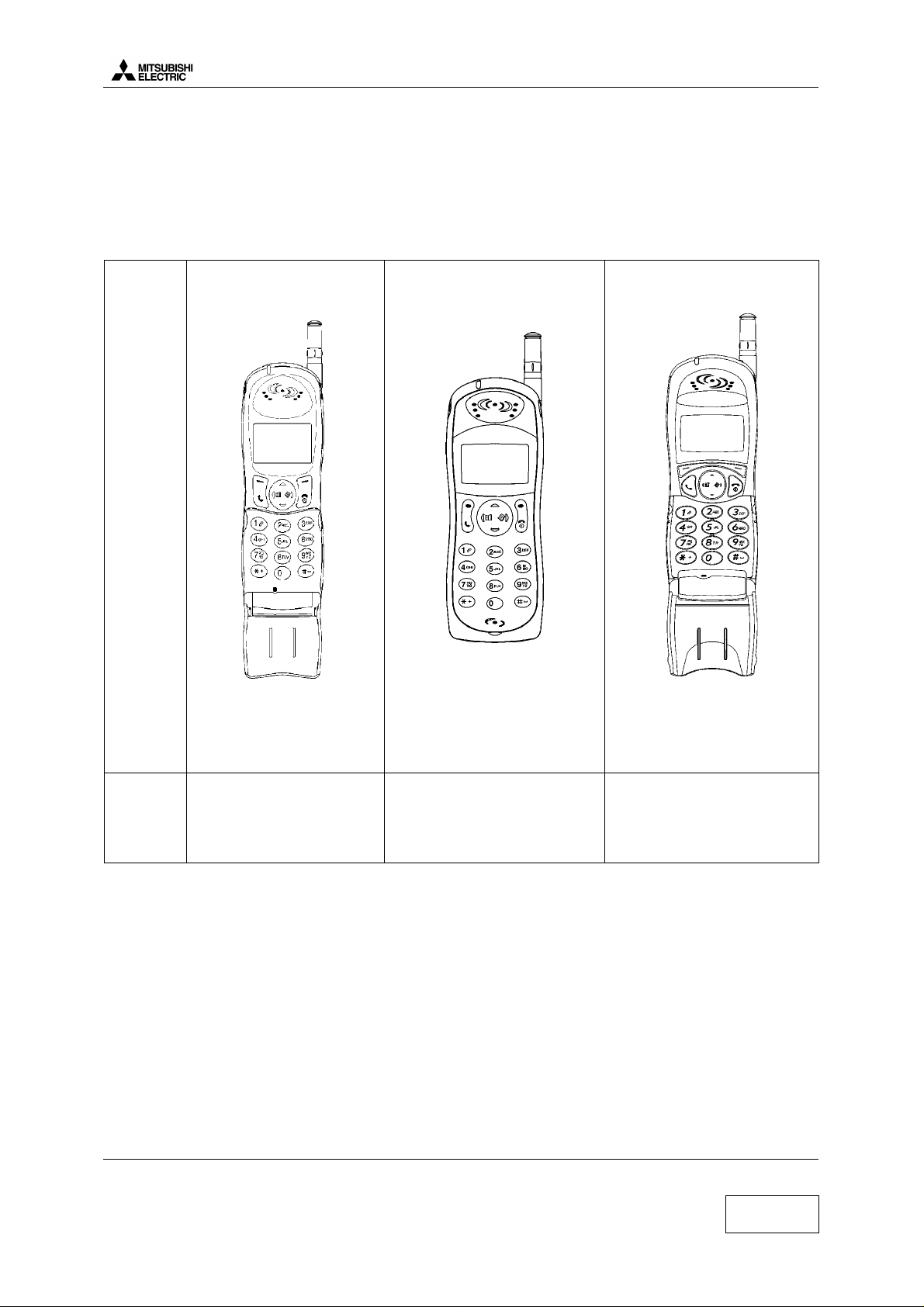
Standard kit includes following items:
MODEL
GALAXY
• Transceiver (retractable antenna type)
• Battery pack 900 mAh (NiMH type).
Reference : FZA0001A
• AC/DC Adapter for battery rapid charging
ASTRAL
GEO
Size : 135 x 48 x 27
Weight : 145 g
COLOR
Size : 135 x 48 x 27
Weight : 145 g
Dark grey
Blue mid
Wine red
Orange SU
Grey silver
Size : 135 x 48 x 26
Weight : 145 g
Bright blue
Bright green
Dark blue
Pale blue Green
Silver
Sunspice
Golden bronze
Royal blue
Speech codec :
• The mobiles M4 uses a speech codec which is able to switch from Half Rate(HR) to Full Rate(FR)
or to Enhanced Full Rate(EFR) according to network and the software and settings version.
• Enhanced Full rate (EFR) allows better voice quality at same rate as Full rate.
• Half rate (HR) is coding on 6.5 kbytes/sec (1/2 than Full rate). The network may put two customers
on one timeslot. Each customer will use this timeslot every two frames.
Main features :
• 150 hours idle time and 3 hours conversation time
• Graphic LCD
• Data fax function included
Mitsubishi Electric Telecom Europe SA Version G
ZA le Piquet, 35370 Etrelles
Phone: +33 2 99 75 71 00
Fax: +33 2 99 75 71 47
1/29
Page 5
Level 2 Service Manual
ZA le Piquet 35370 Etrelles
GALAXY ASTRAL GEO-GEO WAP
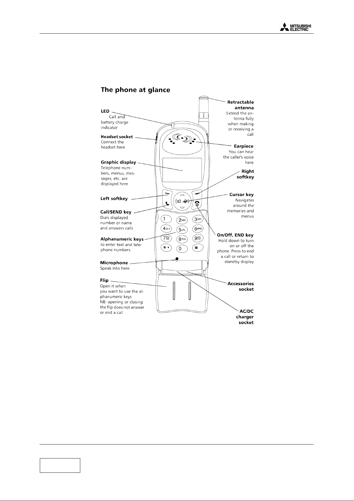
2 Main Features of Transceiver.
2.a Description of transceiver.
For M4 family, test modes will not be directly possible from the mobile . Indeed, relevant software will
be totally available on PC only. Nothing about test modes should remain inside the mobile to save
memory and software development.
Version G Mitsubishi Electric Telecom Europe SA
Date: 04/00
2/29
Phone: +33 2 99 75 71 00
Fax: + 33 2 99 75 71 47
Page 6
Level 2 Service Manual
Date: 04/00
Battery
Connector
Label ART
GALAXY ASTRAL GEO-GEO WAP
Socket 1
Cap belt clip
Socket 2
SIM Connector
SIM Label
IMEI Label
SHEET WATER
Red stripe becomes Pink
under liquid
Socket 3
Three sockets are available on the main unit :
Socket 1 : Antenna cable for RF information.
Socket 2 : Headset socket.
Socket 3 : AC/DC, CLA and accessories socket.
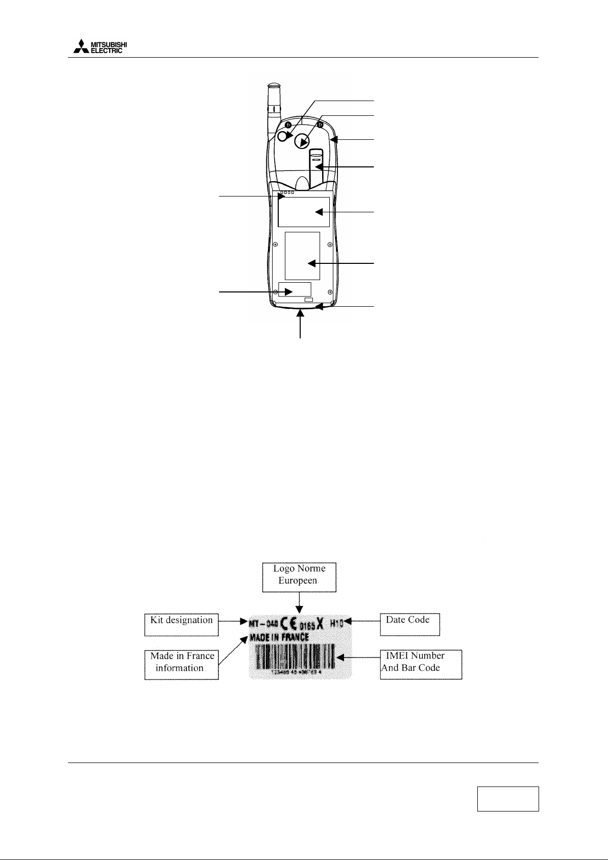
2.b IMEI label.
IMEI label stands for International Mobile Equipment Identity. The IMEI label is stuck on the rear case
of the terminal. It is held in the logic circuitry of the main board itself. If the main board is changed then
IMEI will change.
Date Code is made of 3 digits and indicates the date of shipment from factory. For example, in H09, H
stands for 1998 and 09 for September (I stands for 1999).
Mitsubishi Electric Telecom Europe SA Version G
ZA le Piquet, 35370 Etrelles
Phone: +33 2 99 75 71 00
Fax: +33 2 99 75 71 47
3/29
Page 7
Level 2 Service Manual
ZA le Piquet 35370 Etrelles
GALAXY ASTRAL GEO-GEO WAP
Bar code indicates 15 digits 123456 45 456789 4 ( for example) of the IMEI written in plain letters
above the bar code:
- 123456 : The 6 first digits indicate the Typical Approval Code. It is different according the type of
mobile.
- 45 : These 2 digits are allocated to production site.
- 456789 : The 6 last digits are a sequential number, it is different for each mobile.
- 4 : Check digit
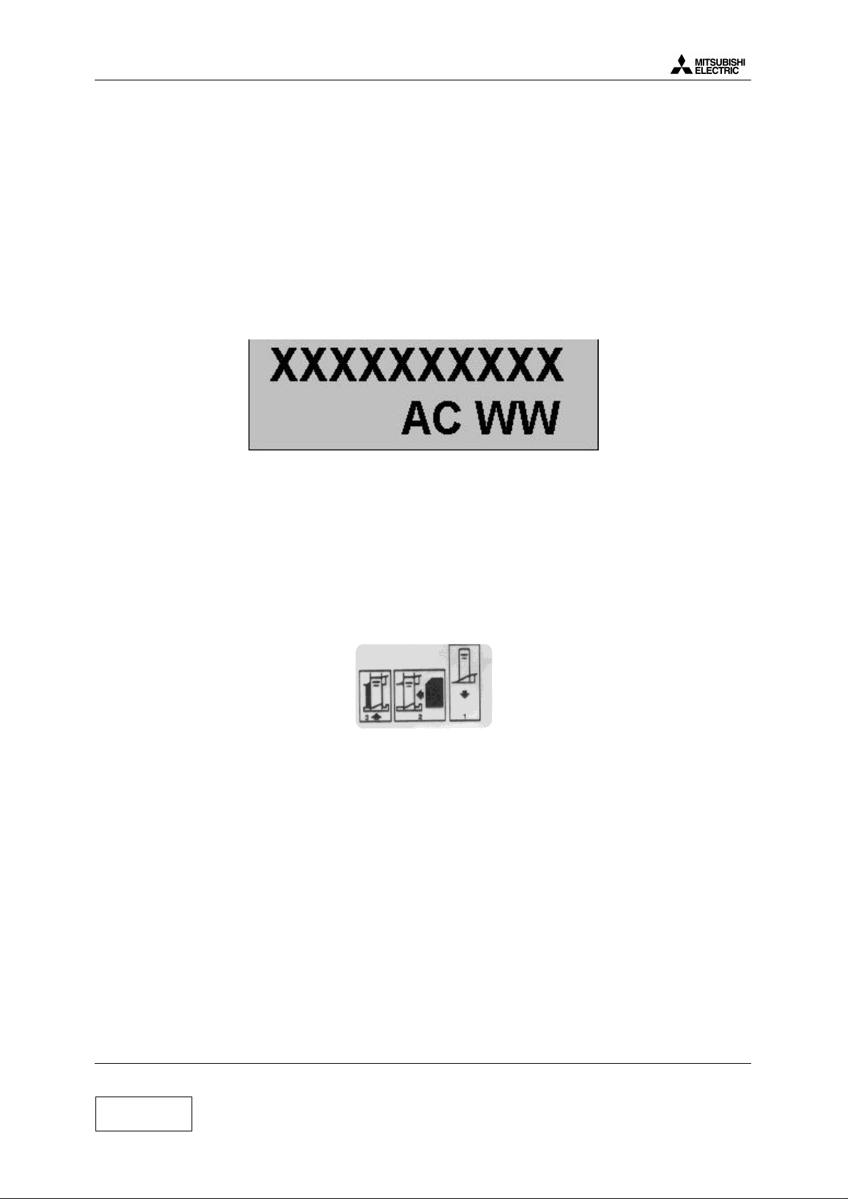
2.c Label Art Plate.
The Label Art Plate identifies the type of assembly and test the mobile has been through.
XXXXXXXXXX : 10 characters for the article code of the terminal.
A : 1 character for the assembly version of M/U.
C : 1 character for the board version.
WW : 2 characters related to production site.
2.d SIM label.
The SIM Label describes the process to follow for the SIM insertion.
1- Open the SIM card holder .
2- Insert the SIM card with the gold contact facing down and the bevelled corner of the card at the
top left.
3- Push the SIM card holder back into position.
2.e SIMLatching.
SIM Lock consists in restricting the use of the terminal to a family of SIM cards. For the SIM Lock,
three principal informations are used. These informations are read from data fields in the SIM card.
1°) IMSI (International Mobile Subscriber Identity), 15 Digits :
Example of IMSI : 208 01 55 12312312
208 = MCC = Mobile Country Code (ex : 208 for France)
01 = MNC = Network Country Code (ex : 01 for FT)
55 = NS = Network Subset
Version G Mitsubishi Electric Telecom Europe SA
Date: 04/00
4/29
Phone: +33 2 99 75 71 00
Fax: + 33 2 99 75 71 47
Page 8
Level 2 Service Manual
GALAXY ASTRAL GEO-GEO WAP
Date: 04/00
12312312 = Indifferent serial number
2°) Group IDentifier 1 (GID1):
This data field can contain digits or letters which identify a family of SIM
Ex : XX for a type for of prepaid SIM card of Service provider Y
3°) Group IDentifier 2 (GID2) :
same as GID1 to identify a sub family of SIM.
Then, from this information, we have 5 types of latch :
1°) Network Level :
latch on MCC MNC of IMSI of the SIM only
(ex : only the cards 208 01 be able to operate the mobile.
Mitsubishi use to call this latch NCK (NCK stands for “ Network Control Keys” and is the password to
lock the mobile at the network level)
2°) Network Subset Level :
Latch on MCC, MNC and digit 6 and 7 of the IMSI
Ex : latch on 208 01 55, only the SIM cards with an IMSI starting with 208 01 55 will operate the
mobile.
Mitsubishi use to call this latch NSCK (“Network Subset Control Key)
3°) Service provider level :
latch on Network (value of MCC MNC) and value of GID1 data field.
Ex : latch on the value “XX” in GID1 and MCC MNC=208 01, only the SIM cards of service provider Y
with XX stored in data field GID1 will operate the mobile.
Mitsubishi use to call this latch SPCK (Service Provider Control Key)
4°) Corporate Provider Level :
latch on network (value of MCC and MNC) and a value stored in GID2
Mitsubishi use to call this latch CPCK (Corporate Provider Control Key)
5°) IMSI level
latch on the complete IMSI of one SIM card.
Only one SIM card corresponding to the correct IMSI operates the mobile. Usually, this latch is done in
an automatic way (the first SIM card inserted in the mobile is the only SIM which can be used by this
mobile).
General information :
To lock /unlock a mobile, you need 8 digits password for each level concerned, and each mobile (one
set of passwords for one IMEI). These passwords are calculated with a special algorithm. You have
only 10 attempts to unlock correctly a mobile. After 10 unsuccessful attempt, the mobile is
permanently blocked.
To enter the unlock procedure, you need to access special menus with specific access codes.
Mitsubishi Electric Telecom Europe SA Version G
ZA le Piquet, 35370 Etrelles
Phone: +33 2 99 75 71 00
Fax: +33 2 99 75 71 47
5/29
Page 9
Level 2 Service Manual
ZA le Piquet 35370 Etrelles
GALAXY ASTRAL GEO-GEO WAP
2.f Description of options.
Model Designation
Galaxy M/U BLUE MID WT KW Blue Midnight Trium White
Galaxy M/U BLUE MID WM KB Blue Midnight Mitsubishi Black
Galaxy M/U BLUE MID WT KB Blue Midnight Trium Black
Galaxy M/U GREY SIL WT KW Grey Silver Trium White
Galaxy M/U GREY SIL WT KB Grey Silver Trium White
Galaxy M/U ORANGE SU WT KW Orange Trium White
Galaxy M/U ORANGE SU WT KB Orange Trium Black
Galaxy M/U DARK GRE WT KW Dark Grey Trium White
Galaxy M/U DARK GRE WT KB Dark Grey Trium Black
Galaxy M/U WINE RED WT KC Wine Red Trium Cassis
Galaxy M/U GREY SIL WT KB Grey Silver Trium Black
Astral M/U DARK GRE FP PBLGR WT KW Pale Blue Green Trium White
Astral M/U DARK GRE FP BRBL WT KW Bright Blue Trium White
Astral M/U DARK GRE FP BRGR WT KW Bright Green Trium White
Astral M/U DARK GRE FP DABL WTV KB Dark Blue Trium / Vodafone Black
Astral M/U DARK GRE FP DABL WTD KB Dark Blue Trium / D2 White
Astral M/U DARK GRE FP BRBL WTA KW Bright Blue Trium / Movistar White
Astral M/U DARK GRE FP DABL WT KW Dark Blue Trium White
Astral M/U DARK GRE FP DABL WTO KW Dark Blue Trium / One White
Astral M/U DARK GRE FP SILV WTI KW Silver Trium / Viag Interkom White
Astral M/U DARK GRE FP BRGR WTA KW Bright Green Trium / Movistar White
Astral M/U DARK GRE FP BRGR WTO KW Bright Green Trium / One White
Astral M/U DARK GRE FP PBLGR WTA KW Pale Blue Green Trium / Movistar White
Astral M/U DARK GRE FP DABL WTA KW Dark Blue Trium / Movistar White
Astral M/U DARK GRE FP BRBL WTO KW Bright Blue Trium / One White
Astral M/U DARK GRE FP RED WTD KB Red Trium / D2 Black
Astral M/U DARK GRE FP SIL WT KB Silver Trium Black
Astral M/U DARK GRE FP RED WTD KW Red Trium / D2 White
Astral M/U DARK GRE FP SILV WT KW Silver Trium White
Astral M/U DARK GRE FP RED WTC KB Red Trium / Coca Cola (Wind) Black
Geo M/U SUNSPICE WT KS Orange Sunspice Trium Silver RTC, Alarm, Vib
Geo M/U GOLD BRO WT KS Golden Bronze Trium Silver RTC, Alarm, Vib
Geo M/U GOLD BRO WT KH Golden Bronze Trium Hebrew RTC, Alarm, Vib
Geo M/U ROYA BLU WT KS Royal Blue Trium Silver RTC, Alarm, Vib
Geo M/U ROYA BLU WT KH Royal Blue Trium Hebrew RTC, Alarm, Vib
Geo Wap M/U GW OLIVE GR WT KS Olive Green Trium Silver RTC, Alarm, Vib, Wap
Geo Wap M/U GW DARK GRE GR WT KS Dark Grey Trium Silver RTC, Alarm, Vib, Wap
Geo Wap M/U GW DARK RED GR WT KS Dark Grey Trium Silver RTC, Alarm, Vib, Wap
Geo Wap M/U GW OR SUNSP GR WT KS Orange Sunspice Trium Silver RTC, Alarm, Vib, Wap
Geo Wap M/U GW BLUE MID GR WT KS Blue Midnight Trium Silver RTC, Alarm, Vib, Wap
Geo Wap M/U GW ROYA BLU GR WT KS Blue Midnight Trium Silver RTC, Alarm, Vib, Wap
Colour
(cover/front panel)
Logo Keypad Options
Version G Mitsubishi Electric Telecom Europe SA
Date: 04/00
Phone: +33 2 99 75 71 00
6/29
Fax: + 33 2 99 75 71 47
Page 10
Level 2 Service Manual
Date: 04/00
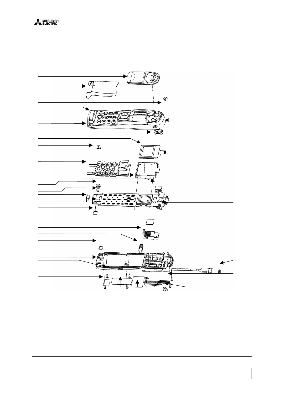
3 Exploded Diagram and Spare parts list.
222318
19
3.a Exploded Diagram of GALAXY
1
2
3
31
30
5
6
27
7
GALAXY ASTRAL GEO-GEO WAP
4
8
14
26
9
16
10 32
25
12
13
24
11
20 15
17
22
Mitsubishi Electric Telecom Europe SA Version G
ZA le Piquet, 35370 Etrelles
Phone: +33 2 99 75 71 00
Fax: +33 2 99 75 71 47
7/29
Page 11

Level 2 Service Manual
ZA le Piquet 35370 Etrelles
GALAXY ASTRAL GEO-GEO WAP
3.b Spare Parts list of GALAXY
Position Designation
1 WINDOW ASSY MD LOGO MITSUBISHI
1 WINDOW ASSY MD LOGO TRIUM
2 FLIP MONDIAL CLEAR GREY (25527)
2 FLIP MONDIAL CLEAR GREY BEN
2 FLIP MONDIAL DARK BLUE (95511)
2 FLIP MONDIAL DARK BLUE BEN
2 FLIP MONDIAL DARK BLUE MOVISTAR
2 FLIP MONDIAL DARK BLUE ONE
2 FLIP MONDIAL DARK BLUE WIND
2 FLIP MONDIAL DARK GREY (25506)
2 FLIP MONDIAL GREY WIND
2 FLIP MONDIAL ORANGE (45502 ?)
2 FLIP MONDIAL ORANGE BEN
2 FLIP MONDIAL RED WIND
2 FLIP MONDIAL WINE RED (55503)
3 CAP H/S
4 COVER ASSY MONDIAL CLEAR GREY (25527)
4 COVER ASSY MONDIAL DARK BLUE (95511)
4 COVER ASSY MONDIAL GREY (25506)
4 COVER ASSY MONDIAL ORANGE (45502 ?)
4 COVER ASSY MONDIAL RED (55503)
5 RECEIVER
6 LCD
7 KEY RUBBER BLACK MD
7 KEY RUBBER WHITE MD
7 KEY RUBBER CASSIS
8 HOLDER ASSEMBLY
9 MICRO
10 PWB ASSEMBLY
11 CASE ASSEMBLY
12 SIM CONNECTOR
13 BATTERY CONNECTOR
14 CUSHION BUZZER
15 ANTENNA
16 CAP I/O
17 SLIDER
18 CAP BELT CLIP
19 CAP RF
20 SCREW
21 LABEL IMEI
22 LABEL ART
23 LABEL SIM
24 WINDOW WATER
25 SHEET WATER
26 HOLDER MIC
27 CUSHION MIC
30 HINGE RIGHT
31 HINGE LEFT
32 BUZZER TESTE
Without SPACER LCD
Spare parts references available in the spare parts catalogue customer.
Connectors and Shields of GALAXY
Position Designation Reference
J103 CONNECTOR IO&DC 6T87934010
J201 CONNECTOR LCD M4 6T89858010
J300 JACK HEADSET 6T91950310
J400 CONNECTOR RF M4 M4FSJ00020
J600 M4-TER-ANT FS2D002810
S500 (HPA) COVER SHIELD MD-41 FS2D006110
S600 (RFIC) COVER SHIELD MD-42 FS2D006210
S100 (ONE C) COVER SHIELD MD-43 FS2D006310
Version G Mitsubishi Electric Telecom Europe SA
Date: 04/00
Phone: +33 2 99 75 71 00
8/29
Fax: + 33 2 99 75 71 47
Page 12

Level 2 Service Manual
GALAXY ASTRAL GEO-GEO WAP
Date: 04/00
3.c Exploded Diagram of ASTRAL
1
2
3
26
4
5
7
6
8
9
10 32
12
13
14
15
16
17 18
19
25 22
24 23 21 20
Mitsubishi Electric Telecom Europe SA Version G
ZA le Piquet, 35370 Etrelles
Phone: +33 2 99 75 71 00
Fax: +33 2 99 75 71 47
9/29
Page 13

Level 2 Service Manual
ZA le Piquet 35370 Etrelles
GALAXY ASTRAL GEO-GEO WAP
3.d Spare Parts list of ASTRAL
Position Designation
1 FRONT PANEL ASSY
1 FRONT PANEL ASSY NF AQUA BLUE WT
1 FRONT PANEL ASSY NF AQUA BLUE WTA
1 FRONT PANEL ASSY NF BRIGHT GREEN WT
1 FRONT PANEL ASSY NF BRIGHT GREEN WT0
1 FRONT PANEL ASSY NF BRIGHT GREEN WTA
1 FRONT PANEL ASSY NF BRIGHT GREEN WTI
1 FRONT PANEL ASSY NF DEEP BLUE WT
1 FRONT PANEL ASSY NF DEEP BLUE WT0
1 FRONT PANEL ASSY NF DEEP BLUE WTD
1 FRONT PANEL ASSY NF DEEP BLUE WTV
1 FRONT PANEL ASSY NF PALE BLUE GREEN WT
1 FRONT PANEL ASSY NF PALE BLUE GREEN WTA
1 FRONT PANEL ASSY NF PALEBLUEGREEN WTV
1 FRONT PANEL ASSY NF SILVER WTI
2 CAP H/S
3 COVER ASSY NF
4 RECEIVER
5 LCD
6 HOLDER ASSEMBLY
7 KEY RUBBER WHITE
7 KEY RUBBER BLACK
8 CUSHION BUZZER
9 HOLDER MIC
10 MICRO
11 PWB ASSEMBLY
12 CAP I/O
13 SHEET WATER
14 SIM CONNECTOR
15 BATTERY CONNECTOR
16 WINDOW WATER
17 CASE ASSEMBLY
18 ANTENNA
19 SCREW
20 CAP RF
21 CAP BELT CLIP
22 SLIDER
23 LABEL SIM
24 LABEL IMEI
25 LABEL ART
26 CUSHION MIC
32 BUZZER TESTE
Spare parts references available in the spare parts catalogue customer.
Connectors and shields of ASTRAL : Same as GALAXY
Version G Mitsubishi Electric Telecom Europe SA
Date: 04/00
10/29
Phone: +33 2 99 75 71 00
Fax: + 33 2 99 75 71 47
Page 14

Level 2 Service Manual
GALAXY ASTRAL GEO-GEO WAP
Date: 04/00
3.e Exploded Diagram of GEO
2 1
3
31
4
30
29 5
7
6
8
26
9 14
16 10
25 32
12 27
28
24
13
11
15
20
22
21 23 19 18
Mitsubishi Electric Telecom Europe SA Version G
ZA le Piquet, 35370 Etrelles
Phone: +33 2 99 75 71 00
Fax: +33 2 99 75 71 47
11/29
Page 15

Level 2 Service Manual
ZA le Piquet 35370 Etrelles
GALAXY ASTRAL GEO-GEO WAP
3.f Spare Parts list of GEO
Position Designation
1 WINDOW ASSY MB LOGO MITSUBISHI
1 WINDOW ASSY MB LOGO TRIUM
2 FLIP MOBILIA ROYAL BLUE (GEO WAP)
2 FLIP MOBILIA BLUE TCE (GEO STANDARD)
2 FLIP MOBILIA SUNSPICE (GEO STANDARD)
2 FLIP MOBILIA GOLDEN BRONZE (GEO STANDARD)
2 FLIP MOBILIA OLIVE GREEN (GEO WAP)
2 FLIP GW BLUE MIDNIGHT
2 FLIP GW DARK GREY (GEO WAP)
2 FLIP GW WINE RED (GEO WAP)
2 FLIP GW OLIVE GREEN (GEO WAP)
3 CAP H/S
4 COVER ASSY ROYAL BLUE TCE (GEO STANDARD)
4 COVER ASSY MB ROYAL BLUE (GEO WAP)
4 COVER ASSY MB SUNSPICE VPAA2239 (GEO STANDARD)
4 COVER ASSY MB GOLDEN BRONZE VPAA2238 (GEO STANDARD)
4 COVER ASSY MB OLIVE GREEN (GEO WAP)
4 COVER ASSY MB DARK GREY (GEO WAP)
5 RECEIVER
6 LCD (96 X 48)
6 LCD (115 X 65 : WAP)
7 KEY RUBBER ASSY MB SILVER
7 KEY RUBBER ASSY MB SILVER HEBREU
8 HOLDER ASSEMBLY
9 MICRO
10 PWB ASSEMBLY
11 CASE ASSEMBLY
12 SIM CONNECTOR
13 BATTERY CONNECTOR
14 CUSHION BUZZER
15 ANTENNA
16 CAP I/O
17 SLIDER
18 CAP BELT CLIP
19 CAP RF
20 SCREW
21 LABEL IMEI
22 LABEL ART
23 LABEL SIM
24 WINDOW WATER
25 SHEET WATER
26 HOLDER MIC
27 VIBRATOR MOTOR ASSY
28 VIBRATOR CUSHION
29 CUSHION MIC
30 HINGE RIGHT
31 HINGE LEFT
32 BUZZER TESTE
Spare parts references available in the spare parts catalogue customer.
Connectors and Shields of GEO : same as GALAXY and ASTRAL
Version G Mitsubishi Electric Telecom Europe SA
Date: 04/00
12/29
Phone: +33 2 99 75 71 00
Fax: + 33 2 99 75 71 47
Page 16

Level 2 Service Manual
GALAXY ASTRAL GEO-GEO WAP
Date: 04/00
4 Test and Measurement
4.a Charging measurements
To check the charging, we use a modified AC/DC and an ampermeter connected as follow :
When you plug the charger into the wall socket, the charging current is displayed by ampermeter
The charging indicator scroll on the LCD and the red top led lights up.
During pre-charge, the value of the curent is 120mA (measurment without backlight)
During rapid charge, the value of the current is 490mA (measurment without backlight)
For more details about charging, see the LEVEL 3 SERVICE MANUAL FA9M030110 at page 6.
Mitsubishi Electric Telecom Europe SA Version G
ZA le Piquet, 35370 Etrelles
Phone: +33 2 99 75 71 00
Fax: +33 2 99 75 71 47
13/29
Page 17

Level 2 Service Manual
ZA le Piquet 35370 Etrelles
GALAXY ASTRAL GEO-GEO WAP
4.b E-GSM / DCS measurements
4.b.1 Transmitter Power and Ramp profile
These two are interrelated, since the power ramp shape and its final peak value are stored in
EEPROM as adjustment values.
The peak power output must lie within 3 dB of specification and be flat to within 0.5dB over the active
period. The ramp profile is designed to give minimum harmonics, and hence it is important to ensure it
is adhered to.
Power ramp profile must be checked on all frequencies (in practice channels 975, 37 and 124 for the
900 MHz band and channels 512, 698 and 885 for the 1800 MHz band). In conclusion, the ramp must
fit the mask at all frequencies and all power levels. The mask is usually stored in the
radiocommunication tester. The test will also be available to cover the frequency and power range
automatically.
4.b.2 Phase/ Frequency/ Time relationship
This is a test of the quality of the modulation including the IQ balance and the Gaussian filters. The
phase of the carrier changes according to the arrival of 1s and 0s. Phase error must not be more than
20° peak or 5° RMS.
4.b.3 Receiver Bit Error Rate (RX sensitivity)
The specification is a Bit Error Rate (BER) of better than 2.44% for an input signal : -102 dBm for the
E-GSM 900 band, and -100dBm for the DCS 1800 band. There should be no error for -90 dBm to
-20 dBm input signal. The maximum workable error rate is 13%.
It is important that BER and RX sensitivity are good since measures of RXLEV (from -103 to -41 dBm)
and RXQUAL (from 0 to 10%) are reported back to the base station on the SACCH to assist in
handovers and power level control. Errors in reporting will lead to sub optimum use of channel space,
or interference to others.
4.b.4 Handover between E-GSM 900 and DCS 1800 stantards.
The M4 dual band may handover from the E-GSM 900 band to the DCS 1800 band automatically. If
the subscrided network has frequencies in both bands, the M4 dual band will work either in 900 MHz
or 1800 MHz band depending on the avaibility of frequencies.
Version G Mitsubishi Electric Telecom Europe SA
Date: 04/00
14/29
Phone: +33 2 99 75 71 00
Fax: + 33 2 99 75 71 47
Page 18

Level 2 Service Manual
Date: 04/00
4.c Operating instructions.
RADIOCOMMUNICATION TESTER
GALAXY ASTRAL GEO-GEO WAP
Mobile with full
battery
RF Cable NN 50 OHMS 0.8
(FT7Y005610)
NSMA ADAPTATOR FEMALE
(FT7Y010010)
M4 RF CABLE SMA L500
(FT7Y006110)
1. Insert Test SIM card in mobile
2. Connect a charged battery
3. Make a call with RADIOCOMMUNICATION TESTER and check following parameters or use the
autotest (CMD55 or CMD55 under MTS or Wavetek 4107)
E-GSM 900
PCL
5 33 +/-2dB
6 31 +/-3dB
7 29 +/-3dB
8 27 +/-3dB
9 25 +/-3dB
10 23 +/-3dB
11 21 +/-3dB
12 19 +/-3dB
13 17 +/-3dB
14 15 +/-3dB
15 13 +/-3dB
16 11 +/-5dB
17 9 +/-5dB
18 7 +/-5dB
19 5 +/-5dB
Power Level
(dBm)
tolerance
DCS 1800
PCL
Power level
(dBm)
0 30 +/-2dB
1 28 +/-3dB
2 26 +/-3dB
3 24 +/-3dB
4 22 +/-3dB
5 20 +/-3dB
6 18 +/-3dB
7 16 +/-3dB
8 14 +/-3dB
9 12 +/-4dB
10 10 +/-4dB
11 8 +/-4dB
12 6 +/-4dB
13 4 +/-4dB
14 2 +/-5dB
15 0 +/-5dB
tolerance
Mitsubishi Electric Telecom Europe SA Version G
ZA le Piquet, 35370 Etrelles
Phone: +33 2 99 75 71 00
Fax: +33 2 99 75 71 47
15/29
Page 19

Level 2 Service Manual
ZA le Piquet 35370 Etrelles
+4
+1-6-1
-30
-70
(dB)
Level
8µS
10µS
8µS
10µS
542.8µS
147 « useful » bits
GALAXY ASTRAL GEO-GEO WAP
Power ramping: Check the burst fit the mask below
RX levels : Check the values for different signal strengths
RX LEVEL RSSI (dBm)
0 Less than -110 dBm
1 -110 to -109
2 -109 to -108
27 -84 to -83
50 -61 to -60
62 -49 to -48
63 Better than -48
Bit error : Check the value for differents type
Check the Reception Bit Error Rates (RBER) and Frame Error Rates on channels 1,62 and 124 at
–102dBm for GSM band and on channels 512, 698 and 885 for the DCS band according the following
specifications :
Bit error type Value
RBER Class Ib < 0.41 %
RBER Class II < 2.44 %
FER < 0.12%
4.d Buzzer and Speaker tests
Insert a test SIM in mobile set with battery.
The volume levels of the ring tone, key tones and incoming audio can be individually adjusted in the
setting menu.
• Press MENU ,select settings, select Tones, select Volume, select ring and scroll to the item to
be adjust, Master volume, ring volume, Ramping, keys volume or speech volume.
• Select ring volume and use and keys to decrease or increase the volume of buzzer.
• Select speech volume and use and keys to decrease or increase the volume of speaker.
Version G Mitsubishi Electric Telecom Europe SA
Date: 04/00
16/29
Phone: +33 2 99 75 71 00
Fax: + 33 2 99 75 71 47
Page 20

Level 2 Service Manual
GALAXY ASTRAL GEO-GEO WAP
Date: 04/00
5 Download of software
The software in the mobile consists of two files downloaded independantly.
The corp of this software is downloaded using IPLTrium.
The settings file (ringing, customization…) is downloaded with MS Tools. MS tools also allows to enter
test mode in order to reset user data (security code) , to print labels (imei & factory name plate), to
reset the permantly blocked indicator providing you have the access rights.
5.a Software download with IPLTrium
This part describes how to use the IPLTRIUM software.
To download a software file, you need IPLTRIUM software, and the mobile must be without battery.
5.b How to install IPLTrium software and equipment
Equipment description :
To COM1
AC/DC
FZA0002A
IPL trium is available on Windows 95, 98, NT4 OS and is made of differents files :
(These files can be provided under one ZIP file)
To install IPLTRIUM software, create a folder named M4_soft
PC Cable S1 & D
FK8L010910
Mobile without battery
And copy the files into this folder. In this folder, create two new folders named Software and Setting
In the Software folder, copy the software file (*.BIN) available for the mobile you have to download.
You are now ready to download the software.
Mitsubishi Electric Telecom Europe SA Version G
ZA le Piquet, 35370 Etrelles
Phone: +33 2 99 75 71 00
Fax: +33 2 99 75 71 47
17/29
Page 21

Level 2 Service Manual
ZA le Piquet 35370 Etrelles
serial parameters
GALAXY ASTRAL GEO-GEO WAP
5.c Description of IPLTRIUM SoftWare.
The « IPL » software runs under WINDOWS 32 Bits.
Click here to adjust
Progress Indicator
Information Window
The followings configurations are available :
- The choice of the mobile Application file.
- The choice of the Flash Loader file.
- The setup of the line (speed)
Version G Mitsubishi Electric Telecom Europe SA
Date: 04/00
18/29
Phone: +33 2 99 75 71 00
Fax: + 33 2 99 75 71 47
Page 22

Level 2 Service Manual
GALAXY ASTRAL GEO-GEO WAP
Date: 04/00
the SOFTWARE
download
Properties button allows the configuration of serial parameters :
Serial port parameters must be adjusted as follow:
5.d Start download.
Click on the DOWNLOAD NOW button to start the download of your files.
Information about processing are available along download (bytes transferred, and steps of
downloading).
You can stop the downloading at any time by clicking on the STOP DOWNLOAD button.
Click here to select
Click here to select
the LOADER
Iplm4mo.bin for Galaxy, Astral and Geo
Iplm4gp.bin for GeoWap
Click here to start
Mitsubishi Electric Telecom Europe SA Version G
ZA le Piquet, 35370 Etrelles
Phone: +33 2 99 75 71 00
Fax: +33 2 99 75 71 47
19/29
Page 23

Level 2 Service Manual
ZA le Piquet 35370 Etrelles
You must Press
GALAXY ASTRAL GEO-GEO WAP
5.e End of download.
During the download, the mobile displays some information about the state of download.
At the end of download, the IPL Software prints the following screen.
On the mobile, the following message is displayed ,
POWER-OFF key NOW
DOWNLOAD COMPLETE.
Check sum OK : xxxxh
Then you have to press the power key.
This application saves the last setting in the configuration file.ini. When this software restarts, these
setting are loaded automatically.
Note : At the first start, IPL Software uses default configuration file. In most of case, you do not have
to change this default configuration.
Version G Mitsubishi Electric Telecom Europe SA
Date: 04/00
20/29
Phone: +33 2 99 75 71 00
Fax: + 33 2 99 75 71 47
Page 24

Level 2 Service Manual
GALAXY ASTRAL GEO-GEO WAP
Date: 04/00
6 Download of Perso
6.a Description
This part describes the features and how to use the MS Tools software.
MS Tools V007.00 is used to download the personification file to the mobile and to reset the
permanent lock indicator (used when mobile displays phone permanently blocked or when the phone
can not send a call).
To download a perso file, you need MS Tools software and the mobile must be turned in test mode.
There are two possibilities to turned the mobile in test mode : interface box or start from NormalMode.
Description without interface box : using download cable and starting from normal mode.
Equipment description :
To COM1
PC CABLE S1 & D
FK8L010910
MS Tools is available on Windows 95, 98, NT4 OS and is usually provided on two floppy disks,
and to install it you need theses 3 files :
Setup procedure :
1. Launch Setup.exe
2. Click on Finish
3. Click on OK
Mobile with full battery
MS Tools is now installed on your computer and available in your START menu
You are not ready to download the setting file.
Mitsubishi Electric Telecom Europe SA Version G
ZA le Piquet, 35370 Etrelles
Phone: +33 2 99 75 71 00
Fax: +33 2 99 75 71 47
21/29
Page 25

Level 2 Service Manual
ZA le Piquet 35370 Etrelles
GALAXY ASTRAL GEO-GEO WAP
6.b Start download
Before running MS Tools Software, you must turn on the mobile.
Now, start MS Tools software from start menu or from short cut if you have created a second one.
Exit:
To quit MS Tools
Clic on is not availlable)
(
Mobile menu
Download
Initialization data users
Mobile identification
perso
:
Information
window
Test Mode menu
TEST MODE enter and exit
• Click on TestMode menu and choose Start from NormalMode
Version of
MS Tools
(information window displays Start TestMode…, Operation completed)
Version G Mitsubishi Electric Telecom Europe SA
Date: 04/00
Phone: +33 2 99 75 71 00
22/29
Fax: + 33 2 99 75 71 47
Page 26

Level 2 Service Manual
GALAXY ASTRAL GEO-GEO WAP
Date: 04/00
The mobile displays :
Mitsubishi
M4 Testmode
• In Mobile menu, click on Download Personification, then, choose the right settings file and valid
by select
• Information window displays Operation completed
Information
window
Mitsubishi Electric Telecom Europe SA Version G
ZA le Piquet, 35370 Etrelles
Phone: +33 2 99 75 71 00
Fax: +33 2 99 75 71 47
23/29
Page 27

Level 2 Service Manual
ZA le Piquet 35370 Etrelles
GALAXY ASTRAL GEO-GEO WAP
6.c End of download
• In TestMode menu, choose Stop and Go back to NormalMode, then information window
displays Operation completed
Information
window
• Click on Exit to quit the MS Tools Software.
Version G Mitsubishi Electric Telecom Europe SA
Date: 04/00
24/29
Phone: +33 2 99 75 71 00
Fax: + 33 2 99 75 71 47
Page 28

Level 2 Service Manual
Date: 04/00
6.d How to print labels using MS Tools
ZEBRA
6.d.1 Equipment, Software and drivers required
Equipment description:
GALAXY ASTRAL GEO-GEO WAP
COM1
COM2
90XiII
Printer
MS Tools software version 4.01 (or higher) is required to print labels.
This software is provided by MITSUBISHI ELECTRIC FRANCE under floppy format (2 floppies)
MS Tools is available on Windows 95, 98, NT4 OS and to install it you need theses 3 files:
Mobile with full battery
Setup procedure :
1. Launch Setup.exe
2. Click on Finish
3. Click on OK
MS Tools is now installed on your computer and available in your START menu
MS tools program does not send information directly to ZEBRA 90Xi II printer, it sends information to
NI VISA driver and NI VISA driver sends information to ZEBRA 90Xi II printer.
Driver required: NI VISA
NI VISA driver is required and can be provided by MITSUBISHI ELECTRIC FRANCE.
The NI VISA driver is located on NATIONAL INSTRUMENTS NI 488.2 CD-ROM
To install this driver on your PC, launch the setup.EXE which is located in the NI-VISA folder on the
CD-ROM.
Mitsubishi Electric Telecom Europe SA Version G
ZA le Piquet, 35370 Etrelles
Phone: +33 2 99 75 71 00
Fax: +33 2 99 75 71 47
25/29
Page 29

Level 2 Service Manual
ZA le Piquet 35370 Etrelles
GALAXY ASTRAL GEO-GEO WAP
6.d.2 Print labels
In TestMode menu, choose Start from NormalMode, then Mobile menu became available.
In Mobile menu, choose Mobile identification, and then following screen will be displayed.
To print an IMEI label, click on the Print IMEI button.
To print a Labelart, click on the Print Labelart button.
Version G Mitsubishi Electric Telecom Europe SA
Date: 04/00
26/29
Phone: +33 2 99 75 71 00
Fax: + 33 2 99 75 71 47
Page 30

Level 2 Service Manual
GALAXY ASTRAL GEO-GEO WAP
Date: 04/00
- - VERSION - - -
- - VERSION - - -
B099 07 -085
7 Software version
To display the software version, connect a charged battery, press the power key. Wait a few seconds,
then hold the * key and press 5806.
Then on the mobile, the following message is displayed ,
for example :
21157001
- - -NAME- - - 14/06/1999
8 Software and Perso version
To display the software and the perso (personalisation), connect a charged battery, press the power
key. Wait a few seconds, then hold the * key and press 5807.
Then on the mobile, the following message is displayed ,
for example :
21157001
- - - PERSO - - - 21433S00
9 Operator Debugging
To display the RX level (in dBm), insert the SIM card (from service provider or test SIM card using
CMD in manual test) , connect a charged battery and press the power key. When the mobile displays
the network (real network or test network 001-01), hold the * key and press 4329
Then on the mobile, the following message is displayed ,
for example :
RX Level (dBm)
MCC001 MNC01
1.a.1.1.1.1.1.1 And
other
datas
To exit from the Operator debugging mode, use the same command : hold the * key and press 4329
Mitsubishi Electric Telecom Europe SA Version G
ZA le Piquet, 35370 Etrelles
Phone: +33 2 99 75 71 00
Fax: +33 2 99 75 71 47
27/29
Page 31

Level 2 Service Manual
ZA le Piquet 35370 Etrelles
GALAXY ASTRAL GEO-GEO WAP
10 PERSONNAL NOTES
Version G Mitsubishi Electric Telecom Europe SA
Date: 04/00
28/29
Phone: +33 2 99 75 71 00
Fax: + 33 2 99 75 71 47
Page 32

Level 2 Service Manual
GALAXY ASTRAL GEO-GEO WAP
Date: 04/00
Mitsubishi Electric reserves the right to make changes to its products at any time to improve reliability
or manufacturability. Mitsubishi Electric does not assume any liability arising from the use of any
device or circuit described here in, nor does it convey any license under its patent rights or the rights
of others.
Mitsubishi Electric Telecom Europe SA Version G
ZA le Piquet, 35370 Etrelles
Phone: +33 2 99 75 71 00
Fax: +33 2 99 75 71 47
29/29
 Loading...