

Mitsubishi CP910E(ID), CP910E Operation Manual

COLOUR VIDEO COPY PROCESSOR
MODEL
CP910E(ID)
OPERATION MANUAL
ALARM SHEET PAPER S-VIDEO
THIS OPERATION MANUAL IS IMPORTANT
TO YOU.
PLEASE READ IT BEFORE USING YOUR
COLOUR VIDEO COPY PROCESSOR.
This video copy processor complies with the requirements of the EC Directive
89/336/EEC, 73/23/EEC and 93/68/EEC.
The electro-magnetic susceptibility has been chosen at a level that gains proper
operation in residential areas, on business and light industrial premises and on
small-scale enterprises, inside as well as outside of the buildings. All places of
operation are characterised by their connection to the public low voltage power
supply system.

INFORMATION
This Class A digital apparatus complies with Canadian ICES-003.
Cet appareil numérique de la classe A est conforme à la norme NMB-003 du Canada.
WARNING :
TO PREVENT FIRE OR SHOCK HAZARD, DO NOT EXPOSE THIS APPLIANCE TO
RAIN OR MOISTURE.
WARNING:
Use the AC power cord according to the recommendations as below so as not to interfere
with radio and television reception.
If you use other cables, it may cause interference with radio and television reception.
Case 1. Connect to the 120V receptacle of the room or the host equipment, in order to comply
with UL1950 and CAN/CSA C22.2 No. 950.
The AC power cord should be UL and CSA approved and consist of type SVT, size
18AWG, shielded, length 1.8m or shorter cord with IEC320/C13 type, 125V 10A or
higher rating connector and NEMA 5-15 type, 125V 10A or higher rating.
Case 2. Connect to the 230V receptacle of the room or the host equipment, in order to comply
with EN60950.
Use the included AC power cord.
CAUTION
RISK OF ELECTRIC SHOCK
DO NOT OPEN
CAUTION: TO REDUCE THE RISK OF ELECTRIC SHOCK,
DO NOT REMOVE COVER (OR BACK)
NO USER-SERVICEABLE PARTS INSIDE
REFER SERVICING TO QUALIFIED SER VICE PERSONNEL.
The lightning flash with arrowhead symbol, within an
equilateral triangle, is intended to alert the user to the
presence of uninsulated "dangerous voltage" within the
product's enclosure that may be of sufficient magnitude to
constitute the risk of electric shock.
The exclamation point within an equilateral triangle is
intended to alert the user to the presence of important
operating and maintenance (servicing) instructions in the
literature accompanying the appliance.
NOTE:
This equipment has been tested and found to comply with the limits for a Class A digital
device, pursuant to Part 15 of the FCC Rules. These limits are designed to provide reasonable
protection against harmful interference when the equipment is operated in a commercial
environment. This equipment generates, uses, and can radiate radio frequency energy and,
if not installed and used in accordance with the instruction manual, may cause harmful
interference to radio communications. Operation of this equipment in a residential area is
likely to cause harmful interference in which case the user will be required to correct the
interference at his or her own expense.

CONTENTS
Contents................................................................................................ 1
Safety precautions ................................................................................ 2-4
Special features .................................................................................... 5
Unpacking ............................................................................................. 6
Features and functions ......................................................................... 7-9
Front panel............................................................................................. 7
Rear panel ............................................................................................. 8
Remote control unit................................................................................ 9
Connections .......................................................................................... 10
Connection with monitor and camera .................................................... 10
Before operation.................................................................................... 11-14
Paper sheet set...................................................................................... 11
Unlock the printing unit .......................................................................... 11
Installation of print paper........................................................................ 11-12
Installation of ink sheet .......................................................................... 12-14
Usage and keeping of paper sheet set .................................................. 14
Printing (Basic)...................................................................................... 15-18
Before printing........................................................................................ 15
Printing................................................................................................... 16-18
Display on the monitor screen ............................................................ 16
Memorizing and printing an image...................................................... 16
Selecting memorized image to print.................................................... 17
Image size and layout of memory pages ............................................ 17
Multiple copy or continuous printing.................................................... 18
Printing (Special)................................................................................... 19-21
Multi print ............................................................................................... 19
Separate print ........................................................................................ 19
External remote terminal 1..................................................................... 20
External remote terminal 2..................................................................... 20-21
Camera-IN terminal................................................................................ 21
Setting the functions (Menu chart) ........................................................ 22-23
Monitor display chart.............................................................................. 22-23
Adjustments & settings (MAIN MENU).................................................. 24-27
MAIN MENU items................................................................................. 24
Operating MAIN MENU.......................................................................... 24-25
COLOR ADJ (Color adjustment)............................................................ 26
LAYOUT (Layout setting) ....................................................................... 26
PRINT (Print setting) .............................................................................. 27
MEMORY POSITION (Position setting)................................................. 27
Adjustments & settings (SERVICE MENU)........................................... 28-33
SERVICE MENU items .......................................................................... 28
Operating SERVICE MENU................................................................... 28
SYSTEM SETUP (System setting) ........................................................ 29
GAMMA ADJ (Gamma level setting)...................................................... 29-30
LAYOUT2 (Layout setting 2) .................................................................. 30
ANALOG COLOR ADJ (Analog image adjustment)............................... 30
INPUT (Input signal setting) ................................................................... 30-31
OUTPUT (Output signal setting) ............................................................ 31
KEY SET (Button function setting) ......................................................... 31-32
RS232C SET (RS-232C setting)............................................................ 32
REMOTE SET (Remote signal setting).................................................. 32-33
PREVIOUS ERROR(Error display)........................................................ 33
Error messages..................................................................................... 34
Before calling for service....................................................................... 35-36
Overcoming paper jams ........................................................................ 37
Cleaning ................................................................................................ 38
Spec & options ...................................................................................... 39
PRECAUTIONS
FEATURES
CONNECTIONS
PREPARATION
PRINTING
ADJUSTMENTS
SHOOTING
TROUBLE-
OTHERS
1

SAFETY PRECAUTIONS
In the interest of safety, please observe the following precautions:
POWER REQUIREMENT
This Colour Video Copy Processor is designed to operate on 100V-120V AC 50/60Hz in U.S.A. and Canada, 220V-240V AC 50/
60Hz in Europe. Never connect to any outlet or power supply having a different voltage or frequency.
WARNING: THIS APPARATUS MUST BE EARTHED.
AVERTISSEMENT: CET APPAREIL DOIT ETRE MIS A LA TERRE.
PROTECTIVE MEASURES
IF ABNORMALITIES ARISE, ....
Use of the unit during emission of smoke or abnormal sounds (without adopting countermeasures) is dangerous. In such a
case, unplug the power cord from the source outlet immediately, and request maintenance service from the sales dealer.
NEVER INSERT ANY OBJECT INTO THE UNIT
Foreign objects of any kind inserted into this unit constitute a safety hazard and can cause extensive damage.
DO NOT PLACE ANYTHING ON THE COLOUR VIDEO COPY PROCESSOR
Heavy objects placed on the Colour Video Copy Processor can cause damage or obstruct proper ventilation.
PROTECT THE POWER CORD
Damage to the power cord may cause fire or shock hazard. When unplugging, hold by the plug only and remove carefully.
DO NOT PLACE WATER CONTAINERS ON THE UNIT
Do not place flower vases, and other water-holding containers on the device. If, for some reason, water seeps to the inside of
the unit, unplug the power cord from the source outlet, and contact the sales dealer. If used without corrective measures, the
unit may be damaged.
“In the interest of safety, avoid handling of liquids near the unit.”
DO NOT REMOVE THE CABINET
Touching internal parts is dangerous, besides, it may lead to malfunction. Contact the sales dealer to carry out internal checks
and adjustments. Before opening the cover for eliminating a jammed paper, etc., be sure to disconnect the power cord plug.
UNPLUG THE POWER CORD DURING A LONG ABSENCE
Turn off the MAIN power switch and unplug the power cord during a long absence.
WHEN TRANSPORTING THE UNIT
When transporting the unit, remove the ink cassette and paper. Make sure to slide the printing unit lock switch to the lock
position.
BE CAREFUL AROUND PRINT PAPER EXIT SLOT
Do not insert your hand or any material into the paper exit slot during printing.
Do not touch the cutter blade inside the paper exit slot.
Otherwise, your finger will be injured.
DO NOT TOUCH THE THERMAL HEAD
Do not touch your hand to the thermal head (located inside the unit).
The thermal head is heated to high temperature.
This may cause injury.
BE CAREFUL WITH THE PRINTING UNIT
Do not move the unit while the printing unit is sliding out. This may cause injury.
Be careful not to catch your finger in the printing unit while the printing unit is being retracted into the unit.
CONNECTION CABLES
Use the provided power cord.
2

INSTALLATION LOCATIONS
MAINTAIN GOOD VENTILATION
Ventilation slots and holes are provided on the sides of this unit. Place the unit on a hard and level surface and locate at least 4
inches (10cm) from walls to insure proper ventilation. When putting the unit on the system rack, take a space between the unit
and the back of the rack.
UNSUITABLE LOCATIONS
Avoid shaky places or hot-springs areas where hydrogen sulfide and acidic ions are likely to be generated.
PLACES WITH HIGH HUMIDITY AND DUST
Do not place the unit locations with high humidity and dust. They can cause extensive damage. Avoid places where unit is
likely to be exposed to oily fumes and vapors.
PLACES NOT LIKELY TO BE EXTREMELY HOT
Places exposed to direct sunlight, or near heating appliances can attain extremely high temperatures, which may deform the
cabinet, or can become a prime cause of damage.
PLACE THE UNIT ON A HORIZONTAL LEVEL
The unit is likely to be affected if it is placed in slanted conditions or in unstable places.
PROTECT AGAINST DEW FORMATION
In extremely cold regions, if the unit is moved quickly from an extremely cold place to warmer one, dew is likely to be formed.
If dew is formed, printing is not possible.
PRECAUTIONS
FEATURES
CONNECTIONS
PREPARATION
OPERATING AMBIENT TEMPERATURE RANGE
The operating ambient temperature range is 41°F - 104°F (5°C to 40°C), and humidity of 20% - 80%. When using the unit on
the system rack, be sure to keep this ambient temperature inside the rack.
FOR LONG OPERATING LIFE
UNSUITABLE MATERIALS FOR THE COLOUR VIDEO COPY PROCESSOR
Coat flaking and deformation are likely to occur if the unit is wiped with chemical dusters, benzine, thinner or any other solvent, if
rubber or PVC items are left in contact with the unit for extended duration, or if the unit is sprayed with insecticide.
CARE OF THE CABINET
Unplug and clean with a soft cloth slightly moistened with a mild soap and water solution. Allow to dry completely before
operating. Never use petroleum base solutions or abrasive cleaners.
HEAD ABRASION
The thermal head, like the video head, wears out. When it is abraded, it becomes hard to print out fine details of the picture. In
such a case, it is necessary to replace the thermal head. Consult with the sales dealer for replacing the head.
CONNECTING DEVICES
Read thoroughly “Operating Precautions” of the instruction booklets for the devices connected with the Colour Video Copy
Processor.
The power cord must be disconnected after printing is over.
CAUTION ON RELOCATING
When transporting this unit, make sure it is not likely to be subjected to impacts. They can be a prime cause for damage.
Further, make sure to disconnect the power cord from the power outlet, and the cables from the connected devices.
PRINTING
ADJUSTMENTS
SHOOTING
TROUBLE-
OTHERS
3

SAFETY PRECAUTIONS
OTHER CAUTIONS
Dust or other foreign matter adhering to the print paper or the ink cassette, or deformation resulting from exposure to extremely low or high
temperatures could cause loss of colour, uneven colour or lines, or wrinkles in the print images.
NOTE:
YOUR UNDERSTANDING IS REQUESTED FOR THE LOSS OF IMAGES IN MEMORY DUE TO THE SUDDEN
OCCURRENCE OF A MALFUNCTION.
4

SPECIAL FEATURES
SPECIAL FEATURES
2 PRINT SIZES ARE AVAILABLE ACCORDING TO THE PURPOSE
2 printing sizes, L size (max.110 x 160 mm) and S size (max.110 x 105 mm), are selectable.
HIGH SPEED PRINTING
Printing speed is approx. 44 seconds (in S size print). Using a rollpaper shortens the time for installing and removing.
PRECAUTIONS
LARGE CAPACITY OF PRINTING
Maximum number of printing (S size) is 130 printings per a roll paper. The large capacity of rollpaper printing reduces a time of
exchanges.
POSSIBLE OF A6 SIZE PRINTING IN HIGH QUALITY
High quality print is available in sublimation dye thermal method which is superior in repeatability of images. It also employs 256
gradients and about 16,700,000 colors in each YMC. A6 size printing helps its uses widely.
MULTI PRINT FOR VARIOUS DEMANDINGS
2, 4, 6 and 16 images of multi print are available. Several multi print modes are selectable according to demanding.
UNIQUE COLOR IMAGE CONTROL SYSTEM WITH THE IC CHIP BUILT IN INK SHEET ROLLS
By setting the supplied IC chip to ink cassette, the remaining of ink sheet can be displayed. It also controls the colors of the
printing images.
SUITABLE FOR PHOTO SYSTEM
(1) Input and output control signals from CAMERA-IN/Rear remote interfaces
(2) Image adjusting function such as contrast, brightness, depth etc. of printing image
(3) Capable of storing 3 kinds of setting and adjustment according to each using condition.
FEATURES
CONNECTIONS
PREPARATION
PRINTING
ADJUSTMENTS
SHOOTING
TROUBLE-
OTHERS
5
UNPACKING
UNPACKING
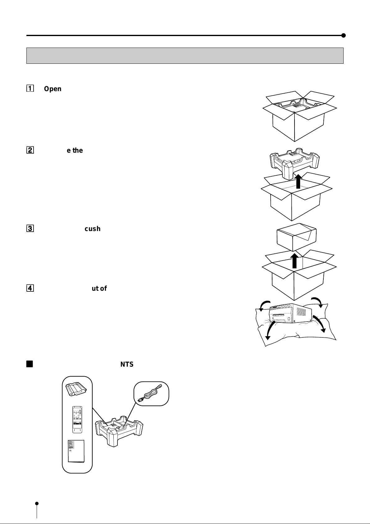
Take the unit out of the box by the following procedures. Make sure to check the contents.
11
1
Open the top of the box.
11
22
2
Remove the accessory box.
22
C
O
C
LO
O
P
R
Y
V
P
ID
R
E
O
O
C
E
S
S
O
R
C
O
C
L
O
O
PY
R
V
PR
ID
E
O
O
C
E
SS
O
R
33
3
Remove the cushion above the unit.
33
44
4
Take the unit out of the box carefully.
44
Make sure to keep the unit horizontally.
Then, unwrap the packing.
22
2
ACCESSORY BOX CONTENTS
22
DISPLAY
COLOR FIELD
PROG.
ADJUST /FRAME
PRINT
Q' ty
MENU
SET
CLEAR
STOP
MEMORY
MONITOR
PAGE
MEMORY
PRINT
Power cord
(CE cable)
O
E
ID
V
R
U
O
L
O
C
R
O
S
S
E
C
O
R
P
Y
P
O
C
Ink cassette
Wired remote control unit
Operation manual
6
FEATURES & FUNCTIONS
1
4
26
5
3
ALARM SHEET PAPER S-VIDEO
7
8
F
11
1
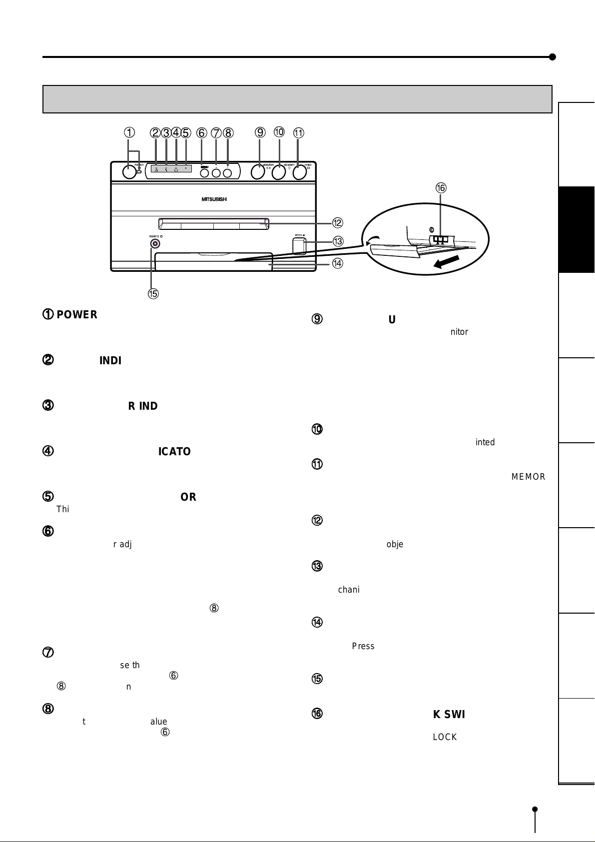
POWER BUTTON (INDICATOR)
11
Press to turn on power. Press again to turn off power.
When the power is turned on, the indicator illuminates.
22
2
ALARM INDICATOR
22
When this unit is overheated, this indicator goes on and
off. When other error occurs, it lights up.
33
3
SHEET ERROR INDICATOR
33
When an error concerning ink sheet occurs, this indicator
lights up.
44
4
PAPER ERROR INDICATOR
44
When an error concerning print paper occurs, this indicator
lights up.
55
5
INPUT SIGNAL INDICATOR
55
This lamp always lights up.
66
6
MENU BUTTON
66
Press for color adjustment. The item will be switched in
order of;
SELECT COLOR/B&W →BR T → CONT → R-SUB → G-SUB
→ B-SUB→ CENTER → CANCEL → SET → SELECT
COLOR/B&W. (When selecting B&W , R-SUB, G-SUB, B-SUB
change to Y -SUB, M-SUB, C-SUB.)
T o go back to the normal screen, press 8PLUS (+) button
while CANCEL or SET is selected.
See page 26.
77
7
MINUS (-) BUTTON
77
Press to decrease the value of each setting item. To set
the value, select SET with 6 MENU button and press
8
PLUS (+) button.
FRONT PANEL
A
9
B
C
D
E
99
9
MONITOR BUTTON
99
Switches the display on the monitor. When this button is
pressed, the picture on the monitor screen switches
between the picture of the input signal (source image) and
the memorized image.
When pressing MEMORY button while holding this button,
print paper will be fed and cut automatically, and the
mechanism will be initialized. Make sure to press
MONITOR button first, or a new image will be memorized.
AA
A
MEMORY BUTTON
AA
Press to memorize the image to be printed.
BB
B
PRINT BUTTON
BB
Press to print the image memorized by the MEMORY
button. The image on the monitor screen switches to the
picture of the input signal.
CC
C
PRINT OUTLET
CC
The printed paper comes out here.
Do not put any objects in front of the outlet.
DD
D
OPEN BUTTON
DD
Press to slide out the printing mechanism. Open the
mechanism to load paper and ink cassette or to clear a
paper jam.
EE
E
TRAY
EE
Holds the printed paper which was come out from the print
outlet. Press down the knob to pull out the tray. Make sure
to pull it out before using this unit.
FF
F
REMOTE TERMINAL
FF
Connects the remote control unit supplied.
G
PRECAUTIONS
FEATURES
CONNECTIONS
PREPARATION
PRINTING
ADJUSTMENTS
SHOOTING
TROUBLE-
88
8
PLUS (+) BUTTON
88
Press to increase the value of each setting item. To set
the value, select SET with 6 MENU button and press this
button.
GG
G
PRINTING UNIT LOCK SWITCH
GG
Locks the printing unit.
Shift the switch to the left (LOCK side) to lock and to the
right (UNLOCK side) to unlock.
This unit is locked when shipping. When transporting this
unit, make sure to lock the unit.
OTHERS
7
6
FEATURES & FUNCTIONS
REAR PANEL
2 5
1
REMOTE
11
1
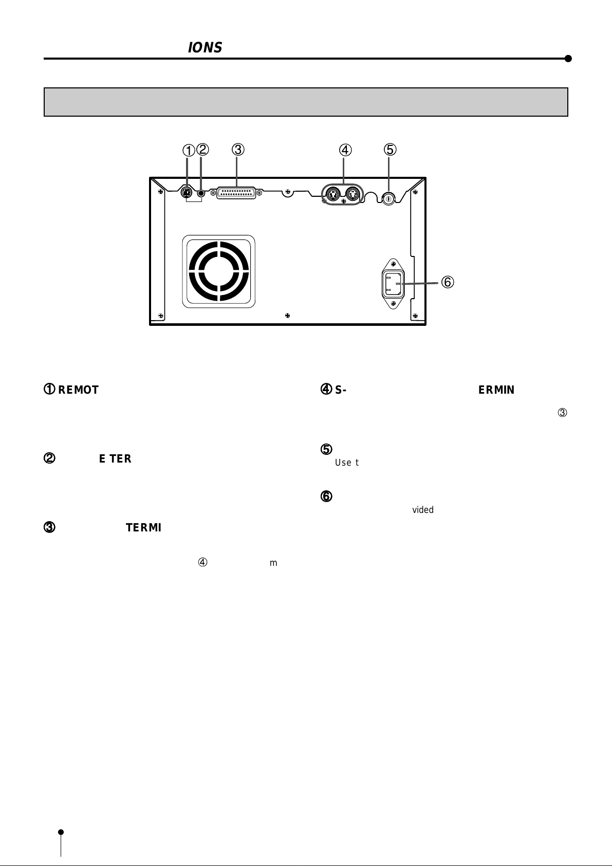
REMOTE TERMINAL 2 (MINI DIN 8 PIN)
11
Memorizing images and printing is available by the remote
signal inputted through this terminal. It is necessary to
make a circuit for remote control unit to use the function.
See pages 20-21.
22
2
REMOTE TERMINAL 1 (STEREO JACK)
22
Memorizing images is available by the remote signal
inputted through this terminal. It is necessary to make a
circuit for remote control unit to use the function. See page
20.
3
CAMERA-IN
4
S-VIDEO/OUT
S-VIDEO/IN
44
4
S-VIDEO INPUT/OUTPUT TERMINAL
44
Use these terminals to connect to S-VIDEO signal
equipment. This terminal can not be used when
CAMERA-IN terminal is used. See page 10.
55
5
VIDEO SIGNAL OUTPUT TERMINAL
55
Use this terminal to connect this unit to VIDEO signal
equipment. See page 10.
66
6
AC LINE SOCKET
66
Connects to the provided power cord. Insert the cord firmly .
VIDEO OUT
AC IN
3
33
3
CAMERA-IN TERMINAL (25 PIN)
33
Use this terminal to connect this unit to a camera.
Do not connect with a personal computer.
This terminal can not be used when 4 S-VIDEO IN terminal
is used. See page 10 for connection.
8
9
A
B
C
D
E
1
2
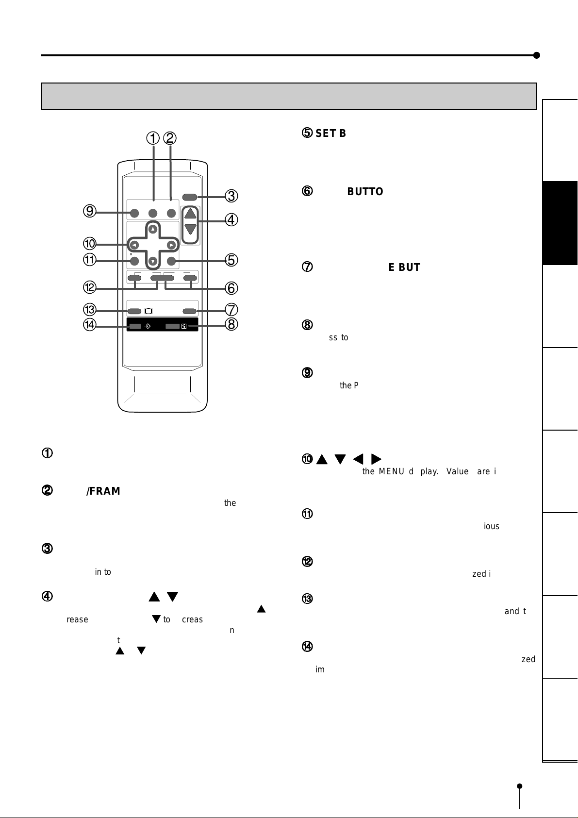
REMOTE CONTROL UNIT
55
5
SET BUTTON
55
Press to display the items of the MENU. Repress to
memorize the values and exit the MENU mode. See pages
22-23.
PRECAUTIONS
DISPLAY
PROG.
COLOR FIELD
ADJUST /FRAME
3
4
PRINT
Q' ty
MENU
CLEAR
SET
STOP
5
6
PRINT
MEMORY
PAGE
7
8
MONITOR
MEMORY
11
1
COLOR ADJUST BUTTON
11
Press to switch black and white / color print.
22
2
FIELD/FRAME BUTTON (LINE ON/OFF)
22
Press to switch on/off of the frame showing the print area
on the display. This button is available when LINE of
MEMORY POSITION menu in MAIN MENU is set to ON.
33
3
DISPLAY BUTTON
33
Press to display the set condition on the monitor screen.
Press again to switch off the display.
66
6
STOP BUTTONS
66
Press to cancel the printing process and start mechanical
initializing. When pressing these buttons during displaying
the main menu, the service menu will be displayed. When
pressing these buttons during stand-by status, the print
quantity is set to 1.
77
7
MEMORY PAGE BUTTON
77
Use to select the image memorized . The memory page is
switched every time this button is pressed. The selected
memory page mark illuminates.
88
8
PRINT BUTTON
88
Press to print the image memorized with the MEMORY
button.
99
9
PROGRAM BUTTON
99
Press the PROG. button to select between 3 types of user
presets. Functions previously set with the MENU can be
stored into one of 3 memories and recalled. Programs
cannot be changed during printing. The selected program
number is displayed for 3 seconds after pressing this
button. It may take longer to change the program.
AA
{{
}}
[[
A
{
,
AA
BB
B
BB
CC
C
CC
}
{{
}}
Use to set the MENU display. Values are increased/
decreased and the cursor position is changed with these
four buttons. See page 24 and 28.
MENU BUTTON
Press to display MAIN MENU used for various settings.
See pages 22-23.
CLEAR BUTTONS
Press to eliminate all or a part of memorized images.
]]
,
[
,
]
[[
BUTTONS
]]
FEATURES
CONNECTIONS
PREPARATION
PRINTING
ADJUSTMENTS
44
4
PRINT QUANTITY
44
Use to set the number of copies to be printed. Press { to
increase the number and } to decrease the number. The
set number of copies is displayed on the monitor screen
for 3 seconds after pressing these buttons. See page 18.
When pressing { or } button during printing, the counter
becomes “1” and continuous printing is cancelled.
{{
{
{{
}}
,
}
BUTTONS
}}
DD
D
MONITOR BUTTON
DD
Press to switch the image of the input signal and the
memorized image being displayed.
EE
E
MEMORY BUTTON
EE
Use to memorize the image to be printed. The memorized
image is displayed on the monitor screen, and then the
image of the input signal is displayed.
SHOOTING
TROUBLE-
OTHERS
9
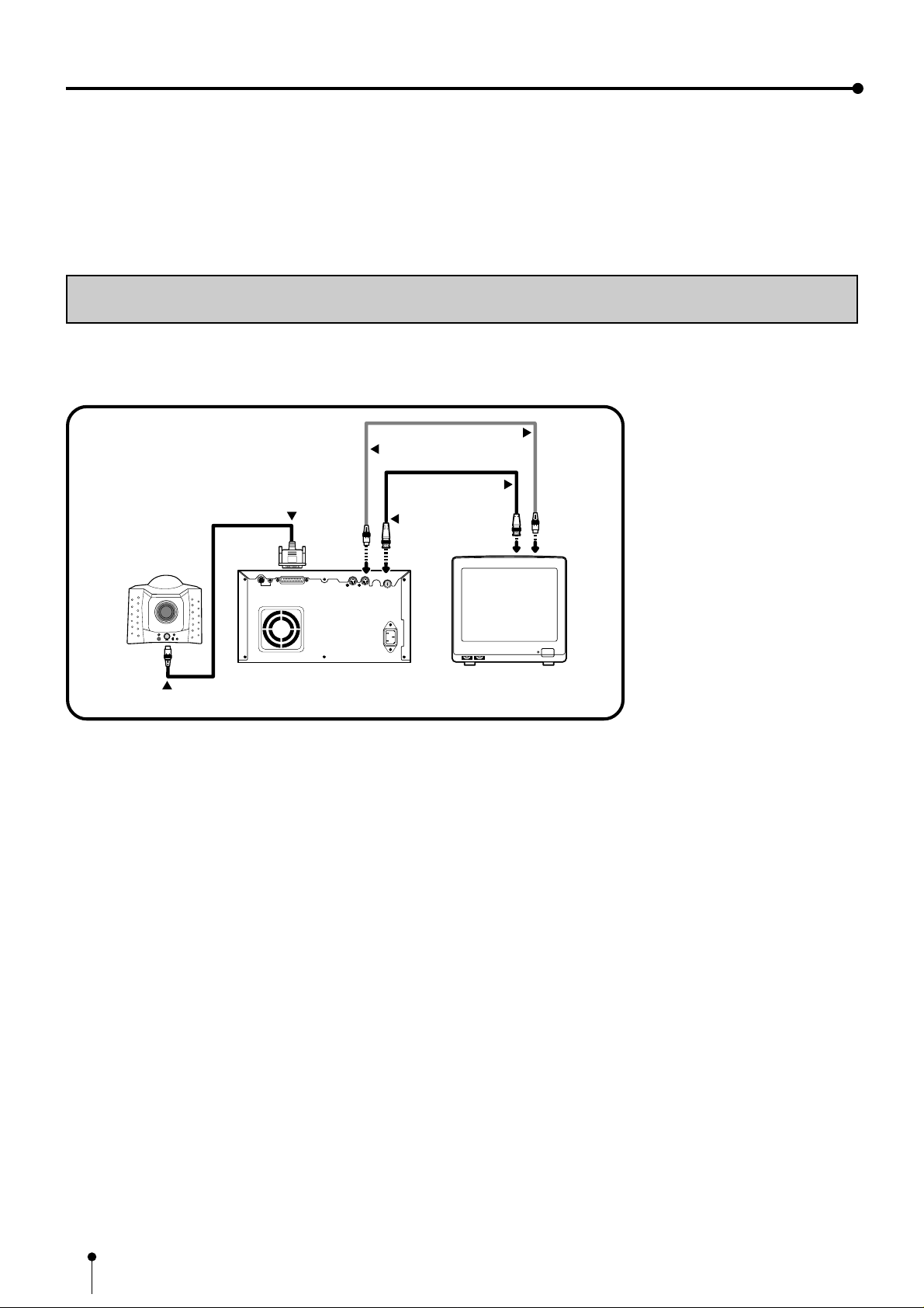
CONNECTIONS
The functions of this unit can be set by the menu screens displayed on the monitor.
Connect this unit with a monitor to check the images to be printed and the images stored in memory.
The following example shows the connection with monitor and camera.
Connect with the necessary signal equipment.
Make sure to turn off the power of the unit and connecting equipment before connection.
CONNECTION WITH MONITOR AND CAMERA
• Make sure to turn off the power before setting.
• Never connect CAMERA-IN terminal to a personal computer.
(EXAMPLE)
To S-VIDEO IN terminal
To S-VIDEO OUT terminal
S-VIDEO OUT
To CAMERA-IN
terminal
To VIDEO IN terminal
To VIDEO OUT terminal
VIDEO OUT
Camera
To camera terminal
CAMERA-IN
REMOTE
S-VIDEO/OUT
S-VIDEO/IN
VIDEO OUT
AC IN
VCP
Monitor (PAL)
10
 Loading...