

Mitsubishi CP910E, CP910 BROCHURE
COLOUR VIDEO COPY PROCESSOR
MODEL
CP910E
OPERATION MANUAL
ALARM SHEET PAPER S-VIDEO
THIS OPERATION MANUAL IS IMPORTANT
TO YOU.
PLEASE READ IT BEFORE USING YOUR
COLOUR VIDEO COPY PROCESSOR.
This video copy processor complies with the requirements of the EC Directive
89/336/EEC, 73/23/EEC, 93/42/EEC and 93/68/EEC.
The electro-magnetic susceptibility has been chosen at a level that gains proper
operation in residential areas, on business and light industrial premises and on
small-scale enterprises, inside as well as outside of the buildings. All places of
operation are characterised by their connection to the public low voltage power
supply system.

CONTENTS
Contents................................................................................................ 2
Safety precautions ................................................................................ 3-5
Special features .................................................................................... 6
Unpacking ............................................................................................. 7
Features and functions ......................................................................... 8-10
Front panel............................................................................................. 8
Rear panel ............................................................................................. 9
Remote control unit................................................................................ 10
Connections .......................................................................................... 11
Connection with a monitor ..................................................................... 11
Connection with video or S-video signal equipment .............................. 11
Before operation.................................................................................... 12-15
Paper sheet set...................................................................................... 12
Unlock the printing unit .......................................................................... 12
Installation of print paper........................................................................ 12-13
Installation of ink sheet .......................................................................... 13-15
Usage and keeping of paper sheet set .................................................. 15
Printing (Basic)...................................................................................... 16-21
Before printing........................................................................................ 16-18
Selecting field/frame ........................................................................... 16
Selecting input signal .......................................................................... 16-17
Selecting print size AUTO/S................................................................ 17-18
Memory print .......................................................................................... 19
Memorizing and printing an image ...................................................... 19
Image memorizing with page increment set on .................................. 19
Number of memory pages .................................................................. 20
Multiple copy or continuous printing.................................................... 21
Printing (Special)................................................................................... 22-27
Multi print ............................................................................................... 22-23
Separate print ........................................................................................ 24
Photo prints............................................................................................ 24
External remote terminal 1..................................................................... 25
External remote terminal 2..................................................................... 26-27
Setting the functions (Menu chart) ........................................................ 28-29
Monitor display chart .............................................................................. 28-29
Adjustments & settings (MAIN MENU).................................................. 30-36
MAIN MENU items................................................................................. 30
Operating MAIN MENU.......................................................................... 30-31
COLOR ADJ (Colour adjustment display).............................................. 32
LAYOUT (Layout setting display) ........................................................... 32-33
PRINT (Print setting display).................................................................. 34
COMMENT (Comment making display)................................................. 35-36
MEMORY POSITION (Memory and position setting display) ................ 36
Adjustments & settings (SERVICE MENU)........................................... 37-43
SERVICE MENU items .......................................................................... 37
Operating SERVICE MENU................................................................... 37
SYSTEM SETUP (System setting display) ............................................ 38
GAMMA ADJ(Gamma level setting display)........................................... 39
LAYOUT2(Layout setting display 2) ....................................................... 39
ANALOG COLOR ADJ (Analog colour adjustment display) .................. 40
INPUT(Input signal setting display)........................................................ 40-41
OUTPUT (Output signal setting display) ................................................ 41
KEY SET (Button function setting display)............................................. 41-42
REMOTE SET(Remote signal setting display) ...................................... 43
PREVIOUS ERROR(Error display) ........................................................ 43
Error messages..................................................................................... 44
Before calling for service....................................................................... 45-46
Overcoming paper jams........................................................................ 47
Cleaning................................................................................................ 48
Spec & options...................................................................................... 49
2

SAFETY PRECAUTIONS
In the interest of safety, please observe the following precautions:
POWER REQUIREMENT
This Colour Video Copy Processor is designed for operation on 220-240V, 50Hz AC. Never connect to any outlet or power
supply having a different voltage or frequency.
WARNING: THIS APPARATUS MUST BE EARTHED.
AVERTISSEMENT: CET APPAREIL DOIT ETRE MIS A LA TERRE.
PROTECTIVE MEASURES
IF ABNORMALITIES ARISE, ....
Use of the unit during emission of smoke or abnormal sounds (without adopting countermeasures) is dangerous. In such a
case, unplug the power cord from the source outlet immediately, and request maintenance service from the sales dealer.
NEVER INSERT ANY OBJECT INTO THE UNIT
Foreign objects of any kind inserted into this unit constitute a safety hazard and can cause extensive damage.
DO NOT PLACE ANYTHING ON THE COLOUR VIDEO COPY PROCESSOR
Heavy objects placed on the Colour Video Copy Processor can cause damage or obstruct proper ventilation.
PROTECT THE POWER CORD
Damage to the power cord may cause fire or shock hazard. When unplugging, hold by the plug only and remove carefully.
DO NOT PLACE WATER CONTAINERS ON THE UNIT
Do not place flower vases, and other water-holding containers on the device. If, for some reason, water seeps to the inside of
the unit, unplug the power cord from the source outlet, and contact the sales dealer. If used without corrective measures, the
unit may be damaged.
“In the interest of safety, avoid handling of liquids near the unit.”
PRECAUTIONS
FEATURES
CONNECTIONS
PREPARATION
DO NOT REMOVE THE CABINET
Touching internal parts is dangerous, besides, it may lead to malfunction. Contact the sales dealer to carry out internal checks
and adjustments. Before opening the cover for eliminating a jammed paper, etc., be sure to disconnect the power cord plug.
UNPLUG THE POWER CORD DURING A LONG ABSENCE
Turn off the MAIN power switch and unplug the power cord during a long absence.
WHEN TRANSPORTING THE UNIT
When transporting the unit, remove the sheet cartridge and paper. Make sure to slide the printing unit lock switch to the lock
position.
BE CAREFUL AROUND PRINT PAPER EXIT SLOT
Do not insert your hand or any material into the paper exit slot during printing.
Do not touch the cutter blade inside the paper exit slot.
Otherwise, your finger will be injured.
DO NOT TOUCH THE THERMAL HEAD
Do not touch your hand to the thermal head (located inside the unit).
The thermal head is heated to high temperature.
This may cause injury.
BE CAREFUL WITH THE PRINTING UNIT
Do not move the unit while the printing unit is sliding out. This may cause injury.
Be careful not to catch your finger in the printing unit while the printing unit is being retracted into the unit.
PRINTING
ADJUSTMENTS
SHOOTING
TROUBLE-
OTHERS
CONNECTION CABLES
Use the provided power cord. When connecting the unit with an equipment with RS-232C interface, use the RS-232C crossover
cable.
3

SAFETY PRECAUTIONS
INSTALLATION LOCATIONS
MAINTAIN GOOD VENTILATION
Ventilation slots and holes are provided on this unit. Place the unit on a hard and level surface and locate at least 10 cm (4
inches) from walls to insure proper ventilation. When putting the unit on the system rack, take a space between the unit and the
back of the rack.
UNSUITABLE LOCATIONS
Avoid shaky places or hot-springs areas where hydrogen sulfide and acidic ions are likely to be generated.
PLACES WITH HIGH HUMIDITY AND DUST
Do not place the unit locations with high humidity and dust. They can cause extensive damage. Avoid places where unit is
likely to be exposed to oily fumes and vapours.
PLACES NOT LIKELY TO BE EXTREMELY HOT
Places exposed to direct sunlight, or near heating appliances can attain extremely high temperatures, which may deform the
cabinet, or can become a prime cause of damage.
PLACE THE UNIT ON A HORIZONTAL LEVEL
The unit is likely to be affected if it is placed in slanted conditions or in unstable places.
PROTECT AGAINST DEW FORMATION
In extremely cold regions, if the unit is moved quickly from an extremely cold place to warmer one, dew is likely to be formed.
If dew is formed, printing is not possible.
OPERATING AMBIENT TEMPERATURE RANGE
The operating ambient temperature range is 41°F - 104°F (5°C to 40°C), and humidity of 20 - 80%. When using the unit on the
system rack, be sure to keep this ambient temperature inside the rack.
FOR LONG OPERATING LIFE
UNSUITABLE MATERIALS FOR THE COLOUR VIDEO COPY PROCESSOR
Coat flaking and deformation are likely to occur if the unit is wiped with chemical dusters, benzine, thinner or any other solvent, if
rubber or PVC items are left in contact with the unit for extended duration, or if the unit is sprayed with insecticide.
CARE OF THE CABINET
Unplug and clean with a soft cloth slightly moistened with a mild soap and water solution. Allow to dry completely before
operating. Never use petroleum base solutions or abrasive cleaners.
HEAD ABRASION
The thermal head, like the video head, wears out. When it is abraded, it becomes hard to print out fine details of the picture. In
such a case, it is necessary to replace the thermal head. Consult with the sales dealer for replacing the head.
CONNECTING DEVICES
Read thoroughly “Operating Precautions” of the instruction booklets for the devices connected with the Colour Video Copy
Processor.
The power cord must be disconnected after printing is over.
CAUTION ON RELOCATING
When transporting this unit, make sure it is not likely to be subjected to impacts. They can be a prime cause for damage.
Further, make sure to disconnect the power cord from the power outlet, and the cables from the connected devices.
4

SAFETY CHECKS
Periods: According to the recommendations of the manufacturer of the medical device.
Scope: a) Visual inspection
Housing, leads, controls, displays, labels/ markings, accessories, operation manual.
b) Function test
Testing of functions (according to operation manual) as well as compatibility and usability of device
and accessories.
c) Electrical test
Testing of electrical safety of the system according to EN60601-1.
High humidity or dust
Avoid locations with high humidity and dust in order to avoid malfunctioning of the device.
Also avoid locations subject to corrosive gasses and smoke.
PRECAUTIONS
FEATURES
Heat
Direct sunlight, heaters or other heat sources may deform the housing and subsequently cause malfunctioning.
TECHNICAL DESCRIPTIONS
The supplier will make available on request such circuit diagrams, component part lists, descriptions, calibration instructions or
other information which will assist the USER's appropriately qualified technical personnel to repair those parts of the
EQUIPMENT which are classified by the manufacturer as repairable.
The use of ACCESSORY equipment not complying with the equivalent safety requirements of this equipment may lead to a
reduced level of safety of the resulting system.
Consideration relating to the choice shall include:
- use of the accessory in the PATIENT VICINITY
- evidence that the safety certification of the ACCESSORY has been performed in accordance to the appropriate EN60601-1
and/or EN60601-1-1 harmonized national standard.
The transportation and storage environmental conditions are :
Temperature : -20°C - +60°C (-4F° - +140°F)
Humidity : 90%RH or less at 40°C (104°F)
Note : The above transportation environmental conditions indicate the storage environmental conditions during transport.
CONNECTIONS
PREPARATION
PRINTING
ADJUSTMENTS
OTHER CAUTIONS
Dust or other foreign matter adhering to the print paper or the sheet cartridge, or deformation resulting from exposure to extremely low or high
temperatures could cause loss of colour, uneven colour or lines, or wrinkles in the print images.
If there is noise or vibration in the VCR still-image or playback picture, the print image may be distorted or the upper part may be crooked.
NOTE:
YOUR UNDERSTANDING IS REQUESTED FOR THE LOSS OF IMAGES IN MEMORY DUE TO THE SUDDEN
OCCURRENCE OF A MALFUNCTION.
This product is to be employed with medical equipment, just for
reference purpose, not for medical diagnostic purpose.
SHOOTING
TROUBLE-
OTHERS
5

SPECIAL FEATURES
SPECIAL FEATURES
AVAILABLE IN VARIOUS MEDICAL FIELDS, INCLUDING ENDOSCOPY DIAGNOSIS
3 kinds of colouring characteristics (gamma curve) are employed, which are the best for medical diagnostic devices, including
endoscope requiring precise images and ultrasound diagnostic equipment etc. The colour is reproducible for each diagnostic
equipment with easy operation. Each gamma curve is adjustable for each user flexibly.
2 PRINT SIZES ARE AVAILABLE ACCORDING TO THE PURPOSE
2 printing sizes, L size (max.110 x 160 mm) and S size (max.110 x 105 mm), are selectable.
MULTI PRINT FUNCTION BY THE CAPACIOUS FRAME MEMORY
As this unit has 3 frame memories, it can store an image during its printing. So the time of diagnosis will be shorten remarkably.
HIGH SPEED PRINTING
Printing speed is approx. 12 seconds (in S size print). Using a rollpaper shortens the time for installing and removing.
LARGE CAPACITY OF PRINTING
Maximum number of printing (S size) is 200 printings per a roll paper. The large capacity of rollpaper printing reduces a time of
exchanges.
POSSIBLE PRINTING IN HIGH QUALITY
High quality print is available in sublimation dye thermal method which is superior in repeatability of images. It also employs 256
gradients and about 16,700,000 colours in each YMC.
325 PPI HIGH RESOLUTION
325 PPI (Pixel Per Inch) high resolution clears the image data. Precise illustrations and photo images can be printed sharply.
MULTI PRINT FOR VARIOUS DEMANDINGS
2, 4, 6 and 16 images of multi print are available. Several multi print modes are selectable according to demanding.
UNIQUE COLOUR IMAGE CONTROL SYSTEM WITH THE IC CHIP BUILT IN INK SHEET ROLLS
By setting the supplied IC chip to ink cassette, the remaining of ink sheet can be displayed. It also controls the colours of the
printing images.
WIDE COMPATIBILITY WITH A VARIETY OF INTERFACE AND SYSTEMS
(1) Input and output control signals from Rear remote interfaces
(2) Fixing function to internal sync. signal avoiding the loop phenomena of sync. signal
(3) Stroboscope sync. function responding to fundus camera system
(4) Image adjusting function such as contrast, brightness, depth etc. of printing image
(5) Capable of storing 3 kinds of setting and adjustment according to each using condition.
6
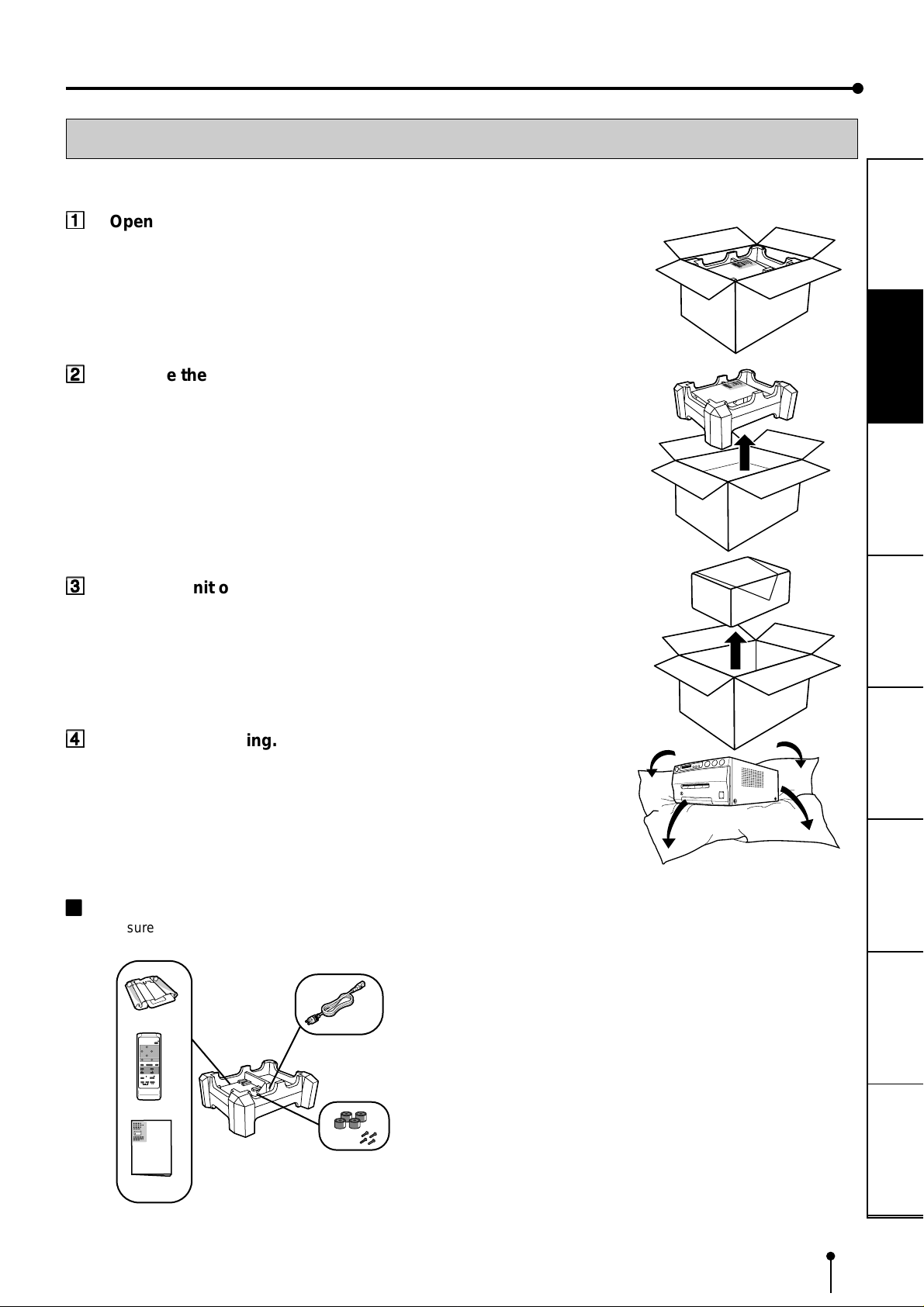
UNPACKING
UNPACKING
Take the unit out of the box by the following procedures. Make sure to check the contents.
11
1
Open the top of the box.
11
22
2
Remove the cushion with contents.
22
Be careful not to drop the contents.
33
3
Take the unit out of the box carefully.
33
Make sure to keep the unit horizontally.
PRECAUTIONS
C
O
C
L
O
O
P
R
Y
V
P
I
D
R
E
O
O
C
E
S
S
O
R
FEATURES
C
O
C
L
O
O
PY
R
V
PR
ID
E
O
O
C
E
SS
O
R
CONNECTIONS
PREPARATION
44
4
Unwrap the packing.
44
22
2
CONTENTS
22
Make sure to check the supplied contents on the cushion.
Power cord
POWER
COMMENT
CHARACTER
CHARACTER
POSITION
COMMENT
START
CLEAR
ON/OFF
/STOP
HIGH
LOW
STROBO
MULTI
IMAGE
L
R
MEMORY
POSITON
PRINT
MEMORY
FIELD
FRAME
MONITOR
Spacers (4)
Screws (4)
O
E
ID
V
R
U
O
L
O
C
R
O
S
S
E
C
O
R
P
Y
P
O
C
Ink cassette
Wired remote control
Operation manual
PRINTING
ADJUSTMENTS
SHOOTING
TROUBLE-
OTHERS
7
FEATURES & FUNCTIONS
FRONT PANEL
1
4
26
ALARM SHEET PAPER S-VIDEO
3
5
7
8
F
11
1
POWER BUTTON (INDICATOR)
11
Press to turn on power. Press again to turn off power.
When the power is turned on, the indicator illuminates.
22
2
ALARM INDICATOR
22
When this unit is overheated, this indicator goes on and
off. When other error occurs, it lights up.
33
3
SHEET ERROR INDICATOR
33
When an error concerning ink sheet occurs, this indicator
lights up.
44
4
PAPER ERROR INDICATOR
44
When an error concerning print paper occurs, this indicator
lights up.
9
A
B
G
C
D
E
pressed, the picture on the monitor screen switches
between the picture of the input signal (source image) and
the memorized image.
When pressing MEMORY button while holding this button,
print paper will be fed and cut automatically, and the
mechanism will be initialized. Make sure to press
MONITOR button first, or a new image will be memorized.
AA
A
MEMORY BUTTON
AA
Press to memorize the image to be printed. When signal
is not inputted, memory is not available.
BB
B
PRINT BUTTON
BB
Press to print the image memorized by the MEMORY
button. The image on the monitor screen switches to the
source image when printing starts. When image is not
memorized, printing is not available.
55
5
INPUT SIGNAL INDICATOR
55
While S-Video signal is selected, this lamp lights up.
66
6
MENU BUTTON
66
Press for color adjustment. The item will be switched in
order of;
SELECT COLOR/B&W→BRT → CONT → R-SUB → G-SUB
→ B-SUB → CENTER[+]→CANCEL[+]→SET[+] → SELECT
COLOR/B&W. (When selecting B&W , R-SUB, G-SUB, B-SUB
change to Y -SUB, M-SUB, C-SUB.)
T o go back to the normal screen, press 8 PLUS(+) button
while SET[+] is selected. See page 32.
77
7
MINUS (-) BUTTON
77
Press to decrease the value of each setting item. To set
the value, select SET[+ ] in the MENU and press 8 PLUS
(+) button.
88
8
PLUS (+) BUTTON
88
Press to increase the value of each setting item. To set
the value, select SET[+] in the 6MENU and press this
button.
99
9
MONITOR BUTTON
99
Switches the display on the monitor. When this button is
CC
C
PRINT OUTLET
CC
The printed paper comes out here.
Do not put any objects in front of the outlet.
DD
D
OPEN BUTTON
DD
Press to slide out the printing mechanism. Make sure to
unlock GPRINTING UNIT LOCK SWITCH. When it is not
working, turn off the power once. Then try to press this
button again. Open the mechanism to load paper and ink
cassette or to clear a paper jam.
EE
E
TRAY
EE
Holds the printed paper which was come out from the print
outlet. Lift the knob to pull out the tray. Make sure to pull it
out before using this unit.
FF
F
REMOTE TERMINAL
FF
Connects the remote control supplied.
GG
G
PRINTING UNIT LOCK SWITCH
GG
Locks the printing unit.
Shift the switch to the left (LOCK side) to lock and to the
right (UNLOCK side) to unlock.
This unit is locked when shipping. When transporting this
unit, make sure to lock the unit.
8
FEATURES & FUNCTIONS
2
1
REMOTE
11
1
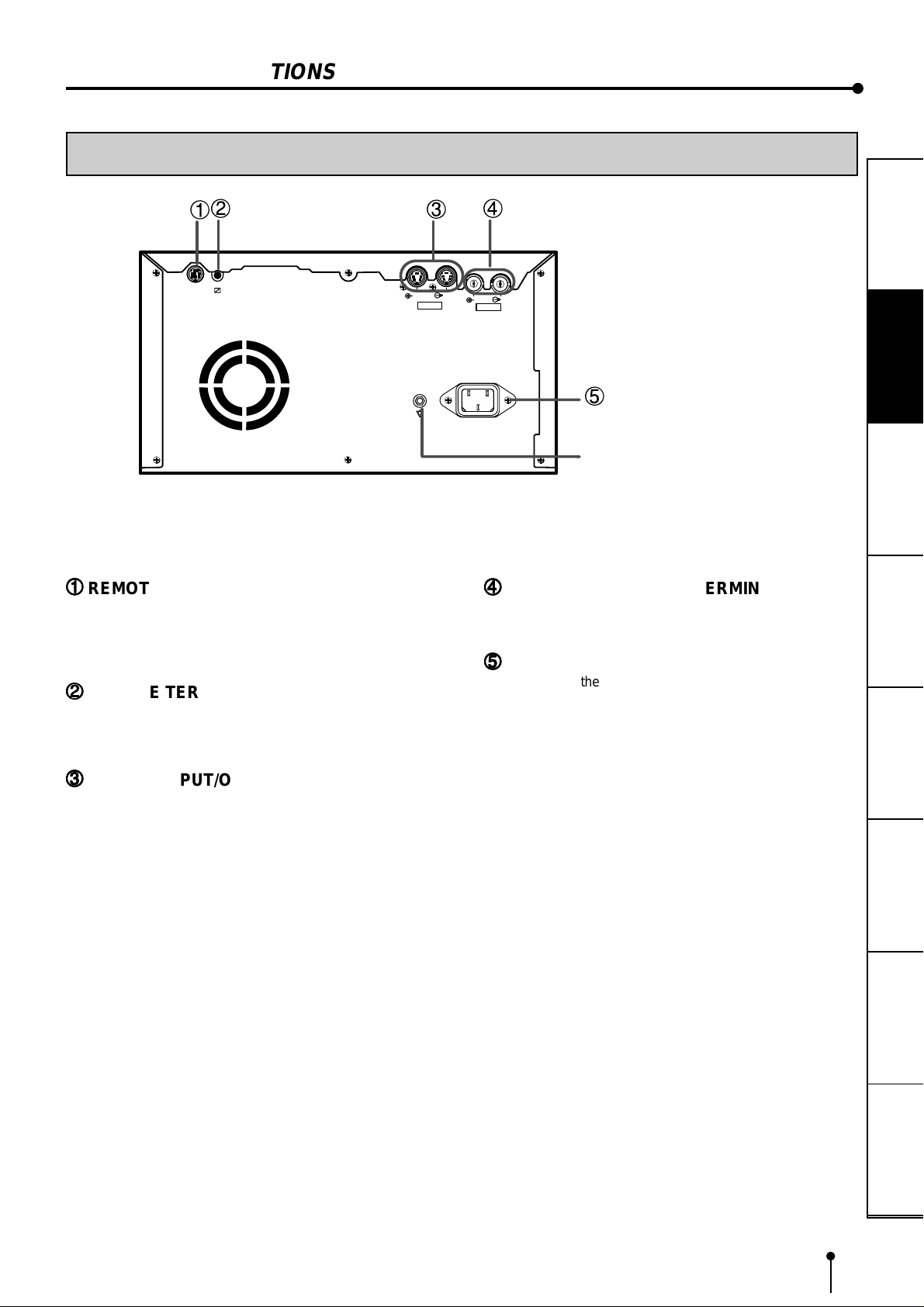
REMOTE TERMINAL 2 (MINI DIN 8 PIN)
11
Memorizing images and printing are available by the remote
signal inputted through this terminal. It is necessary to make
a circuit for remote control to use the function. See pages
26-27.
22
2
REMOTE TERMINAL 1
22
Memorizing images is available by the remote signal
inputted through this terminal. It is necessary to make a
circuit for remote control to use the function. See page 25.
REAR PANEL
3
IN OUT
S-VIDEO
4
OUT
IN
VIDEO
AC LINE
44
4
VIDEO INPUT/OUTPUT TERMINAL
44
Use these terminals to connect this unit to VIDEO signal
equipment. See page 11.
55
5
AC LINE SOCKET
55
Connects to the provided power cord. Insert the cord firmly.
5
Potential equalization connector
This is used to equalize the potential of the equipment
connected to the unit.
For details, refer to the installation instruction of the
equipment to be connected.
PRECAUTIONS
FEATURES
CONNECTIONS
PREPARATION
PRINTING
33
3
S-VIDEO INPUT/OUTPUT TERMINAL
33
Use these terminals to connect to S-VIDEO signal
equipment. See pages 11.
ADJUSTMENTS
SHOOTING
TROUBLE-
OTHERS
9
9
A
B
C
D
E
3
4
6
5
7
8
1
2
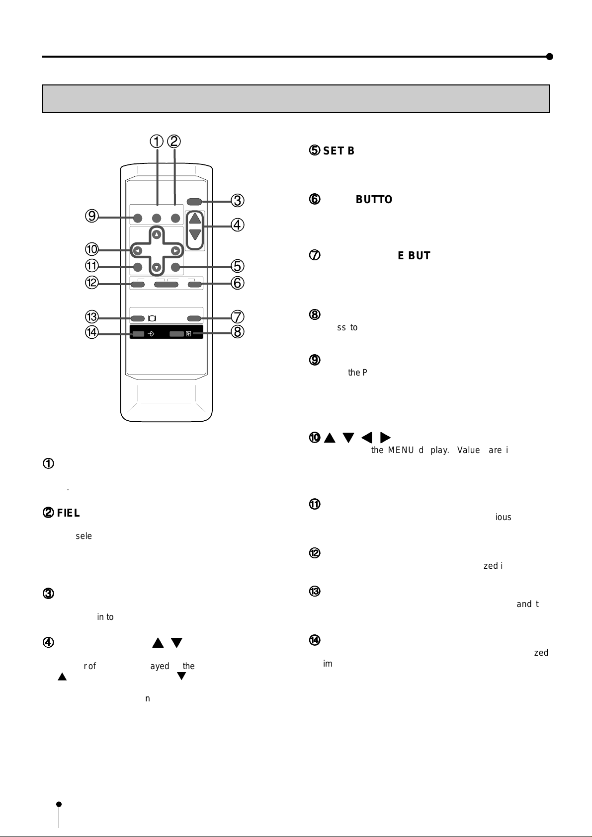
REMOTE CONTROL UNIT
55
5
SET BUTTON
55
Press to go to SAVE PRG. Repress to memorize the values
and exit the MENU mode. See pages 28-29.
DISPLAY
COLOR FIELD
PROG.
ADJUST /FRAME
PRINT
Q' ty
MENU
MONITOR
MEMORY
11
1
COLOR ADJUST BUTTON
11
Press to display the COLOR ADJUST menu. See page
32.
CLEAR
SET
PRINT
STOP
MEMORY
PAGE
66
6
STOP BUTTONS
66
Press to cancel the printing process and start mechanical
initializing. When pressing these buttons during displaying
MAIN MENU, SERVICE MENU will be displayed.
77
7
MEMORY PAGE BUTTON
77
Use to select the image memorized . The memory page is
switched every time this button is pressed. The selected
memory page is shown in green.
88
8
PRINT BUTTON
88
Press to print the image memorized by the MEMORY
button.
99
9
PROGRAM BUTTON
99
Press the PROG. button to select between 3 types of user
presets. Functions previously set with the MENU can be
stored into 1 of 3 memories and recalled. Programs cannot
be changed during printing. It may take longer to change
the program.
AA
{{
}}
[[
A
{
,
AA
}
{{
}}
Use to set the MENU display. Values are increased/
decreased and the cursor position is changed with these
four buttons. These buttons are also used to select one of
memorized images. See page 30 and 37.
]]
,
[
,
]
[[
BUTTONS
]]
22
2
FIELD/FRAME BUTTON
22
Press to switch FRAME and FIELD mode of input signals.
The selected mode is displayed on the monitor screen.
FRAME is good for high quality printing of still images, and
FIELD is good for printing fast movement images.
See page 16.
33
3
DISPLAY BUTTON
33
Press to display the set condition on the monitor screen.
Press again to switch off the display.
44
4
PRINT QUANTITY
44
Use to set the number of copies to be printed. The set
number of copies is displayed on the monitor screen. Press
{
to increase the number and } to decrease the number.
When pressing these buttons during printing, the counter
becomes “1” and continuous printing is cancelled.
See page 21.
{{
{
{{
}}
,
}
BUTTONS
}}
BB
B
MENU BUTTON
BB
Press to display MAIN MENU used for various settings.
See pages 28-29.
CC
C
CLEAR BUTTONS
CC
Press to eliminate all or a part of memorized images.
DD
D
MONITOR BUTTON
DD
Press to switch the image of the input signal and the
memorized image.
EE
E
MEMORY BUTTON
EE
Use to memorize the image to be printed. The memorized
image is displayed on the monitor screen for one second,
then the image of the input signal is displayed.
10
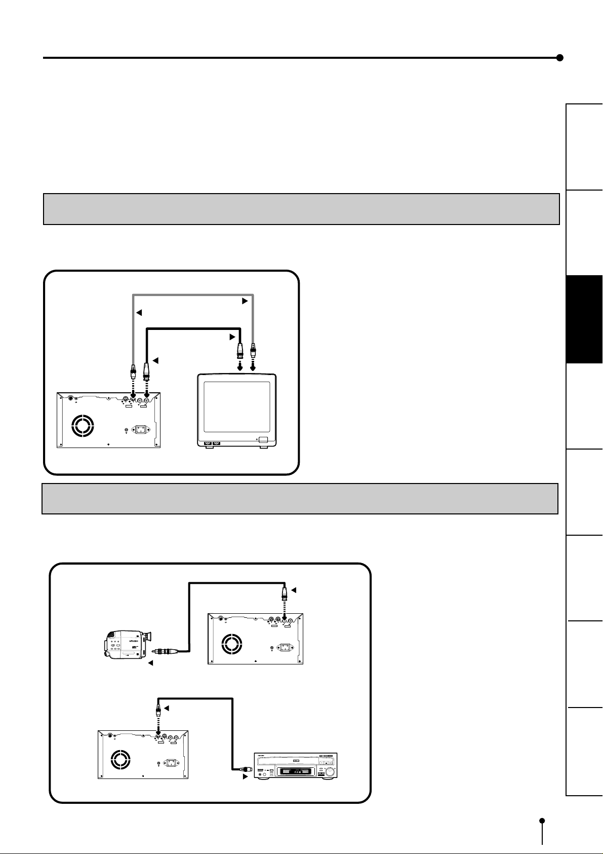
CONNECTIONS
The functions of this unit can be set by the menu screens displayed on the monitor.
• Connection with a monitor
• Connection with VIDEO/S-VIDEO signal equipment
Connect this unit with a monitor to check the images to be printed and the images stored in memory.
The following example shows the connection with a video signal and S-video signal equipment.
Connect with the necessary signal equipment.
Make sure to turn off the power of the unit and connecting equipment before connection.
CONNECTION WITH A MONITOR
Make sure to turn off the power of the unit and connecting equipment before connection.
(EXAMPLE)
To S-VIDEO IN terminal
To S-VIDEO OUT terminal
S-VIDEO OUT
To VIDEO IN terminal
PRECAUTIONS FEATURES
CONNECTIONS
To VIDEO OUT terminal
VIDEO OUT
REMOTE
IN OUT
S-VIDEO
IN OUT
VIDEO
AC LINE
VCP
CONNECTION WITH VIDEO OR S-VIDEO SIGNAL EQUIPMENT
Make sure to turn off the power before setting.
REMOTE
S-VHS HOME CAMERA
S
To VIDEO OUT
VIDEO signal
equipment
terminal
VCP
Monitor
OUT
IN
S-VIDEO
AC LINE
To VIDEO IN terminal
VIDEO IN
IN OUT
VIDEO
PREPARATION
PRINTING
ADJUSTMENTS
SHOOTING
TROUBLE-
To S-VIDEO IN terminal
S-VIDEO IN
OTHERS
REMOTE
OUT
IN
IN OUT
S-VIDEO
VIDEO
AC LINE
To S-VIDEO OUT terminalVCP
S-VIDEO signal equipment
CONFORTABLE LD PLAYER DP-L2000
11
BEFORE OPERATION
Before printing,
1. Unlock the printing unit. (See below)
2. Install the print paper and ink cassette. (pages 12-15)
PAPER SHEET SET
When using this unit for printing, make sure to use the following types of paper sheet and ink sheet set.
22
2
PAPER SHEET SET
22
Product name Ink sheet size No. of prints Usage
CK900S S size 200 Colour print
CK900L L size 130 Colour print
CK900S4P S size 130 Surface-laminated colour print
CK900L4P L size 90 Surface-laminated colour print
CK900S4P(HX)EU S size 130 Surface-laminated colour print for ID photo
CK900L4P(HX)EU L size 90 Surface-laminated colour print for ID photo
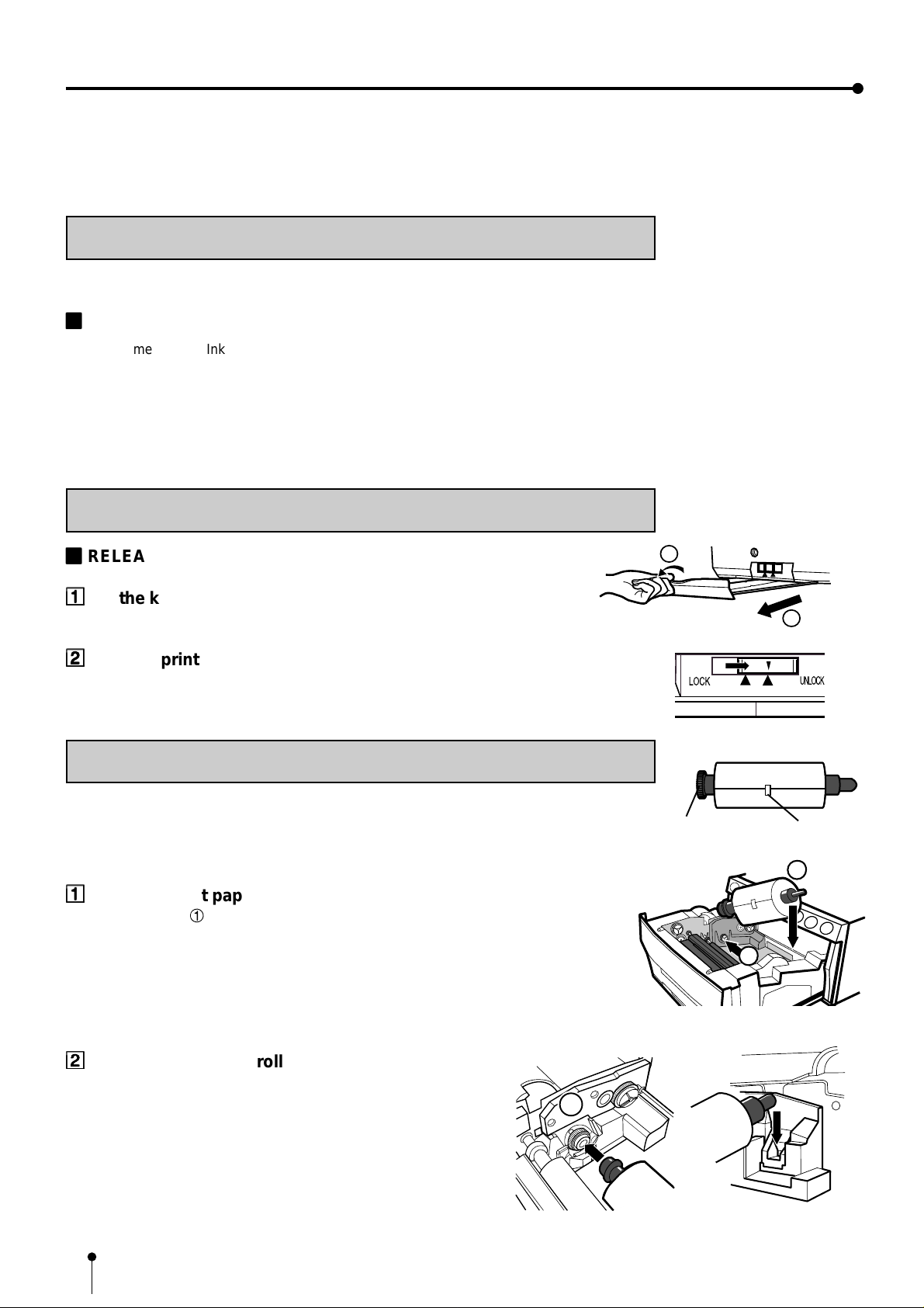
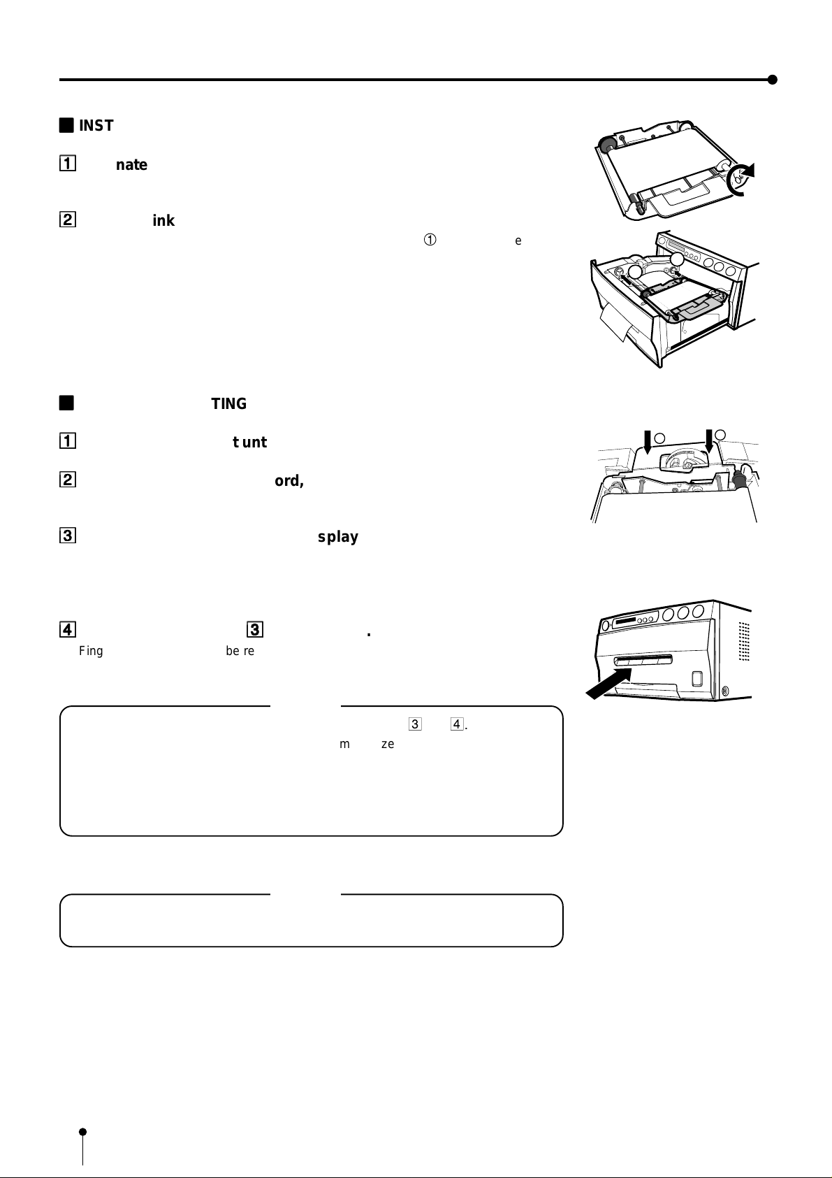
UNLOCK THE PRINTING UNIT
22
2
RELEASING THE PRINTING UNIT LOCK
22
11
1
Lift the knob to pull out the tray.
11
22
2
Shift the printing unit lock switch to the right (UNLOCK). (See page 8.)
22
INSTALLATION OF PRINT PAPER
Do not remove the seal on the print paper yet.
11
1
Insert the print paper roller with gear on the left.
11
Press the folder 1 as shown right, and set the print paper roller.
1
Gear
2
Seal
2
1
22
2
Set the other side of roller without gear.
22
12
Front side
1
Left side Right side
Paper
Paper
Paper
33
3
Remove the seal, and insert the edge of the print paper right
33
below the cover with arrow marks to towards the front panel.
Make sure to insert the paper straight.
44
4
Feed the print paper through the paper outlet with your hand.
44
55
5
Pull the both side of the print paper to eliminate slack.
55
arrow marks
PRECAUTIONS FEATURES
CONNECTIONS
PREPARATION
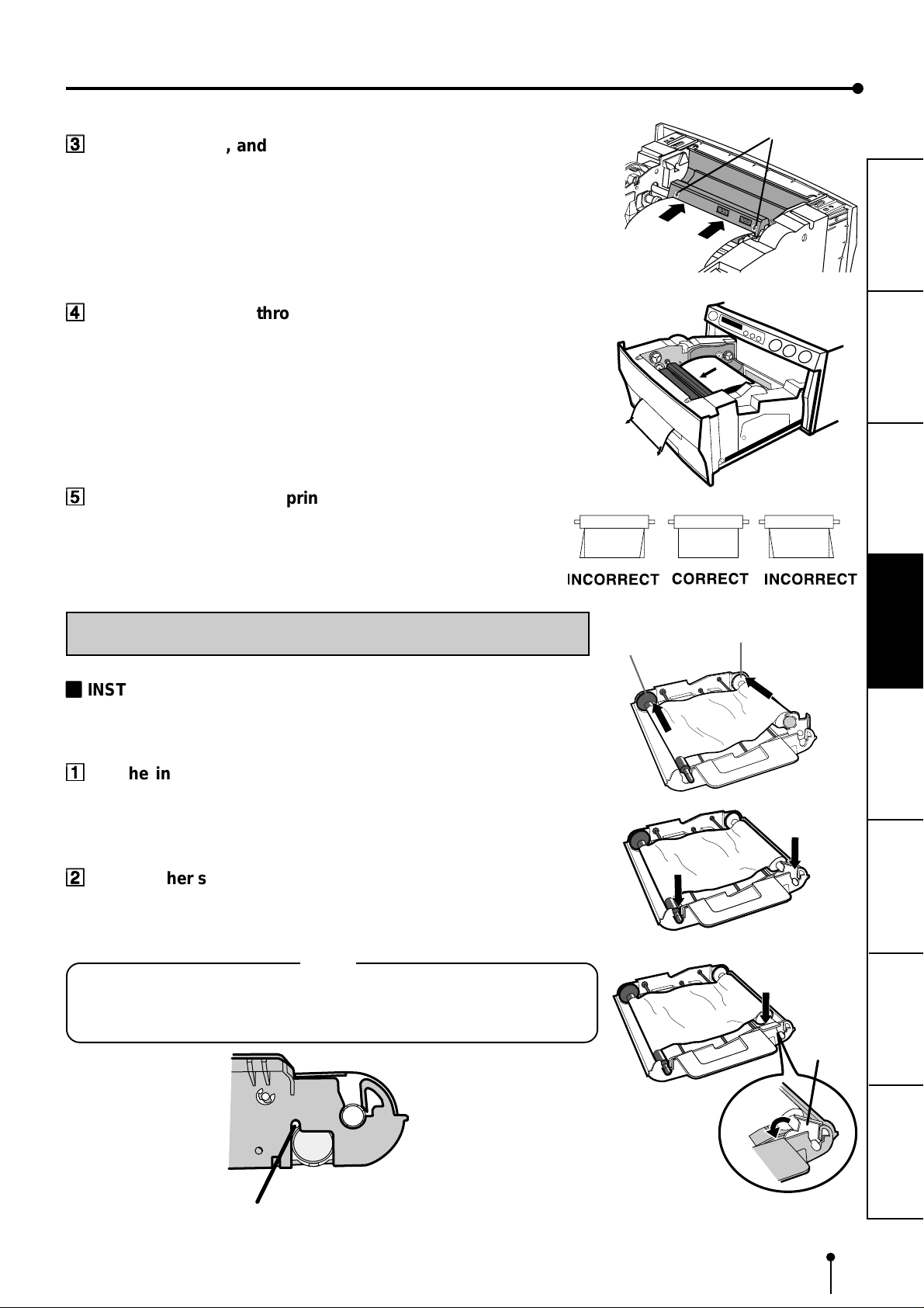
INSTALLATION OF INK SHEET
22
2
INSTALLING THE INK SHEET
22
Load the ink cassette with the ink sheet roll before inserting the ink cassette into the
printer.
11
1
Put the ink sheet rollers with flat tops into the holes of ink
11
cassette.
Put the white roller (rolled with ink sheet) to the ink cassette first.
Then, put the coloured roller (without ink sheet) to the ink cassette.
22
2
Put the other sides of rollers. Set IC at this time.
22
IC is attached to the ink sheet.
Set the IC to the ink cassette as shown right.
NOTE
• Do not remove the IC chip or IC holder from the ink sheet. Removal of the IC
will stop the printer from functioning correctly.
• Set the projected part of the IC holder to the correct position as shown below.
Coloured roller
White roller
IC holder
PRINTING
ADJUSTMENTS
SHOOTING
TROUBLE-
Projected part
OTHERS
13
BEFORE OPERATION
2
2
22
2
INSTALLING THE INK CASSETTE
22
11
1
Eliminate any slack of the ink sheet.
11
Hold the coloured roller and turn the white roller.
22
2
Insert the ink cassette with the ink sheet into its compartment.
22
Put the ink cassette of the ink sheet with flat top side to each 1. Then, set the other
side (with handle) as shown right. When exchanging the ink cassette and so on, remove
it by holding the handle. (See page 47.)
22
2
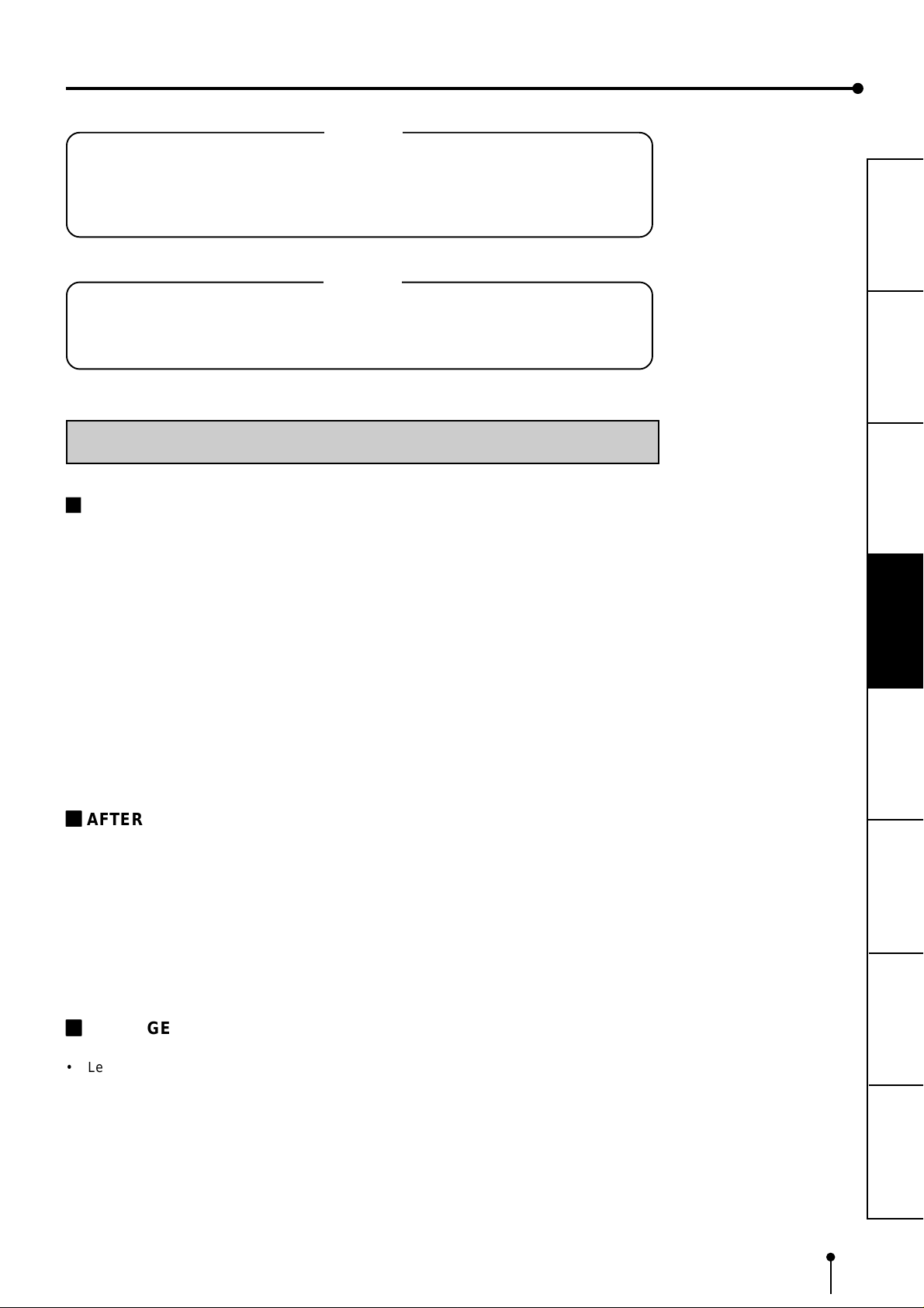
INSERT THE PRINTING UNIT
22
11
1
Push the printing unit until it is locked into place.
11
1
1
22
2
After plugging the power cord, press POWER button on the front
22
panel.
33
3
After the set conditions are displayed on the monitor, press
33
MEMORY button about 1 second with holding MONIT OR button on
the front panel.
The print paper is automatically cut after feeding about 10 cm (4 inches).
44
4
Repeat the above step
44
Fingerprints and dust can be removed by feeding the print paper. The printing unit is
initialized.
33
3
once or twice.
33
NOTE
• Make sure to press MONITOR button first for operating 3 and
Pressing MEMORY button first operates to memorize the images. When
exchanging the printing paper or ink cassette during using the unit, the
recorded images may be erased by pressing MEMORY button first.
• Do not feed the print paper more than 2 times. Doing so will not allow the
number of prints indicated on page 12 to be printed.
4.
The installation of print paper and ink cassette is completed.
NOTE
An IC is built in the ink sheet. This is the IC chip, not a battery.
This IC can be thrown away as normal waste.
14
NOTE
If the power is turned on and AUTO FEED&CUT on SYSTEM SETUP menu is set to ON,
“SET PAPER” disappears when print paper is set. (For AUTO FEED&CUT setting, refer
to page 38.) After inserting ink sheet and closing the printing unit, the print paper is
automatically fed and cut twice.
NOTE
Take the print paper one by one after completing printing. Pull out the tray completely
when using it. If you fail to do so, paper jamming may occur.
Put the tray back when finishing printing.
USAGE AND KEEPING OF PAPER SHEET SET
2
BEFORE PRINTING
PRECAUTIONS FEATURES
CONNECTIONS
• Fingerprints or dust on the paper’s surface may degrade print quality and cause paper
jams. Immediately after the paper is replaced, 2-3 images may be printed with a blank
part due to hand’s dust or oil. Refer to Pages 12-13.
• When print paper is rapidly transferred from a cool place to a hot place, vapour or dew
will be generated on the paper’s surface causing paper jams or degraded print quality.
Leave the print paper in the room to stabilize its temperature before using it.
• When print paper and ink sheet run out during printing, the printing operation stops and
the error messages such as “CHANGE PAPER” and “CHANGE INK” is displayed on
the monitor. Set new ink sheet or print paper. Refer to Page 44.
22
2
AFTER PRINTING
22
• When the printed paper is touched by a wet hand, the print may be discoloured.
• Fading may occur if the print-face is exposed to organic chemical agents which may
affect print paper (e.g. alcohol, ester, ketone based).
• Fading will be accelerated upon contact with PVC-based materials (e.g. adhesive
tapes, rubber erasers, etc.).
• Avoid storing prints in direct sunlight or places with high humidity.
PREPARATION
PRINTING
ADJUSTMENTS
SHOOTING
TROUBLE-
22
2
STORAGE
22
• Leaving the print paper in contact with PVC-based materials causes color of print
paper to come off and to be stained.
• Never store print paper in places that are close to heater, hot, humid or dusty.
Keep print paper in a place where;
Temperature : 5°C - 30 °C
Humidity : 20 % - 60 %RH
OTHERS
15
 Loading...