

Mitsubishi CP700E Operation Manual
COLOUR VIDEO COPY PROCESSOR
MODEL
CP700E
OPERATION MANUAL
THIS OPERATION MANUAL IS IMPORTANT
TO YOU.
PLEASE READ IT BEFORE USING YOUR
COLOUR VIDEO COPY PROCESSOR.
POWER
OPEN
REMOTE
MEMORY
PRINT
MONITOR
CP700
This video copy processor complies with the requirements of the EC
Directive 89/336/EEC, 73/23/EEC, 93/42/EEC and 93/68/EEC.
The electro-magnetic susceptibility has been chosen at a level that
gains proper operation in residential areas, on business and light
industrial premises and on small-scale enterprises, inside as well as
outside of the buildings. All places of operation are characterised by
their connection to the public low voltage power supply system.

1
1. Contents................................................................................................................. 1
2. Precautions.........................................................................................................2-4
3. Preparations before operation ..........................................................................5-13
4. Connection with external equipment...............................................................14-21
5. Features and functions ...................................................................................22-26
6. Printing procedures
Basic prints.................................................................................................27-36
7. Setting the functions
Menu display chart .....................................................................................38-41
Main menu .................................................................................................42-53
Making a comment.....................................................................................53-58
Memory switch menu .................................................................................59-64
8. Printing procedures
Special prints..............................................................................................65-83
9. Troubleshooting
Error messages and countermeasures...................................................... 84-85
Overcoming paper jams .................................................................................. 85
Before calling for service............................................................................86-87
10. Options ( Sold separately ) ................................................................................ 88
11. Specifications.....................................................................................................89
1. Contents
11
11
1 Contents
11
11
1 Accessories
0 Operation manual ( 2 )
0 Power cord ( 1 )
0 Lithium battery (CR2025 ) ( 1 )
0 Remote control ( 1 )
0 Spacer ( 4 )
0 Additional sheet
• Installing print paper and ink sheet
0 Ink-cassette ( 1 )

2
In the interest of safety , please observe the following precautions:
POWER REQUIREMENT
This Colour Video Copy Processor is designed for operation on 220-240V , 50Hz AC. Never connect to any outlet or power supply having a
different voltage or frequency.
WARNING: THIS APPARATUS MUST BE EARTHED.
AVERTISSEMENT: CET APPAREIL DOIT ETRE MIS A LA TERRE.
PROTECTIVE MEASURES
IF ABNORMALITIES ARISE, .....
Use of the unit during emission of smoke or abnormal sounds (without adopting countermeasures) is dangerous. In such a case, unplug the
power cord from the source outlet immediately, and request maintenance service from the sales dealer.
NEVER INSERT ANY OBJECT INTO THE UNIT
Foreign objects of any kind inserted into this unit constitute a safety hazard and can cause extensive damage.
DO NOT PLACE ANYTHING ON THE COLOUR VIDEO COPY PROCESSOR
Heavy objects placed on the Colour Video Copy Processor can cause damage or obstruct proper ventilation.
PROTECT THE POWER CORD
Damage to the power cord may cause fire or shock hazard. When unplugging, hold by the plug only and remove carefully.
DO NOT PLACE WATER CONTAINERS ON THE UNIT
Do not place flower vases, and other water-holding containers on the device. If, for some reason, water seeps to the inside of the unit, unplug the
power cord from the source outlet, and contact the sales dealer. If used without corrective measures, the unit may be damaged.
“In the interest of safety, avoid handling of liquids near the unit.”
DO NOT REMOVE THE CABINET
Touching internal parts is dangerous, besides, it may lead to malfunction. Contact the sales dealer to carry out internal checks and adjustments.
Before opening the cover for eliminating a jammed paper, etc., be sure to disconnect the power cord plug.
UNPLUG THE POWER CORD DURING A LONG ABSENCE
Turn off the MAIN power switch and unplug the power cord during a long absence.
WHEN TRANSPORTING THE UNIT
When transporting the unit, remove the sheet cartridge and paper from the paper cassette, and insert the protective cushion into its
compartment. Make sure to screw the printing unit down.
BE CAREFUL AROUND PRINT PAPER EXIT SLOT
Don't insert your hand or any material into the paper exit slot during printing.
Don't touch the cutter blade inside the paper exit slot.
Otherwise, your finger will be injured.
DO NOT TOUCH THE THERMAL HEAD
Do not touch your hand to the thermal head (located inside the unit).
The thermal head is heated to high temperature.
This may cause injury.
USE THE LITHIUM BA TTERY CORRECTLY
If the lithium battery is used incorrectly, it may cause injury or fire.
• Be sure to observe the correct polarity while installing the battery.
• Keep away from children.
• Do not disassemble or burn the battery.
2. Precautions

3
BE CAREFUL WITH THE PRINTING UNIT
Don't move the unit while the printing unit is sliding out. This may cause injury.
Be careful not to catch your finger in the printing unit while the printing unit is being retracted into the unit.
CONNECTION CABLES
Use the provided power cord and the composite video signal cable. When connecting the unit with an equipment with RS-232C interface, use
the RS-232C cross-over cable.
INST ALLA TION LOCATIONS
MAINTAIN GOOD VENTILATION
Ventilation slots and holes are provided on the top, sides and bottom of this unit. Place the unit on a hard and level surface and locate at least
10 cm from walls to insure proper ventilation. When putting the unit on the system rack, take a space between the unit and the back of the rack.
UNSUIT ABLE LOCATIONS
Avoid shaky places or hot-springs areas where hydrogen sulfide and acidic ions are likely to be generated.
PLACES WITH HIGH HUMIDITY AND DUST
Do not place the unit locations with high humidity and dust. They can cause extensive damage. Avoid places where unit is likely to be exposed to
oily fumes and vapours.
PLACES NOT LIKEL Y T O BE EXTREMELY HOT
Places exposed to direct sunlight, or near heating appliances can attain extremely high temperatures, which may deform the cabinet, or can
become a prime cause of damage.
PLACE THE UNIT ON A HORIZONTAL LEVEL
The unit is likely to be affected if it is placed in slanted conditions or in unstable places.
PROTECT AGAINST DEW FORMATION
In extremely cold regions, if the unit is moved quickly from an extremely cold place to warmer one, dew is likely to be formed.
If dew is formed, printing is not possible.
OPERA TING AMBIENT TEMPERATURE RANGE
The operating ambient temperature range is 5°C- 40°C, and humidity of 20-80%. When using the unit on the system rack, be sure to keep this
ambient temperature inside the rack.
FOR LONG OPERATING LIFE
UNSUIT ABLE MATERIALS FOR THE COLOUR VIDEO COPY PROCESSOR
Coat flaking and deformation are likely to occur if the unit is wiped with chemical dusters, benzine, thinner or any other solvent, if rubber or PVC
items are left in contact with the unit for extended duration, or if the unit is sprayed with insecticide.
CARE OF THE CABINET
Unplug and clean with a soft cloth slightly moistened with a mild soap and water solution. Allow to dry completely before operating. Never use
petroleum base solutions or abrasive cleaners.
HEAD ABRASION
The thermal head, like the video head, wears out. When it is abraded, it becomes hard to print out fine details of the picture. In such a case, it is
necessary to replace the thermal head. Consult with the sales dealer for replacing the head.
CONNECTING DEVICES
Read thoroughly “Operating Precautions” of the instruction booklets for the devices connected with the Colour Video Copy Processor.
The power cord must be disconnected after printing is over.
2. Precautions

4
CAUTION ON RELOCATING
When transporting this unit, make sure it is not likely to be subjected to impacts. They can be a prime cause for damage. Further, make sure to
disconnect the power cord from the power outlet, and the cables from the connected devices.
SAFETY CHECKS
Periods: According to the recommendations of the manufacturer of the medical device.
Scope: a) Visual inspection
Housing, leads, controls, displays, labels/ markings, accessories, operation manual.
b) Funcitonslity test
Testing of functions (according to operation manual) as well as compatibility and usability of device
and accessories.
c) Electrical test
Testing of electrical safety of the system according to EN60601-1.
High humidity or dust
Avoid locations with high humidity and dust in order to avoid malfunctioning of the device.
Also avoid locations subject to corrosive gasses and smoke.
Heat
Direct sunlight, heaters or other heat sources may deform the housing and subsequently cause malfunctioning.
TECHNICAL DESCRIPTIONS
The supplier will make available on request such circuit diagrams, component part lists, descriptions, calibration instructions or
other information which will assist the USER's appropriately qualified technical personnel to repair those parts of the
EQUIPMENT which are classified by the manufacturer as repairable.
The use of ACCESSORY equipment not complying with the equivalent safety requirements of this equipment may lead to a
reduced level of safety of the resulting system.
Consideration relating to the choice shall include:
- use of the accessory in the PATIENT VICINITY
- evidence that the safety certification of the ACCESSORY has been performed in accordance to the appropriate EN60601-1
and/or EN60601-1-1 harmonized national standard.
The transportation and storage environmental conditions are :
Temperature : -20°C - +60°C (-4F° - +140°F)
Humidity : 90%RH or less at 40°C (104°F)
Note : The above transportation environmental conditions indicate the storage environmental conditions during transport.
OTHER CAUTIONS
Dust or other foreign matter adhering to the print paper or the sheet cartridge, or deformation resulting from exposure to extremely low or high
temperatures could cause loss of colour, uneven colour or lines, or wrinkles in the print images.
If there is noise or vibration in the VCR still-image or playback picture, the print image may be distorted or the upper part may be crooked.
NOTE:
YOUR UNDERSTANDING IS REQUESTED FOR THE LOSS OF IMAGES IN MEMOR Y DUE TO THE SUDDEN
OCCURRENCE OF A MALFUNCTION.
As for paper sheet set, refer to page 7 “Installing print paper and ink sheet”.
2. Precautions
This product is to be employed with medical equipment, just for reference
purpose, not for medical diagnostic purpose.
5
1 Removing the fixed screw on the printing unit and protective cushion Pages 5 - 6
2 Installing the lithium battery Page 6
,Power for memorizing the day and present time are supplied by a lithium battery . Before using this unit
install the lithium battery.
3 Installing the print paper and ink cassette. Pages 7 - 9
, Install the print paper.
, Install the cassette with ink sheet.
4 Setting the present time Pages 10 - 13
, Set the day and present time to print on the lower part of the print.
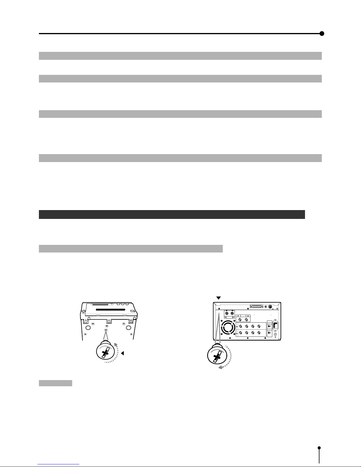
1 Removing the fixed screw on the printing unit and protective cushion Pag
When using the unit for the first time, remove the fixed screw on the printing unit and protective cushion.
1 Remove the fixed screw on the printing unit.
,There is a fixed screw at the bottom of the printing unit.
1 Remove the fixed screw with a screwdriver or coin.
2 Set the removed screw to the hole on the rear panel for keep the screw.
Attention:
, Keep the removed fixed screw by setting it to the hole on the rear panel. This screw is required when transporting
this unit.
, Make sure you set the fixed screw to the bottom of the unit when transporting the printer.
Fixed screw
R G/G+SYNC B H+V-SYNC
R G/G+SYNC B H+V-SYNC
IN
OUT
S-VIDEO
AC LINE
VIDEO
75Ω
HIGH
75Ω
HIGH
IMPEDANCE
SYNC.
RGB
RS-232C
Stored position
REMOTE
12
3. Preparations before operation
6
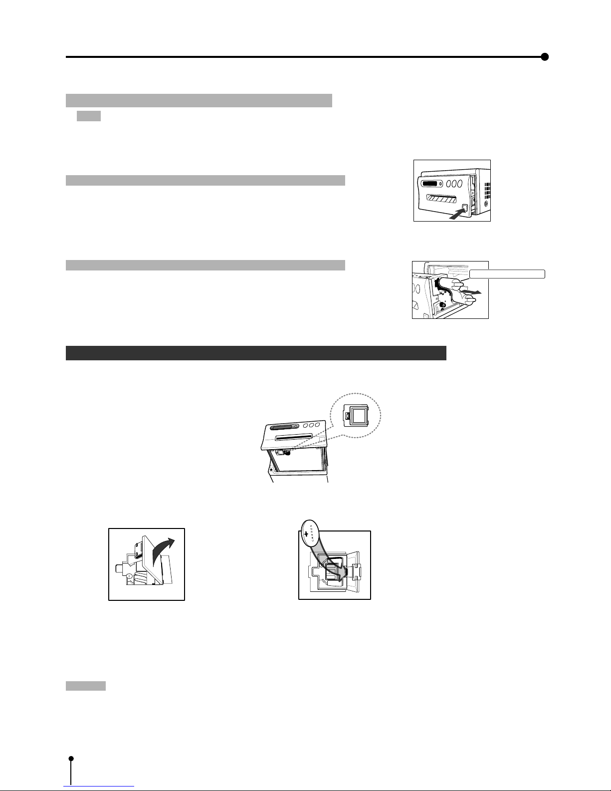
1 Open the door. 2 Install the battery with the (+) side facing out.
3 Close the door.
1 Remove the protective cushion.
Note: Unplug the power cord from outlet for safety.
1 Press the OPEN button on the front panel.
Printing unit will slide out.
Attention
}}
}}
}
, Do not touch the thermal head.
Fingerprints or dust on the thermal head will degrade the print quality.
2 Pull out the protective cushion from the right side.
Attention
}}
}}
}
, Keep the protective cushion for transporting this unit.
, It is very important to transport this printer with the protective cushion
installed so as not to damage the printing unit.
2 Installing the lithium battery
Power for memory of day and present time are supplied by a lithium battery.
Install the lithium battery ( accessory CR2025) by the following procedure after plugging the VCP.
{ Install the lithium battery to the folder.
, If the installed battery is dead or a battery has been installed incorrectly, the built-in clock and power loss listing will not
function properly.
, When changing the battery, pry the battery out of the holder with a sharp object.
, After changing the battery, set the present time and day .
Note:
, Take care of the battery. Refer to pages on lithium battery precaution.
, The setting before installing the battery is not valid. When operating this unit without any settings, the strobe function
may not be operated.
Folder
Protective cushion
3. Preparations before operation
, If the installed battery is dead or a battery has been installed incorrectly, the built-in clock and power loss listing will not
function properly.
, When changing the battery, pry the battery out of the holder with a sharp object.
, After changing the battery, set the present time and day .
Note:
, Take care of the battery. Refer to pages on lithium battery precaution.
, The setting before installing the battery is not valid. When operating this unit without any settings, the strobe function
may not be operated.
7
3 Installing print paper and ink sheet
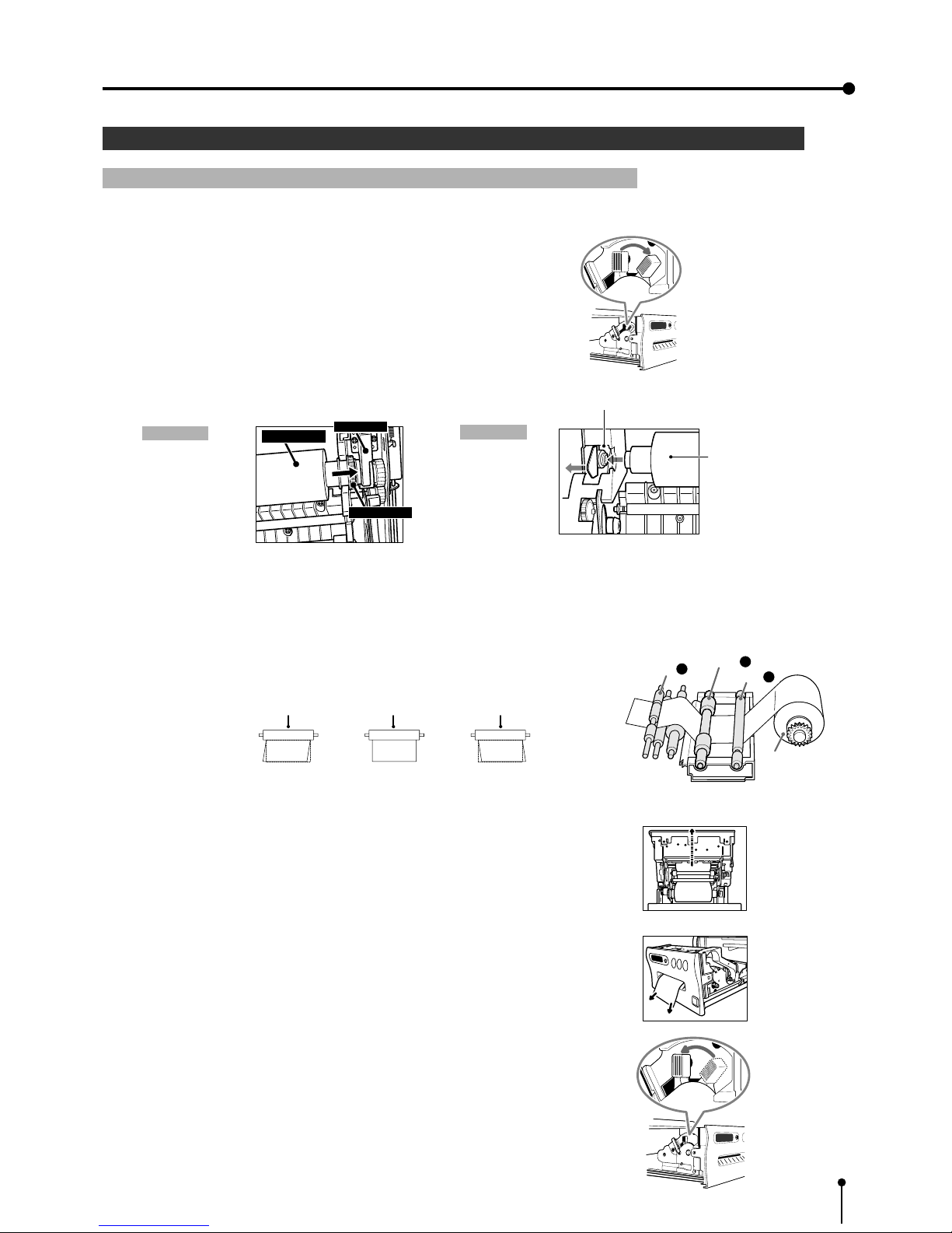
1 Installation procedure of print paper
1 Move the knob on the printing unit to the direction indicated by the arrow.
2 Insert the print paper in the position as shown below.
Place the gear to the right side.
Right side Left side
• Set the paper roll first on the right side paper holder.
• Set the paper roll on the left side paper holder.
3 Insert the print paper between roller 1 and 2.
4 Insert the edge of the print paper to roller 3.
Be sure to insert the paper straight.
5 Feed the print paper through the exit slot straight with your hand.
6 Pull the print paper to eliminate slack.
7 Move the knob on the side of the printing unit to the direction as
indicated by the arrow.
3. Preparations before operation
Print paper
Folder
Insert
Folder
Print paper
Roller
Roller
Roller
Paper
Paper Paper
INCORRECT CORRECT INCORRECT
1
Roller
2
Roller
3
Roller
Print paper

8
3. Preparations before operation
1 Install the ink sheet
Install the ink sheet to the ink cassette before installing the sheet cassette to the unit.
1 Set the black roller of the ink sheet to ink cassette as shown right A, B.
2 Set the thin stick of white roller to the ink cassette as shown right C.
3 Set the thick stick of white roller of the ink cassette as shown right D, E.
In the step 3, turn the roller and set the notch of the roller side to the hole of
the cassette .
Install the roller by putting the notch through the hole.
1Install the ink cassette
1 Eliminate any slack of the ink sheet.
Push the black roller and turn the white roller.
2 Insert the ink cassette with the ink sheet into its compartment.
Insert the ink cassette with the knob side toward you.
1Set the printing unit
1 Push the printing unit until it is locked into place.
2 After plugging the power cord, press the “POWER” button on the front panel.
3 Press the MEMORY ( ) button for about 1 second while pressing the
MONITOR (
) button on the front panel .
, The print paper is automatically cut after sending by about 10cm.
4 Repeat 3 step.
(Fingerprints and dust can be removed by feeding the print paper. The
printing unit is initialized.)
Attention
}}
}}
}
, When setting the print paper, the set paper is a little pulled into the unit. Take care that any object is not pulled into
the unit with the print paper.
, In 2~3steps, press the “MONITOR” first. If MEMORY button is pressed first, the stored in memory may be cleared.
, Do not feed the print paper (2~3 steps) more than 2 times. Doing so will not arrow the number of prints indicated on page 9
to be printed.
, If the print paper is pulled out too much at installing, an error may occur with the display “PAPER JAM 12”. In this case, initialize
this unit again. (2~3 steps)
0 The installation of the print paper and ink sheet is completed.
White roller
Black roller
A
B
C
E
E
D
notch
a
b

9
3. Preparations before operation
1 Print paper and ink sheet
Attention
}}
}}
}
, The following types of paper sheet sets are available.
Use our original consumable. We can not guarantee the failure of using others.
Ink sheet
Product name Ink sheet size Number of prints Usage
PK700S S size 200 sheets For 3 color use
PK700L L size 130 sheets For 3 color use
Print-paper
Product name Print size Number of prints Usage
CK700 S / L size S size:200 sheets For 3 color use
L size:130 sheets
K65H S / L size S size:200 sheets For thermal printing
L size:125 sheets
K65HM S / L size S size:200 sheets For thermal printing
L size:125 sheets
Print-paper/ Ink sheet
Product name Print size Number of prints Usage
CK700S4P S size 110 sheets For 3 color use (Surface-coated paper)
CK700L4P L size 75 sheets For 3 color use (Surface-coated paper)
CK700SC S size 200 sheets For 3 color use (sticker)
CK700LC L size 130 sheets For 3 color use (sticker)
CK710SPC S size 200 sheets For 3 color use (16-division pre-cut sticker)
CK710LPC L size 130 sheets For 3 color use (16-division pre-cut sticker)
Ink sheet /Ink cassette
Product name Print size Number of prints Usage
PKC700S S size 200 sheets For 3 color use
PKC700L L size 130 sheets For 3 color use
Note:
, Please observe the following precautions.
Precautions before printing
0 Fingerprints or dust on the paper’s printing surface may degrade print quality and cause paper jams. Immediately after the
paper is replaced, 2-3 images may be printed with a blank part due to hand’s dust or oil.
0 When print paper is rapidly transferred from a cool place to a hot place, vapor or dew is generated on the paper’s surface
causing paper jams or degraded print quality. Leave the print paper in the room to stabilize its temperature before using it.
0 When print paper and ink sheet runs out during printing, the printing operation stops and the error message “PAPER
EMPTY” or “SHEET EMPTY” is displayed. Replace the print paper and ink sheet with a new one.
0 If paper feeding is repeated while installing the print paper, the indicated number of prints may not be done.
After printing
0 When the printed paper is touched by a wet hand, the print may be discolored.
0 If the paper absorbs non-volatile organic solvents ( alcohol, ester, ketone etc.) the print may be discolored.
0 Discoloration of prints will be accelerated if the print paper comes into contact with soft vinyl chloride such as transparent
tape etc.
Storage
0 Store the prints in a place with low humidity free from direct sunlight.
0 Leaving the print paper in contact with PVC-based materials causes color of print paper to come off and to be stained.
0 Avoid direct sunlight and placing the printed paper near a heater.
Note:
0 If the print paper is installed for two or more days, the prints may be rolled after printing. There is no cause for alarm
because the print paper is rolled on the inside of the printing unit.
10
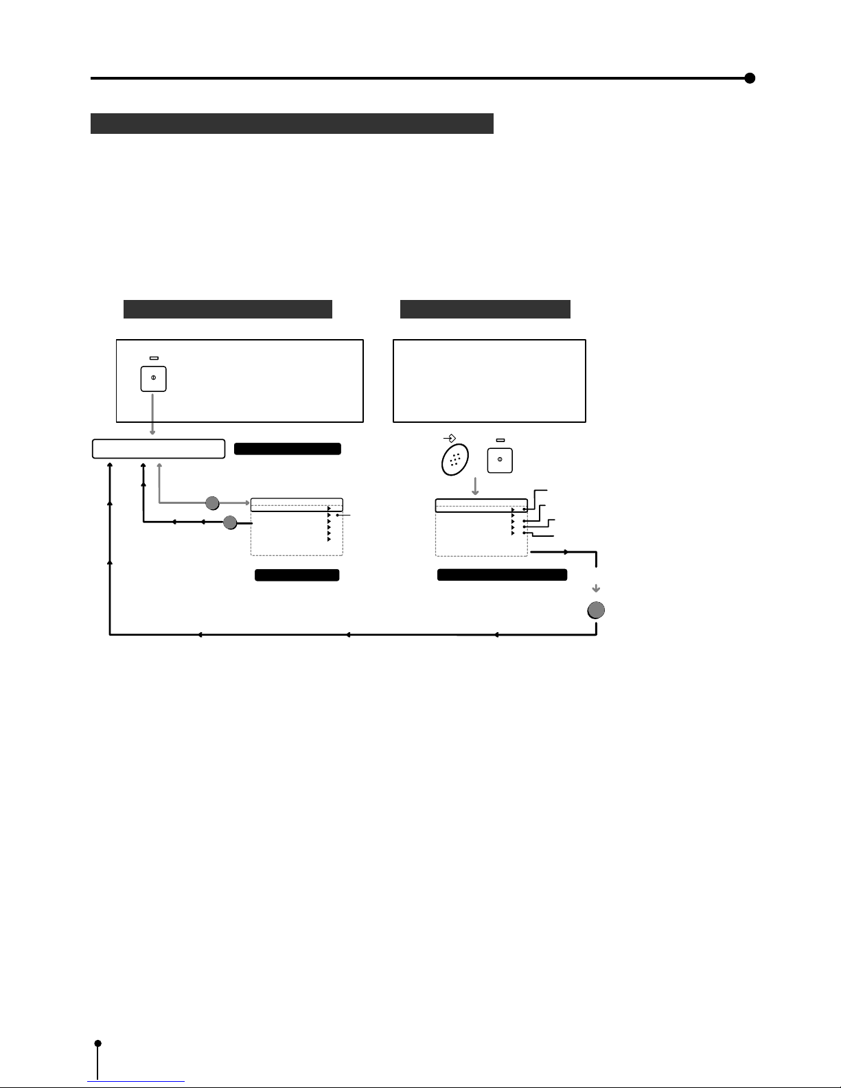
Menu display
When setting the day and present time , use the menu on the LCD display.
Also use the menu when selecting each setting after connecting an external device or selecting the print size (S /L).
, There are 2 menus, Main menu and Memory SW menu.
, Each menu is displayed as shown below.
MAIN MENU Memory SW menu
0 Setting the present time
Refer to pages 11-13.
0 Setting the polarity.
Refer to pages 15-16 .
0 Setting the print paper.
Refer to pages 31-32 .
0 Setting the baud rate.(RS-232C)
Refer to pages 19-21 .
0 Setting input signal.
Refer to pages 29-30.
, For each setting, refer to the pages above.
Use the remote control to set the functions.
3. Preparations before operation
Memory SW Main Menu
1.TIME ADJ : PUSH [ ]
2.KEY SET : PUSH [ ]
3.SIGNAL ADJ : PUSH [ ]
4.PRINT SET : PUSH [ ]
5.SYSTEM SET : PUSH [ ]
CHANGE : OK CANCEL INIT
MEMORY
POWER
+
Pressing the POWER button to
display MEMORY SW menu
while pressing MEMORY button.
Press the menu button to
display the Main menu after
pressing POWER button.
Memory SW menu
MENU
NORMAL PRG.1 Q'ty 1
Page:A FIELD RGB
MAIN menu
Normal display
SET
POWER
Selecting the
input signal
Setting the day and present time
Setting the polarity
Setting the print paper
Setting the baud rate (
RS-232C)
SET
OK
Main Menu
1.COLOR ADJ : PUSH [ ]
2.SIGNAL SET
: PUSH [ ]
3.ADDITIONAL
: PUSH [ ]
4.PRINT : PUSH [ ]
5.COMMENT : PUSH [ ]
6.SYSTEM : PUSH [ ]
SAVE PRG : 1 / 2 / 3
11
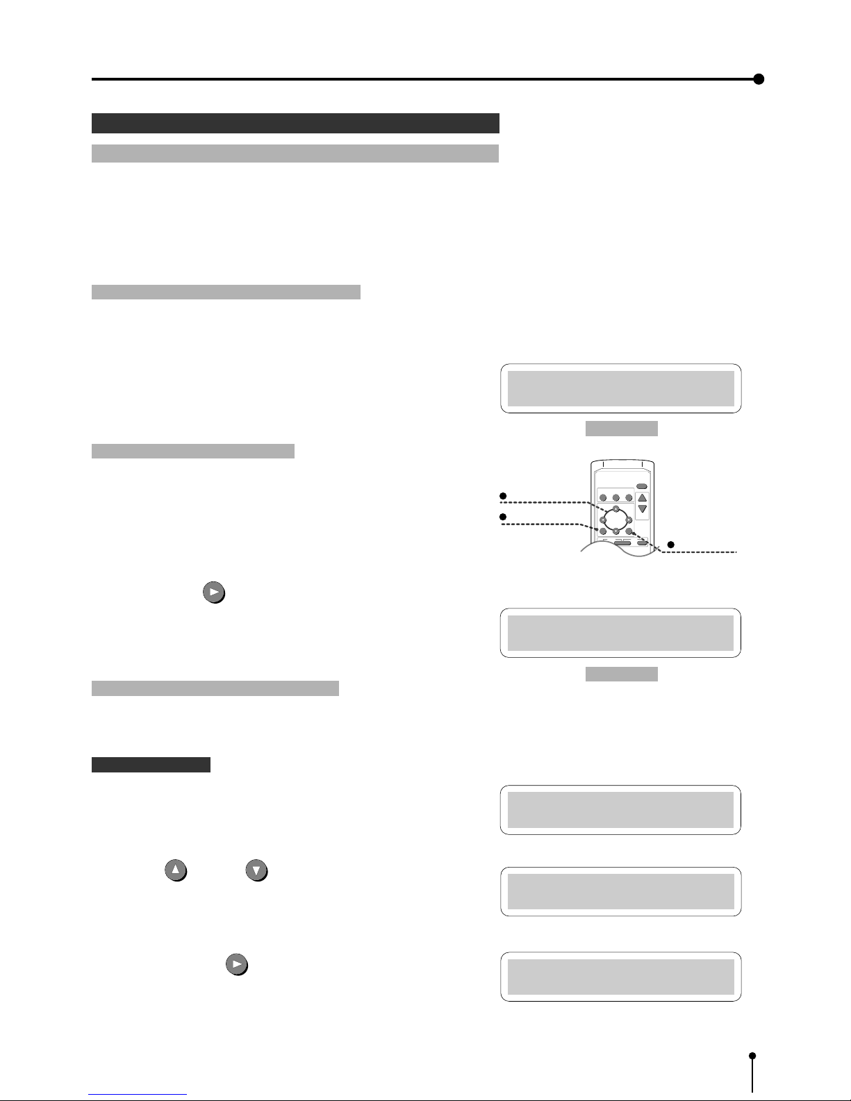
, Set the day and present time in the menu on the monitor display or LCD
display.
A . Display “Memory SW Main Menu”
, Make sure to turn off power.
1 Press the POWER button while pressing the MEMORY button. Menu
display for button function “Memory SW Main Menu” is displayed.
B . Display “Time Adj Menu”
All these functions are operated with the remote control using the
menus displayed on the monitor screen.
2 Press the RIGHT
button.
, “Time Adj Menu” is displayed.
Set the day and present time on the menu.
4 Setting the present time
1 Setting the day and present time
Set the day and present time on the lower part of the print by the following
procedure.
3. Preparations before operation
Memory SW Main Menu
1.TIME ADJ :PUSH[>]
PRINT
Q' ty
SET button
SHIFT buttons
MENU button
PROG.
MENU
CLEAR STOP
SET
COLOR FIELD
ADJUST /FRAME
DISPLAY
-
+
Time Adj Menu
DATE : 28
Time Adj Menu
MONTH : 01
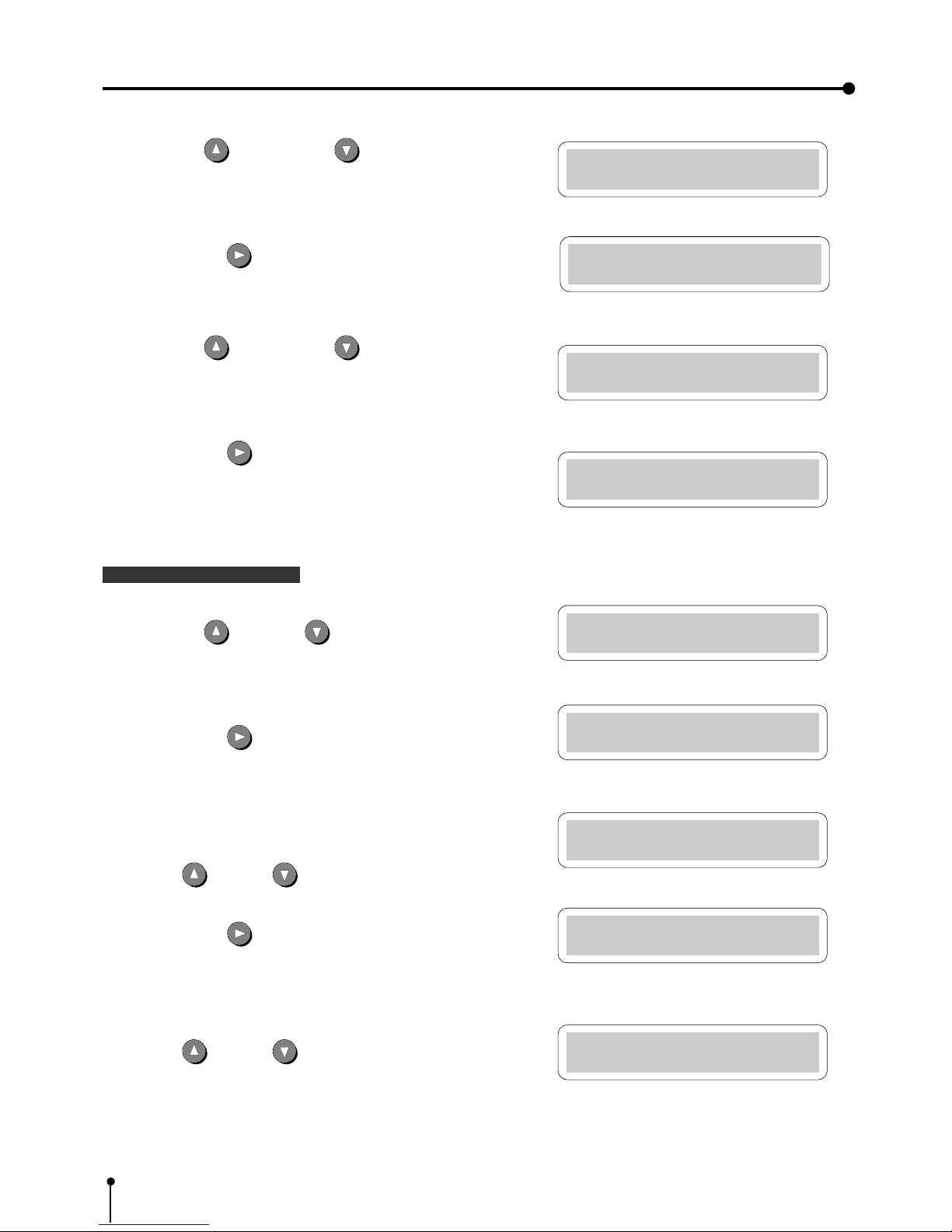
C . Setting the day and present time
• Setting part is displayed in red on the monitor.
Setting the day
, “DATE” is indicated on the LCD display.
3 Press UP or DOWN button to change the value.
4 Press the shift button .
Date is set and “MONTH” is displayed on the LCD .
Time Adj Menu
DATE : 01
Time Adj Menu
DATE : 01
LCD display
LCD display
12
5 Press the UP button or DOWN button to change the value.
6 Press the RIGHT button. The month is set and display the “YEAR”.
, The “YEAR” is displayed on the LCD .
7 Press the UP button or DOWN button to change value.
8 Press the RIGHT button.
, The day is set and the present time is displayed.
The “HOUR” is displayed on the LCD .
Setting the present time
9 Press the UP and DOWN button to change the value.
A Press the RIGHT button.
, “HOUR” is set and the “MINUTE” is displayed.
The “MINUTE” is displayed on the LCD.
B Press UP or DOWN button to change the value.
C Press the RIGHT
button.
, The “MINUTE” is set and the “SECOND” is displayed .
The “SECOND” is displayed on the LCD.
D Press UP
or DOWN button to change the value.
3. Preparations before operation
Time Adj Menu
MONTH : 08
Time Adj Menu
YEAR : 95
Time Adj Menu
HOUR : 00
Time Adj Menu
HOUR : 05
Time Adj Menu
MINUTE: 00
Time Adj Menu
MINUTE: 10
Time Adj Menu
SECOND: 00
Time Adj Menu
SECOND: 10
Time Adj Menu
YEAR : 99
13
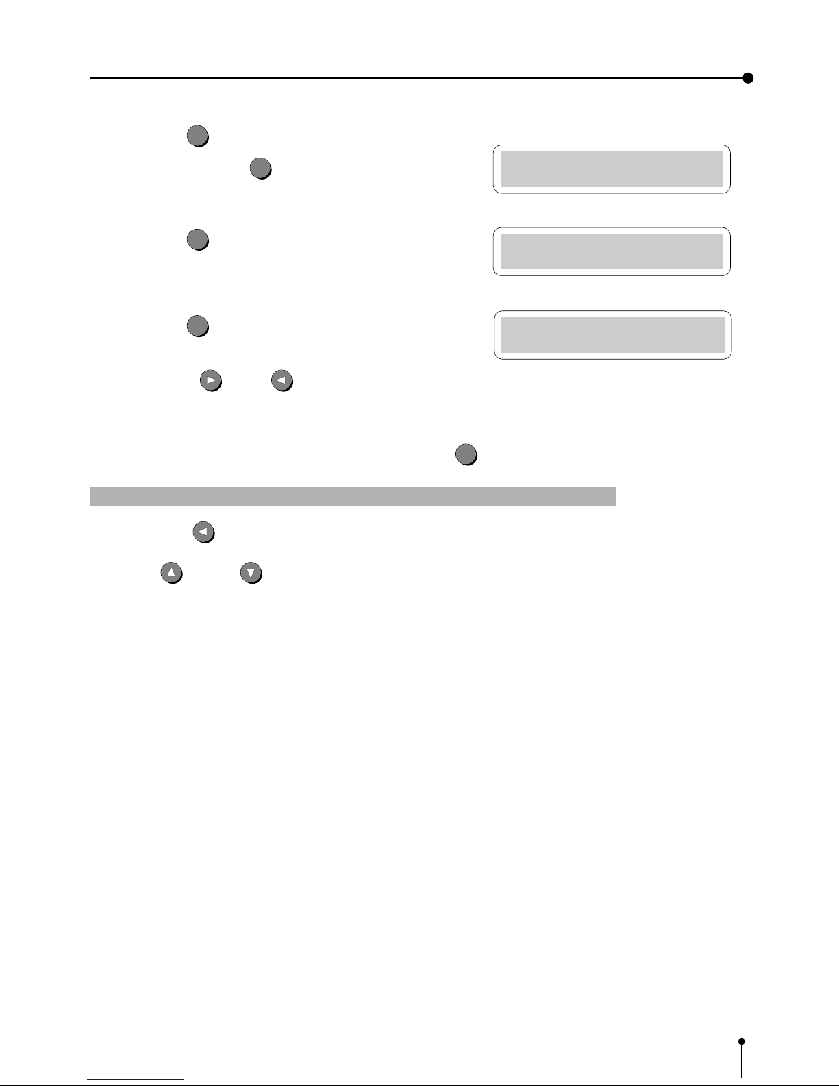
, The source image is shown when selecting OK and press the SET
SET
button.
1 Change the date and present time setting
, When the LEFT button is pressed during setting the date and present time, the cursor moves to the previous step.
Press UP
or DOWN button to change the value.
, Date and present time setting is completed.
3. Preparations before operation
Time Adj Menu
SECOND: 31
Memory SW Main Menu
1.TIME ADJ :PUSH[>]
Memory SW Main Menu
CHANGE: OK
E Press the SET
SET
button.
, When pressing the SET
SET
button, the present time function will
be started.
F Press the SET
SET
button.
, “Memory SW Main Menu” display is shown.
G Press the SET
SET
button.
“CHANGE : OK” is selected.
, Press the RIGHT or LEFT button to select “OK” or
“CANCEL” according to the setting.
14
4. Connection with external equipment
The functions of this unit can be set with the menu screens displayed on the monitor.
1 Connection with Monitors Pages 14 - 16
Explains how to connect with a monitor.
Explains the setting of sync. polarity.
, When the sync. polarity of a monitor differs from the initial setting of this unit, the image on the monitor may not be
displayed correctly. In this case, set the sync. polarity according to the monitor.
When the image is displayed on the monitor correctly , the setting is not required.
2 Connection with VIDEO/S-VIDEO (Y/C separate VIDEO) signal equipment Page 17
Explains how to connect with a video signal equipment.
Explains how to connect with a S-video signal equipment.
3 Connection with RGB Analog Signal equipment Page 18
Explains how to connect with a RGB analog signal equipment.
4 Connection with RS-232C equipment Pages 19 - 21
Explains how to connect with a RS-232C equipment.
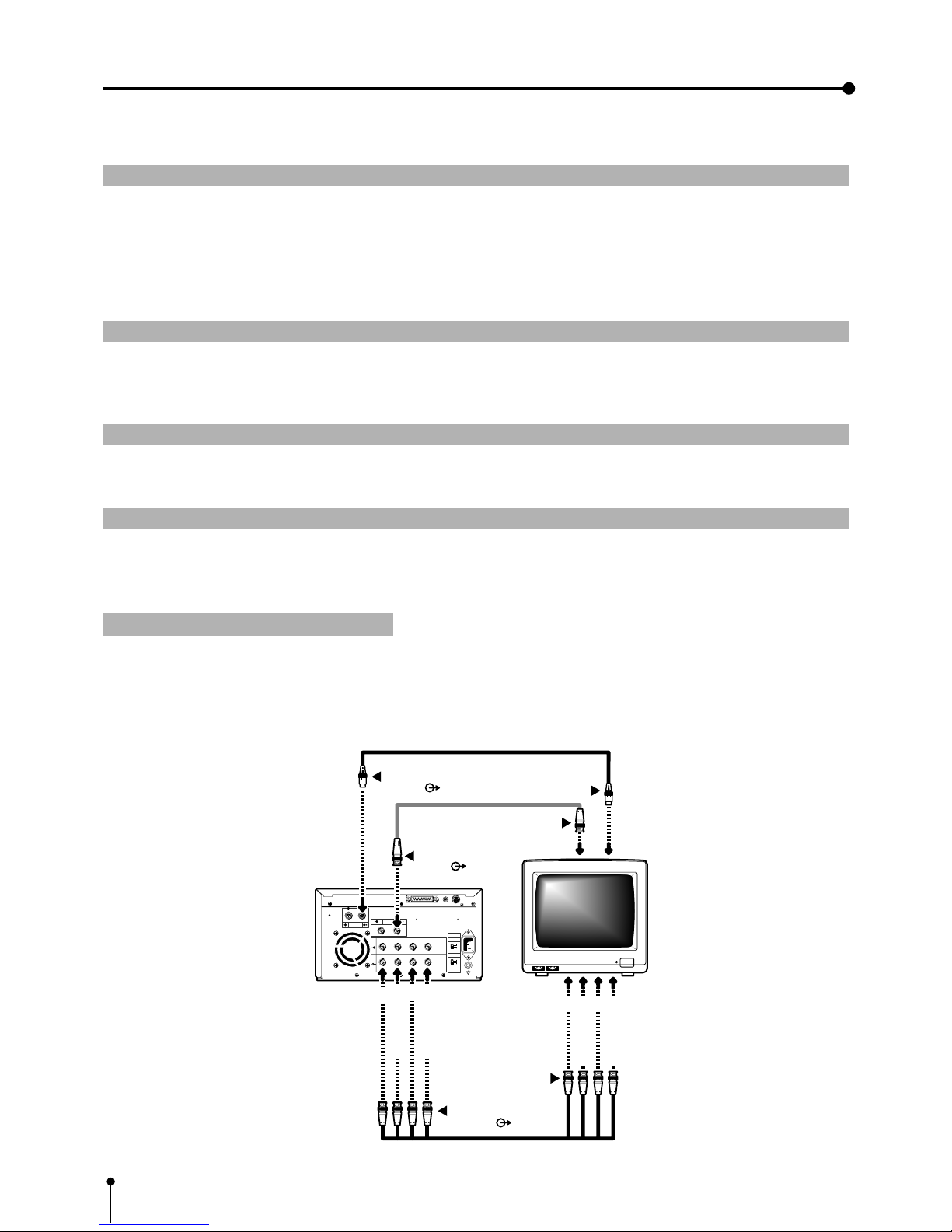
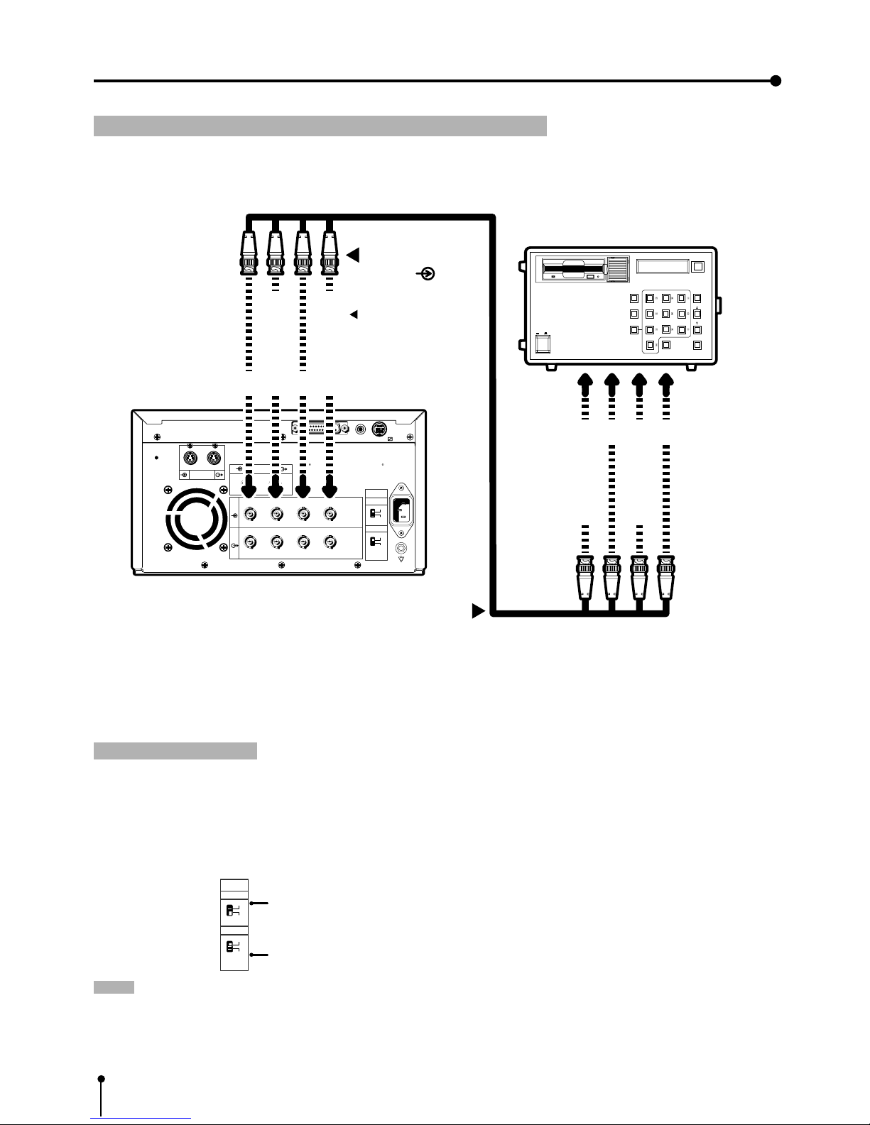
1 Connection with Monitors
Connect this unit with a monitor to check the images to be printed and the images stored in memory.
The following example shows the connection with a video signal, a S-video signal and RGB analog signal equipment.
Connect with the necessary signal equipment.
When connecting the unit with a monitor, make sure to set the power of each equipment to “OFF” .
To VIDEO OUT termi nal
VIDEO ( )
AC LINE
R G/G+SYNC B H+V-SYNC
R G/G+SYNC B H+V-SYNC
IN
OUT
S-VIDEO
VIDEO
75Ω
HIGH
75Ω
HIGH
IMPEDANCE
SYNC.
RGB
RS-232C
R
G/G+SYNC.
B
H+V-SYNC.
R
G/G+SYNC.
B
H+V-SYNC.
To S-VIDEO OUT terminal
S-VIDEO ( )
To S-VIDEO IN terminal
To RGB Analog OUT
terminals ( )
To RGB Analog IN
terminals
Monitor
VCP
To VIDEO IN terminal
REMOTE
12
15
4. Connection with external equipment (Monitor)
Setting the sync. polarity and output sync. signal
When the sync. polarity or sync. signal of a monitor to be connected is not adjusted to the initial setting of this unit, the image
may not be displayed correctly. In this case, adjust the sync. polarity and sync. signal output to the monitor.
When the image is displayed correctly, the setting is not required. (Refer to the operation manual of the monitor as for the sync.
polarity and sync. signal of the monitor.)
Displaying the menu
, The sync. polarity and sync. signal is set by the menu displayed on LCD.
, Make sure to turn off the power before setting.
Displaying “Memory SW Main Menu”
1 Press the POWER button while pressing the MEMORY button on the front
panel.
The menu for memory switch “Memory SW Main Menu” is displayed.
Displaying “Signal Adj Menu”
} Use the buttons on the remote control to display and set the items in this
menu.
2 Press the DOWN button to select “3. SIGNAL ADJUST : PUSH
[ ] ]” menu.
3 Press the RIGHT
button.
, The menu for signal setting, “Signal Adj Menu” is displayed.
, The sync. polarity, “SYNC” and output sync signals, “OUTPUT SYNC”
and “RGB SOG OUT” can be set in this menu.
Setting the sync. polarity “SYNC : NEGA POSI”
4 Press the UP or DOWN button to select “SYNC” .
, In the initial setting, “IN SYNC” is selected in “3.SIGNAL ADJ : PUSH
[ ] ]” . When other menu is selected, press the UP or DOWN
button to select “SYNC” .
The sync. polarity being selected, for example, “NEGA” is displayed.
Press the RIGHT or LEFT button to select “NEGA” or
“POSI” according to the polarity of the equipment to be connected.
Memory SW Main Menu
1.TIME ADJ :PUSH[>]
LCD
Memory SW Main Menu
3.SIGNAL ADJ:PUSH[>]
Signal Adj Menu
IN SYNC : TTL,SOG
Signal Adj Menu
SYNC : NEGA
16
4. Connection with external equipment (Monitor)
Setting the output sync. signal “OUTPUT SYNC”
5 Press the DOWN or UP button to select “OUT SYNC”.
, The set level of the sync. signal, for example, “0.3V” is displayed.
Set the sync. signal according to the equipment to be connected.
Press the RIGHT
or LEFT button to select “0.3V” or
“TTL”.
0.3V ...... 0.3Vp-p
TTL .... TTL level
Setting the output RGB Analog signal “RGB SOG OUT”
6 Press the DOWN or UP button to select “RGB SOG OUT”.
7 Press the RIGHT
or LEFT button to select “ON” or “OFF”.
OFF...... Outputs Composite Sync. signal
ON ...... Outputs Sync. On Green + Composite Sync. signal.
Select “ON” or “OFF” according to the monitor to be connected.
8 Press the SET
SET
button.
, “CHANGE : OK/CANCEL” is selected.
Press the RIGHT
or LEFT shift button to select “OK” or
“CANCEL” .
9 Select “OK” , then press the SET
SET
button.
, “Memory SW Main Menu” is displayed.
A Press the SET
SET
button.
, “CHANGE : OK” is selected.
B Select “OK” , then press the SET
SET
button.
, The source image (input signal from the equipment) is displayed.
0 The setting of the sync. polarity and signal is completed.
Signal Adj Menu
OUT SYNC:TTL
Signal Adj Menu
RGB SOG OUT:OFF
Signal Adj Menu
CHANGE : OK
Memory SW Main Menu
3.SIGNAL ADJ:PUSH[>]
17
4. Connection with external equipment (VIDEO/S-VIDEO)
AC LINE
R G/G+SYNC B H+V-SYNC
R G/G+SYNC B H+V-SYNC
IN
OUT
S-VIDEO
VIDEO
75Ω
HIGH
75Ω
HIGH
IMPEDANCE
SYNC.
RGB
RS-232C
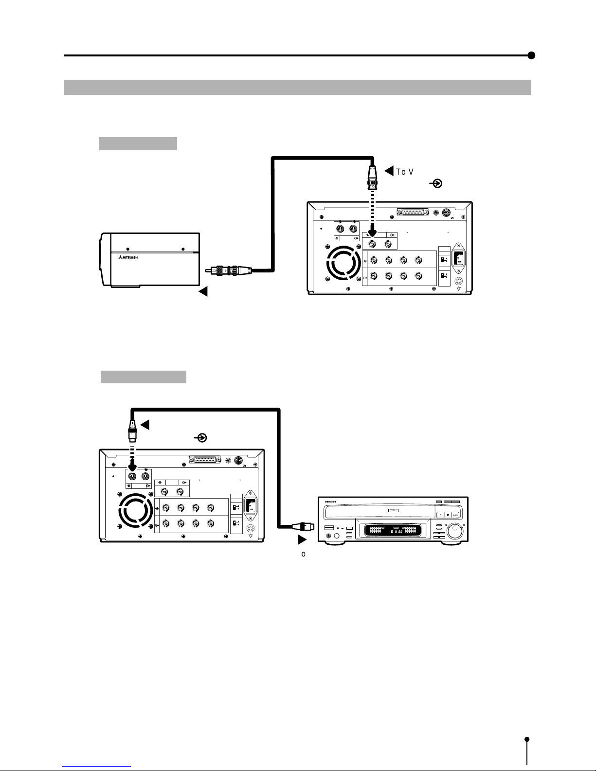
To VIDEO IN terminal
VIDEO ( )
To VIDEO OUT terminal
VCP
VIDEO signal
equipment
REMOTE
12
CCD COLOR VIDEO CAMERA CCD-200E
AC LINE
R G/G+SYNC B H+V-SYNC
R G/G+SYNC B H+V-SYNC
IN
OUT
S-VIDEO
REMOTE
VIDEO
75Ω
HIGH
75Ω
HIGH
IMPEDANCE
SYNC.
RGB
RS-232C
CONFORTABLE LD PLAYER DP-L2000
To S-VIDEO IN terminal
S-VIDEO ( )
To S-VIDEO OUT terminalVCP
S-VIDEO signal equipment
12
2
Connection with VIDEO signal, S-VIDEO (Y/C separate VIDEO) signal equipment
When connecting the unit with another equipment, make sure to set the power of each equipment to “OFF”.
VIDEO signal
S-VIDEO signal
18
4. Connection with external equipment (RGB Analog signal)
3 Connection with RGB Analog Signal equipment
, When connecting the unit with another equipment, make sure to set the power of each equipment to “OFF”.
, Use BNC type cable on the market for connection.
, This unit functions at 15.625 kHz for H and 50Hz for V.
Setting the switches
, Set the impedance switches “IMPEDANCE” on the rear panel to the impedance of the equipment connected.
Normally,
a.Set the RGB analog signal to “75Ω”.
b.Set the sync signal to “HIGH.
NOTE: • When the power turns off or the display is not appeared with analog through mode, the impedance switch is not
available. So, connect the unit with the side of monitor or external terminal .
• When connecting to a monitor, use the monitor with 75Ω.
75Ω
HIGH
75Ω
HIGH
IMPEDANCE
SYNC.
RGB
Impedance switch for RGB analog signal
Impedance switch for sync. signal
AC LINE
R G/G+SYNC B H+V-SYNC
R G/G+SYNC B H+V-SYNC
IN
OUT
S-VIDEO
VIDEO
75Ω
HIGH
75Ω
HIGH
IMPEDANCE
SYNC.
RGB
RS-232C
RECORD
REPLAY
10 KEY
RED
GREENGREEN
BLUEBLUE
CONTRAST
BRIGHTNESSBRIGHTNESS
SCAN SPEED
RESETRESET
WHITE
BALANCE
SCAN START
POWER
ON OFF
R
G/G+SYNC.
B
H+V-SYNC.
To RGB Analog OUT terminal
R
G/G+SYNC.
B
H+V-SYNC.
To RGB Analog IN
terminal ( )
VCP
RGB Analog signal equipment
In case of SYNC ON G.
signal, it is not
necessary to connect to
the unit.
REMOTE
12
19
4. Connection with external equipment (RS-232C Interface)
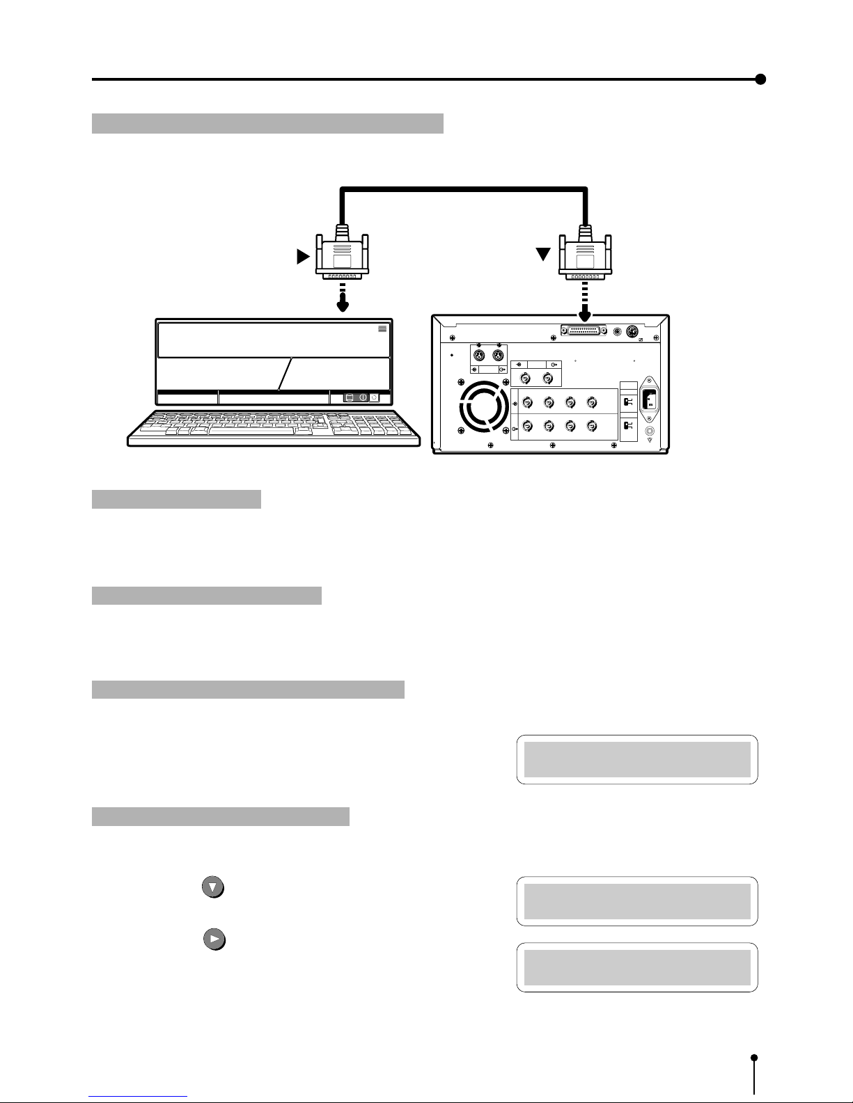
4 Connection with RS-232C equipment
, When connecting the unit with another equipment, make sure to set the power of each equipment to “OFF”.
Setting BAUD RATE
Set the baud rate of this unit according to the equipment to be connected.
, As to the baud rate of the equipment connected, refer to the operation manual of the equipment connected.
Displaying the menu screen
,
The baud rate is set on the menu displayed on the monitor screen or LCD. (The following is an example of display on LCD.)
, Make sure to turn off the power before setting.
Displaying “Memory SW Main Menu”
1 Press the POWER button while pressing the MEMORY button on the
front panel.
, The menu for memory switch, “Memory SW Main Menu” is displayed.
Displaying “System Set Menu”
} Use the buttons on the remote control to display and set this menu.
2 Press the DOWN button to select “5. SYSTEM SET : PUSH
[ ] ]” .
3 Press the RIGHT button.
, The menu for signal setting, “System Set Menu” is displayed.
, Set “BAUD RATE” on this menu.
Memory SW Main Menu
1.TIME ADJ :PUSH[>]
Memory SW Main Menu
5.SYSTEM SET:PUSH[>]
System Set Menu
PRG ALL INIT : OFF
AC LINE
R G/G+SYNC B H+V-SYNC
R G/G+SYNC B H+V-SYNC
IN
OUT
S-VIDEO
VIDEO
75Ω
HIGH
75Ω
HIGH
IMPEDANCE
SYNC.
RGB
RS-232C
To RS-232C port
(RS-232C)
To RS-232C port
VCP
Equipment with RS-232C
REMOTE
12
20
4. Connection with external equipment (RS-232C Interface)
Setting BAUD RATE
1 Press the DOWN or UP shift buttons to select “BAUD RATE”.
The set baud rate, for example, “9600” , is displayed.
Press the RIGHT or LEFT SHIFT button to select “1200” ,
“2400” , “4800” or “9600” Bit/Sec) .
2 Press the SET
SET
button.
, “CHANGE : OK” is selected.
, Press the RIGHT
or LEFT shift button to select “OK” or
“CANCEL” .
3 Select “OK” , then, press the SET
SET
button.
, “Memory SW Main Menu” is displayed.
4 Press the SET
SET
button.
, “CHANGE : OK” is selected.
5 Select “OK”, then, press the SET
SET
button.
, The source image (input signal from the equipment connected) is displayed.
0 The setting of BAUD RATE is completed.
System Set Menu
BAUD RATE : 9600
System Set Menu
CHANGE : OK
Memory SW Main Menu
5.SYSTEM SET:PUSH[>]
System Set Menu
COMMAND TYPE : A
System Set Menu
CHANGE : OK
Memory SW Main Menu
5.SYSTEM SET:PUSH[>]
Setting the RS-232C COMMAND TYPE
Select “A” or “B” according to the equipment connected.
1 Press the DOWN or UP buttons to select “COMMAND TYPE” .
Press the RIGHT
or LEFT SHIFT button to select “A” or “B”.
2 Press the SET
SET
button.
, “CHANGE : OK” is selected.
, Press the RIGHT or LEFT button to select “OK” or
“CANCEL” .
3 Select “OK” , then, press the SET
SET
button.
, “Memory SW Main Menu” is displayed.
21
4. Connection with external equipment (RS-232C Interface)
4 Press the SET
SET
button.
, “CHANGE : OK” is selected.
5 Select “OK”, then, press the SET
SET
button.
, The source image (input signal from the equipment connected) is displayed.
0 The setting of COMMAND TYPE is completed.
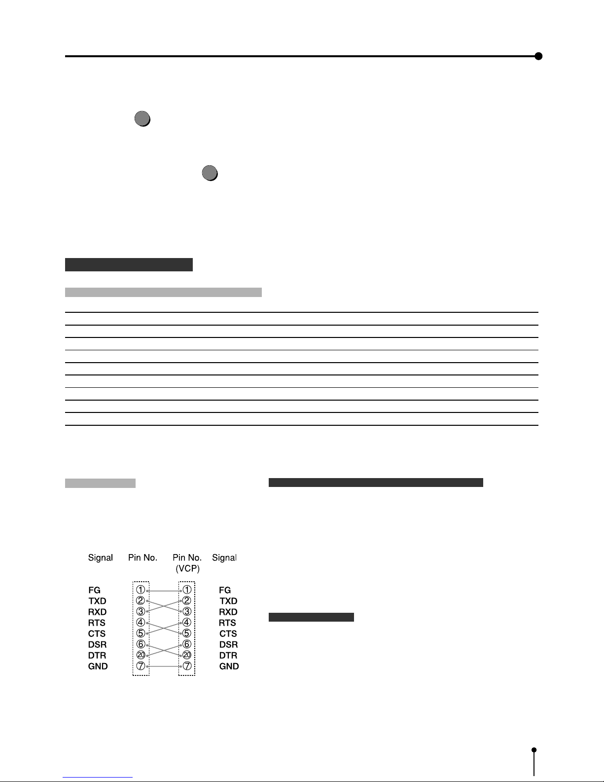
RS-232C DATA SIGNAL
RS-232C input connector port signal allocation
Pin No. Signal line name Description Directions (From VCP side)
1 F G Protective - -2 TX D Transmitted data Output
3 R X D Received data Input
4 RTS Request to send Output
5 CT S Clear to send Input
6 D S R Data set ready Input
7 G N D Signal ground --20 D T R Data terminal ready Output
Setting the communication format of the computer
, Set the communication format as follows:
(1) Synchronizing system Asynchronous communication
(2) Data bit length 8 bits
(3) Parity bit Nothing
(4) STOP bit length 1
(5) Transmission order Sent from LSB
(6) Baud rate (Bit / Sec) 1200, 2400, 4800, 9600
RS-232C function
, This unit can be controlled through RS-232C terminal.
( The input of image data is not possible.)
Consult with the sales dealer for the details of controlling
method (protocol).
Pin connection
, Connect the unit with the host computer
through cross-over cable.
Cross-over cable
22
5. Features and functions
1 FRONT PANEL pages 22 - 23
Explains the buttons and terminals, etc. on the front panel.
2 INSIDE OF PRINTING UNIT page 23
Explains the installation of the ink cassette, print paper and battery inside the unit.
3 REAR PANEL page 24
Explains input/output terminals on the rear panel.
4 REMOTE CONTROL pages 25 - 26
Explains the functions of the buttons on the remote control.
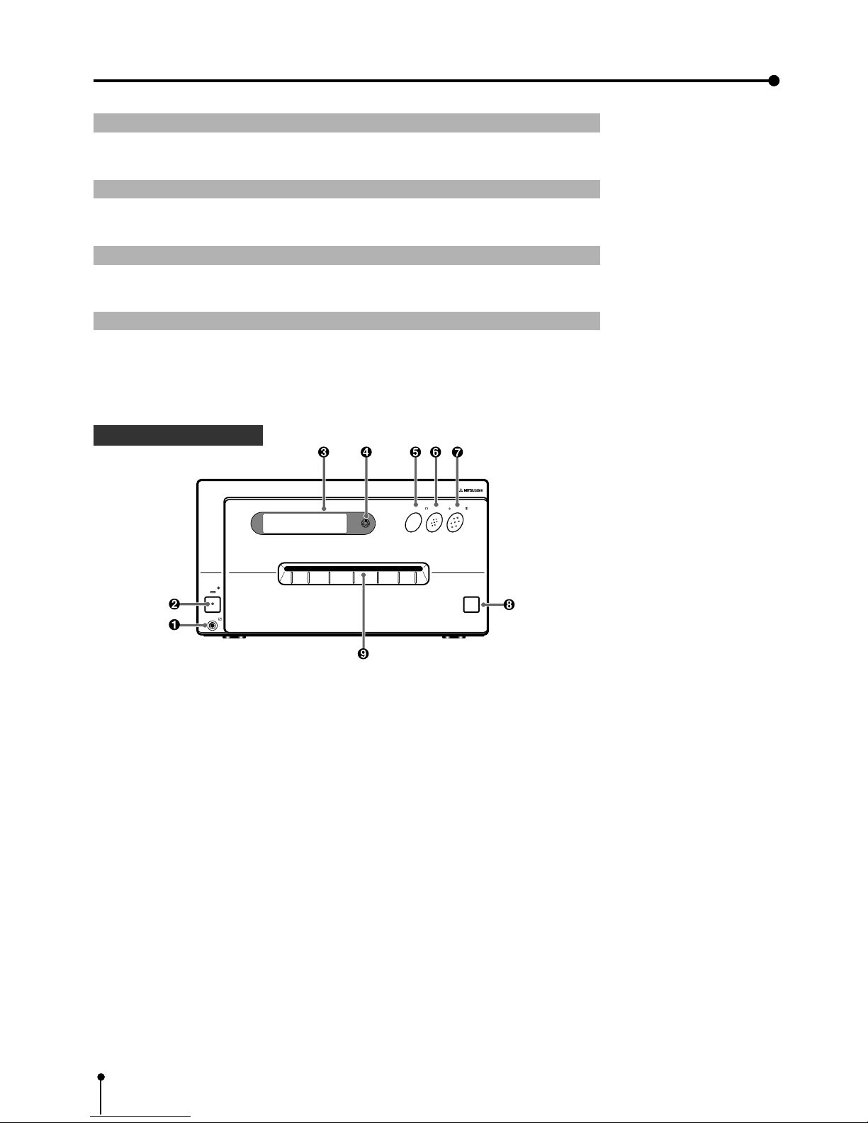
1 FRONT PANEL
1 Remote terminal [REMOTE]
Connect the remote control of the printer in this terminal.
The remote control cannot be worked when connecting to the “REMOTE 1” terminal on the rear panel.
2 Power button [POWER]
Press this button to turn on and off the power. When power is turned on, the indicator lights up.
3 LCD display
Displays the set conditions of the input signal, and used to set various functions.
(The menus displayed on the monitor or LCD are used to set various settings.Refer to pages 37 - 64. )
4 LCD contrast control [LCD CONTRAST]
Adjusts the contrast of the LCD. Turn this control by pressing with a finger. Set the contrast so that you can see the
displayed characters easily.
5 Monitor button [MONITOR]
Switches the display on the monitor. When this button is pressed, the picture on the monitor screen switches between the
picture of the input signal (source image) and the memorized image.
OPEN
MEMORY
PRINT
POWER
REMOTE
MEMORY
PRINT
MONITOR
23
5. Features and Functions
6 Memory button [MEMORY]
This enables memorization of the image to be printed.
7 Print button [PRINT]
Press this button to print the images memorized by the MEMORY button. A green lamp will light during printing. The screen
switches to the picture of the input signal.
8 Open button [OPEN]
When this button is pressed, the printing unit will slide out. The printing unit is used when loading ink cassette and
printing paper or overcoming paper jams.
9 Print outlet
The printed paper come out here.
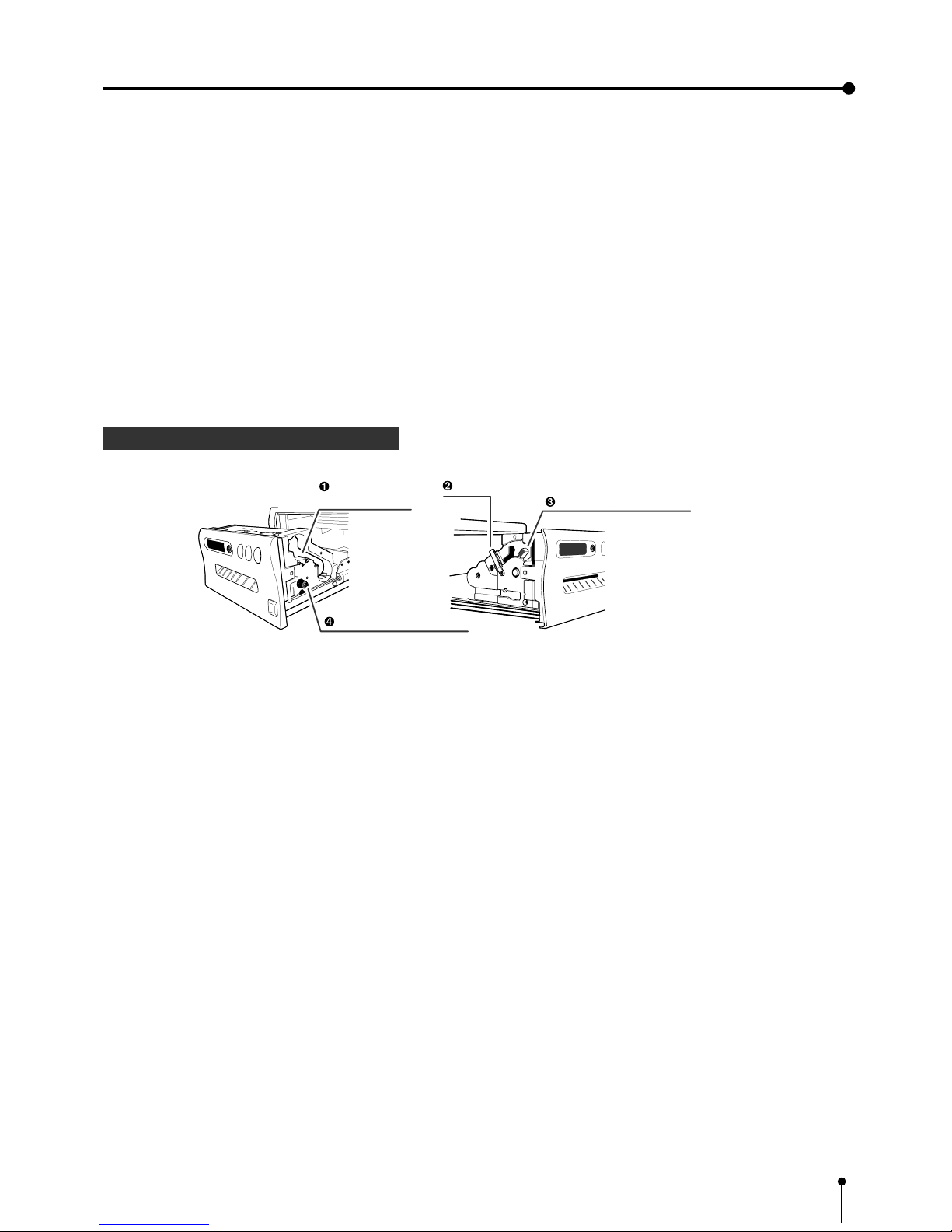
2 INSIDE OF PRINTING UNIT
1 Ink cassette compartment
Load the cassette with ink sheet.
2 Ink cassette locking lever
Push this lever to take the ink cassette out.
3 Print paper fixing lever
Use this lever when inserting print paper.
4 Paper sending control
Turn this control clockwise to rewind the print paper .
Ink cassette
compartment
Ink cassette locking lever
Print paper fixing lever
Paper sending control
24
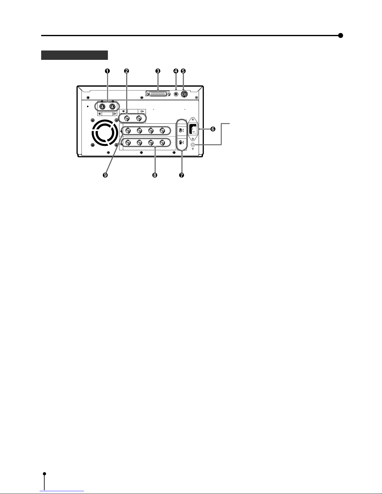
5. Features and Functions
1 S-VIDEO SIGNAL INPUT/OUTPUT TERMINALS [S-VIDEO]
Use these terminals to connect this unit to S-VIDEO signal equipment.
Refer to page 17 for connection.
2 VIDEO INPUT/OUTPUT TERMINALS [VIDEO]
Use these terminals to connect this unit to VIDEO signal equipment.
Refer to page 17 for connection.
3 RS-232C PORT [RS-232C]
Use this terminal to connect this unit to a device equipped with RS-232C interface.
Refer to pages 19 - 21 for connection.
4 EXTERNAL REMOTE TERMINAL [REMOTE 1]
Memorizing images are available by the remote signal inputted through this terminal. It is necessary to make a circuit for
remote control to use the function.
Refer to page 83.
5 EXTERNAL REMOTE TERMINAL [REMOTE 2]
Memorizing images and printing are available by the remote signal inputted through this terminal. It is necessary to make a
circuit for remote control to use the function.
Refer to pages 81 - 83.
6 POWER SOCKET [AC LINE]
This socket connects to the power cord (accessory).
Insert the cord firmly.
7 IMPEDANCE SELECTION SWITCH [IMPEDANCE RGB, SYNC. ]
This is a 75Ω / HIGH impedance selection switch for RGB or Sync. signal.
8 RGB ANALOG OUTPUT TERMINALS [R,G/G+SYNC, G,H+V-SYNC]
This is a BNC type output terminal for a RGB analog signal. Sync. signal can be selected between 0.3V(H+V-SYNC.) and
TTL(H+V-SYNC.) signals.
Refer to page 18 for connection.
9 RGB ANALOG INPUT TERMINALS [R,G/G+SYNC , B,H+V-SYNC ]
This is a BNC type input terminal for a RGB analog signal. The sync. signal can be automatically selected between H/V
composite and SYNC. ON GREEN (sync. signal imposed on the green video signal) signals. Refer to page 18 for switch
setting.
3 REAR PANEL
R G/G+SYNC B H+V-SYNC
R G/G+SYNC B H+V-SYNC
IN
OUT
S-VIDEO
REMOTE
AC LINE
VIDEO
75Ω
HIGH
75Ω
HIGH
IMPEDANCE
SYNC.
RGB
RS-232C
12
Potential equalization connector
This is used to equalize the potential of the equipment
connected to the unit.
For details, refer to the installation instruction of the
equipment to be connected.

25
5. Features and Functions
1 COLOR IMAGE ADJUSTMENT button [COLOR ADJUST]
When this button is pressed, a screen for adjusting the video image is displayed. Use this button to set the various functions
of this unit. (The menus displayed on the monitor or LCD is used to set the various settings. Refer to Pages 45 - 46.)
2 FIELD/FRAME button [FIELD / FRAME]
Press this button to switch the input signal between the FRAME or FIELD mode.
Every time this button is pressed, the mode is switched in the order of “FIELD”, “FRAME” and “FIELD”.
3 DISPLAY button [DISPLAY]
When this button is pressed, the set conditions are displayed on the monitor screen. Press it again so that the display is not
shown.
4 PRINT QUANTITY button [PRINT Q'ty]
This button is used to set the number of prints. Press
button to increase the number and button to decrease.
5 SET button [SET]
Use this button to set the various functions of this unit. For example, use it to fix the setting and return to the normal display from
the menu screen. (The menus displayed on the monitor or LCD is used to set the various settings. Refer to pages 42 - 43.)
6 STOP button [STOP]
Press this button and the button to the left side of STOP button at the same time to cancel the printing process. The image
is printed out in the state when the printing was cancelled.
7 MEMORY PAGE button [MEMORY PAGE]
This button is used to select the image memorized by the MEMORY button. Every time this button is pressed, the memory
page is switched.
4 REMOTE CONTROL
PROG.
MENU
CLEAR
MONITOR
MEMORY
MEMORY
PAGE
STOP
SET
COLOR FIELD
ADJUST /FRAME
DISPLAY
PRINT
Q' ty
-
+
PRINT

26
5. Features and Functions
8 PRINT button [PRINT]
Press this button to print the image memorized by the MEMORY button. The image on the monitor screen is switched to the
picture of the input signal.
9 PROGRAM button [PROG.]
Press this button to select the images memorized in the program of this unit and various settings such as printing.
Each time this button is pressed, the program is switched. This unit has 3 kind of programs and they can be changed and
stored voluntarily.
Programs cannot be changed during printing.
A SHIFT buttons
These buttons are used to change settings, such as selecting a function and moving to the next menu. (The menus displayed
on the monitor or LCD is used to set the various settings. Refer to pages 42 - 43.)
B MENU button [MENU]
Press this button to display the main menu.
This button is used to set the various settings.(The menus displayed on the monitor or LCD is used to set the various
settings. Refer to pages 42 - 43.)
C CLEAR button [CLEAR]
Press this button and the right side button at the same time to eliminate all or a part of memorized images.
D MONITOR button [MONITOR]
When this button is pressed, the picture on the monitor screen switches between the picture of the input signal and the
memorized image.
E MEMORY button [MEMORY]
This enables memorization of the image to be printed.

27
6. Printing procedures (Basic prints)
1 Printing Pages 28 - 34
Explains storing an image in the memory and printing
2 Continuous printing Pages 35 - 36
Explains the continuous printing of the same image.
{ S size printing
{ L size printing
One picture image can be printed on one sheet.
 Loading...