

Page 1
LEVEL 2 SERVICE
FA9M0475
COSMO (DUAL BAND)
R V A : Création D.JUET 04/00 Rédigé par Verifié par Approuvé par
E E B : Ajout Assy-Desassy 3c 08/00
V R C : Passage à IPL2000 10/00
I S
S I
I O
O N
N S
S
Mitsubishi Electric Telecom Europe S.A. Version C
ZA le Piquet, 35370 Etrelles Date: 10/00
Phone: +33 2 99 75 71 00
Fax: +33 2 99 75 71 47
Written by Checked by Approuved by
X. GLASSON BT LEGORGEU G. LEBASTARD
Page 2
Level 2 Service Manual
COSMO
Version C Mitsubishi Electric Telecom Europe S.A.
Date: 10/00 ZA le Piquet, 35370 Etrelles
Phone: +33 2 99 75 71 00
Fax: +33 2 99 75 71 47
Page 3
Level 2 Service Manual
COSMO
TABLE OF CONTENTS
1. GENERAL DESCRIPTION...................................................................................................................1
2. MAIN FEATURES OF TRANSCEIVER ..............................................................................................2
2.A DESCRIPTION OF TRANSCEIVER ...........................................................................................................2
2.B IMEI LABEL....................................................................................................................................... 3
2.C ART LABEL.......................................................................................................................................3
2.D SIM LATCHING.................................................................................................................................. 4
3. EXPLODED DIAGRAM AND SPARE PART LIST ............................................................................5
3.A EXPLODED DIAGRAM OF COSMO.......................................................................................................5
3.B SPARE PART LIST OF COSMO.............................................................................................................. 6
3.C ASSEMBLY AND DESASSEMBLY INSTRUCTION....................................................................................... 7
4. TEST AND MEASUREMENTS............................................................................................................. 9
4.A E-GSM / DCS MEASUREMENTS.......................................................................................................... 9
4.a.1 Transmitter Power and Ramp profile............................................................................................. 9
4.a.2 Phase / Frequency / Time relationship........................................................................................... 9
4.a.3 Receiver Bit Error Rate (RX sensitivity) ........................................................................................ 9
4.a.4 Handover between E-GSM 900 & DCS 1800 standards................................................................. 9
4.B OPERATING INSTRUCTIONS ............................................................................................................... 10
4.C BUZZER AND SPEAKER TESTS ............................................................................................................ 11
5. SERVICE SOFTWARES ..................................................................................................................... 12
5.A SOFTWARE DOWNLOAD WITH IPL2000.............................................................................................. 12
5.a.1 How to install IPL2000 software and equipment.......................................................................... 12
5.a.2 Software description.................................................................................................................... 13
Start download........................................................................................................................................ 14
5.a.4 End of Download......................................................................................................................... 15
5.B SETTINGS DOWNLOAD WITH MS TOOLS ............................................................................................ 16
5.b.1 How to install MS Tools software and equipment..................................................................... 16
5.b.2 Software description................................................................................................................ 17
5.b.3 Start download ........................................................................................................................ 17
5.b.4 End of download ...................................................................................................................... 18
5.b.5 How to print labels using MS Tools ......................................................................................... 19
5.b.6 Print labels.............................................................................................................................. 20
6. SOFTWARE AND SETTING VERSION............................................................................................ 21
7. OPERATOR DEBUGGING ................................................................................................................. 21
Mitsubishi Electric Telecom Europe S.A. Version C
ZA le Piquet, 35370 Etrelles Date: 10/00
Phone: +33 2 99 75 71 00
Fax: +33 2 99 75 71 47
Page 4

Page 5
Level 2 Service Manual
COSMO
1. GENERAL DESCRIPTION
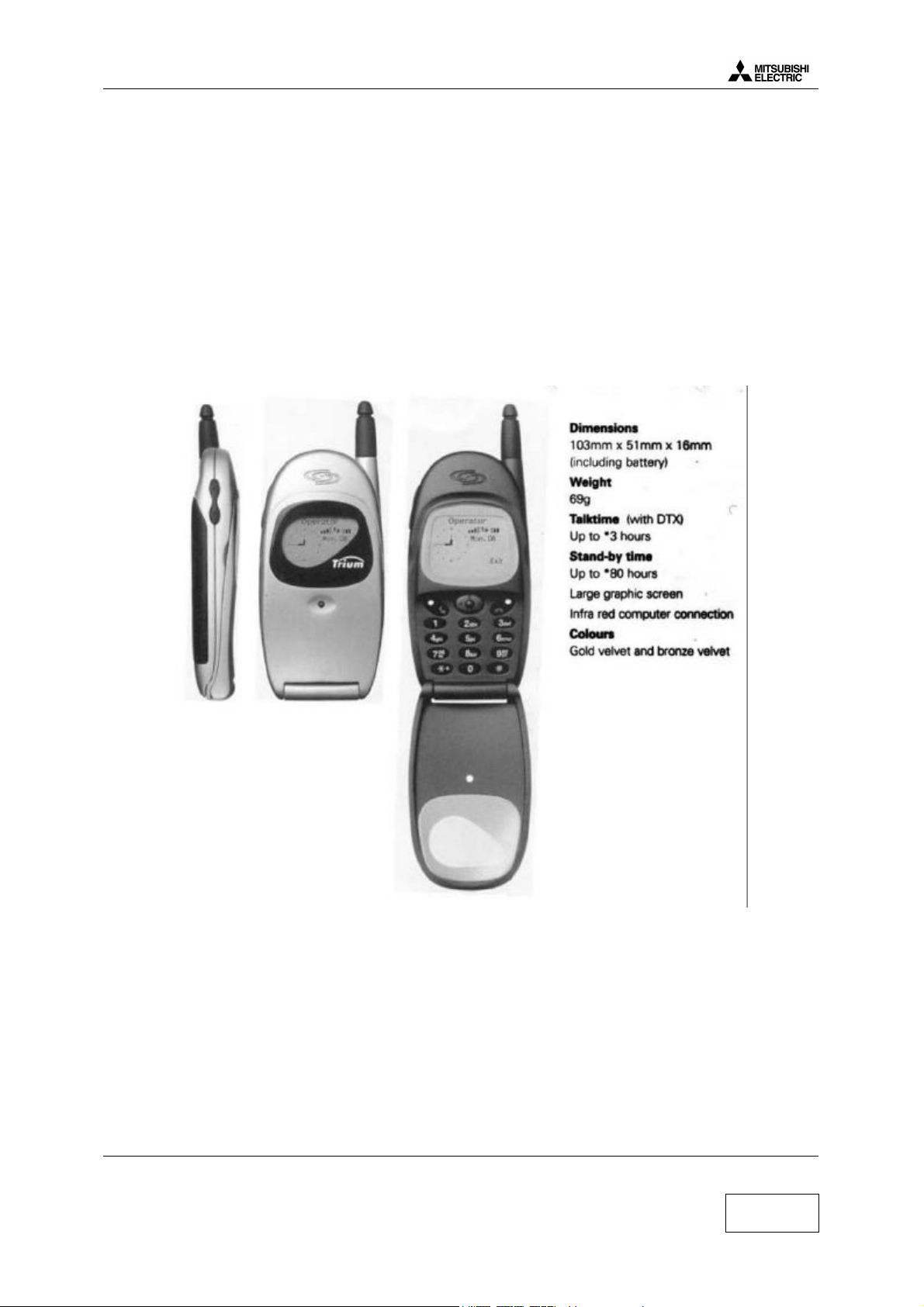
Cosmo is designed for use with E-GSM/DCS network. This phone operates and complies with the ETSI GSM
Phase 2 specifications.
Standard kit includes following items :
• Tranceiver (retractable antenna type)
• Battery pack (3.8 V 540 mA Li-Ion)
Reference : FZA-0052A
• AC/DC adapter for battery rapid charging (6.5 V 400 mA)
Reference : 2PS304/00
Speech codec :
COSMO uses a speech codec which is able to switch from half rate (HR) to full rate (FR) or to
enhanced full rate (EFR) according to network and the software & settings version.
Enhanced full rate (EFR) allows better voice quality at same rate as full rate.
Half rate (HR) is coding on 5.6 kbits/s (1/2 full rate) the network may put two customers on one time
slot. each customer will use this timeslot every two frames.
Mitsubishi Electric Telecom Europe S.A. Version C
ZA le Piquet, 35370 Etrelles Date: 10/00
Phone: +33 2 99 75 71 00
Fax: +33 2 99 75 71 47
1/20
Page 6
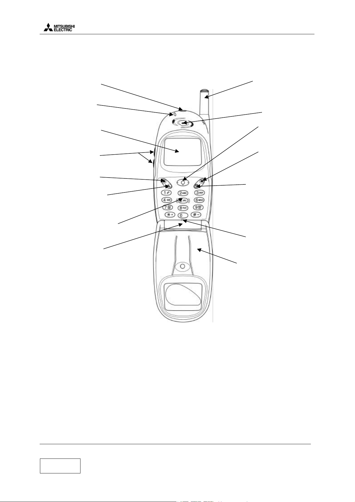
2. MAIN FEATURES OF TRANSCEIVER
2.a Description of transceiver
Level 2 Service Manual
COSMO
Infrared
module
LED:
call & battery
charge indicator
Graphic Display: telephone
numbers, menus, messages,etc
are displayed here
Volume keys
Left softkey
(programmable)
Call/Send Key:
number or name and answers
calls
Alphanumeric Keys:
to enter text and telephone
numbers
AC/DC
Charger, accessories and
headset socket
dials displayed
Retractable Antenna:
extend the antenna fully
when making or
receiving a call
Earpieces
Joystick:
navigates around
the memories and
menus
Right Softkey:
(programmable)
On/Off,End Key:
hold down to turn on or
off the phone. Press to
end a call or return to
standby display
Microphone
Flip:
open when you want to
use the alphanumeric
keys
NB : opening or closing
the flip does not answer
or end a call
For M4 family, to make test is not possible directly from mobile. This is possible only using a PC and the
relevant software .
Version C Mitsubishi Electric Telecom Europe S.A.
Date: 10/00 ZA le Piquet, 35370 Etrelles
Phone: +33 2 99 75 71 00
2/20
Fax: +33 2 99 75 71 47
Page 7
Level 2 Service Manual
COSMO
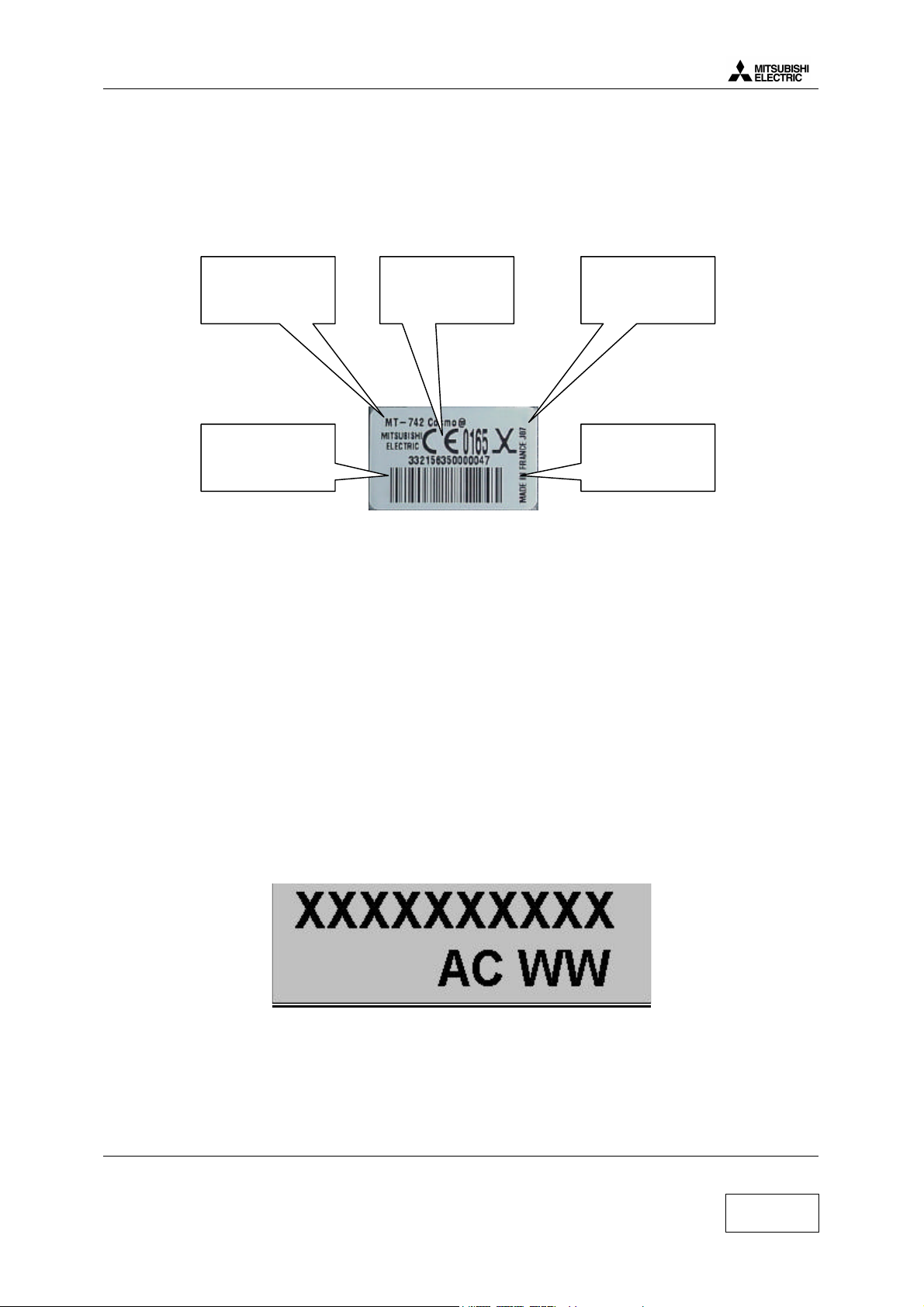
2.b IMEI label
IMEI label stands for International Mobile Equipment Identity. The IMEI label is stuck on the rear case of the
terminal. It is held in the logic circuit of the main board itself. If the main board is changed then IMEI will
change.
Date Code is made of 3 digits and indicates the date of shipment from factory.
For example, in J07, J stands for 2000 and 07 for July (12 for december).
Bar code indicates 15 digits 123456 45 456789 4 (for example) of the IMEI written in plain letters above the
bar code:
- 123456 : The 6 first digits indicate the Type Approval Code (different according to type of mobile).
- 45 : These 2 digits are allocated to production site.
- 456789 : The 6 last digits are a sequential number (different for each mobile).
- 4 : Check digit.
Kit designation Date code
IMEI number
and bar code
Logo Norme
Europe
Made in France
Information
2.c ART Label
The Label Art Plate identifies the type of assembly , board version of the mobile
.
XXXXXXXXXX : 10 characters for the article code of the terminal.
A : 1 character for the assembly version of M/U.
C : 1 character for the board version.
WW : 2 characters related to production site.
Mitsubishi Electric Telecom Europe S.A. Version C
ZA le Piquet, 35370 Etrelles Date: 10/00
Phone: +33 2 99 75 71 00
Fax: +33 2 99 75 71 47
3/20
Page 8

Level 2 Service Manual
COSMO
2.d SIM Latching
SIM Lock consists in restricting the use of the terminal to a family of SIM cards. For the SIM Lock, three sets
of information are used. This information is read from data fields in the SIM card.
1°) IMSI (International Mobile Subscriber Identity), 15 Digits :
Example of IMSI : 208 01 55 12312312
208 = MCC = Mobile Country Code (ex : 208 for France)
01 = MNC = Network Country Code (ex : 01 for FT)
55 = NS = Network Subset
12312312 = serial number
2°) Group IDentifier 1 (GID1):
This data field can contain digits or letters which identify a family of SIM
Ex : XX for a type for of prepaid SIM card of Service provider Y
3°) Group IDentifier 2 (GID2) :
Same as GID1 to identify a sub family of SIM.
Then, from this information, we have 5 types of latch :
1°) Network Level :
Latch on MCC MNC of IMSI of the SIM only
(ex : only the cards 208 01 are able to operate the mobile.
Mitsubishi calls this latch NCK (NCK stands for “ Network Control Keys” and is the password to lock
the mobile at the network level)
2°) Network Subset Level :
Latch on MCC, MNC and digit 6 and 7 of the IMSI
Ex : latch on 208 01 55, only the SIM cards with an IMSI starting with 208 01 55 will operate the
mobile.
Mitsubishi calls this latch NSCK (“Network Subset Control Key”)
3°) Service provider level :
Latch on Network (value of MCC MNC) and value of GID1 data field.
Ex : latch on the value “XX” in GID1 and MCC MNC=208 01, only the SIM cards of service provider
Y with XX stored in data field GID1 will operate the mobile.
Mitsubishi calls this latch SPCK (Service Provider Control Key)
4°) Corporate Provider Level :
Latch on network (value of MCC and MNC) and a value stored in GID2
Mitsubishi calls this latch CPCK (Corporate Provider Control Key)
5°) IMSI level:
Latch on the complete IMSI of one SIM card.
Only one SIM card corresponding to the correct IMSI operates the mobile. Usually, this latch is done
automatic (the first SIM card inserted in the mobile is the only SIM which can be used by this
mobile).
General information :
To lock /unlock a mobile, you need an 8 digit password for each level concerned, and each mobile (one
set of passwords for one IMEI). These passwords are calculated with a special algorithm. You have
only 10 attempts to unlock a mobile. After 10 unsuccessful attempt, the mobile is permanently blocked.
To enter the unlock procedure, you need to access special menus with specific access codes.
Version C Mitsubishi Electric Telecom Europe S.A.
Date: 10/00 ZA le Piquet, 35370 Etrelles
4/20
Phone: +33 2 99 75 71 00
Fax: +33 2 99 75 71 47
Page 9

Level 2 Service Manual
COSMO
3. EXPLODED DIAGRAM AND SPARE PART LIST
3.a Exploded Diagram of COSMO
10
13
19
15
06
14
01
16
09
17
11
08
07
03
02
03
05
05
12
Mitsubishi Electric Telecom Europe S.A. Version C
ZA le Piquet, 35370 Etrelles Date: 10/00
Phone: +33 2 99 75 71 00
Fax: +33 2 99 75 71 47
5/20
Page 10

Level 2 Service Manual
3.b Spare part list of COSMO
Position Designation Reference
01 PCA BOARD FZ12120230
02 I/O CONNECTOR FK6T000610
03 MICROPHONE GROMMET FK1R000313
04 MICRO 3V FK8L014211
05 REAR – SUB – ASSY CHAMPAGNE FK1N001911
05 REAR – SUB – ASSY BRONZE FK1N002021
05 REAR – SUB – ASSY SILVER FS13094530
06 LCD MODULE ASSY FK8L014113
07 METAL DOME M4 CO FK1Y000112
08 NAVIGATOR BUTTON FK1K000211
09 HINGES Included into Cover
10 FRONT – SUB – ASSY CHAMPAGNE FK1N001511
10 FRONT – SUB – ASSY BRONZE FK1N001621
10 FRONT – SUB – ASSY SILVER FS13094630
11 KEYPAD FK1K000111
12 SCREWS FK1B000210
13 FLIP CHAMPAGNE FK8L013911
13 FLIP BRONZE FK8L014011
13 FLIP SILVER FS13094430
14 CUSHION BUZZER FS2D013112
15 SPEAKER FK1R000712
16 ANTENNA FK8L014311
17 CUSHION L.C.D. Included into Cover
18 CAP RF FK1R000213
19 KEY VOL
COSMO
Connectors of COSMO
Position Designation Reference
J103 CONNECTOR I/O M4 CO FK6T000610
J101 & J102 BATTERY CONNECTOR FK6T000411
J201 GLOBAL L.C.D.CONNECTOR Included in LCD
J301 SIM CONNECTOR FK6T000910
J302 EARPIECE CONNECTOR Included in Earpiece
J400 RF CONNECTOR FK6T000510
Version C Mitsubishi Electric Telecom Europe S.A.
Date: 10/00 ZA le Piquet, 35370 Etrelles
Phone: +33 2 99 75 71 00
6/20
Fax: +33 2 99 75 71 47
Page 11

Level 2 Service Manual
COSMO
3.c Assembly and desassembly instruction
Desassembly :
Step Planning Work Article Qty
1 Remove the flip Part 19 1
2 Remove the RF cap Part 18 1
3 Unscrew and remove the antenna Part 17 1
4 Unscrew the mobile (from a to f) Parts 16 6
5 Open the mobile by pressing on the cover side near the ON/OFF key Parts 1 & 15 1
6 Remove the keypad and the receiver from the cover Parts 13 & 14 1
7 Unscrew and remove the LCD module Parts 9 & 10 1
8 Unscrew and remove the PCA Parts 2 & 7 1
9 Remove the navigator button and the cushion buzzer from the PCA Parts 8 & 11
10 Remove the I/O connector from the PCA Part 6 1
11 Remove the Mic Assy from the I/O connector Part 5 1
12 Remove the Mic from the Holder Mic Part 4 1
13 Unstick the 2 bottom spacers using a twiser Part 12 1
14 Unstick the metaldome from the PCA using a twiser Part 3 1
Assembly :
Step Planning Work Article Qty
1 Stick the metaldome on the PCA Parts 2 & 3 1
2 Insert the navigator button Part 11 1
3 Insert the mic into the holder mic Parts 4 & 5 1
4 Insert the mic assy into the I/O connector Part 6 1
5 Insert the I/O connector on the PCA Part 6 1
6 Insert the cushion buzzer on the buzzer on the the PCA Part 8 1
7 Place the PCA into the case and screw (1.4 N.m) Parts 1 & 7 1
8 Place LCD module on the PCA ans screw (1.4 N.m) Parts 9 & 10 1
9 Stick the 2 bottoms spacers on the PCA Parts 12 2
10 Insert the receiver into the cover Part 14 1
11 Insert the keypad into the cover Part 13 1
12 Blow on the LCD, then assemble the case assy on the cover assy by
rock softy (key vol side to antenna side)
13 Screw the 6 screws (order : a to f at 1.4 N.m) Parts 16 6
14 Insert and screw the antenna Part 17 1
15 Insert the RF cap Part 18 1
16 Insert the flip Part 19 1
Mitsubishi Electric Telecom Europe S.A. Version C
ZA le Piquet, 35370 Etrelles Date: 10/00
Phone: +33 2 99 75 71 00
Fax: +33 2 99 75 71 47
7/20
Page 12

Level 2 Service Manual
COSMO
Version C Mitsubishi Electric Telecom Europe S.A.
Date: 10/00 ZA le Piquet, 35370 Etrelles
8/20
Phone: +33 2 99 75 71 00
Fax: +33 2 99 75 71 47
Page 13
Level 2 Service Manual
COSMO
4. TEST AND MEASUREMENTS
4.a E-GSM / DCS measurements
4.a.1 Transmitter Power and Ramp profile
These two are interrelated, since the power ramp shape and its final peak value stored in Serial FLASH as
adjustment values.
The peak power output must lie within 3 dB of specification and be flat to within 0.5 dB over the active period.
The ramp profile is designed to give minimum harmonics, and hence it is important to ensure its adherence.
Power ramp profile must be checked on all frequencies (in practice channels 975, 37 and 124 for the 900 MHz
band and channels 512, 698 and 885 for the 1800 MHz band). In conclusion, the ramp must fit with the mask
at all frequencies and all power levels. The mask is usually stored in the radiocommunication tester. The test
will also be available to cover the frequency and power range automatically.
4.a.2 Phase / Frequency / Time relationship
This is a test for the quality of the modulation including the IQ balance and the Gaussian filters. The phase of
the carrier changes according to the arrival of 1s and 0s. Phase error mustbe less than 20° peak and 5° RMS.
4.a.3 Receiver Bit Error Rate (RX sensitivity)
The specification is a Bit Error Rate (BER) of better than 2.44% for an input signal : -102 dBm for the E-GSM
900 band, and –100 dBm for the DCS 1800 band. There should be no error for -90 dBm to -20 dBm input
signal. The maximum workable error rate is 13%.
It is important that BER and RX sensitivity are good since measures of RXLEV (from -103 to -41 dBm) and
RXQUAL (from 0 to 7) are reported back to the base station on the SACCH to assist in handovers and power
level control. Errors in reporting will lead to sub optimum use of channel space, or interference to others.
4.a.4 Handover between E-GSM 900 & DCS 1800 standards
The M4 dual band may handover from the E-GSM 900 band to the DCS 1800 band automatically. If the
subscribed network (defined in setting) has frequencies in both bands, the M4 dual band will work either in
900 MHz or 1800 MHz band depending on the availability of frequencies.
Mitsubishi Electric Telecom Europe S.A. Version C
ZA le Piquet, 35370 Etrelles Date: 10/00
Phone: +33 2 99 75 71 00
Fax: +33 2 99 75 71 47
9/20
Page 14

4.b Operating instructions
RADIOCOMMUNICATION TESTER
RF Cable NN 50 OHMS 0.8
(FT7Y005610)
NSMA ADAPTATOR FEMALE
(FT7Y010010)
Level 2 Service Manual
Mobile with full
battery
CABLE RF M4 COSMO / SAV
FT0F000310
COSMO
1. Insert Test SIM in the mobile
2. Connect a charged battery
3. Make a call with a RADIOCOMMUNICATION TESTER and check the following parameters,
or use the autotest (CMD55 or CMD55 under MTS or Wavetek 4107)
Power levels : check the transmitted power (dBm)
E-GSM 900
PCL
Power Level
(dBm)
tolerance DCS 1800
PCL
Power level
(dBm)
tolerance
5 33 +/-2dB 0 30 +/-2dB
6 31 +/-3dB 1 28 +/-3dB
7 29 +/-3dB 2 26 +/-3dB
8 27 +/-3dB 3 24 +/-3dB
9 25 +/-3dB 4 22 +/-3dB
10 23 +/-3dB 5 20 +/-3dB
11 21 +/-3dB 6 18 +/-3dB
12 19 +/-3dB 7 16 +/-3dB
13 17 +/-3dB 8 14 +/-3dB
14 15 +/-3dB 9 12 +/-4dB
15 13 +/-3dB 10 10 +/-4dB
16 11 +/-5dB 11 8 +/-4dB
17 9 +/-5dB 12 6 +/-4dB
18 7 +/-5dB 13 4 +/-4dB
19 5 +/-5dB 14 2.5 +/-5dB
15 1 +/-5dB
Version C Mitsubishi Electric Telecom Europe S.A.
Date: 10/00 ZA le Piquet, 35370 Etrelles
Phone: +33 2 99 75 71 00
10/20
Fax: +33 2 99 75 71 47
Page 15
Level 2 Service Manual
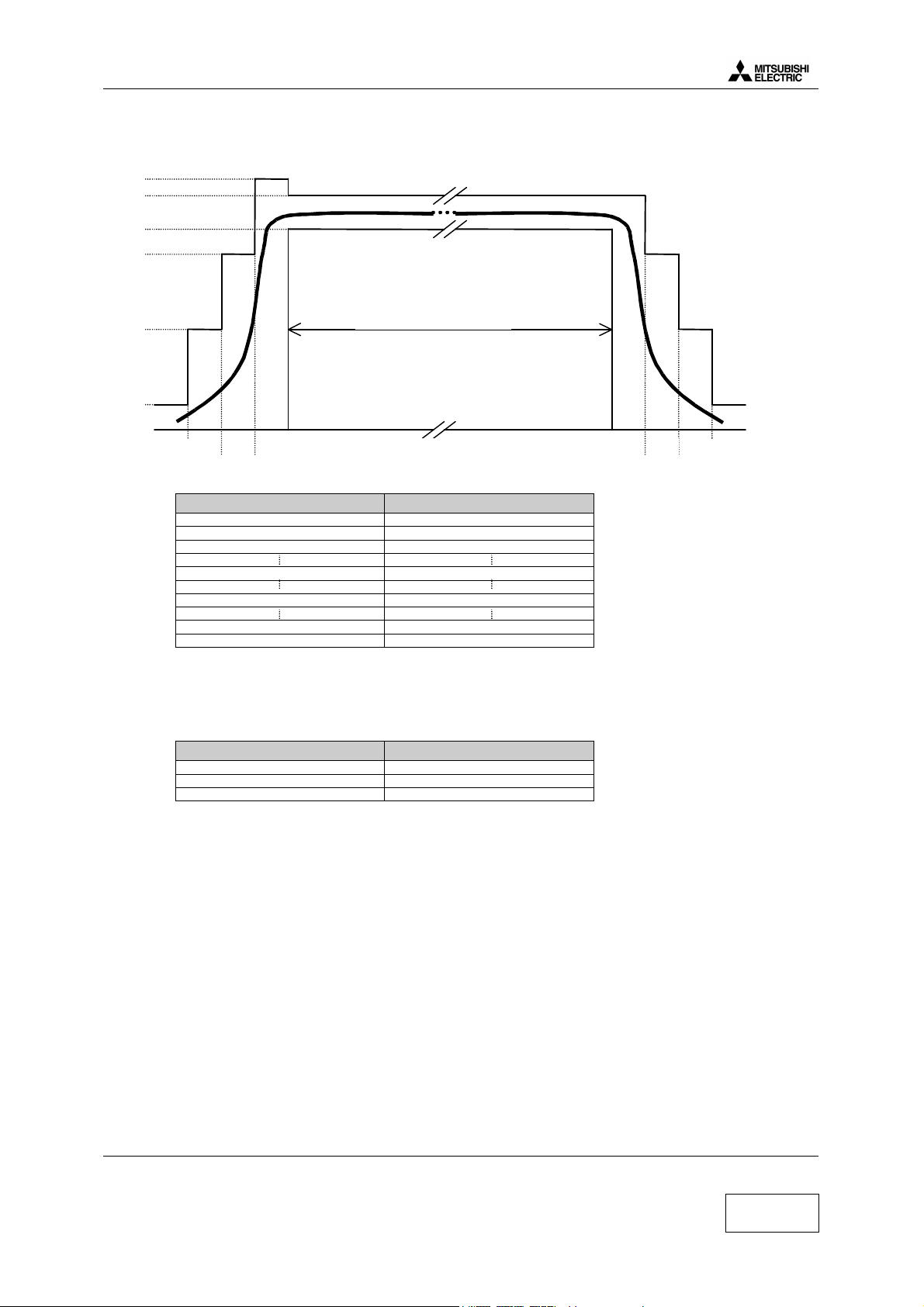
8µs
10µs
8µs
10µs
542.8
µ
s
COSMO
Power ramping: Check that the burst fits the mask below
Level
(dB)
+4
+1
-1
-6
-30
147 « useful » bits
-70
RX levels : Check the values for differents signal strength
RX LEVEL RSSI (dBm)
0 Less than -110 dBm
1 -110 to -109
2 -109 to -108
27 -84 to -83
50 -61 to -60
62 -49 to -48
63 Better than -48
Bit error : Check the value for different type
Check the Reception Bit Error Rates (RBER) and Frame Error Rates on channels 1, 62 and 124 at –102 dBm
for GSM band and on channels 512, 698 and 885 for the DCS band according the following specifications :
Bit error type Value
RBER Class Ib < 0.41 %
RBER Class II < 2.44 %
FER < 0.12%
4.c Buzzer and Speaker tests
Insert a test SIM in mobile set with battery.
The volume levels of the ring tone, key tones and incoming audio can be individually adjusted in the setting
menu.
• Press Menu by pressing choose Settings and validate by pressing joystick on right direction for Select
• Choose Tones by pressing on down direction and validate by pressing on right for Select
• Choose Volume by pressing on down direction and validate by pressing on right for Select
• Adjust Ring and Conversation to check buzzer and speaker
Mitsubishi Electric Telecom Europe S.A. Version C
ZA le Piquet, 35370 Etrelles Date: 10/00
Phone: +33 2 99 75 71 00
Fax: +33 2 99 75 71 47
11/20
Page 16

Level 2 Service Manual
COSMO
5. Service SOFTWARES
The software in the mobile consists of two files downloaded independantly.
The main part of this software is downloaded using IPL2000.
The settings file (ringing, customization…) is downloaded with MS Tools. MS tools also allows entry to test
mode in order to reset user data (security code) , to print labels (imei & factory name plate), to reset the
permanently blocked indicator providing you have the access rights.
5.a Software download with IPL2000
5.a.1 How to install IPL2000 software and equipment
Equipment description :
COM 1
IPL2000 is available on Windows 95, 98, NT4 OS and to install it, you need theses files :
(The files can be provided under one ZIP file)
Set up procedure :
PC CABLE COSMO DOWNLOAD
FK8T000510
Mobile without battery
1 Launch Setup.exe
2 Click on Next
3 Click on Next
4 Click on Next
5 Close the Mitsubishi Electric France window
6 Click on Finish
IPLTrium (IPL2000) is now installed in your computer and availlable in your ÿStart Menu
You are now ready to download the software.file.
Version C Mitsubishi Electric Telecom Europe S.A.
Date: 10/00 ZA le Piquet, 35370 Etrelles
12/20
Phone: +33 2 99 75 71 00
Fax: +33 2 99 75 71 47
Page 17
Level 2 Service Manual
COSMO
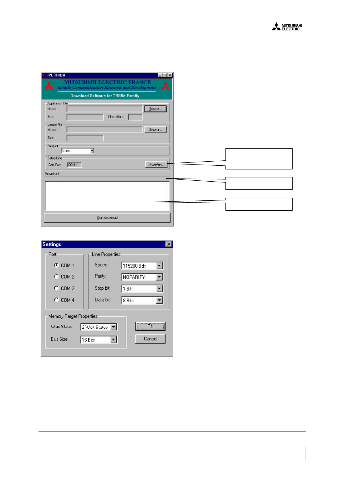
5.a.2 Software description
To launch IPL2000, use the start menu, then Pograms, then Mitsubishi Electric France, then IPL Trium.
Click here to adjust
Serial Parameters
Progress Indicator
Adjust the serial parameters as folowing
Information Window
Mitsubishi Electric Telecom Europe S.A. Version C
ZA le Piquet, 35370 Etrelles Date: 10/00
Phone: +33 2 99 75 71 00
Fax: +33 2 99 75 71 47
13/20
Page 18
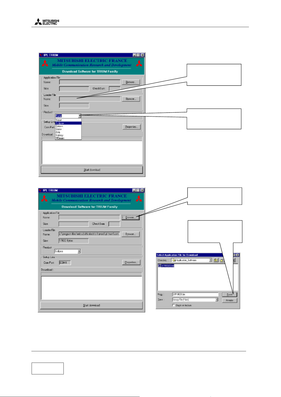
5.a.3 Start download
(Eclipse)
Level 2 Service Manual
COSMO
Loader File is
automotically set when
the product is selected
Click here to select the
product
Click here to select the
Sofware for download
Then choose the right
version and click on
Open to validate
Version C Mitsubishi Electric Telecom Europe S.A.
Date: 10/00 ZA le Piquet, 35370 Etrelles
14/20
Phone: +33 2 99 75 71 00
Fax: +33 2 99 75 71 47
Page 19

Level 2 Service Manual
COSMO
Then you see the green top led is blinking, the download is in progress.
5.a.4 End of Download
Click here to
Start download
Download completed is
displayed in the
information window
Mitsubishi Electric Telecom Europe S.A. Version C
ZA le Piquet, 35370 Etrelles Date: 10/00
Phone: +33 2 99 75 71 00
Fax: +33 2 99 75 71 47
15/20
Page 20

Level 2 Service Manual
COSMO
To check that download is succesfully completed, look at the top led of COSMO, The green led must be ON.
If the red top led is blinking your download is failled.
5.b Settings download with MS Tools
5.b.1 How to install MS Tools software and equipment
Equipment description :
Mobile with full battery
To COM1
PC CABLE COSMO DOWNLOAD
FK8T000510
MS Tools 7.00 is available on Windows 95, 98, NT4 OS and to install it you need theses 3 files :
Setup procedure :
1 Launch Setup.exe
2 Click on Finish
3 Click on OK
MS Tools is now installed on your computer and available in your ÿStart menu
You are now ready to download the setting file.
Version C Mitsubishi Electric Telecom Europe S.A.
Date: 10/00 ZA le Piquet, 35370 Etrelles
16/20
Phone: +33 2 99 75 71 00
Fax: +33 2 99 75 71 47
Page 21

Level 2 Service Manual
COSMO
5.b.2 Software description
Exit:
To quit MS Tools
(Click on is not availlable)
Mobile menu :
Download perso
Initialization data users
Mobile identification
Informatio
n window
Version of
MS Tools
Test Mode menu :
TEST MODE enter and exit
5.b.3 Start download
In TestMode menu, click on Start from NormalMode, then information window displays:
Mitsubishi Electric Telecom Europe S.A. Version C
ZA le Piquet, 35370 Etrelles Date: 10/00
Phone: +33 2 99 75 71 00
Fax: +33 2 99 75 71 47
17/20
Page 22

Level 2 Service Manual
COSMO
In Mobile menu, click on Download Personification, then, choose the right settings file and valid by select
5.b.4 End of download
In TestMode menu, click on Stop and go back to normal mode to close the test mode session.
Version C Mitsubishi Electric Telecom Europe S.A.
Date: 10/00 ZA le Piquet, 35370 Etrelles
18/20
Phone: +33 2 99 75 71 00
Fax: +33 2 99 75 71 47
Page 23

Level 2 Service Manual
COSMO
5.b.5 How to print labels using MS Tools
Equipment description:
COM1
COM2
ZEBRA
90XiII
Printer
PC CABLE COSMO DOWNLOAD
FK8T000510
mobile with battery
MS Tools software version 7.00 (or higher) is required to print labels.
This software is provided by MITSUBISHI ELECTRIC France under floppy format (2 floppies)
MS Tools is available on Windows 95, 98, NT4 OS and to install it you need theses 3 files:
Setup procedure:
1 Launch Setup.exe
2 Click on Finish
3 Click on OK
MS Tools is now installed on your computer and available in your ÿSTART menu . MS tools program does
not send information directly to ZEBRA 90Xi II printer, it sends information to NI VISA driver and NI VISA
driver sends information to ZEBRA 90Xi II printer.
Driver required: NI VISA
NI VISA driver is required and can be provided by MITSUBISHI ELECTRIC TELECOM EUROPE.
The NI VISA driver is located on NATIONAL INSTRUMENTS NI 488.2 CD-ROM
To install this driver on your PC, launch the setup.EXE which is located in the NI-VISA folder on the CDROM.
Mitsubishi Electric Telecom Europe S.A. Version C
ZA le Piquet, 35370 Etrelles Date: 10/00
Phone: +33 2 99 75 71 00
Fax: +33 2 99 75 71 47
19/20
Page 24

5.b.6 Print labels
In TestMode menu, choose Start from NormalMode, then Mobile menu became available.
In Mobile menu, choose Mobile identification, and then following screen will be displayed.
Level 2 Service Manual
COSMO
Click here to print
Click here to print
Version C Mitsubishi Electric Telecom Europe S.A.
Date: 10/00 ZA le Piquet, 35370 Etrelles
20/20
Phone: +33 2 99 75 71 00
Fax: +33 2 99 75 71 47
Page 25

Level 2 Service Manual
COSMO
6. SOFTWARE AND SETTING VERSION
To display the software and the perso (personalisation), connect a charged battery, press the power key. Wait
few seconds, then hold the * key and press 5807.
Then on the mobile, the following message is displayed,
For example:
To exit from the Software and Perso monitoring mode, press any key except power key
- - VERSION - - 21157001
- - - PERSO - - - 21433S00
7. OPERATOR DEBUGGING
To display the RX level (in dBm), insert the SIM card (from service provider or test SIM card using CMD in
manual test), connect a charged battery and press the power key. When the mobile displays the network (real
network or test network 001-01), hold the * key and press 4329
Then on the mobile, the following message is displayed,
For example : RX level (dBm)
B099 07 -085
MCC001 MNC01
1.a.1.1.1.1.1.1 And
other datas…
To exit from the Operator debugging mode, use the same command: hold the * key and press 4329
Mitsubishi Electric Telecom Europe S.A. Version C
ZA le Piquet, 35370 Etrelles Date: 10/00
Phone: +33 2 99 75 71 00
Fax: +33 2 99 75 71 47
21/20
Page 26
Level 2 Service Manual
COSMO
Mitsubishi Electric reserves the right to make changes to its products at any time to improve reliability or
manufacturability. Mitsubishi Electric does not assume any liability arising from the use of any device or circuit
described herein, nor does it convey any license under its patent rights or the rights of others.
Version C Mitsubishi Electric Telecom Europe S.A.
Date: 10/00 ZA le Piquet, 35370 Etrelles
22/20
Phone: +33 2 99 75 71 00
Fax: +33 2 99 75 71 47
 Loading...