

Page 1

GROUP 13
FUEL
CONTENTS
MULTIPOINT FUEL INJECTION (MPI). . . . . . . . . . . . . . . . . . . . 13A
MULTIPOINT FUEL INJECTION (MPI) <4G1>. . . . . . . . . . . . . . 13B
FUEL SUPPLY . . . . . . . . . . . . . . . . . . . . . . . . . . . . . . . . . . . . . . 13C
Page 2

GROUP 15
INTAKE AND
EXHAUST
CONTENTS
AIR INTAKE SYSTEM . . . . . . . . . . . . 15-2
AIR DUCT AND AIR CLEANER . . . . . . . . . 15-2
INTERCOOLER <4G1> . . . . . . . . . . . . . . . 15-3
INLET MANIFOLD <4A9>. . . . . . . . . . . . . . 15-4
INLET MANIFOLD <4G1> . . . . . . . . . . . . . 15-4
EXHAUST SYSTEM . . . . . . . . . . . . . . 15-5
EXHAUST MANIFOLD <4A9> . . . . . . . . . . 15-5
TURBOCHARGER <4G1> . . . . . . . . . . . . . 15-6
EXHAUST PIPE AND MUFFLER <4A9> . . 15-7
EXHAUST PIPE AND MUFFLER <4G1> . . 15-8
Page 3
15-2
INTAKE AND EXHAUST
AIR INTAKE SYSTEM
AIR INTAKE SYSTEM
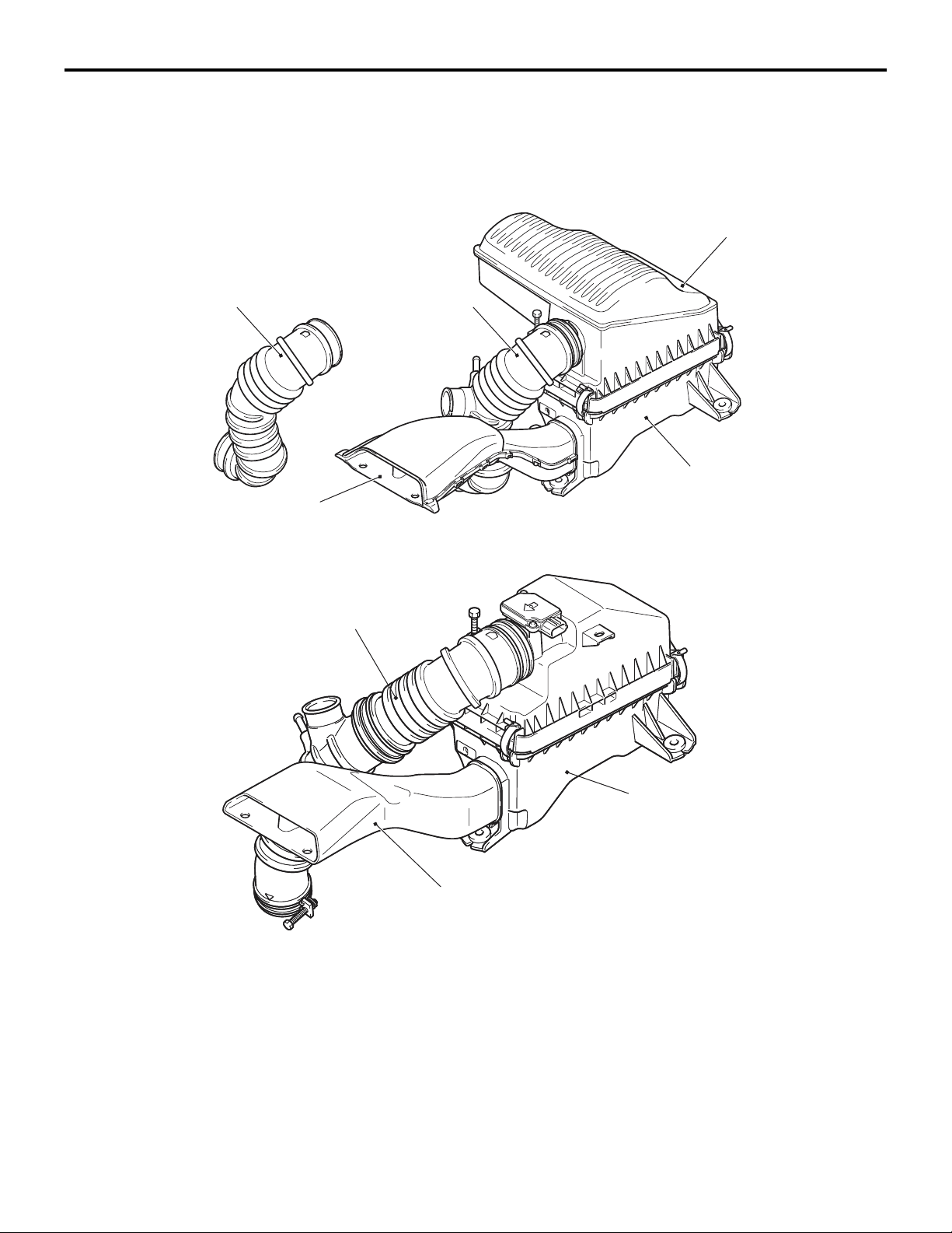
AIR DUCT AND AIR CLEANER
CONSTRUCTION DIAGRAM
<4A9>
Engine
air intake hose
<M/T>
Air cleaner intake duct
<4G1>
M2150004000504
Engine
air intake hose
<CVT>
Air cleaner resonator
Air cleaner assembly
AC601193
AB
Engine air intake hose
Air cleaner intake duct
• An air cleaner resonator has been adopted to
improve engine performance and reduce air
intake noise <4A9>.
• A front air intake system that actively sucks cooling air from the front through the top of the radiator has been adopted in order to improve engine
performance and reduce air intake noise.
Air cleaner assembly
AC402138
AC402138
AB
• For the air cleaner intake duct, a venturi duct with
a diaphragm on its path has been adopted to sup
press rise in air resistance and reduce air intake
noise.
• In consideration of industrial waste reduction and
global environment, recycled materials made
from eating utensils and the scraps have been
adopted for the air cleaner body and cover of the
air cleaner assembly.
-
Page 4
INTAKE AND EXHAUST
AIR INTAKE SYSTEM
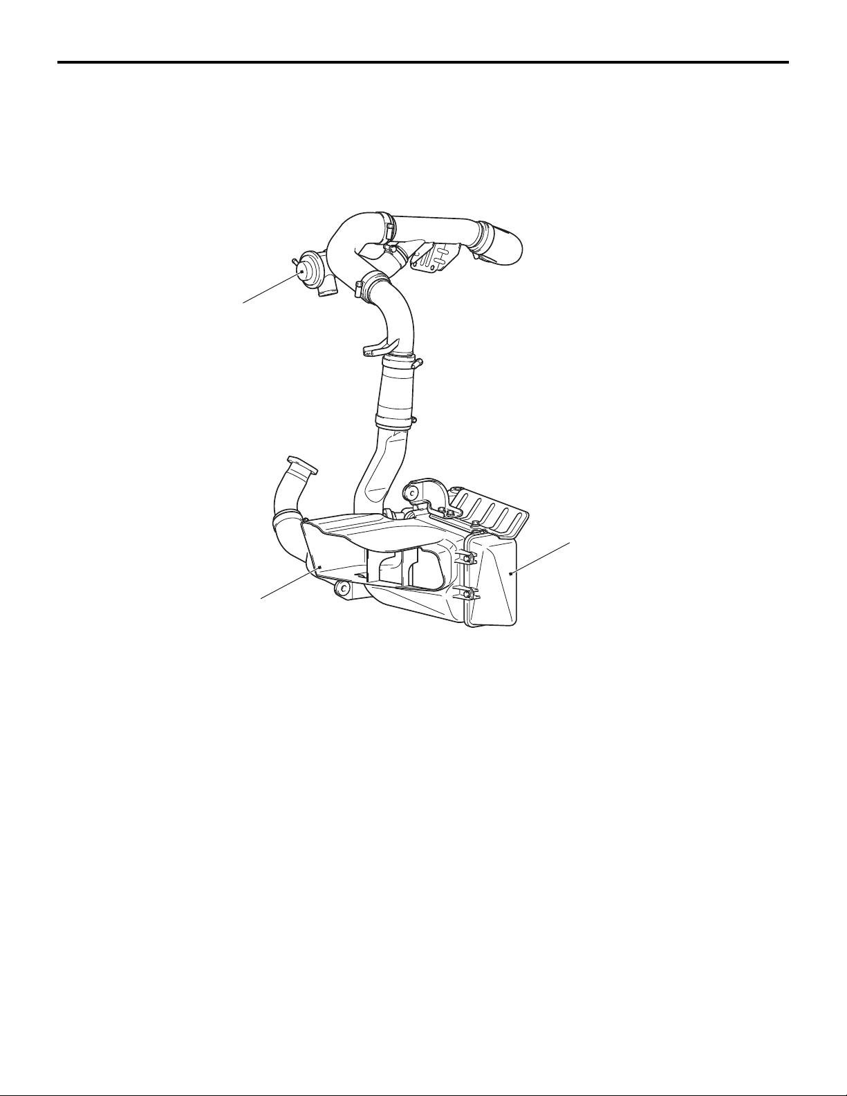
INTERCOOLER <4G1>
M2150007000246
An air cooled intercooler has been adopted to lower
the intake air temperature drastically and improve
engine performance.
CONSTRUCTION DIAGRAM
Air by-pass valve
15-3
Intercooler inlet air duct
Intercooler assembly
AC600080
AB
Page 5
15-4
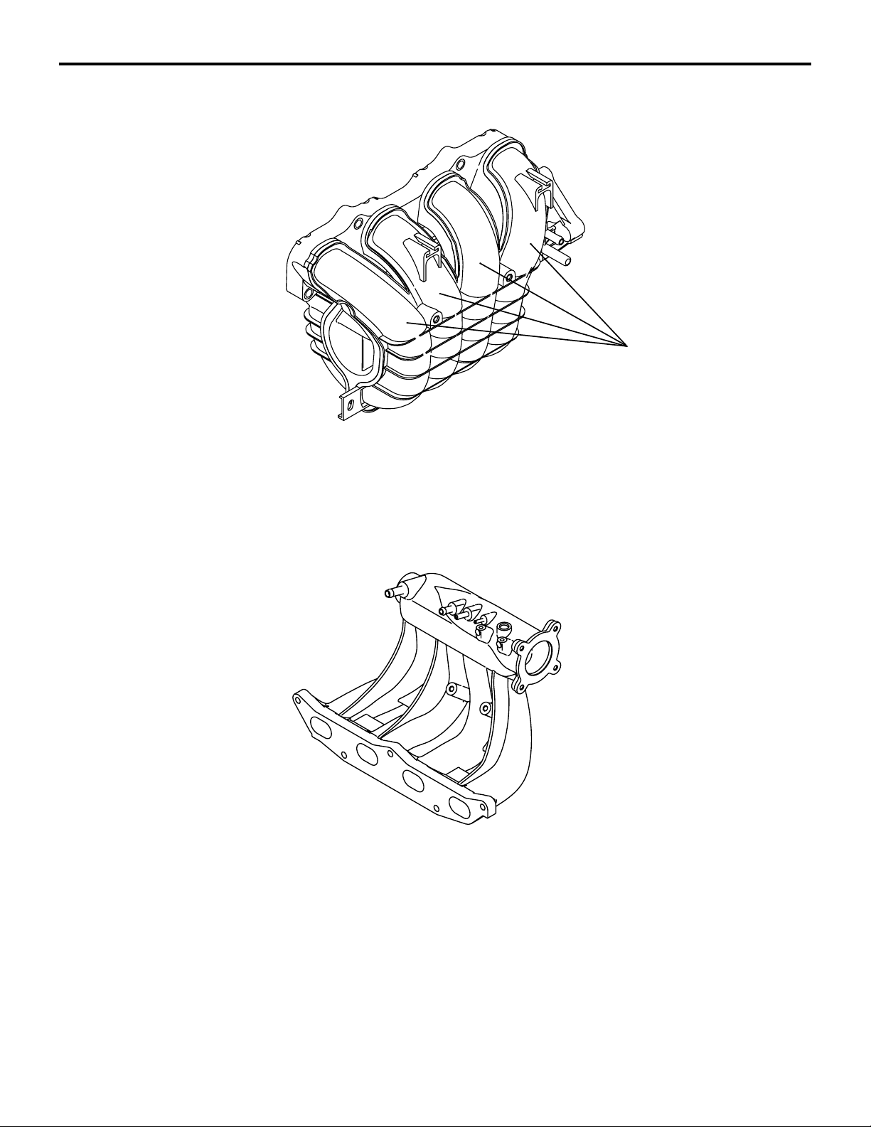
INLET MANIFOLD <4A9>
INTAKE AND EXHAUST
AIR INTAKE SYSTEM
M2150010000105
Inlet port
The inlet manifold is made of resin. The inlet ports
are curled for size and weight reduction.
INLET MANIFOLD <4G1>
AK305379
M2150010000116
AB
The port shape is changed to be optimum for the
vehicle with the turbocharger.
AK403235
Page 6
INTAKE AND EXHAUST
EXHAUST SYSTEM
EXHAUST SYSTEM
15-5
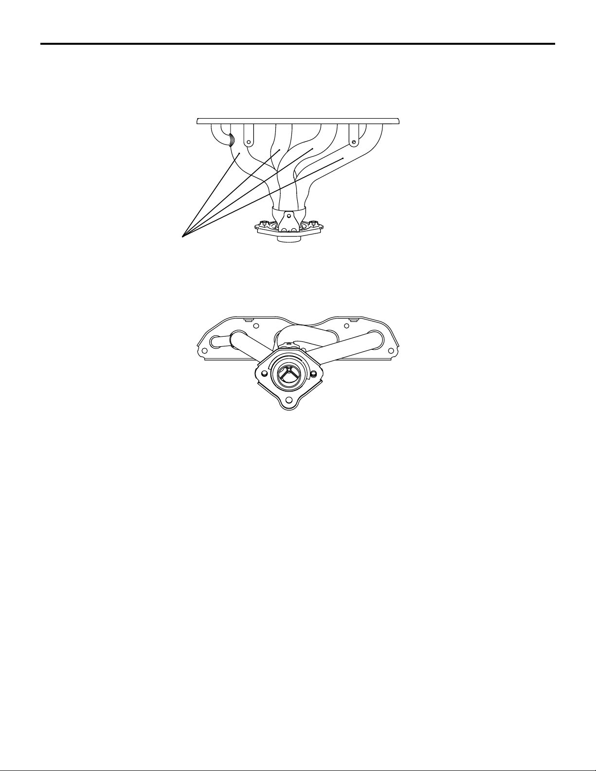
EXHAUST MANIFOLD <4A9>
Pipes
M2150006000317
The exhaust manifold consists of stainless steel
pipes, with all the ports being equal in length, to
achieve robust mid-range torque and weight reduc
tion.
AK402037
AD
-
Page 7
15-6
INTAKE AND EXHAUST
EXHAUST SYSTEM
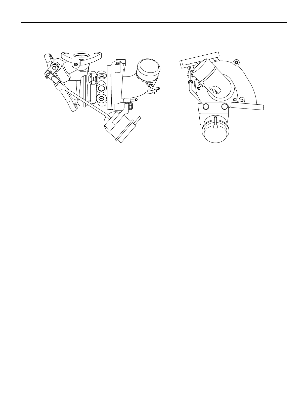
TURBOCHARGER <4G1>
Considering the balance among the engine output,
the response and the amount of the exhaust gases,
the optimized size is used .
M2150009000123
AK402141
Page 8
INTAKE AND EXHAUST
EXHAUST SYSTEM
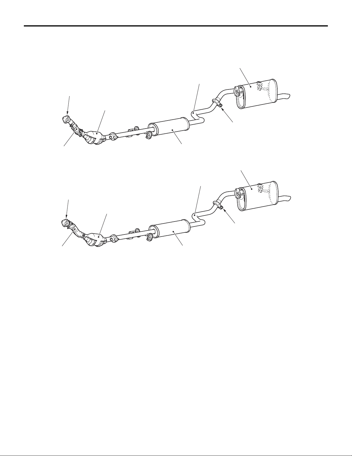
EXHAUST PIPE AND MUFFLER <4A9>
M2150003000642
CONSTRUCTION DIAGRAM
15-7
<M/T>
Annular joint
Front exhaust pipe
<CVT>
Annular joint
Under floor catalytic converter
Under floor catalytic converter
Centre exhaust pipe
Exhaust pre-muffler
Centre exhaust pipe
Exhaust main muffler
Insertion joint
Exhaust main muffler
Insertion joint
AC601362
AB
Front exhaust pipe
Exhaust pre-muffler
Exhaust pipe consisting of three separation system:
front exhaust pipe, centre exhaust pipe, and exhaust
main muffler, has the following features:
• An exhaust pre-muffler has been installed to the
centre exhaust pipe in order to reduce exhaust
noise.
• An insertion joint has been adopted for the connection between the centre exhaust pipe and the
exhaust main muffler to save the weight of the
exhaust system.
AC601363
• The under floor catalytic converter has been
moved closer to the engine side to improve
exhaust gas performance.
• An annular joint has been adopted for the connection between the exhaust manifold and the
front exhaust pipe to reduce the exhaust pipe's
vibration from the engine side.
AB
Page 9
15-8
INTAKE AND EXHAUST
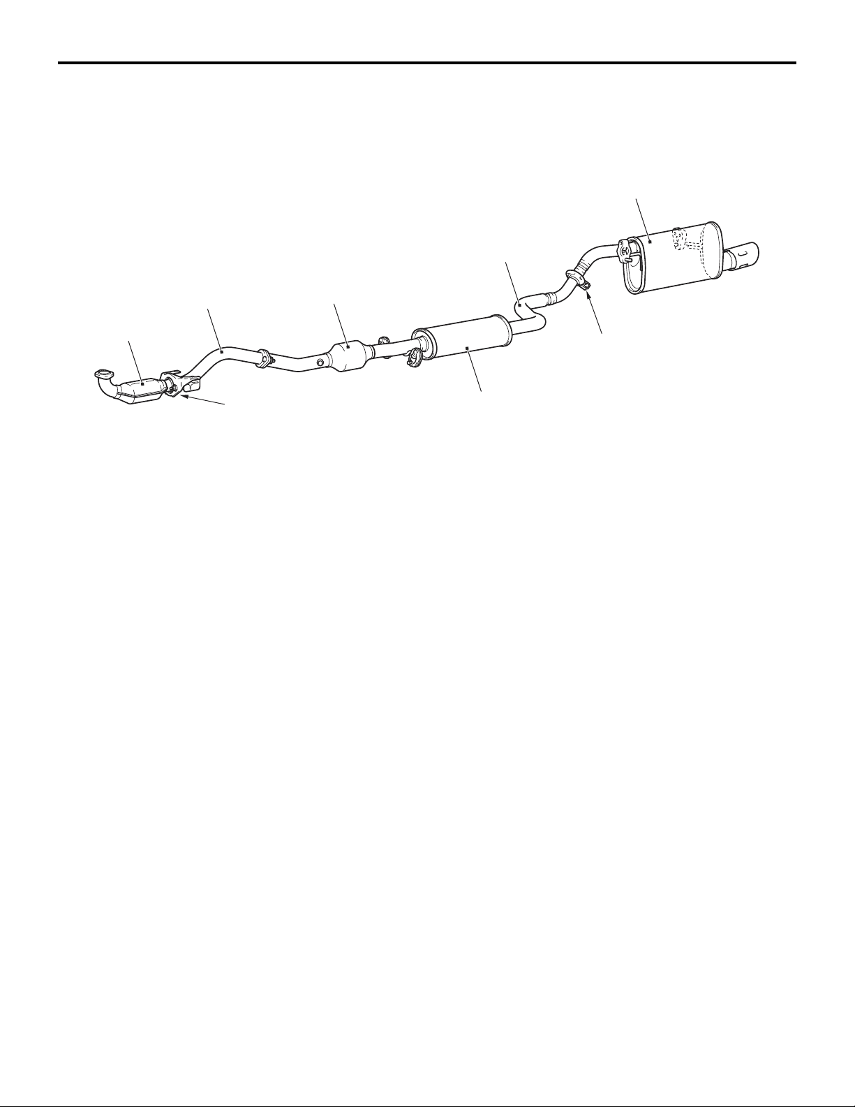
EXHAUST PIPE AND MUFFLER <4G1>
M2150003000653
CONSTRUCTION DIAGRAM
Under floor
Front
catalytic
converter
Front exhaust pipe
catalytic converter
EXHAUST SYSTEM
Exhaust main muffler
Centre exhaust pipe
Insertion joint
Annular joint
Exhaust pipe consisting of three separation system:
front exhaust pipe, centre exhaust pipe, and exhaust
main muffler, has the following features:
• An exhaust pre-muffler has been installed to the
centre exhaust pipe in order to reduce exhaust
noise.
• An insertion joint has been adopted for the connection between the centre exhaust pipe and the
exhaust main muffler to save the weight of the
exhaust system.
Exhaust pre-muffler
AC601366
• An annular joint has been adopted for the connection between the front exhaust pipe and the
front catalytic converter has been adopted to
reduce vibration from the engine side.
• A front catalytic converter and an under floor catalytic converter have been adopted to improve
exhaust gas performance.
AB
Page 10

GROUP 17
ENGINE AND
EMISSION
CONTROL
CONTENTS
ENGINE CONTROL . . . . . . . . . . . . . . 17-2
ACCELERATOR SYSTEM . . . . . . . . . . . . . 17-2
EMISSION CONTROL . . . . . . . . . . . . 17-3
GENERAL INFORMATION <4A9> . . . . . . . 17-3
GENERAL INFORMATION <4G1> . . . . . . . 17-4
Page 11
17-2
ENGINE AND EMISSION CONTROL
ENGINE CONTROL
ENGINE CONTROL
ACCELERATOR SYSTEM
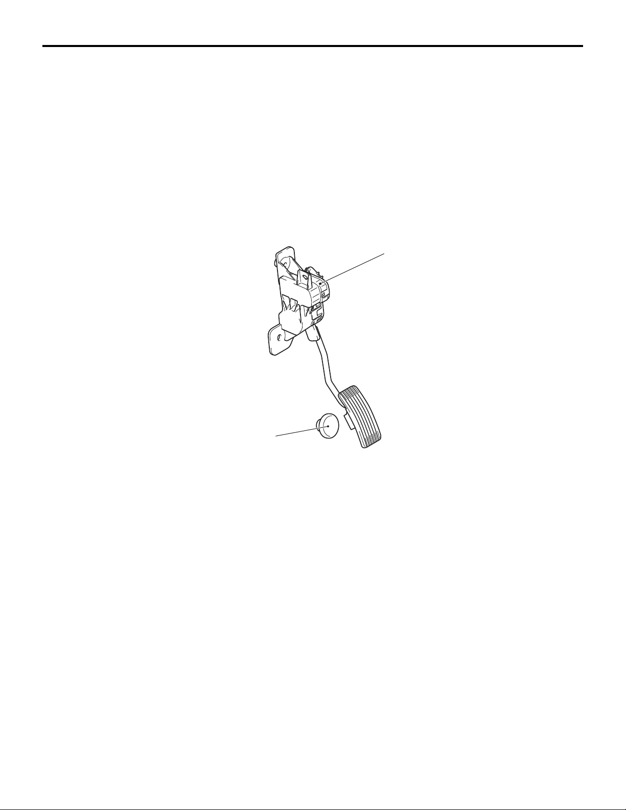
M2170003000310
For the accelerator system, an electronic throttle
valve control system has been adopted, eliminating
of an accelerator cable. This system detects the
amount of the accelerator pedal movement by using
a accelerator pedal-position sensor in the accelerator
pedal assembly for electronic control of the throttle
valve angle.
CONSTRUCTION DIAGRAM
Accelerator pedal assembly
(Built-in accelerator pedal
position sensor)
Accelerator pedal
arm stopper
AC206106
AD
Page 12
ENGINE AND EMISSION CONTROL
EMISSION CONTROL
EMISSION CONTROL
17-3
GENERAL INFORMATION <4A9>
Although the emission control systems are basically
the same as those of the 4G1-Non-Turbo engine
used in the COLT, the following improvements have
been added.
System Remarks
Crank case ventilaton system Closed type
Evaporative emission control system Electronic control type with duty signal
Exhaust gas recirculation (EGR) system <CVT> Electronic control (stepper motor) type
Air/fuel ratio closed loop control Oxygen sensor signal used
Catalytic converter Three-way catalytic converter
• The adoption of the catalytic converter just
beneath exhaust manifold realizes the earlier
activation.
• The adoption of the dual oxygen sensor has
increased reliability air/fuel ratio control.
•
The abolition of the EGR system <M/T>.
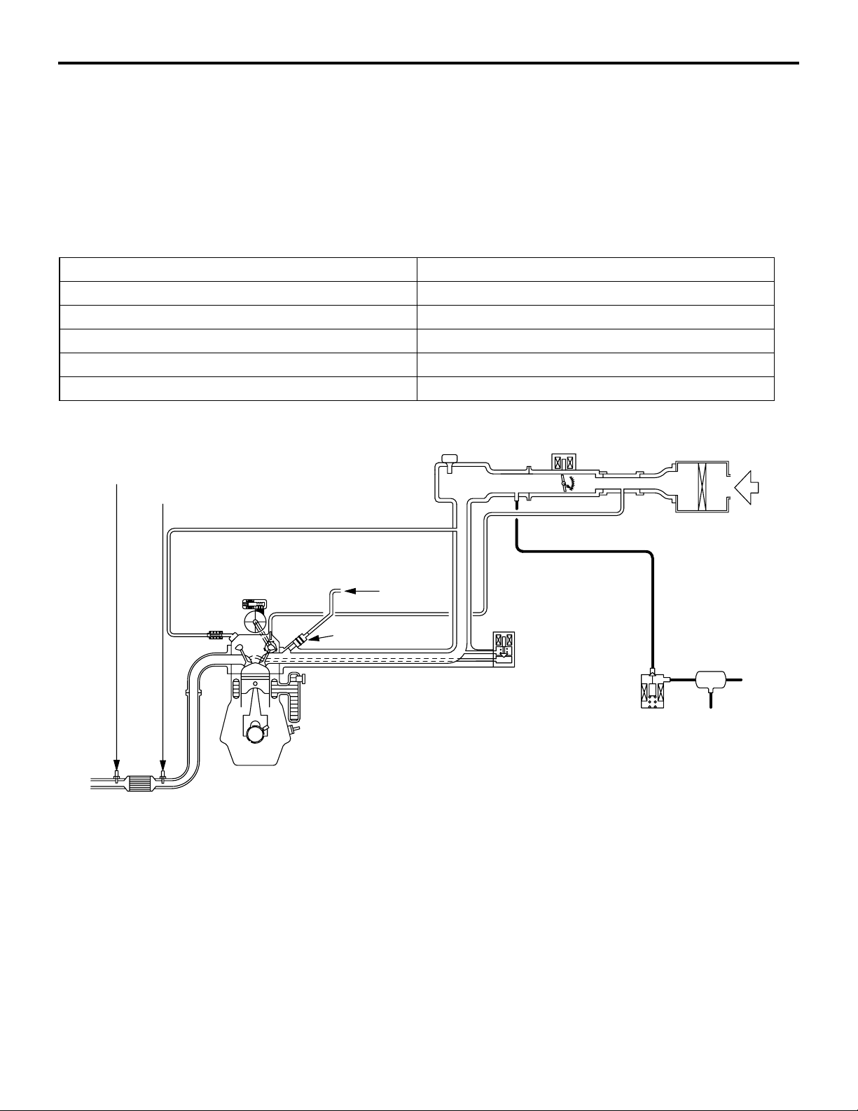
EMISSION CONTROL SYSTEM DIAGRAM
Oxygen sensor (rear)
Oxygen sensor (front)
M2171000100838
Air
inlet
PCV valve
Catalytic converter
Injector
From
fuel pump
EGR valve
(stepper motor)
<CVT>
Purge control
solenoid valve
Canister
AK402829
AC
Page 13
17-4
ENGINE AND EMISSION CONTROL
EMISSION CONTROL
GENERAL INFORMATION <4G1>
Although the emission control systems are basically
the same as those of the 4G1-Non-Turbo engine
used in the COLT, the following improvements have
been added.
• The adoption of the catalytic converter just
beneath turbo charger and under the floor
increased the performance of the emission con
-
trols.
System Remarks
Crank case ventilaton system Closed type
Evaporative emission control system Electronic control type with duty signal
Air/fuel ratio closed loop control Oxygen sensor signal used
Catalytic converter Three-way catalytic converter
• The adoption of the check valve between the
purge control solenoid valve and the canister pro
tects the regurgitation as turbocharging.
•
The abolition of the EGR system
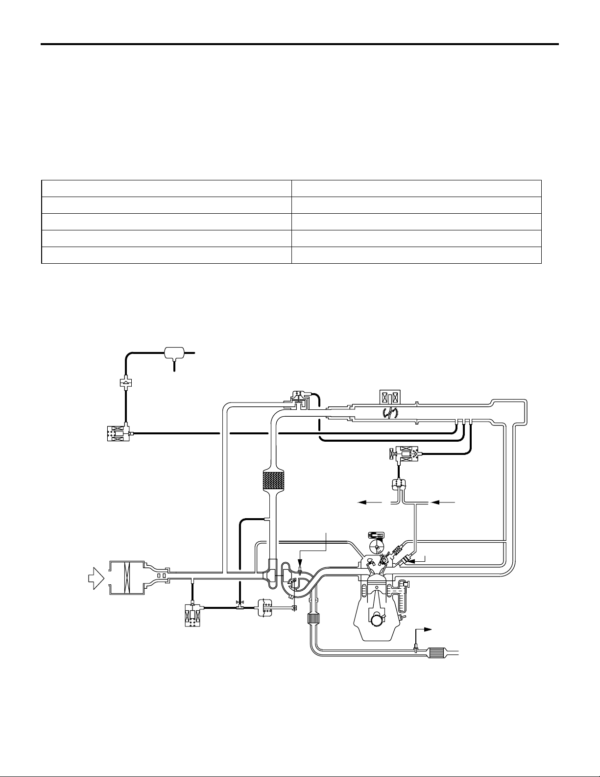
EMISSION CONTROL SYSTEM DIAGRAM
M2171000100849
-
Air
inlet
Check valve
Purge control
solenoid valve
Canister
Waste gate
solenoid valve
Waste gate
actuator
Fuel pressure control
solenoid valve
To
fuel tank
Oxygen sensor
(front)
Catalytic
converter
Fuel pressure
regulator
From
fuel pump
Injector
Oxygen sensor
(rear)
Catalytic
converter
AK600530AB
Page 14

GROUP 23
CONTINUOUSLY
VARIABLE
TRANSMISSION
(CVT)
CONTENTS
CVT. . . . . . . . . . . . . . . . . . . . . . . . . . . 23-2
GENERAL INFORMATION. . . . . . . . . . . . . 23-2
ELECTRONIC CONTROL SYSTEM. . . . . . 23-3
EEPROM. . . . . . . . . . . . . . . . . . . . . . . . . . . 23-3
CONTROLLER AREA NETWORK (CAN)
COMMUNICATION . . . . . . . . . . . . . . . . . . . 23-3
RATIO PATTERN . . . . . . . . . . . . . . . . . . . . 23-3
DIAGNOSIS CLASSIFICATION TABLE . . . 23-4
ATF WARMER (ATF COOLER) . . . . . . . . . 23-5
TRANSMISSION CONTROL . . . . . . . 23-6
GENERAL INFORMATION . . . . . . . . . . . . . 23-6
SELECTOR LEVER ASSEMBLY . . . . . . . . 23-7
CVT ERRONEOUS OPERATION
PREVENTION MECHANISMS . . . . . . . . . . 23-8
Page 15

23-2
CONTINUOUSLY VARIABLE TRANSMISSION (CVT)
CVT
CVT
GENERAL INFORMATION
M2231000100165
The F1C1A transmission is adopted for the CVT.
This transmission is basically the same as conven
tional transmission.
The ATF warmer (ATF cooler) is adopted.
-
SPECIFICATIONS
Item Specification
Transmission model F1C1A
Engine model 4A91
Tor qu e co nv er te r Type 3-element, 1-stage, 2-phase type
Lock-up Provided
Stall torque ratio 2.0
Transmission type Forward automatic continuously variable (steel belt type),
1st in reverse
Gear ratio Forward 2.319 − 0.445
Reverse 2.588
Clutch A pair of multi-plate system
Brake A pair of multi-plate system
Manual control system P-R-N-D-Ds-L (smart shift)
Function Variable speed control Yes
Line pressure control Yes
Direct engagement control Yes
N-D/N-R control Ye s
Shift pattern control Yes
Self-diagnosis Yes
Failsafe Ye s
Oil pump Type External gear pump
Configuration Built-in (chain drive)
Control method Electronic control (INVECS-III)
Transmission oil Specified lubricants DIA QUEEN ATF SP III
Quantity L 8.1
Page 16
CONTINUOUSLY VARIABLE TRANSMISSION (CVT)
ELECTRONIC CONTROL SYSTEM
CVT
23-3
EEPROM
M2231012000024
Because EEPROM has been used, even if the battery terminals or control unit connectors are disconnected, the necessary learned values are stored in
the engine-CVT-ECU to prevent a loss of shift qual
ity. (Initialisation is available by M.U.T.-III).
CONTROLLER AREA NETWORK (CAN)
COMMUNICATION
CAN* communication has been adopted for communication with other ECUs in order to decrease the
number of wires and ensure information transmis
sion. For CVT control, the engine-CVT-ECU receives
the following signals.
CAN COMMUNICATION INPUT SIGNAL TABLE
Input signal Transmitter ECU
Average vehicle speed signal from drive wheels ABS-ECU
Motor current signal EPS-ECU
EPS warning lamp illumination request signal
Compressor signal Meter and A/C-ECU
NOTE: *: For more information about CAN (Controller Area Network), refer to GROUP 54C P.54C-2.
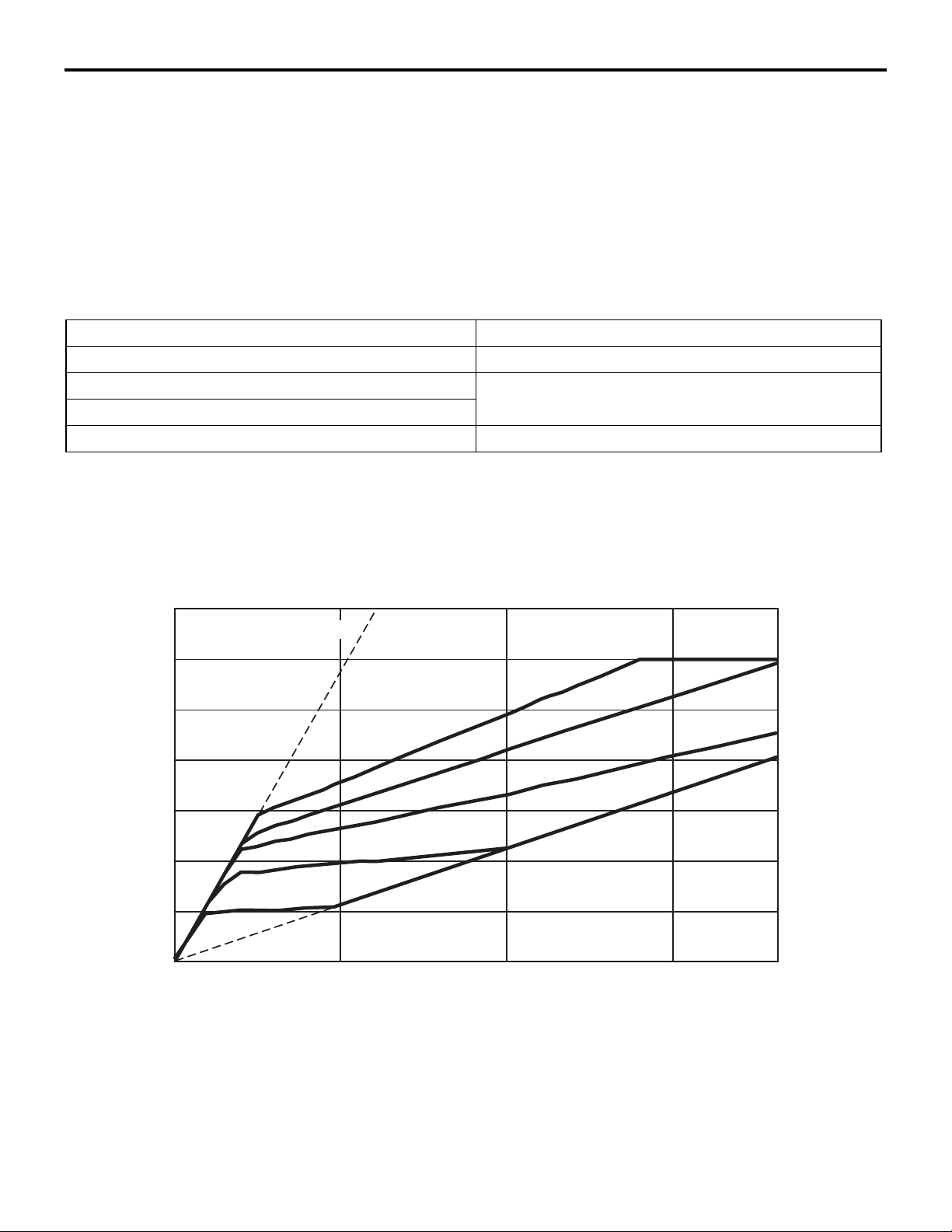
RATIO PATTERN
M2231013000061
Engine speed
(r/min)
7,000
LOW
M2231017000018
-
6,000
5,000
4,000
3,000
2,000
1,000
Accelerator
fully open
40%
Accelerator
fully closed, 20%
0
Vehicle speed (km/h)
80%
60%
100 15050
OD
AC403740
AE
Page 17

23-4
CONTINUOUSLY VARIABLE TRANSMISSION (CVT)
CVT
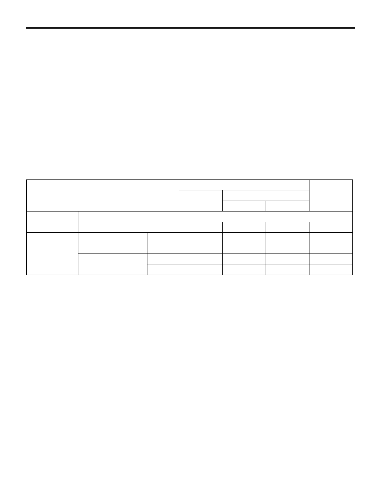
DIAGNOSIS CLASSIFICATION TABLE
M2231015000056
Item Diagnosis Data list Actuator
Code No. Trouble symptoms Item No. Display
Crank angle sensor
CVT fluid temperature sensor 15 Open circuit 08
− −
16 Short circuit
01 r/min
°C −
test
−
Line pressure sensor 18 Open circuit 09 MPa
19 Short circuit
Turbine speed sensor 22 Open circuit 02 r/min
Primary speed sensor 23 Open circuit 03 r/min
26 System failure
Secondary speed sensor 24 Open circuit 04 r/min
25 System failure
Accelerator pedal position sensor (APS)
Primary pressure sensor 27 Open circuit 11 MPa
Gear ratio
Line pressure control solenoid valve 31 Open circuit/short
Shift control solenoid valve 32 Open circuit 15 % 02
Damper clutch control solenoid valve 33 Open circuit 14 % 03
Clutch pressure control solenoid valve 34 Open circuit 17 % 04
− −
28 Short circuit
− −
circuit
36 Short circuit
37 Short circuit
06 mV
12 Displays the
gear ratio.
16 % 01
−
−
−
−
−
−
−
38 Short circuit
Shift system 42 System failure
Damper clutch system 44 System failure 10 r/min
45
Clutch system 46 System failure
48
Inhibitor switch 51 Open circuit 26 P/R/N/D/Ds/L
52 Short circuit
Stop lamp switch 53 Open circuit 33 ON/OFF
54 Short circuit
Battery voltage
CVT control relay 56 Open circuit 25 V 11
Steel belt system 59 System failure
Line pressure system 57 System failure
− −
71
72
− − −
− − −
24 V
− − −
− − −
−
−
−
−
Page 18
CONTINUOUSLY VARIABLE TRANSMISSION (CVT)
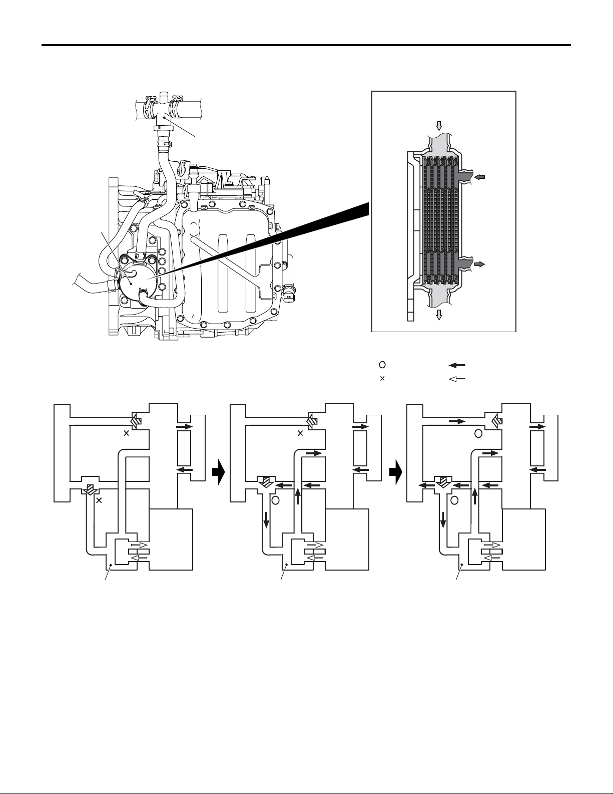
ATF WARMER (ATF C OOL ER)
Thermo valve
ATF Warmer
(ATF Cooler)
M2230000600082
CVT
23-5
Sectional view
Engine coolant
ATF
Thermostat
Thermo
Radiator
valve
ATF warmer (ATF cooler)
Engine
CVT CVT CVT
<Engine coolant temperature:
75˚C or less>
Engine coolant flows through
the heater only.
Heater
Radiator
ATF warmer (ATF cooler)
<Engine coolant temperature:
75 - 85˚C>
Engine coolant flows through
the heater and the ATF warmer.
Thermostat
Thermo
valve
The ATF warmer (ATF cooler) is adopted. (the ATF
cooler incorporating the radiator is not adopted)
At the start of running, the temperature of the engine
coolant rises earlier than that of the ATF. The ATF
warmer utilizes this characteristic to raise the ATF
temperature as early as possible to an appropriate
level (70 - 80
°C). It also controls fluid temperature
Engine
: Valve open
: Valve closed
Heater
: Engine coolant
: ATF
Thermostat
Thermo
Radiator
valve
ATF warmer (ATF cooler)
AC403052
Engine
AC
Heater
<Engine coolant temperature:
85˚C or more>
Engine coolant flows through
AC403006
all the sections.
AC
stably and reduces ATF agitation resistance to
improve fuel consumption ratio.
In addition, a thermo-valve has been adopted to
restrict the engine coolant supply to the ATF warmer
(ATF cooler) until the engine coolant temperature
reaches the appropriate temperature when low tem
perature start in winter, giving the priority to the heating performance.
Page 19
23-6
CONTINUOUSLY VARIABLE TRANSMISSION (CVT)
TRANSMISSION CONTROL
TRANSMISSION CONTROL
GENERAL INFORMATION
M2232000100447
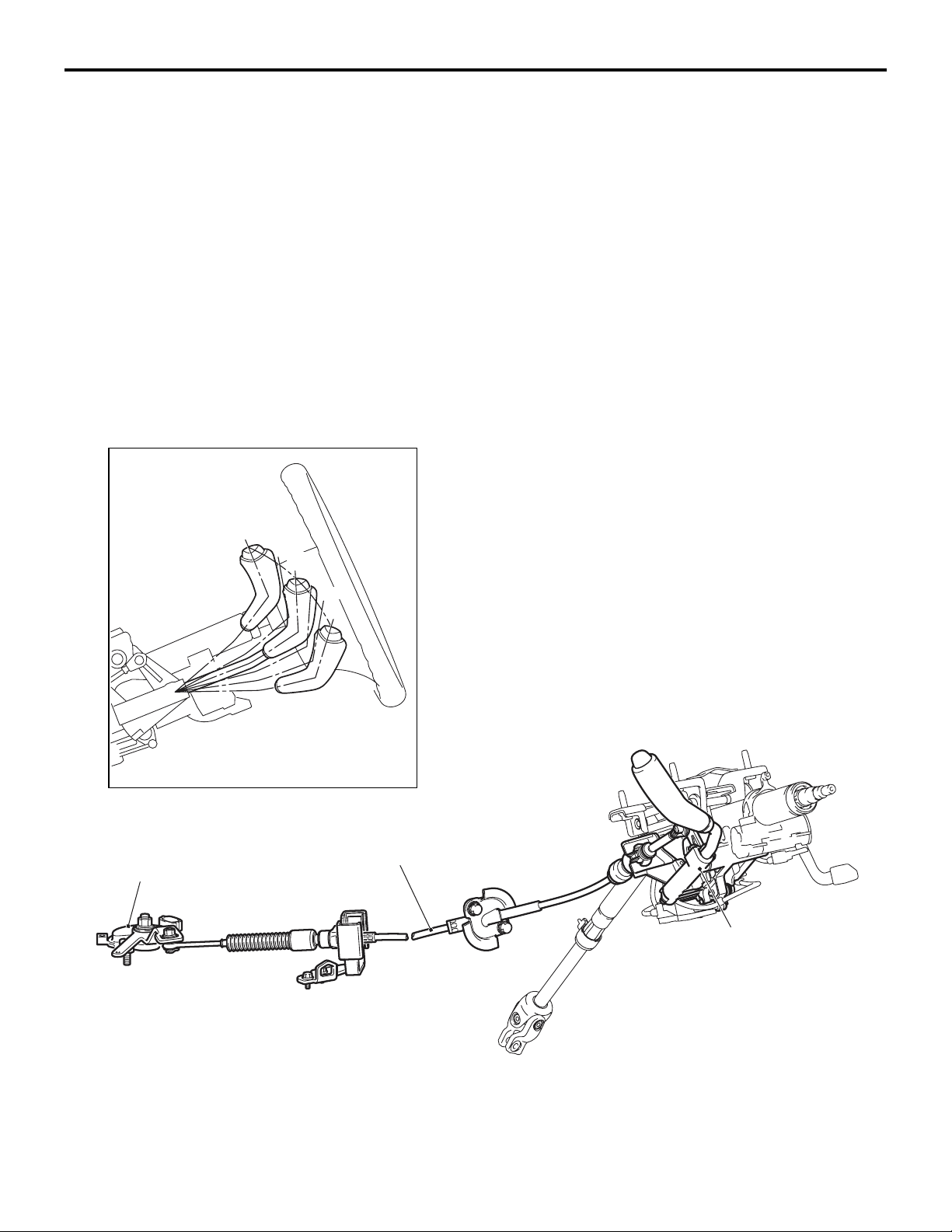
• A smart shift type selector lever has been
adopted in order to facilitate walkthrough
between the seats.
• A gun grip type selector lever knob has been
adopted for better operation and easier visual
recognition of the switches arranged in the centre
panel.
• The selector lever assembly has been a single
unit made by aluminium die casting for better
accuracy and fewer parts, resulting in the light
weight and compact structure.
COMPONENT VIEW
P
R
N
D
Ds
L
• The selector lever has been designed to be compact and appropriately configured not to interfere
with the energy absorbing mechanism on the
steering column upon impact of the vehicle.
• In order to prevent abrupt start by erroneous
operation of selector lever, a CVT erroneous
operation prevention mechanism (the shiftlock
mechanism and key interlock mechanism) has
been adopted.
-
Inhibitor switch
AC206842
Transmission
control cable
Selector lever
assembly
AC207638
AC206864
AB
Page 20
CONTINUOUSLY VARIABLE TRANSMISSION (CVT)
SELECTOR LEVER ASSEMBLY
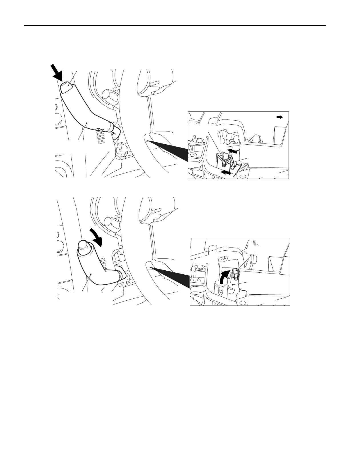
Push button
TRANSMISSION CONTROL
M2232002000190
Detent pin
23-7
Front of vehicles
Selector lever
(P position)
Selector lever
(except for P position)
AC206896
AC206897
A
Lock cam
AC206898
Detent pin
Detent block
AC206899
Operation
1. When the selector lever is in the P position, the
detent pin is engaged with the lock cam. When
the pushbutton on the selector lever is pressed,
the detent pin moves in the direction A as illustrated in the figure to rotate the lock cam.
2. When the detent pin rotates the lock cam to disengage, the selector lever can go over the protruding part of the detent block. This enables
shifting the selector lever.
AC207644
AB
Page 21
23-8
CONTINUOUSLY VARIABLE TRANSMISSION (CVT)
TRANSMISSION CONTROL
CVT ERRONEOUS OPERATION PREVENTION MECHANISMS
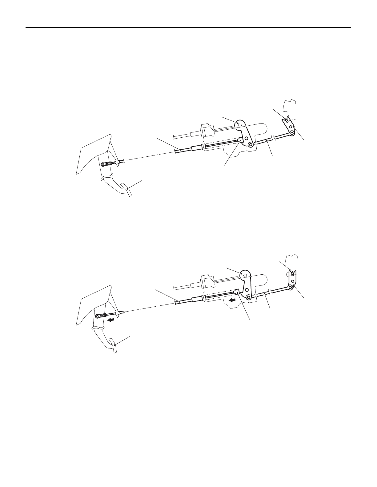
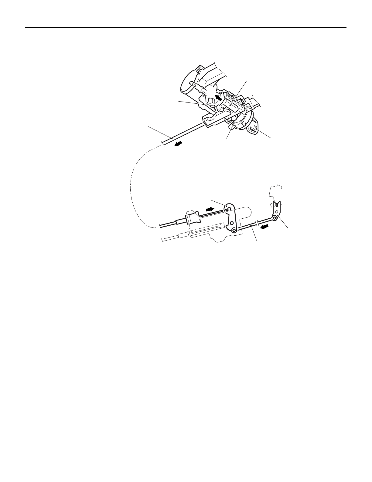
SHIFT LOCK MECHANISM
Only when the following two conditions are satisfied,
the selector lever can be shifted from the P position
to another position:
• When the brake pedal is depressed
• When the ignition key is in other than the LOCK
(OFF) position
When the brake pedal is not depressed
Detent pin
Lever
Shiftlock cable
Stopper
Brake pedal
M2232003000104
Lock cam
Rod
When the selector lever is in the P position with the
brake pedal not depressed, the shiftlock cable stop
per keeps the lever locked so that the rod and lock
cam do not move.
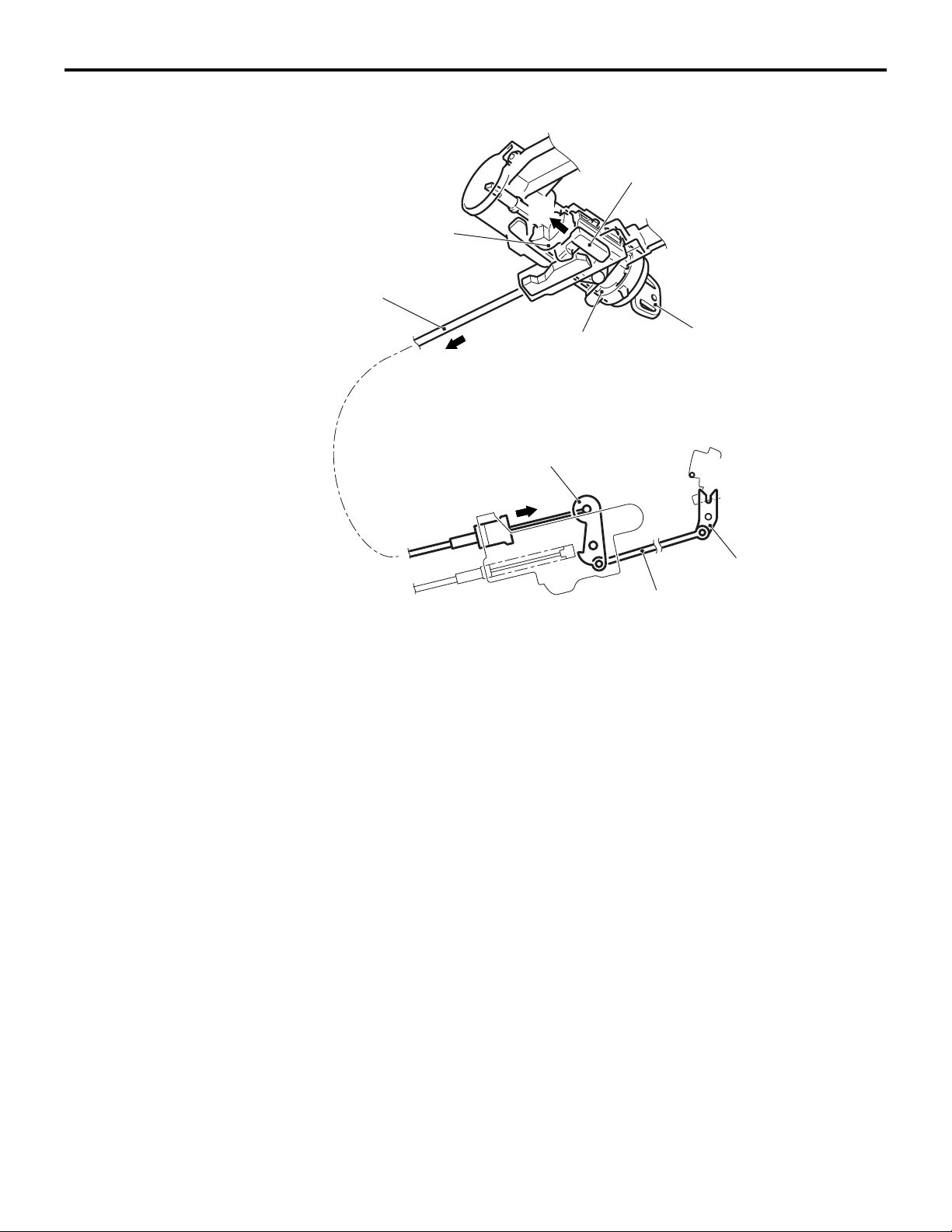
When the brake pedal is depressed
Shiftlock cable
Brake pedal
When the brake pedal is depressed, the stopper is
pulled by the shiftlock cable so that the lever
becomes unlocked.
Then the lock cam linked to the rod can also rotate
so that the selector lever can be shifted from the P
position to another position by pressing the pushbut
ton.
As a result of this, the pushbutton of the selector
-
lever linked to the detent pin cannot be pressed and
the selector lever cannot be shifted from the P posi
tion to another position.
Detent pin
Lever
Lock cam
Rod
Stopper
NOTE: When the brake pedal is depressed with the
ignition key in the LOCK (OFF) position, the selector
lever cannot be shifted from the P position to another
position.
-
AC206902
AC206903
AB
-
AB
Page 22
CONTINUOUSLY VARIABLE TRANSMISSION (CVT)
TRANSMISSION CONTROL
23-9
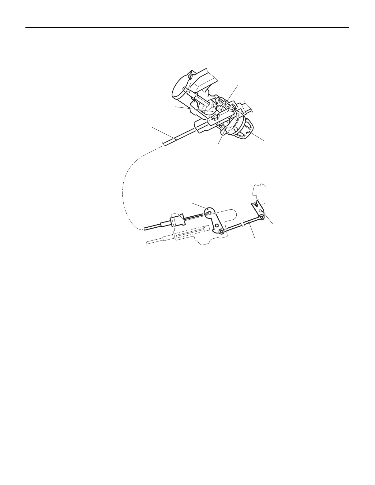
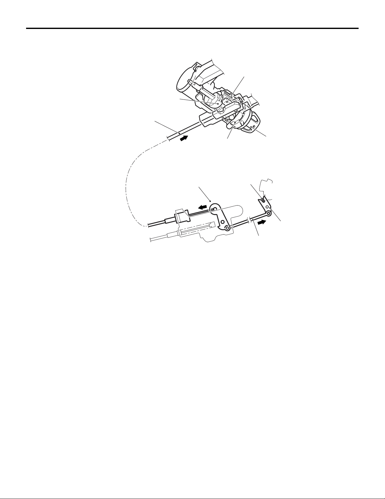
When the ignition key is in the LOCK (OFF) position or pulled out (With the selector
lever in the P position)
Slider
Projection of rotor
Key interlock cable
Ignition key
Engine starting
switch assembly
LOCK (OFF) position
In the engine starting switch assembly, the slider is
engaged with the groove of the key interlock cable,
and the slider is locked by the projection of the rotor
so that the key interlock cable as well as the lever,
rod, and lock cam does not move.
Lever
Lock cam
Rod
AC206911
As a result of this, any attempt to shift the selector
lever is prevented. The pushbutton on the selector
lever cannot be pressed because the lock cam does
not rotate, then the selector lever cannot be shifted
from the P position to another position.
AB
Page 23
23-10
CONTINUOUSLY VARIABLE TRANSMISSION (CVT)
TRANSMISSION CONTROL
When the ignition key is in other than the LOCK (OFF) position (With the selector
lever in the P position)
Slider
A
Projection of rotor
Key interlock cable
The rotor in the engine starting switch assembly has
a notch between ACC and START so that the slider
becomes unlocked.
Then the slider can move in the direction A as illustrated in the figure to allow the lock cam to rotate so
that the selector lever can be shifted from the P posi
tion to another position by pressing the pushbutton.
KEY INTERLOCK MECHANISM
When the selector lever is not in the P position, the
ignition key cannot be turned to the LOCK (OFF)
position and pulled out.
Engine starting
switch assembly
Lever
Ignition key
ACC to START
position
Lock cam
Rod
AC206912
NOTE: When the ignition key is in other than the
LOCK (OFF) position with the brake pedal not
depressed, the selector lever cannot be shifted from
the P position to another position.
-
AB
Page 24
CONTINUOUSLY VARIABLE TRANSMISSION (CVT)
TRANSMISSION CONTROL
When pulling out the key with the selector lever in other than the P position
Slider
B
Projection of rotor
Key interlock cable
23-11
A
The lock cam is kept in a rotated condition, and the
key interlock cable is kept pulled in direction A as
illustrated in the figure. In this state, the slider in the
engine starting switch assembly is moved and locked
in direction B as illustrated in the figure.
Engine starting
switch assembly
Lever
A
Ignition key
ACC to START
position
Rod
Lock cam
AC206912
AC
As a result of this, any attempt to turn the ignition key
to the LOCK (OFF) position is prevented because
the slider prevents the rotor from rotating, and the
ignition key can only turn up to the ACC position and
cannot be pulled out.
Page 25
23-12
CONTINUOUSLY VARIABLE TRANSMISSION (CVT)
TRANSMISSION CONTROL
When pulling out the key with the selector lever in the P position
Slider
Projection of rotor
Key interlock cable
When releasing the pushbutton on the selector lever
with the selector lever in the P position, the lock cam
is rotated by the detent pin. Then the key interlock
cable is moved by the lock cam in direction A as illustrated in the figure.
A
Engine starting
switch assembly
Lever
A
Detent pin
Ignition key
ACC to START
position
Lock cam
Rod
AC206911
As a result of this, the slider in the engine starting
switch assembly is unlocked. The rotor can then turn,
and the ignition key can be pulled out by turning it to
the LOCK (OFF) position.
AC
Page 26

GROUP 26
FRONT AXLE
CONTENTS
GENERAL INFORMATION . . . . . . . . 26-2
Page 27
26-2
FRONT AXLE
GENERAL INFORMATION
GENERAL INFORMATION
The front axle consists of front hub, wheel bearing,
knuckles and driveshafts, and has the following fea
tures:
• The wheel bearing incorporates magnetic
encoder for wheel speed sensing.
• The driveshaft incorporates EBJ-TJ type constant
velocity joint <4A9-CVT, 4A9-M/T (LS)>,
EBJ-ETJ type constant velocity joint <4A9-M/T
(VR)>, BJ-TJ type constant velocity joint <4G1>.
• The dynamic damper is mounted to reduce differential gear noise.
• The bracket assembly is mounted to reduce
torque steer. < 4G1>
SPECIFICATIONS
Item 4A9 4G1
• For environmental protection, a lead-free grease
-
CVT M/T
is used on the joints.
EBJ(Eight Ball Fixed Joint):The use of the
smaller-sized eight balls inside the joint achieves
weight saving and compact size compared with a
BJ(Birfield Joint).
ETJ(Eco type Tripod Joint):This joint achieves
weight saving and compact size compared with a
TJ(Tripod Joint).
BJ:Birfield Joint
TJ: Tripod Joint
LS VR
M2260000100701
Wheel bearing Type Double-row angular contact ball bearing
Bearing (OD x ID) mm 76 × 40 76 × 40 76 × 40 76 × 40
Driveshaft Joint type Outer EBJ EBJ EBJ BJ
Inner TJ TJ ETJ TJ
Length (joint to joint)
× diameter mm
LH 377 × 21.2 377 × 21.2 379 × 23 352 × 24.9
RH 688 × 21.2 688 × 21.2 664.3 × 23 378.2 × 24.9
Page 28
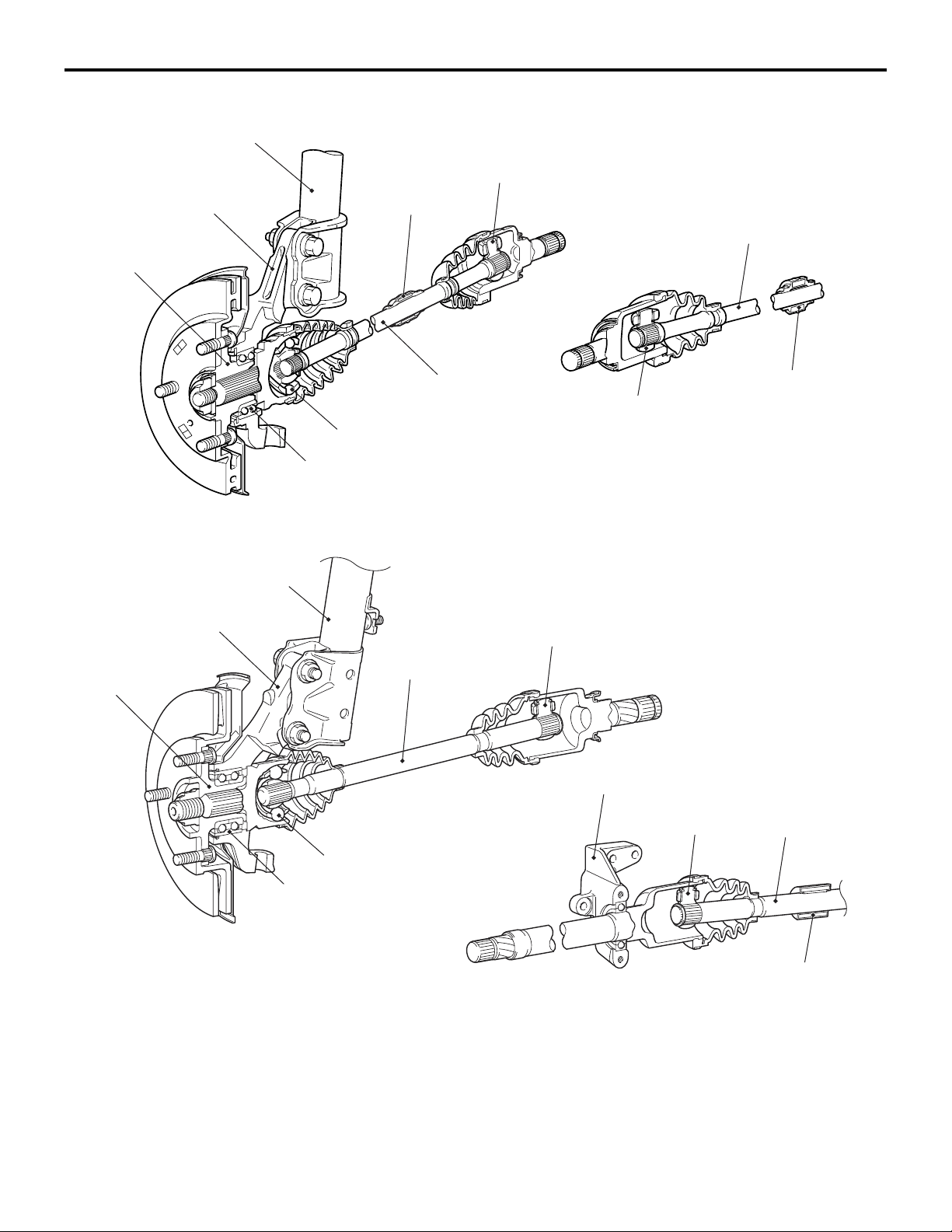
CONSTRUCTION DIAGRAM
FRONT AXLE
GENERAL INFORMATION
26-3
<4A9>
Front hub
<4G1>
Strut assembly
Knuckle
Strut assembly
EBJ
Wheel bearing
TJ (LH) <CVT, M/T (LS)>
ETJ (LH) <M/T (VR)>
Dynamic damper
Driveshaft (LH)
Driveshaft (RH)
TJ (RH) <CVT, M/T (LS)>
ETJ (RH) <M/T (VR)>
Dynamic damper
AC402000
AC403318
AG
Front hub
Knuckle
BJ
Wheel bearing
Driveshaft (LH)
TJ
Bracket assembly
TJ
Driveshaft (RH)
Dynamic damper
AC511705
AC
Page 29
26-4
FRONT AXLE
GENERAL INFORMATION
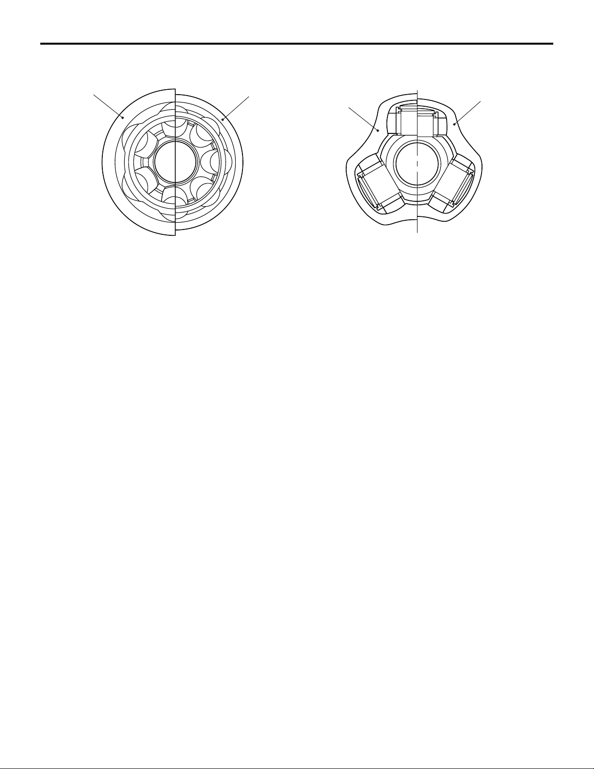
BJ
Comparison between BJ and EBJ
EBJ
Comparison between TJ and ETJ
TJ
ETJ
AC306013AE
Page 30

GROUP 27
REAR AXLE
CONTENTS
GENERAL INFORMATION . . . . . . . . 27-2
Page 31

27-2
REAR AXLE
GENERAL INFORMATION
GENERAL INFORMATION
M2270000100382
The rear axle has the following features:
• The wheel bearing is a unit ball bearing (double-row angular contact ball bearing) for reduced
friction.
• The wheel bearing incorporates magnetic
encoder for wheel speed sensing.
SPECIFICATION
Item Specification
Wheel bearing Type Unit ball bearing (double-row angular
NOTE: The wheel bearing is part of the hub, therefore its size is not listed here.
CONSTRUCTION DIAGRAM
• The rear wheel hub assembly combines the hub,
wheel bearing and oil seal in a single unit for
fewer parts, better durability, improved assembly
precision, and better structural organization.
contact ball bearing)
Rear hub
<4G1> <4A9>
Oil seal
Magnetic encoder
Wheel bearing
Rear hub
Wheel bearing
Oil seal
Magnetic encoder
AC402053AC600026
AC600074
AD
Page 32

GROUP 31
WHEEL AND TYRE
CONTENTS
GENERAL INFORMATION . . . . . . . . 31-2
Page 33

31-2
WHEEL AND TYRE
GENERAL INFORMATION
GENERAL INFORMATION
M2310000100800
The wheels and tyres of the following specifications
have been established.
SPECIFICATIONS
ROAD WHEEL AND TYRE
Item LS VR, VR-X RALLIART
Wheel Type Steel type Aluminium type Aluminium type
Size 14 × 5.5JJ 15 × 6JJ 16 × 6.5JJ
Amount of wheel offset mm46 46 43
PCD mm 100 100 11 4 . 3
Tyre Size 175/65R14 82S 185/55R15 81V 205/45R16 83W
NOTE: PCD indicates the pitch circle diameter of the wheel installation holes.
SPARE WHEEL AND TYRE
Item LS, VR VR-X RALLIART
Spare
wheel
Type Steel type Steel type Steel type
Size 14 × 4T 15 × 4T 15 × 3.5B
Amount of wheel offset mm38 46 40
PCD mm 100 100 11 4 . 3
Spare tyre Size T115/70D14 88M T125/70D15 95M T125/70D15 95M
NOTE: PCD indicates the pitch circle diameter of the wheel installation holes.
Page 34

GROUP 33
FRONT
SUSPENSION
CONTENTS
GENERAL INFORMATION . . . . . . . . 33-2
Page 35

33-2
FRONT SUSPENSION
GENERAL INFORMATION
GENERAL INFORMATION
Newly developed MacPherson strut suspension has
been adopted.
• The steering gear box is installed in the lower
position for better cornering performance.
• The roll centre and the kingpin axle are installed
appropriately for better cornering performance.
• The long stroke strut is adopted for sufficient road
holding quality.
M2330000100824
• High-rigid and light-weight flat crossmember is
adopted for sufficient suspension rigidity.
• The strut coil spring is installed appropriately for
friction reduction and comfortable ride.
• The coil spring of high tension material is adopted
for weight reduction.
• The open-section lower arm is adopted for weight
reduction.
Page 36

CONSTRUCTION DIAGRAM
<4A9>
Coil spring
FRONT SUSPENSION
GENERAL INFORMATION
Strut assembly
Stabilizer bar
33-3
Lower arm
close
section
Lower arm
<4G1>
Ball joint
Coil spring
Front axle No.1 crossmember
(Flat crossmember)
A-point bushing
Lower arm
Strut assembly
Stabilizer bar
AC402422
Lower arm
close
section
AF
AC207732
Lower arm
Ball joint
Front axle No.1 crossmember
(Flat crossmember)
A-point bushing
Lower arm
AC402422
AE
Page 37

33-4
FRONT SUSPENSION
GENERAL INFORMATION
SPECIFICATIONS
SUSPENSION SYSTEM
Item Specification
Suspension type MacPherson strut with coil spring
WHEEL ALIGNMENT
Item Specification
Camber
Caster 4A9 2°35'
4G1 2°40'
Kingpin inclination 13°20'
Toe -i n At the centre of tyre tread mm 0
To e- an gle ( pe r wh ee l) 0°
− 0 °30'
COIL SPRING
<4A9>
Item Specification
Wire diameter mm 12
Average outside diameter mm 133 − 149 − 154
Free length mm CVT 331
5MT 301
<4G1>
Item Specification
Wire diameter mm 13
Average outside diameter mm 133 − 150 − 154
Free length mm 300
Page 38

GROUP 34
REAR SUSPENSION
CONTENTS
GENERAL INFORMATION . . . . . . . . 34-2
Page 39

34-2
REAR SUSPENSION
GENERAL INFORMATION
GENERAL INFORMATION
Newly developed H-shaped torsion beam type suspension has been introduced.
• The coil spring is installed under the rear floor,
the torsion beam and arm assembly is installed in
front of the spare tyre house, and the shock
absorber is installed outside, so that the large
cabin space is achieved.
• The arm bushing with the toe control function is
adopted to optimise the tyre steering angle using
the bushing deflection caused by lateral force
and longitudinal force generated at cornering, so
that the good cornering performance is secured.
CONSTRUCTION DIAGRAM
M2340000100825
• The layout of shock absorber is optimised for
smooth riding.
• Long wheel stroke secures sufficient road holding
quality.
• The hub-integrated unit bearing is adopted for the
wheel bearing for sufficient suspension rigidity
(Refer to GROUP 27, Rear Axle
P.27-2).
• The dumping characteristic of shock absorber
has been changed. <4G1>
• The urethane bump stopper has been adopted to
improve the linearity. <4G1>
• To rs io n b ea m r ig id it y h as b ee n i mp ro v ed < 4G 1>
Shock absorber
Arm bushing
Section A – A
<4G9>
Torsion bar
Torsion beam and arm assembly
Torsion beam and arm assembly
A
A
Coil spring
Section A – A
<4G1>
Torsion beam and arm assembly
AC405533
AD
Page 40

REAR SUSPENSION
GENERAL INFORMATION
SPECIFICATIONS
SUSPENSION SYSTEM
Item Specification
Suspension type To rs ion b ea m sus pe ns io n
WHEEL ALIGNMENT
Item Specification
Camber
Toe -i n At the centre of tyre tread mm 3
To e- an g le ( per w he el ) 0°09'
−1°
COIL SPRING
Item 4A9 4G1
Wire diameter mm 10 11
Average outside diameter mm 75 − 107 − 75 111
34-3
Free length mm 301 283
Page 41

GROUP 35
SERVICE BRAKE
CONTENTS
BASIC BRAKE SYSTEM . . . . . . . . . . . . . . . . . . . . . . . . . . . . . . 35A
ANTI-SKID BRAKE SYSTEM (ABS) . . . . . . . . . . . . . . . . . . . . . 35B
ACTIVE STABILITY CONTROL SYSTEM (ASC). . . . . . . . . . . . 35C
Page 42

GROUP 35A
BASIC BRAKE
SYSTEM
CONTENTS
GENERAL INFORMATION . . . . . . . . 35A-2
CONSTRUCTION DESCRIPTION . . . 35A-5
MASTER CYLINDER . . . . . . . . . . . . . . . . . 35A-5
BRAKE BOOSTER . . . . . . . . . . . . . . . . . . . 35A-5
BRAKE PEDAL . . . . . . . . . . . . . . . . . . . . . . 35A-6
FRONT BRAKE . . . . . . . . . . . . . . . . . . . . . . 35A-7
REAR BRAKE . . . . . . . . . . . . . . . . . . . . . . . 35A-8
Page 43

35A-2
BASIC BRAKE SYSTEM
GENERAL INFORMATION
GENERAL INFORMATION
FEATURES
Brake system with high reliability and durability have
achieved distinguished braking performance.
BRAKING PERFORMANCE
• Brake booster with 9-inch variable amplification
ratio mechanism by which greater braking force
can be obtained with a less pedal pressure has
been installed (with brake assist function).
• 14-inch disc brake is installed on the front
wheels. <LS, VR>
• 15-inch disc brake is installed on the front
wheels. <VR-X, RALLIART Version-R>
• 8-inch leading trailing type drum brake is installed
on the rear wheels. <LS, VR>
• 14-inch disc brake is installed on the rear wheels.
<VR-X, RALLIART Version-R>
STABILITY
• 4-wheel anti-lock braking system (4ABS) is
adopted to prevent slipping caused by the vehicle
wheels locking up, in order to maintain appropri
ate braking distance, and also to maintain vehicle
stability and steering function.
-
M2350000100848
• Electronic brake-force distribution (EBD) is
adopted to maintain the maximum amount of rear
braking force even when the vehicle's load is var
ied.
• Diagonal split (X-type) brake fluid line is adopted.
• Ventilated discs have been adopted to front
brakes to improve anti-fading performance.
• A brake pedal retraction suppression structure
that restrains the retraction of the brake pedal
and reduces the shock to the feet of the driver in
the event of a frontal collision has been adopted.
SERVICEABILITY
• Diagnosis function is adopted for the ABS system
in order to make inspection easier.
• For the front disc brakes, brake disc separated
front hub is adapted to make removal and instal
lation easier.
• ABS-ECU and hydraulic unit have been integrated to make them more compact and lighter.
-
-
Page 44

CONFIGURATION DIAGRAM
<LS, VR>
Brake booster (with variable
boosting mechanism)
Master cylinder
Front disc brake
BASIC BRAKE SYSTEM
GENERAL INFORMATION
Hydraulic unit
(Integrated with ABS-ECU)
35A-3
Rear drum brake
<VR-X, RALLIART Version-R>
Brake booster (with variable
boosting mechanism)
Master cylinder
Front disc brake
Hydraulic unit
(Integrated with ABS-ECU)
Rear disc brake
AC601653
AB
Page 45

35A-4
BASIC BRAKE SYSTEM
GENERAL INFORMATION
SPECIFICATIONS
Item Specifications
Master cylinder Ty pe Ta nd em ty pe
I.D. mm LS, VR 20.6
VR-X 22.2
RALLIART Version-R 23.8
Brake booster Type Vacuum t y p e , s i n g le
Effective dia. of power cylinder mm 230
Boosting ratio LS, VR, VR-X 6.0 (pedal pressure: 116 N)
7.0 (pedal pressure: 159 N)
RALLIART Version-R 6.0 (pedal pressure: 87 N)
7.0 (pedal pressure: 125 N)
Rear wheel hydraulic control method Electronic brake-force
distribution (EBD)
Front brakes Type LS, VR Floating caliper, 1 piston,
ventilated disc (V4-S51)
VR-X, RALLIART Version-R Floating caliper, 1 piston,
ventilated disc (V5-S54)
Disc effective dia. ×
thickness mm
LS, VR 206 × 20
VR-X 226 × 24
Rear disc brakes
<VR-X, RALLIART
Version-R>
Rear drum brakes
<LS, VR>
RALLIART Version-R 232 × 25.8
Cylinder I.D. mm LS, VR 50.8
VR-X, RALLIART Version-R 54.0
Pad thickness mm LS, VR, VR-X 10
RALLIART Version-R 10.5
Clearance adjustment Automatic
Type VR-X Floating caliper, 1 piston,
solid disc (S4-S30P)
RALLIART Version-R Floating caliper, 1 piston,
solid disc (S4-S34P)
Disc effective dia. ×
thickness mm
Cylinder I.D. mm VR-X 30.2
Pad thickness mm VR-X 9.5
Clearance adjustment Automatic
Type Leading trailing drum
Drum I.D. mm 203
Cylinder I.D. mm 19.0
Lining thickness mm 4.0
VR-X 224 × 10
RALLIART Version-R 200.6 × 10
RALLIART Version-R 34.0
RALLIART Version-R 10.0
Clearance adjustment Automatic
Brake fluid DOT3 or DOT4
Page 46

BASIC BRAKE SYSTEM
CONSTRUCTION DESCRIPTION
CONSTRUCTION DESCRIPTION
35A-5
MASTER CYLINDER
M2350001000509
Reserve tank
Master cylinder
The master cylinder is a tandem-type, with a structure that emphasizes safety.
Secondary piston
BRAKE BOOSTER
Diaphragm
Primary piston
AC505737
M2350002000632
AB
Push rod
Booster return spring
9-inch brake booster has been installed. The brake
booster employs a variable amplification ratio mech
anism that varies amplifications ratios so that even
small pedal force can provide great breaking force.
Reaction disc
Operating rod
AC505736
AB
-
Page 47

35A-6
n
BRAKE PEDAL
BASIC BRAKE SYSTEM
CONSTRUCTION DESCRIPTION
M2350007000154
Collision load
Reinforced bracket
After collision
Fixed bolt
Reinforced bracket
Retreat locus of brake pedal during collision
Before collision
AC207292
Deck crossmember
Stopper plate
Brake booster
The brake pedal rearward displacement prevention
mechanism has been adopted in order to reduce the
driverís leg and foot injury during frontal collision.
Brake pedal position before collision
Brake pedal position after collision
(Conventional)
Brake pedal position after collision
(Brake pedal rearward displacement preventio
mechanism operated)
AC207291
AC207749
AE
The brake booster is forced to move backward
according to retreating engine body during frontal
collision and then the reinforced bracket is released
from the stopper plate. After released, the reinforced
bracket is forced to move backward and downward
by guiding the rear end of the reinforced bracket
along the stopper plate slope and it prevent the back
ward and upward displacement of the brake pedal.
-
Page 48

FRONT BRAKE
14-inch disc brake
<LS, VR>
BASIC BRAKE SYSTEM
CONSTRUCTION DESCRIPTION
M2350003000538
Conventional structure
Caliper support
bracket
35A-7
15-inch disc brake
<VR-X, RALLIART Version-R>
• Ventilated disc brake (V4−S51 or V5−S54) is
installed.
• The calliper support bracket integrated with the
knuckle has been installed, achieving weight
reduction and optimising it for brake perform
ance.
• Audible wear indicator that informs the driver of
wear limit is installed to the inner brake pad.
(Only left side)
DISC BRAKE DESIGNATION
Knuckle
When new When worn
Pad
Wear indicator
Brake disk
AC403189
AE
No. Item Content
1 Brake disc type V: Ventilated
2 Brake size
-
(Minimum applicable
4: 14-inch
5: 15-inch
disc wheel)
3 No. of piston S: 1piston (floating type)
4 Piston size (rounded
to nearest integer)
30: φ 30 mm
34: φ 34 mm
51: φ 51 mm
54: φ 54 mm
S 4 - S 30 P
1 2 3 4 5
AC403539
5 Parking brake
mechanism
P: Set
Page 49

35A-8
REAR BRAKE
<8-inch leading trailing type drum brake> <14-inch disc brake>
BASIC BRAKE SYSTEM
CONSTRUCTION DESCRIPTION
M2350004000531
• 8-inch leading trailing type drum brake, which
assures stable braking force during forward or
rearward movement, has been installed. <LS,
VR>
• Disc brake (S4-S30P) has been installed. <VR-X,
RALLIART Version-R>
AC403060
AD
• An audible wear indicator that informs the driver
of application limit has been installed to the left
brake pad. <VR-X, RALLIART Version-R>
NOTE: For disc brake designation, refer to P.35A-7.
Page 50

GROUP 35B
ANTI-SKID BRAKE
SYSTEM (ABS)
CONTENTS
GENERAL INFORMATION . . . . . . . . 35B-2 CONSTRUCTION DESCRIPTION . . . 35B-6
SENSORS . . . . . . . . . . . . . . . . . . . . . . . . . . 35B-6
ABS-ECU. . . . . . . . . . . . . . . . . . . . . . . . . . . 35B-6
Page 51

35B-2
ANTI-SKID BRAKE SYSTEM (ABS)
GENERAL INFORMATION
GENERAL INFORMATION
FEATURES
The ABS ensures directional stability and controllability during hard braking.
For vehicles with this type of ABS, 4 sensors (4
channels) are installed on front and rear wheels
allowing independent left and right control.
The system has the following features:
• EBD (Electronic Brake-force Distribution system)
control has been added to provide the ideal brak
ing force for the rear wheels.
• Magnetic encoder for wheel speed detection has
been installed as a sensing device instead of the
rotor.
• For wiring harness saving and secure data communication, CAN* bus has been adopted as a
tool of communication with another ECU.
NOTE: *: For more information about CAN (Controller Area Network), refer to Group 54C, General Information P.54C-2.
M2351000100409
EBD CONTROL
In ABS, electronic control is used so the rear wheel
brake hydraulic pressure during braking is regulated
by rear wheel control solenoid valves in accordance
with the vehicle's rate of deceleration, and the front
and rear wheel slippage which are calculated from
the signals received from the various wheel speed
sensors. EBD control provides a high level of control
-
for both vehicle braking force and vehicle stability.
The system has the following features:
• Because the system provides the optimum rear
wheel braking force regardless of vehicle load
condition and the condition of the road surface,
the system reduces the required pedal depres
sion force, particularly when the vehicle is heavily
loaded or driven on road surfaces with high fric
tional coefficients.
• Because the duty placed on the front brakes is
reduced, the increase in pad temperature can be
controlled during brakes application to improve
the wear resistance characteristics of the pad.
• Control valves such as the proportioning valve
are not required.
-
-
SPECIFICATIONS
Item Specification
ABS control method 4-sensor, 4-channel
Wheel speed
sensor
Magnetic encoder Front 86 (N pole:43 S pole:43)
Rear 86 (N pole:43 S pole:43)
Type Semiconductor
Page 52

CONSTRUCTION DIAGRAM
ANTI-SKID BRAKE SYSTEM (ABS)
GENERAL INFORMATION
35B-3
6
3, 7
4
5
2
1
1
AC400129
AB
Name of part Number Outline of function
Sensor Wheel speed sensor 1 Sends alternating current signals at frequencies which are
proportional to the rotation speeds of each wheel to the
ABS-ECU.
Stop lamp switch 2 Sends a signal to the ABS-ECU to indicate whether the
brake pedal is depressed or not.
Actuator Hydraulic unit 3 Drives the solenoid valves according to signals from the
ABS-ECU in order to control the brake hydraulic pressure
for each wheel.
ABS warning lamp 4 Illuminates in response to signals from the ABS-ECU
when a problem develops in the system.
Brake warning lamp 5 Illuminates in response to signals from the ABS-ECU
when a problem develops in the EBD system.
Diagnosis connector 6 Outputs the diagnosis codes and allows communication
with the M.U.T.-III.
ABS-ECU 7 Controls actuators (described above) based on the signals
coming from each sensor.
Controls the self-diagnosis and fail-safe functions.
Controls the diagnostic function (M.U.T.-III compatible).
Page 53

35B-4
ANTI-SKID BRAKE SYSTEM (ABS)
GENERAL INFORMATION
SYSTEM CONFIGURATION DIAGRAM
Front-left wheel speed sensor
Rear-left wheel speed sensor
Rear-right wheel speed sensor
Front-right wheel speed sensor
Stop lamp switch
ABS-ECU power supply
Front-right wheel (FR)
ABS-ECU
Engine-CVT-ECU
Front-right solenoid valve (out)
Front-right solenoid valve (in)
Front-left solenoid valve (out)
Front-left solenoid valve (in)
Rear-right solenoid valve (out)
Rear-right solenoid valve (in)
Rear-left solenoid valve (out)
Rear-left solenoid valve (in)
Brake warning lamp
ABS warning lamp
Diagnosis connector
Stop lamp switch
Rear-right wheel (RR)
Rear-right
wheel speed
sensor
Front right
wheel speed
sensor
Hydraulic
unit
Front-left
wheel speed
sensor
Front-left wheel (FL)
NOTE: Broken lines show CAN-bus line.
Rear-left
wheel speed
sensor
Rear-left wheel (RL)
AC314168
AB
Page 54

ANTI-SKID BRAKE SYSTEM (ABS)
GENERAL INFORMATION
ABS ELECTRICAL CIRCUIT DIAGRAM
35B-5
Fusible
link No.1
J/B
(Fuse)
No.42
15A
Stop lamp
switch
Off
On
Ignition
switch (IG1)
No.40
7.5A
Fusible
link No.5
ABS-ECU
Motor power
supply
Fusible
link No.3
Solenoid valve
power supply
Fusible
link No.6
J/B
(Fuse)
No.33
15A
Hydraulic unit
Solenoid valve
Motor power
supply
Front wheel speed
sensor
(rear, left)
Rear wheel speed
sensor
(rear, right)(front, right)(front, left)
Engine-CVT-ECU
J/C
(CAN2)
J/C
(CAN1)
Combination meter
(ABS warning lamp and
brake warning lamp)
Diagnosis connector
AC314169
AB
Page 55

35B-6
ANTI-SKID BRAKE SYSTEM (ABS)
CONSTRUCTION DESCRIPTION
CONSTRUCTION DESCRIPTION
SENSORS
M2351001000427
WHEEL SPEED SENSORS AND MAGNETIC ENCODER FOR WHEEL SPEED
DETECTION
Front Rear <Drum> Rear <Disc>
Front wheel speed sensor
Encoder for wheel
speed detection
Wheel speed sensor is a kind of a pulse generator
consisted of a magnetic encoder (a plate on which
north and south pole sides of the magnet are
arranged alternately) for wheel speed detection
which rotates at the same speed of the wheels, and a
speed sensor (semiconductor sensor), sends fre
quency pulse signals in proportion to wheel speed.
Front wheel speed sensor consists of a front wheel
speed sensor secured on the knuckle, and a mag
netic encoder for wheel speed detection fitted to the
inside of the front wheel bearing. Rear wheel speed
sensor consists of a rear wheel speed sensor
secured on the rear hub, and a magnetic encoder for
wheel speed detection press fitted to the rear hub
inner ring.
Rear wheel speed sensor
Encoder for wheel
speed detection
-
-
Rear wheel speed sensor
Encoder for wheel
speed detection
ABS-ECU
• By integrating ABS-ECU into the hydraulic unit,
no more wiring harnesses for sending signal that
operates the solenoid valve and pump motor is
required, assuring higher reliability.
• Self-diagnostic programs and memory functions
are integrated into ABS-ECU. If any malfunction
is detected by the self-diagnostic function,
ABS-ECU activates a fail-safe function and illuminates ABS warning lamp and brake warning
*
.
lamp
NOTE: *: ABS-ECU illuminates the brake warning
lamp as EBD control warning lamp.
• ABS-ECU detects vehicle speed from the wheel
speed sensor signal, recognizes the wheel rota
tion, estimates the wheel slip condition based on
the preprogrammed algorithm, and then controls
the solenoid valve in the hydraulic unit so that the
wheels do not lock.
AC601358
M2351003000252
AB
-
ABS FLUID PRESSURE CONTROL
FOUR-WHEEL CONTROL
ABS fluid pressure is controlled independently for
four wheels.
Page 56

ANTI-SKID BRAKE SYSTEM (ABS)
CONSTRUCTION DESCRIPTION
EBD FLUID PRESSURE CONTROL
Ideal distribution curve when
seated by fixed persons
Rear braking force
Ideal distribution curve when seated by one persons
EBD operating conceptual design
Braking force distribution
by EBD control
Braking force distribution curve
by the existing proportioning valve
Front braking force
35B-7
Braking Force
Improved
EBD control is activated within the lower slip ratio
area where ABS is disabled. ABS-ECU calculates
vehicle deceleration and slip amount of the four
wheels based on the wheel speed sensor signal. If
the rear wheel speed differs from the vehicle speed
by a certain level or more, ABS-ECU boost, holds,
and depressurises the rear wheel control solenoid
valve in the hydraulic unit, and then adjusts rear
wheel brake fluid pressure fairly close to an ideal dis
tribution curve.
INITIAL CHECK
ABS-ECU internally activates the self-diagnostic
function. ABS-ECU illuminates ABS warning lamp for
3 seconds (including the initial check)
*
after the ignition switch is turned ON. If any malfunction is
detected, ABS-ECU continues illuminating ABS
warning lamp and disables ABS control.
NOTE: *: ABS warning lamp may stay ON after the
ignition switch is turned ON until the startup vehicle
speed reaches approximately 10km/h. As far as
ABS-ECU memorizes any diagnosis code related to
the wheel speed sensor malfunction recorded during
previous ignition ON status, ABS-ECU continues illu
minating ABS warning lamp until it verifies that the
malfunction for that code is resolved (Startup check).
STARTUP CHECK
When the startup vehicle speed reaches approximately 10 km/h, ABS-ECU performs the following
checks.
• Motor, solenoid valve check (only in initial startup*)
AC208548
Operates the motor relay in ECU and checks the
pump motor operation. At the same time,
ABS-ECU sequentially energizes each solenoid
valve in a very short period and checks the valve
operation.
NOTE: *: Initial startup indicates a first startup after
the system has started.
• Wheel speed sensor check
-
ABS-ECU checks for any wheels that have not
received wheel speed sensor signal from the
startup.
CONSTANT CHECK
ABS-ECU constantly checks the following item.
• ABS-ECU
Performs self-diagnosis in ECU.
• ECU power supply
Checks if ECU power supply voltage reaches within
the operational range.
• Wheel speed sensor
• Monitors the output voltage of the sensor sig-
nal wiring harness and checks for abnormal
output voltage (open/short circuit).
-
• Checks for any wheels that do not send pulse
signal while the vehicle is in motion.
• Checks if wheel speed which is abnormally
higher or lower than the vehicle speed is
input.
• Pump motor and solenoid valve
Checks that ABS-ECU output signal and the operat-
ing condition of the pump motor and solenoid
valve agree with each other.
AB
Page 57

35B-8
ANTI-SKID BRAKE SYSTEM (ABS)
CONSTRUCTION DESCRIPTION
CAN COMMUNICATION
ABS-ECU outputs ABS warning lamp and EBD
*
warning lamp
combination meter through CAN communication.
NOTE: *: ABS-ECU illuminates the brake warning
lamp as EBD control warning lamp.
Diagnosis
code No.
C1200 Open or short
C1201 Wheel speed
C1205 Open or short
C1206 Wheel speed
C1210 Open or short
illumination request signals to the
Item Action during fail-safe operation
ABS control EBD control CAN output Brake
Prohibits
circuit in wheel
speed sensor (FR)
sensor (FR) system
circuit in wheel
speed sensor (FL)
sensor (FL) system
circuit in wheel
speed sensor (RR)
control of
malfunctioning
wheel.
Prohibits all
wheel control
after control is
completed.
FAIL - SAFE FUNCTION
If any malfunction is detected by the self-diagnostic
function, ABS-ECU illuminates ABS warning lamp
and brake warning lamp
EBD as shown in the following table.
NOTE: *: ABS-ECU illuminates the brake warning
lamp as EBD control warning lamp.
Two or less
wheel
Abnormal:
Enabled
Three or
more wheels
Abnormal:
Prohibits
Output
permitted
*
, and it controls ABS and
ABS
warning
lamp
Two or less
wheel
Abnormal:
OFF
Three or
more
wheels
Abnormal:
ON
warning
lamp
ON
C1211 Wheel speed
sensor (RR)
system
C1215 Open or short
circuit in wheel
speed sensor (RL)
C1216 Wheel speed
sensor (RL) system
C1225 Wheel speed
sensor malfunction
System
shut-down
System
shut-down
Output
permitted
ON ON
Page 58

ANTI-SKID BRAKE SYSTEM (ABS)
CONSTRUCTION DESCRIPTION
35B-9
Diagnosis
code No.
C1226 Control solenoid
C1231 Control solenoid
C1236 Control solenoid
C1241 Control solenoid
C1246 Control solenoid
Item Action during fail-safe operation
valve (FR) pressure
holding system
valve (FR)
decompressing
system
valve (FL) pressure
holding system
valve (FL) pressure
reducing system
valve (RR)
pressure holding
system
ABS control EBD control CAN output Brake
warning
lamp
Prohibited Prohibited Output
permitted
ON ON
ABS
warning
lamp
C1251 Control solenoid
valve (RR)
pressure reducing
system
C1256 Control solenoid
valve (RL) pressure
holding system
C1261 Control solenoid
valve (RL)
decompressing
system
C1266 Motor system
(stuck)
C1273 Motor relay stuck
off
C1274 Motor relay stuck
on
C1276 Valv e r elay system System
C1278 Valv e r elay system
stuck off
C1279 Valv e r elay system
stuck on
Prohibited Enabled Output
shut-down
System
shut-down
Prohibited Enabled Output
System
shut-down
System
shut-down
permitted
Output
permitted
Output
permitted
permitted
OFF ON
ON ON
ON ON
OFF ON
Page 59

35B-10
ANTI-SKID BRAKE SYSTEM (ABS)
CONSTRUCTION DESCRIPTION
Diagnosis
code No.
C1607 Trouble in
C1860 High voltage at
C1861 Low voltage at
U1073 Trouble in CAN bus
Item Action during fail-safe operation
ABS-ECU
Trouble in
ABS-ECU (CAN
Initialisation
malfunction)
ABS-ECU power
supply
ABS-ECU power
supply
system
ABS control EBD control CAN output Brake
warning
lamp
System
shut-down
Enabled Enabled Output
Wait Wait Output
Wait Wait Output
Enabled Enabled Output
System
shut-down
Output
permitted
(Output may
be
impossible).
impossible
permitted
permitted
impossible
ON ON
*
ON
ON ON
ON ON
*
ON
ABS
warning
lamp
*
ON
*
ON
NOTE: .
*
•
: If any trouble occurs in CAN communication,
the brake warning lamp and ABS warning lamp
on the combination meter turns ON.
•
Prohibit: Any controls are not performed until the
ignition switch is turned OFF.
•
System shut-down: Control will be disabled until
valve power supply is turned off, and then ignition
switch is turned to the OFF position.
•
Wait: ABS control is restarted when the normal
condition is resumed even though the ignition
switch is not turned OFF.
DIAGNOSTIC FUNCTION
ABS-ECU has the following functions for easier system checks. The following items can be diagnosed
using the M.U.T.-III (ABS warning lamp illuminates
and ABS control is prohibited while the ABS-ECU
communicates with the M.U.T.-III).
• Diagnosis code set
• Service data output
• Actuator test
DIAGNOSIS CODE SET
There are 28 diagnostic items. Since all the diagnostic results are recorded in volatile memory (EEPROM*), they are stored in the memory even though
the battery terminals are disconnected.
NOTE: .
•
*EEPROM (Electrical Erasable &;Programmable
ROM): Special type of memory that can be pro
grammed or erased electrically
•
For each diagnostic item, refer to Fail-safe Function.
-
Page 60

ANTI-SKID BRAKE SYSTEM (ABS)
CONSTRUCTION DESCRIPTION
35B-11
SERVICE DATA OUTPUT
The following items of the ECU input data can be
read using M.U.T.-III.
Item No. Check item Check condition Normal condition
01 FR wheel speed sensor Perform a test run of the vehicle. Speedometer display and
02 FL wheel speed sensor
03 RR wheel speed sensor
04 RL wheel speed sensor
05 Power supply voltage Always 10 V or more
06 Stop lamp switch The brake pedal is depressed ON
The brake pedal is released. OFF
07 Valve relay When ABS is operating ON
When ABS is not operating OFF
10 FL inlet valve When ABS is operating ON
When ABS is not operating OFF
11 FL outlet valve When ABS is operating ON
M.U.T.-III display almost agree
with each other.
When ABS is not operating OFF
12 FR inlet valve When ABS is operating ON
When ABS is not operating OFF
13 FR outlet valve When ABS is operating ON
When ABS is not operating OFF
14 RL inlet valve When ABS is operating ON
When ABS is not operating OFF
15 RL outlet valve When ABS is operating ON
When ABS is not operating OFF
16 RR inlet valve When ABS is operating ON
When ABS is not operating OFF
17 RR outlet valve When ABS is operating ON
When ABS is not operating OFF
20 Pump motor When ABS is operating ON
When ABS is not operating OFF
Page 61

35B-12
ANTI-SKID BRAKE SYSTEM (ABS)
CONSTRUCTION DESCRIPTION
ACTUATOR TEST
Activation Pattern
Solenoid
valve
Pump
motor
A
B
C
On
Off
Note
Hydraulic pressure increases
A:
Hydraulic pressure holds
B:
Hydraulic pressure decreases
C:
Start of
activation
1 s
2 s
End of
activation
AC300188
AD
NOTE: .
•
When ABS-ECU is disabled, the actuator test
cannot be performed.
•
The actuator test can be performed only when
the vehicle is stationary. When the vehicle speed
reaches 10km/h, the forcible actuator operation is
disabled.
•
During actuator test, the ABS warning lamp illuminates, and ABS control is prohibited.
Item No. Check item Drive Contents
01 Solenoid valve for
front-right wheel
02 Solenoid valve for
front-left wheel
Solenoid valves
and pump motor in
the hydraulic unit
(simple inspection
mode)
03 Solenoid valve for
rear-right wheel
04 Solenoid valve for
rear-left wheel
The M.U.T.-III can be used to force-drive all solenoid
valves and the pump motor.
Page 62

GROUP 36
PARKING BRAKES
CONTENTS
GENERAL INFORMATION . . . . . . . . 36-2
STRUCTURAL DESCRIPTION
<CVT> . . . . . . . . . . . . . . . . . . . . . . . . 36-4
OPERATIONAL DESCRIPTION
<CVT> . . . . . . . . . . . . . . . . . . . . . . . . . 36-5
Page 63

36-2
PARKI N G B R A K E S
GENERAL INFORMATION
GENERAL INFORMATION
<CVT>
Employment of the parking brake pedal clears front
centre space to allow a walk through design.
PUSH-ON/PUSH-RELEASE type pedal has been
installed for easier operation.
Parking brake pedal assembly
M2360000100656
The parking brake pedal retreat suppression mechanism that restraints the retraction of the brake pedal
during collision has been adopted in order to reduce
the shock to the driver's feet. The mechanism of the
parking brake pedal is basically the same as that of
the brake pedal.
NOTE: For more information about brake pedal
retreat suppression mechanism, refer to GROUP
35A, Brake Pedal
P.35A-6.
Parking brake cable cover
<LS>
<VR-X>
AC506311
AC
Page 64

PARKING BRAKES
GENERAL INFORMATION
36-3
<Parking brake pedal retreat suppression mechanism>
Parking brake pedal
bracket
Collision load
Brake pedal position
before collision
AC207360
After collision
Fixed bolt
Deck
crossmember
Retreat trajectory of brake pedal
during collision
Brake pedal surface position after collision
(Brake pedal retreat suppression
mechanism operated)
Parking brake pedal bracket
Before collision
AC207354
AC207757
AB
<M/T>
The parking brake is of a mechanical rear-wheel acting type, and its operation utilises a parking brake
lever.
<RALLIART Version-R>
Parking brake lever (Leather grip)
Parking brake cable
<LS, VR>
Parking brake lever
Parking brake cable
AC601652
AB
Page 65

36-4
Return spring
PARKI N G B R A K E S
STRUCTURAL DESCRIPTION <CVT>
STRUCTURAL DESCRIPTION <CVT>
M2360000200192
The parking brake pedal assembly consists of the
parking brake pedal, sector, release lever, pawl
return spring, pawl, and return spring. The sector is
secured to the parking brake pedal bracket body.
The pawl and release lever are fixed to the pin axle
by the section with an oblong hole. The pawl and
release lever are connected by the pawl returning
spring, and move together with the pedal.
Pawl
Sector
Release lever
Pawl return spring
AC207357
AB
Page 66

PARKI N G B R A K E S
OPERATIONAL DESCRIPTION <CVT>
OPERATIONAL DESCRIPTION <CVT>
PARKI N G B RA K E P ED AL OP E RAT I ON
OPERATION WHEN PEDAL IS
DEPRESSED
Spring force
Sector
Pawl axle
Release lever
Pawl
Pawl return spring
AC405464
When the parking brake is released, the pawl
receives the left-rotation force (the direction of
engagement) around the pawl axis from the pawl
return spring. Then, depressing the pedal engages
the pawl and sector, releasing a clicking sound.
AB
36-5
M2360000300207
OPERATION AFTER PEDAL IS
DEPRESSED
Contact point
of release lever
and pawl
Release lever
rotates
AC405465
Depressing the pedal and removing one's foot
causes the pawl axis to slide the section with an
oblong hole from the repulsive force of the cable.
Then, the release lever affixed to the pawl axis is
pushed by the pawl and rotates, the pawl return
spring position is inverted, and right-rotation force (in
the release direction) is applied to the pawl. At this
time, the engagement force of the pawl and sector
prevents release.
AB
OPERATION WHEN PEDAL IS
DEPRESSED
Disengaged
AC405466
Depressing the pedal again for release disengages
it, rotating the pawl from the spring force and releas
ing the lock.
AB
-
Page 67

36-6
OPERATION WHEN PEDAL IS
RETURNED
PARKI N G B R A K E S
OPERATIONAL DESCRIPTION <CVT>
Lever
returning
part
AC405467
AB
When returning the pedal, the release lever returns
to the starting position from the lever returning sec
tion as the spring position is inverted, causing the
pawl to return to the position of release for the park
ing break.
-
-
Page 68

GROUP 12
ENGINE
LUBRICATION
CONTENTS
GENERAL INFORMATION . . . . . . . . 12-2
OIL PUMP<4A9> . . . . . . . . . . . . . . . . 12-4
RELIEF VALVE<4A9> . . . . . . . . . . . . 12-4
OIL SCREEN<4A9> . . . . . . . . . . . . . . 12-5
OIL FILTER<4A9> . . . . . . . . . . . . . . . 12-5
OIL PAN<4A9> . . . . . . . . . . . . . . . . . . 12-6
OIL LEVEL GAUGE, OIL FILLER CAP,
OIL DRAIN PLUG<4A9> . . . . . . . . . . 12-6
OIL COOLER<4G1> . . . . . . . . . . . . . . 12-7
Page 69

12-2
ENGINE LUBRICATION
GENERAL INFORMATION
GENERAL INFORMATION
LUBRICATION SYSTEM SCHEMATIC<4A9>
M2120000100175
Oil screen
Oil pump
Relief valve
Oil pressure switch
Cylinder head
oil passage
No.1 Camshaft
journal
Intake camshaft
journal
Timing chain case
oil passage
Cylinder block
oil passage(right side)
Oil filter
Cylinder block
oil passage
(main gallery)
Crankshaft
journal
Crankshaft
pin
Exhaust camshaft
journal
The lubrication system of the 4A9 engine has a full
pressure delivery system and a full flow oil filtering
system. The oil stored in the oil pan is pumped
up/out by the oil pump. After the relief valve regulates the oil pressure, the oil is delivered to the cylinder block through the oil filter, the oil passage of the
cylinder block and the each journal of the crankshaft.
AK402024
AC
The oil delivered to the each journal of the crankshaft
is supplied to the pin through the inner passage of
the crankshaft.
The oil delivered to the cylinder head is supplied to
the each journal of the camshaft through the cylinder
head.
Page 70

ENGINE LUBRICATION
GENERAL INFORMATION
LUBRICATION SYSTEM SCHEMATIC<4G1>
12-3
Oil screen
Oil pump
Lash adjuster
Cam
Relief valve
Turbo charger
Cylinder head
oil passage
No.1 Camshaft
journal
Intake camshaft
journal
Oil pan
Oil cooler
Oil filter
Cylinder block
oil passage
(main gallery)
Crankshaft
journal
Crankshaft pin
Exhaust camshaft
journal
Oil pressure switch
Oil jet
Piston
AK402151
AC
To correspond with the improved engine output performance by employing the turbocharger, the oil
cooler and the oil jet are used for 4GI engine.
Page 71

12-4
ENGINE LUBRICATION
OIL PUMP<4A9>
OIL PUMP<4A9>
M2120002000044
A
A
The oil pump is of a cycloid type, directly driven by
the crankshaft.
Specifically, oil is sucked into the expanding space
and is pushed out from the shrinking space.
Timing chain case
Machine screw
Cover
On the cycloid oil pump, as the inner rotor is rotated
by the crankshaft, the outer rotor also rotates. The
resultant change in spatial volumes between the
rotors generates pumping action.
Item Specification
Type Cycloid pump
No. of lobes Inner rotor 10
Outer rotor 11
A-A
Oil seal
Oil pump
inner rotor
Oil pump
outer rotor
AK305367
AB
Displacement L/min(6,000 r/min.) 35
RELIEF VALVE<4A9>
A
A
The relief valve is of a plunger type. The valve regulates the maximum pressure of lubrication oil being
sent to the engine.
When the pressure of oil from the oil pump exceeds
the specified value, the valve opens to relieve the
excess flow.
The excess oil is returned to the suction side of the
oil pump.
A-A
Timing chain case
Relief plunger
Relief spring
Plug
AK305369
M2120003000047
AB
Page 72

ENGINE LUBRICATION
OIL SCREEN<4A9>
Timing chain case
OIL SCREEN<4A9>
The oil screen is located in the position with the least
disturbance to the oil suction volume that results
from oil level variation in the oil pan while the vehicle
is driven.
12-5
M2120004000039
Oil screen
Oil filter
Oil pan
AK305372
Oil filter
bracket
Oil filter
AK401817
AB
OIL FILTER<4A9>
The oil filter is installed to the oil filter bracket
attached to the cylinder block.
Item Specification
Filtering method Full-flow filtering, Paper
Filtration area cm
Rated flow L/min. 25
AE
M2120005000032
element
2
750
Element
AK305373
AB
Page 73

12-6
ENGINE LUBRICATION
OIL PAN<4A9>
OIL PAN<4A9>
M2120006000035
Oil drain plug
installation side
The oil pan, located below the engine, is made of
sheet metal.
OIL LEVEL GAUGE, OIL FILLER CAP, OIL DRAIN
PLUG<4A9>
Oil level gauge
Oil filler cap
AK305374
AB
M2120007000038
Oil drain plug
The oil level gauge, oil filler cap, and oil drain plug
are all located in the front of the engine for excellent
serviceability.
AK402349
AC
Page 74

Coolant inlet
(from throttle body)
ENGINE LUBRICATION
OIL COOLER<4G1>
OIL COOLER<4G1>
Coolant outlet
(to water inlet pipe)
To cylinder block
Oil inlet
12-7
M2120008000020
Oil cooler bolt
From oil filter
An oil cooler is used for the vehicle with a turbocharger to improve the performance of cooling lubricant.
Oil cooler
Oil outlet
AK402142
AC
By circulating the coolant and the oil within the oil
cooler, heat is exchanged and the oil is cooled.
Page 75

GROUP 16
ENGINE
ELECTRICAL
CONTENTS
GENERAL INFORMATION . . . . . . . . 16-2
Page 76

16-2
ENGINE ELECTRICAL
GENERAL INFORMATION
GENERAL INFORMATION
The electronic device is basically the same as that in
the conventional 4G1 engine.
The employed alternator is a lightweight type in
which the electronic voltage regulator for detecting
the battery voltage is built.
M2160000100038
The employed starter motor is a small planetary gear
reduction drive type.
The employed spark plug is a long reach type with
iridium.
The employed ignition coil is a plug top type in which
the powertrain per cylinder is built.
Page 77

GROUP 00
GENERAL
CONTENTS
HOW TO USE THIS MANUAL. . . . . . 00-2
TARGETS OF DEVELOPMENT . . . . 00-2
PRODUCT FEATURES . . . . . . . . . . . 00-3
TECHNICAL FEATURES. . . . . . . . . . 00-4
EXTERIOR . . . . . . . . . . . . . . . . . . . . . . . . . 00-4
INTERIOR . . . . . . . . . . . . . . . . . . . . . . . . . . 00-6
SPACIOUS CABIN . . . . . . . . . . . . . . . . . . . 00-8
ENGINE . . . . . . . . . . . . . . . . . . . . . . . . . . . 00-9
TRANSMISSION. . . . . . . . . . . . . . . . . . . . . 00-10
SUSPENSION. . . . . . . . . . . . . . . . . . . . . . . 00-14
BRAKE . . . . . . . . . . . . . . . . . . . . . . . . . . . . 00-15
STEERING . . . . . . . . . . . . . . . . . . . . . . . . . 00-18
ACTIVE SAFETY. . . . . . . . . . . . . . . . . . . . . 00-19
PASSIVE SAFETY . . . . . . . . . . . . . . . . . . . 00-24
EQUIPMENTS. . . . . . . . . . . . . . . . . . . . . . . 00-27
ENVIRONMENTAL PROTECTION . . . . . . . 00-28
SERVICEABILITY AND RELIABILITY . . . . 00-28
VEHICLE IDENTIFICATION . . . . . . . . 00-30
MAJOR SPECIFICATIONS . . . . . . . . 00-31
<CVT> . . . . . . . . . . . . . . . . . . . . . . . . . . . . . 00-31
<M/T> . . . . . . . . . . . . . . . . . . . . . . . . . . . . . 00-32
Page 78

00-2
HOW TO USE THIS MANUAL
HOW TO USE THIS MANUAL
MODEL INDICATIONS
The following abbreviations are used in this manual
for identification of model types.
DOHC. Indicates an engine with the double over-
head camshaft.
MIVEC. Indicates Mitsubishi innovative valve timing
electronic control system.
MPI. Indicates the multipoint injection.
M/T. Indicates the manual transmission.
CVT. Indicates the continuously variable transmis-
sion.
A/C. Indicates the air conditioner.
TARGETS OF DEVELOPMENT
EXCEPT RALLIART Version-R
The New COLT featuring "exciting feeling and freedom" has been developed for realising "safety, running, quality" and "free-to-select enjoyment" as well
as "true convenience and economical efficiency."
That makes NEW COLT a new generation compact
car.
GENERAL
M2000029000628
M2000004001066
RALLIART Version-R
This "COLT RALLIART Version-R" has been developed as a hot version in which the Mitsubishi Motors'
concept "Sporty
In the midst of this recent wave of the sport model
launches in the compact car class, COLT RALLIART
Version-R has acquired users of the competitors and
the younger generation, and has improved the over
all image of the COLT series by appealing to the
sport-oriented users as the only high-powered turbo
charger vehicle in the class.
−DNA" was further refined.
-
-
Page 79

GENERAL
PRODUCT FEATURES
PRODUCT FEATURES
<Except RALLIART Version-R>
• COLT has been equipped with the new 1,500 mL
aluminium die-cast engine (4A9-engine) for fur
ther refinements of comfort driving, excellent
power performance, fuel economy, and ecology
performance.
<RALLIART Version-R>
• The body and suspension of COLT RALLIART
Version-R have been thoroughly tuned to
increase the 4G1-engine output which enables
dynamic driving.
• The robust image suited for the dynamic driving
has been adopted for the appearance.
SPORTY AND STYLISH DESIGN
• Bucket-like front seats <Except RALLIART Version-R>
• Sport seats exclusive to the models with turbocharger <RALLIART Version-R>
• 15-inch aluminium wheel <VR-X>
• High-contrast combination meter <Except RALLI-
ART Version-R, LS, VR-X (M/T) >
• Robust appearance by new shaped front bumper
adaptation and rear bumper change <RALLIART
Version-R>
• Black overfender <RALLIART Version-R>
• 16-inch aluminium wheel <RALLIART Version-R>
ACTIVE DRIVING AND HIGH QUALITY
• For 4A9-engine, the aluminium die-cast cylinder
-
block has been installed for weight reduction of
the vehicle. <Except RALLIART Version-R>
• For 4G1-engine, turbo-charger model has been
introduced to increase output and torque,
enhancing sporty image. <RALLIART Version-R>
• Sporty driving has been ensured by the
"GETRAG" 5-speed manual transmission (floor
shift). <M/T>
• The suspension has been tuned to improve cornering and stability at high speed. <RALLIART
Version-R>
• A strut tower bar has been adopted to improve
the body rigidity. <RALLIART Version-R>
• Electric power steering system has been
improved and EPS-ECU has been additionally
equipped with the return control logic, resulting in
superior steering wheel return control and better
steering feel equal to or better than that for other
models with hydraulic power steering.
00-3
M2000005000475
Page 80

00-4
GENERAL
TECHNICAL FEATURES
TECHNICAL FEATURES
EXTERIOR
M2000017000825
<ES, LS, VR-X>
1, 2
3
MAIN CHARACTERISTICS
1. The radiator grille has been renewed in shape to
provide the superior and high-quality design.
2. A chrome-plated embellisher has been installed
to emphasize the feelings of luxury and sporty.
3. The front bumper has been renewed in shape to
provide the superior and high-quality design.
5
6
4
AC601279
4. The rear bumper has been renewed in shape to
emphasize the sporty image in rear appearance
together with modification in the tailgate glass
and rear combination lamps.
5. Due to the change of the front bumper, the shape
of front fog lamp has been changed.
6. The design of the rear combination lamp assembly has been changed. In addition, the locations
of the tail lamps have been moved upward to
increase visibility.
AB
Page 81

<RALLIART Version-R>
1
GENERAL
TECHNICAL FEATURES
3
5
00-5
3
4
2
DESIGN PURPOSE
• Sporty hot hatchback with high quality and premium image resulting from the function-oriented
styling
• Exterior design which attracts users to driving
MAIN CHARACTERISTICS
1. Air outlet garnish has been added.
2. Sporty-imaged front bumper and radiator grille
dedicated to the RALLIART Version-R
4
6
7
AC601260
3. The overfender which provides a sense of unity
with the front bumper, side air dam, and rear
bumper
4. Large side air dam design which provides a
sense of unity with the overfender
5. The tailgate lower garnish dedicated to RALLIART Version-R
6. The rear bumper dedicated to RALLIART Version-R
7. Equipped large size muffler cutter
AB
Page 82

00-6
TECHNICAL FEATURES
INTERIOR
M2000018000828
Functionality, interior comfort, and safety have been
emphasised, providing the interior design with ele
-
GENERAL
gance and comfortable space. Various measures
have been taken actively to protect the environment
and recycle resources.
Instrument panel
<Smart shift CVT>
Centre
operation
panel
Instrument panel
and floor console
<Floor shift M/T>
Centre
operation
panel
Ashtray
<Separate seat>
Ashtray
Floor console
Convenience hook
Cup hoder
Accessory box
Combination meter
<RALLIART Version-R>
Tachometer
Time setting button
<LS, VR-X (M/T) >
Speedometer
Tachometer
Time setting button
Liquid-crystal-display type
odometer and trip meter
(Clock function incorporated)
High-contrast meter
<VR-X (CVT) >
Speedometer
Speedometer
Water temperature gauge
Fuel gauge
Reset button
Liquid-crystal-display type
odometer and trip meter
(Clock function incorporated)
Water temperature gauge
Fuel gauge
Reset button/Rheostat
(Meter illumination control)
Water temperature gauge
Seatback pocket
Tachometer
Time setting button
Liquid-crystal-display type
odometer and trip meter
(Clock function incorporated)
Fuel gauge
Reset button/Rheostat
(Meter illumination control)
AC601391
AB
Page 83

GENERAL
TECHNICAL FEATURES
00-7
FEATURES
Quality improvement
• Full interior trim
• Two-tone interior
• Cloth covered part door trim
Usability improvement
• Movable ashtray <M/T>
• Front RECARO seat (Option)
• Cup holder of right/left separation type (for front
seats) <M/T>
• Convenience hook (passengerís side) <LS>
• Wide variety of seat arrangement
• Reclining adjustment, slide adjustment
• Luggage hook
• High-contrast meter <LS, VR-X (M/T), Excpet
RALLIART Version-R>
• Combination meter of 240km/h scale <RALLIART
Version-R>
Convenient boxes
• Centre panel box
• Glove box
• Seatback pocket
• Bottle holder (front door trim)
• Door pocket (front door trim)
Safety improvement
• ELR three-point seat belt (front)
• Front seat belt with force limiter mechanism
• ELR three-point seat belt/child seat fastening
mechanism (ALR) switching seat belt (rear)
• Floor carpet with heel stopper structure
• Instrument panel and trims which adopt
fire-retarding materials
Consideration for the optimum driving position
• Seat height adjustment (driverís seat)
• Head restraint with height adjustment (front, rear)
• One-touch adjustable seat belt anchor (front seat
belt)
Measures for resource recycling
Aggressively use PP materials that are easy to recycle and easy to stamp material symbols on the plastic (resin) parts.
Page 84

00-8
SPACIOUS CABIN
GENERAL
TECHNICAL FEATURES
M2000000400230
2
1
• Spacious interior space leading the compact car
3
5
7
9
•
Seating ground clearance offering easy access
4
6
8
10
AC313513
field
No. Item Dimension mm
1 Front shoulder room 1,340
2 Interior effective length 1,805
3 Head room Front 920/875*
4 Rear 855/850*
5 Hip-point height Front 325
6 Rear 375
7 Seating ground clearance Front 600
AB
8 Rear 650
9 Brake pedal room 900
10 Hip point couple 805
NOTE: .
•
*:Vehicles with sunroof
•
Refer to P.00-31 <CVT>, P.00-32 <M/T> for the body dimensions.
Page 85

GENERAL
TECHNICAL FEATURES
ENGINE
M2000020000579
<4A9>
The newly-developed 4A9 engine has been installed
to realise small-size, light-weight, high-performance,
and better fuel economy with the state-of-the-art
technologies such as the aluminium die-cast cylinder
block, direct attack driven-type DOHC MIVEC, timing
chain-type cam drive, and rear exhaust.
MAJOR SPECIFICATIONS
Item 4A91
To ta l di sp la ce me nt m L 1,499
Bore × Stroke mm 75 × 84.8
Compression ratio 10.0
Compression chamber Pentroof-type
Valve timing Intake opening BTDC 31° − ATDC 19°
Intake closing ABDC 21° − ABDC 71°
Exhaust opening BBDC 39°
Exhaust closing AT D C 5°
00-9
Maximum output kW (PS)/rpm 77 (105)/6,000
Maximum torque N⋅m (kg⋅m)/rpm 141 (14.4)/4,000
Fuel system Electronically controlled multipoint fuel injection
Ignition system Electronic-controlled 4-coil
<4G1>
Based on the 4G1 engine fitted on the existing COLT,
the power performance leading the compact car field
has been secured by Turbocharger.
MAJOR SPECIFICATIONS
Item 4G15 (with Intercooler Turbocharger)
To ta l di sp la ce me nt m L 1,468
Bore × Stroke mm 75 × 82.0
Compression ratio 9.0
Compression chamber Pentroof-type
Valve timing Intake opening BTDC 34° − ATDC 6°
Intake closing ABDC 30° − ABDC 70°
Exhaust opening BBDC 50°
Exhaust closing AT D C 10 °
Maximum output kW (PS)/rpm 113 (154)/6,000
Maximum torque N⋅m (kg⋅m)/rpm 210 (21.4)/3,500
Fuel system Electronically controlled multipoint fuel injection
Ignition system Electronic-controlled 4-coil
Page 86

00-10
GENERAL
TECHNICAL FEATURES
TRANSMISSION
M2000021000594
MANUAL TRANSMISSION
Due to the addition of vehicles with M/T, a
"GETRAG" F5MGA type <4A9 engine>, F5MGB
type<4G1 engine> transmission has been adopted.
SPECIFICATIONS
Transmission model F5MGA F5MGB
Engine model 4A91 4G15
Transmission type 5-speed, floor-shift
Transmission gear ratio 1st 3.308 3.538
2nd 1.913 1.913
3rd 1.258 1.344
4th 0.943 1.027
5th 0.763 0.833
Reverse 3.231 3.357
Final reduction ratio 4.158 3.737
GEARSHIFT CONTROL
Select cable
Gearshift cable or
Select cable assembly
Gearshift knob
Gearshift lever assembly
Gearshift cable
The cable type of gear shift control is adopted.
AC600701
AB
Page 87

GENERAL
TECHNICAL FEATURES
00-11
CVT
The F1C1A transmission is adopted for the CVT.
This transmission is basically the same as conven
tional transmission.
The ATF warmer (ATF cooler) is adopted.
SPECIFICATIONS
Item Specification
Transmission model F1C1A
Engine model 4A91
Tor qu e co nv er te r Type 3-element, 1-stage, 2-phase type
Lock-up Provided
Stall torque ratio 2.0
Transmission type Forward automatic continuously variable (steel belt type),
Gear ratio Forward 2.319 − 0.445
Reverse 2.588
Clutch A pair of multi-plate system
Brake A pair of multi-plate system
Manual control system P-R-N-D-Ds-L (smart shift)
-
1st in reverse
Function Variable speed control Yes
Line pressure control Yes
Direct engagement control Yes
N-D/N-R control Ye s
Shift pattern control Yes
Self-diagnosis Yes
Failsafe Ye s
Oil pump Type External gear pump
Configuration Built-in (chain drive)
Control method Electronic control (INVECS-III)
Page 88

00-12
ATF WARMER (ATF C OOL ER) <4 A9>
Thermo valve
ATF Warmer
(ATF Cooler)
GENERAL
TECHNICAL FEATURES
Sectional view
Engine coolant
ATF
Thermostat
Thermo
Radiator
valve
ATF warmer (ATF cooler)
Engine
CVT CVT CVT
<Engine coolant temperature:
75˚C or less>
Engine coolant flows through
the heater only.
Heater
Radiator
ATF warmer (ATF cooler)
<Engine coolant temperature:
75 - 85˚C>
Engine coolant flows through
the heater and the ATF warmer.
Thermostat
Thermo
valve
The ATF warmer (ATF cooler) is adopted for the
models with 4A9 engine. (the ATF cooler incorporat
ing the radiator is not adopted)
At the start of running, the temperature of the engine
coolant rises earlier than that of the ATF. The ATF
warmer utilizes this characteristic to raise the ATF
temperature as early as possible to an appropriate
level (70
−80 °C). It also controls fluid temperature
AC403052
: Engine coolant
: ATF
Thermostat
Engine
Engine
: Valve open
: Valve closed
Heater
Thermo
Radiator
valve
ATF warmer (ATF cooler)
<Engine coolant temperature:
85˚C or more>
Engine coolant flows through
all the sections.
AC403006
stably and reduces ATF agitation resistance to
-
improve fuel consumption ratio.
In addition, a thermo-valve has been adopted to
restrict the engine coolant supply to the ATF warmer
(ATF cooler) until the engine coolant temperature
reaches the appropriate temperature when low tem
perature start in winter, giving the priority to the heating performance.
AC
Heater
AD
-
Page 89

GEARSHIFT CONTROL
Smart shift CVT
P
R
N
D
Ds
L
AC206842
GENERAL
TECHNICAL FEATURES
00-13
Transmission
control cable
Inhibitor switch
• A smart shift type selector lever has been
adopted in order to facilitate walkthrough
between the seats.
• A gun grip type selector lever knob has been
adopted for better operation and easier visual
recognition of the switches arranged in the centre
panel.
• The selector lever assembly has been a single
unit made by aluminium die casting for better
accuracy and fewer parts, resulting in the light
weight and compact structure.
Selector lever
assembly
AC206864
AC207638
AB
• The selector lever has been designed to be compact and appropriately configured not to interfere
with the energy absorbing mechanism on the
steering column upon impact of the vehicle.
• In order to prevent abrupt start by erroneous
operation of selector lever, a CVT erroneous
operation prevention mechanism (the shiftlock
mechanism and key interlock mechanism) has
been adopted.
-
Page 90

00-14
SUSPENSION
<FRONT>
GENERAL
TECHNICAL FEATURES
M2000023000460
<4A9> <4G1>
Lower arm
Front axle No.1
crossmember
<REAR>
Coil spring
Strut assembly
Stabilizer bar
Shock absorber
Coil spring
Coil spring
Strut assembly
Stabilizer bar
Lower arm
Front axle No.1
crossmember
Torsion beam
and arm assembly
• The MacPherson Strut suspension with compatible characteristics of high rigidity and light weight
has been adopted for the front suspension to
realise sufficient driving comfort.
AC405092
• H-shaped torsion beam type suspension has
been introduced for the rear suspension. This
suspension has large suspension stroke and pro
vides sufficient driving comfort. With its compact
design, specious interior space has been
reserved.
AB
-
Page 91

GENERAL
TECHNICAL FEATURES
BRAKE
M2000024000270
SERVICE BRAKE
Brake system with high reliability and durability have
achieved distinguished braking performance.
<Front disc, Rear drum>
Brake booster (with variable
boosting mechanism)
Hydraulic unit
(Integrated with ABS-ECU)
Master cylinder
Front disc brake
00-15
Rear drum brake
<Front disc, Rear disc>
Brake booster (with variable
boosting mechanism)
Hydraulic unit
(Integrated with ABS-ECU)
Master cylinder
Front disc brake
BRAKING PERFORMANCE
• Brake booster with 9-inch variable amplification
ratio mechanism by which greater braking force
can be obtained with a less pedal pressure has
been installed (with brake assist function).
• 14-inch disc brake is installed on the front
wheels.<LS, VR>
• 15-inch disc brake is installed on the front
wheels.<VR-X, RALLIART Version-R>
• 8-inch leading trailing type drum brake is installed
on the rear wheels.<LS, VR>
• 14-inch disc brake is installed on the rear
wheels.<VR-X, RALLIART Version-R>
STABILITY
• 4-wheel anti-skid braking system (4ABS) is
adopted to prevent slipping caused by the vehicle
wheels locking up, in order to maintain appropri
ate braking distance, and also to maintain vehicle
stability and steering function.
Rear disc brake
• Electronic brake-force distribution (EBD) is
adopted to maintain the maximum amount of rear
braking force even when the vehicle's load is var
ied.
• Diagonal split (X-type) brake fluid line is adopted.
• Ventilated discs have been adopted to front
brakes to improve anti-fading performance.
• A brake pedal retraction suppression structure
that restrains the retraction of the brake pedal
and reduces the shock to the feet of the driver in
the event of a frontal collision has been adopted.
SERVICEABILITY
• Diagnosis function is adopted for the ABS system
in order to make inspection easier.
• For the front disc brakes, brake disc separated
front hub is adapted to make removal and instal
-
lation easier.
• ABS-ECU and hydraulic unit have been integrated to make them more compact and lighter.
AC601327
AB
-
-
Page 92

00-16
TECHNICAL FEATURES
BRAKE BOOSTER
9-inch brake booster has been installed. The brake
booster employs a variable amplification ratio mech
anism that varies amplifications ratios so that even
small pedal force can provide great breaking force.
PARKING B RAK E
<M/T>
The parking brake is of a mechanical rear-wheel acting type, and its operation utilises a parking brake
lever.
Parking brake lever
Parking brake cable
GENERAL
-
AC601277
AB
Page 93

GENERAL
TECHNICAL FEATURES
00-17
<CVT>
Employment of the parking brake pedal clears front
centre space to allow a walk through design.
PUSH-ON/PUSH-RELEASE type pedal has been
installed for easier operation.
Parking brake pedal assembly
<Vehicle with rear drum brake>
The parking brake pedal retreat suppression mechanism that restraints the retraction of the brake pedal
during collision has been adopted in order to reduce
the shock to the driver's feet. The mechanism of the
parking brake pedal is basically the same as that of
the brake pedal.
Parking brake cable cover
<Vehicle with rear disc brake>
NOTE: For more information about brake pedal
retreat suppression mechanism, refer to GROUP
35A, Brake Pedal P.35A-6.
AC506311
AB
Page 94

00-18
STEERING
GENERAL
TECHNICAL FEATURES
M2000040000140
Transmission
control cable
Tie-rod end
Crossmember
<CVT>
Steering column assembly
Torque sensor
Steering gear and linkage
Dash panel cover
Motor
Steering wheel
Selector lever assembly
Electric power
steering-ECU
Tie-rod end
<M/T>
Steering wheel
Steering column assembly
Torque sensor
Dash panel cover
Motor
Electric power
steering-ECU
Yoke-bearing
Pinion-driven electric power steering system (ESP*)
with further improvements has been adopted. EPS*
has been improved and EPS-ECU has been addi
tionally equipped with the return control logic, resulting in superior steering wheel return control and
better steering feel equal to or better than that for
other vehicles with hydraulic power steering.
Crossmember
Steering gear and linkage
AC403622
AE
NOTE: *EPS: Electronic Control Power Steering
For the models with turbo-charger, the quick steering
gear ratio and turbo-tuned assist characteristics
increase sporty taste.<Vehicles for 4G1 engine>
Page 95

GENERAL
TECHNICAL FEATURES
ACTIVE SAFETY
M2000031000528
ANTI-SKID BRAKE SYSTEM (ABS)
The ABS ensures directional stability and controllability during hard braking.
For vehicles with this type of ABS, 4 sensors are
installed on front and rear wheels allowing independ
ent left and right control.
<LS, VR> <VR-X> <RALLIART Version-R>
Brake warning lamp
-
Brake warning lamp
00-19
Brake warning lamp
ABS warning lamp
Stop lamp switch
Diagnosis connector
Hydraulic unit and ABS-ECU
CONSTRUCTION DIAGRAM
The system has the following features:
• EBD (Electronic Brake-force Distribution system)
control has been added to provide the ideal brak
ing force for the rear wheels.
• Magnetic encoder for wheel speed detection has
been installed as a sensing device instead of the
rotor.
ABS warning lamp
Wheel speed sensor
ABS warning lamp
Wheel speed sensor
AC601759
• For wiring harness saving and secure data communication, CAN* bus has been adopted as a
-
tool of communication with another ECU.
NOTE: *: For more information about CAN (Controller Area Network), refer to GROUP 54C, General
Information
P.54C-2.
AB
Page 96

00-20
TECHNICAL FEATURES
ELECTRONIC BRAKE FORCE DISTRIBUTION SYSTEM (EBD) CONTROL
In ABS, electronic control is used so the rear wheel
brake hydraulic pressure during braking is regulated
by rear wheel control solenoid valves in accordance
with the vehicle's rate of deceleration, and the front
and rear wheel slippage which are calculated from
the signals received from the various wheel speed
sensors. EBD control provides a high level of control
for both vehicle braking force and vehicle stability.
GENERAL
Page 97

TECHNICAL FEATURES
SYSTEM CONFIGURATION DIAGRAM
GENERAL
00-21
Front-left wheel speed sensor
Rear-left wheel speed sensor
Rear-right wheel speed sensor
Front-right wheel speed sensor
Stop lamp switch
ABS-ECU power supply
Front-right wheel (FR)
ABS-ECU
Engine-CVT-ECU
Front-right solenoid valve (out)
Front-right solenoid valve (in)
Front-left solenoid valve (out)
Front-left solenoid valve (in)
Rear-right solenoid valve (out)
Rear-right solenoid valve (in)
Rear-left solenoid valve (out)
Rear-left solenoid valve (in)
Brake warning lamp
ABS warning lamp
Diagnosis connector
Stop lamp switch
Rear-right wheel (RR)
Rear-right
wheel speed
sensor
Front right
wheel speed
sensor
Hydraulic
unit
Front-left
wheel speed
sensor
Front-left wheel (FL)
The system has the following features:
• Because the system provides the optimum rear
wheel braking force regardless of vehicle load
condition and the condition of the road surface,
the system reduces the required pedal depres
sion force, particularly when the vehicle is heavily
loaded or driven on road surfaces with high fric
tional coefficients.
Rear-left
wheel speed
sensor
Rear-left wheel (RL)
AC314168
AB
• Because the duty placed on the front brakes is
reduced, the increase in pad temperature can be
controlled during brakes application to improve
the wear resistance characteristics of the pad.
-
• Control valves such as the proportioning valve
are not required.
-
Page 98

00-22
TECHNICAL FEATURES
ACTIVE STABILITY CONTROL SYSYEM
(ASC) <RALLIART Version-R>
The active stability control system (ASC) has been
installed to the M/T vehicle.
Combination meter
Brake warning lamp
ASC indicator lamp
GENERAL
ABS warning lamp
Stoplamp switch
Brake fluid level sensor
Diagnosis connector
ASC OFF indicator lamp
Steering wheel sensor
ASC OFF switch
Engine-ECU
ABS/ASC-ECU
Magnetic encoder for
wheel speed detection
• The active stability control system (ASC) has the
stability control and the traction control (TCL)
functions. By the integrated control with the
anti-lock brake system, the system stabilizes the
vehicle attitude and at the same time secures the
driving force.
• When the stability control function determines
that the vehicle is in a dangerous condition, it
reduces the engine output and applies brake
force to four wheels independently to control the
vehicle behaviour, avoiding the critical state.
Parking brake switch
G and yaw rate sensor
Wheel speed sensor
Wheel speed sensor
Magnetic encoder for
wheel speed detection
AC601760
• The traction control (TCL) function prevents the
driving wheel slip on a slippery road surface,
ensuring easy startup, and at the same time,
secures proper driving force and improves steer
ing performance during cornering acceleration.
• Fail-safe function assures the security.
• Serviceability improvement
• For wiring harness saving and secure data com-
munication, the CAN* communication has been
adopted as a tool of communication with another
ECU.
NOTE: .
*
•
For more information about CAN (Controller
Area Network), refer to GROUP 54C
•
ABS and ASC are controlled by ASC-ECU.
P.54C-2.
AB
-
Page 99

TECHNICAL FEATURES
SYSTEM CONFIGURATION DIAGRAM
Front-left wheel speed sensor
Rear-left wheel speed sensor
Rear-right wheel speed sensor
Front-right wheel speed sensor
Master cylinder pressure sensor
Stop lamp switch
Brake fluid level switch
Parking brake switch
Power supply to active stability
control system-ECU
Steering wheel sensor
G and yaw rate sensor
Engine-ECU
GENERAL
Active stability
control system-ECU
00-23
Combination meter
ABS warning lamp
· Brake warning lamp
· Active stability control indicator lamp
· Active stability control OFF indicator lamp
Diagnosis
Connector
Control solenoid valve (FR) OUT
Control solenoid valve (FR) IN
Control solenoid valve (FL) OUT
Control solenoid valve (FL) IN
Control solenoid valve (RR) OUT
Control solenoid valve (RR) IN
Control solenoid valve (RL) OUT
Control solenoid valve (RL) IN
Suction valve (FR)
Suction valve (FL)
Cut valve (FR)
Cut valve (FL)
Pump motor
Front-right wheel (FR)
Engine-ECU
Front-left wheel (FL)
Note
: CAN-bus line
Steering wheel sensor
Wheel
speed
sensor
Wheel speed
sensor
Stop lamp switch
Hydraulic
unit
G and yaw rate sensor
Rear-right wheel (RR)
Parking
brake
switch
Wheel speed
sensor
Wheel
speed
sensor
Rear-left
wheel (RL)
AC600637
AC
Page 100

00-24
TECHNICAL FEATURES
PASSIVE SAFETY
M2000032000628
IMPACT SAFETY BODY, RISE*
NOTE: RISE*: Reinforced Impact Safety Evolution
The front and rear structures to absorb high energy,
and the highly tough cabin structure reduce the risk
of passenger injuries at front-, rear-, and side-impact
collisions, secure the space for life protection, and
facilitate rescuing passengers.
GENERAL
Section A – A
Front sidemember outer
AB201266
Front sidemember inner
Section B – B
Front sidemember inner
4
3
2
AB400214
B
A
B
A
1
Front sidemember outer
1. The front side of the front sidemember, for which
octagonal section structure is adopted, has been
enlarged for improved rigidity.
2. The rear side of the front sidemember, for which
8-shape cross section structure is adopted, has
been enlarged for improved rigidity.
AB201267
AB502015
AB
3. The dash side brace has been manufactured as
an unit in order to strengthen the joint between
the front sidemember and the front pillar, increasing the rigidity of the entire body.
4. The installation position of the steering gearbox
has been lowered, and the sidemember from the
front to the rear has been straightened in order to
improve rigidity of the entire body.
 Loading...