

Page 1

GROUP 00
CONTENTS
00-1
HOW TO USE THIS MANUAL. . . . . . 00-2
TARGETS OF DEVELOPMENT . . . . 00-2
PRODUCT FEATURES . . . . . . . . . . . 00-2
TECHNICAL FEATURES. . . . . . . . . . 00-3
EXTERIOR . . . . . . . . . . . . . . . . . . . . . . . . . 00-3
INTERIOR . . . . . . . . . . . . . . . . . . . . . . . . . . 00-4
SPACIOUS CABIN . . . . . . . . . . . . . . . . . . . 00-4
ENGINE . . . . . . . . . . . . . . . . . . . . . . . . . . . 00-5
TRANSMISSION. . . . . . . . . . . . . . . . . . . . . 00-5
SUSPENSION. . . . . . . . . . . . . . . . . . . . . . . 00-8
BRAKE . . . . . . . . . . . . . . . . . . . . . . . . . . . . 00-10
STEERING . . . . . . . . . . . . . . . . . . . . . . . . . 00-11
LOCAL INTERCONNECT NETWORK (LIN)
. . . . . . . . . . . . . . . . . . . . . . . . . . . . . . . . . . . . . . 00-12
ACTIVE SAFETY. . . . . . . . . . . . . . . . . . . . . 00-13
PASSIVE SAFETY . . . . . . . . . . . . . . . . . . . 00-17
EQUIPMENTS. . . . . . . . . . . . . . . . . . . . . . . 00-20
ENVIRONMENTAL PROTECTION. . . . . . . 00-21
SERVICEABILITY AND RELIABILITY . . . . 00-21
VEHICLE IDENTIFICATION . . . . . . . . 00-22
MAJOR SPECIFICATIONS . . . . . . . . 00-23
Page 2

00-2
HOW TO USE THIS MANUAL
HOW TO USE THIS MANUAL
MODEL INDICATIONS
The following abbreviations are used in this manual
for identification of model types.
1100: Ind ica tes mode ls equip ped with the 1,1 24 mL
<134910> petrol engine.
1300: Indicates models equipped with the 1,332 mL
<135930> petrol engine.
TARGETS OF DEVELOPMENT
COLT has been developed as entry model of Mitsubishi model line-up, as compact passenger car
with space MPV versatility.
GENERAL
M2000029000242
1500: Indicates models equipped with the 1,499 mL
<13590> petrol engine.
DOHC: Indicates an engine with the double over-
head camshaft.
MIVEC: Indicates Mitsubishi innovative valve timing
electronic control system.
MPI: Indicates the multipoint injection.
M/T: Indicates the manual transmission.
A/C: Indicates the air conditioner.
M2000004000342
PRODUCT FEATURES
ADVANCED AND FASHIONABLE STYLING
The one motion silhouette which consists of roominess and stylish appearance.
NEWLY DEVELOPED ENGINE WITH
GOOD FUEL EFFICIENCY AND EXCELLENT POWER-DRIVEN PERFORMANCE
• 134910-DOHC MIVEC* engine with 3-cylinder
• 135930-DOHC MIVEC engine and
135950-DOHC MIVEC engine with 4-cylinder
NOTE: *MIVEC: Mitsubishi Innovative Valve timing
Electronic Control system is a generic term for the
engine with variable valve timing mechanism.
M2000005000174
HIGH LEVEL OF SAFETY
• Reinforced Impact Safety Evolution (RISE) chassis adopted
• Driver's SRS airbag equipped as standard
• Front passenger's SRS airbag, SRS side airbag,
and SRS curtain airbag adopted <Optional>
• ISO FIX child seat fixing bar equipped as standard
EXCELLENT PRACTICABILITY AND
SPACE UTILITY
• Multi function box storage as cup holder, ashtray,
small item holder, etc.
• 6:4 separate sliding, tumbling and removable rear
seat.
Page 3
GENERAL
TECHNICAL FEATURES
TECHNICAL FEATURES
00-3
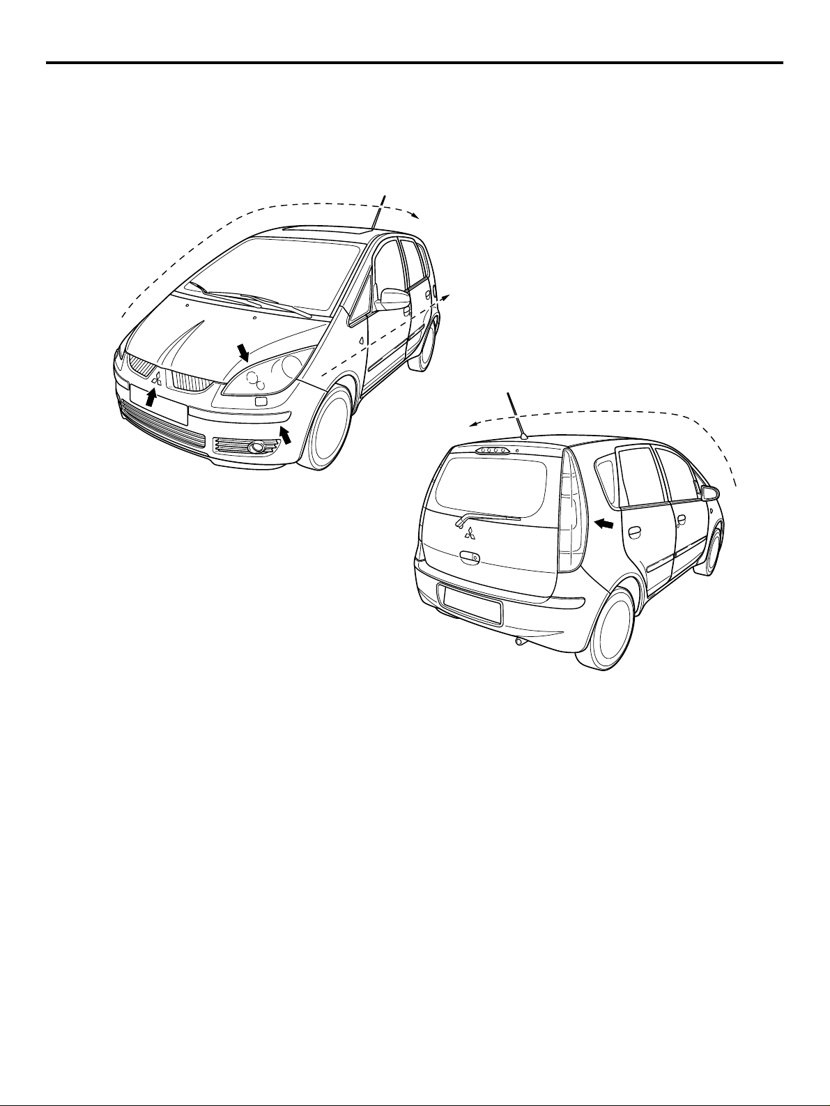
EXTERIOR
DESIGN FEATURES
3
M2000017000331
1
5
2
1
4
OVERALL
• Dynamic one motion line connects chamfered
front end.
• Simple body side section emphasis the wheel
arches.
• Dynamic DLO (day light opening) creates car is
motion even when car is stop.
• Front lights on the chamfered surface follows one
of the Mitsubishi identity.
• Inside of the light reflectors given high-tech
image of Japanese product.
• Simple exterior design emprises car’s functionality.
• Door cut’s matching the lines of the DLO and rear
light.
6
AC311182
AC
1. SIDE SILHOUETTE
Simple and dynamic one motion curve from the front
nose to the roof end.
2. BODY SIDE SURFACE
Take si mple and cl ean s urface to e mphasi ze wh eel
arches.
3. MITSUBISHI MARK
New Mitsubishi front face which designed every elements connects from three diamonds.
4. FRONT END CORNER
Apply the chamfer shape for easy handling.
5. HEAD LAMP
Create the high-tech image of Japanese product.
Page 4
00-4
GENERAL
TECHNICAL FEATURES
6. TAIL LAMP
Apply long vertical type to easy to recognize from
outside.
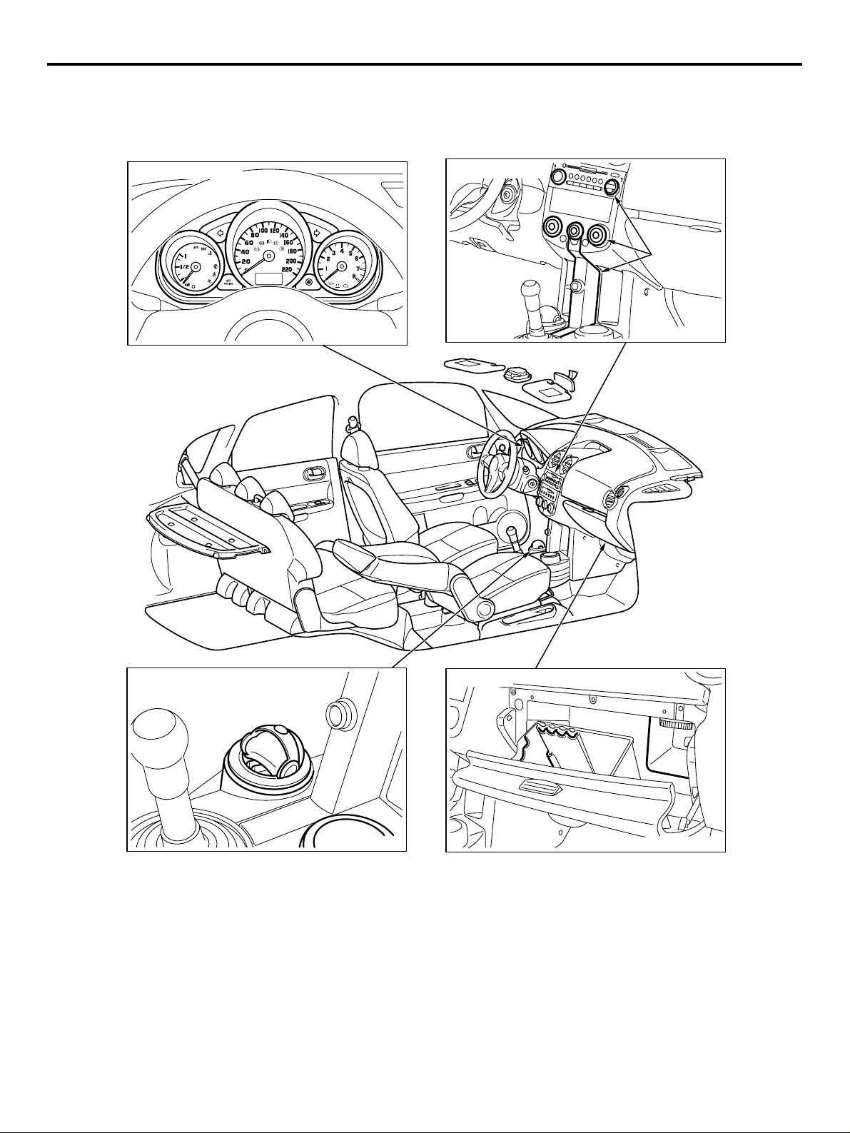
Combination meter
INTERIOR
M2000018000312
DESIGN FEATURES
Instrument panel
Translucent
parts
Cup holder and ashtray
OVERALL
• Sporty elegance feeling with comfortable space.
• The maximum roominess in the limited package.
Glove box
FLOOR CONSOLE AND DOOR TRIM
• Multi cup holder.
• Removable ashtray (This ashtray can be set in all
cup holders).
INSTRUMENT PANEL
• Illumination systems presented by translucent
parts of audio and A/C control panel
• Searchlight system from translucent parts.
• Useful glove box (card holder, pen holder, coin
holders and bottle holder).
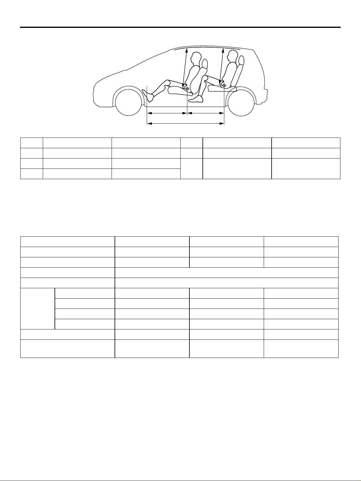
By the adoption of the long wheelbase, it realizes the interior length of the top-class.
COMBINATION METER
• Easy to recognize, independent function meters.
SPACIOUS CABIN
AC312521
AB
M2000000400025
Page 5
GENERAL
TECHNICAL FEATURES
00-5
4
1
3
5
2
AC311954
No. Item Dimension mm No. Item Dimension mm
1 Brake pedal room880 4Front head room 931
2 Hip point couple 825 5Rear head room 862
3Total leg room 1,705
NOTE: Refer to P.00-23 for the body dimensions.
ENGINE
M2000020000223
The following three types of newly developed
engines have been adopted to realize light weight,
small size, and good fuel efficiency. Those engines
are complied with Step 4 in European emissions regulations.
AB
Item 134910 135930 135950
Total displa cemen t mL 1,124 1,332 1,499
Bore × stroke mm 75 × 84.8 75 × 75.4 75 × 84.8
Compression ratio 10.5
Combustion chamber Pentroof-type
Valve
timing
Intake opening BTDC 41° − ATDC 9° BTDC 41° − ATDC 9° BTDC 41° − ATDC 9°
Intake closing ABDC 19° − ABDC 69° ABDC 3° − ABDC 53° ABDC 11° − ABDC 61°
Exhaust opening BBDC 35° BBDC 35° BBDC 39°
Exhaust closing ATDC 5° ATDC 5° ATDC 5°
Maximum output kW(PS)/rpm 55(75)/6,000 70(95)/6,000 80(109)/6,000
Maximum torque
100(10.2)/3,500 125(12.7)/4,000 145(14.8)/4,000
N⋅m(kg-m)/rpm
TRANSMISSION
M2000021000226
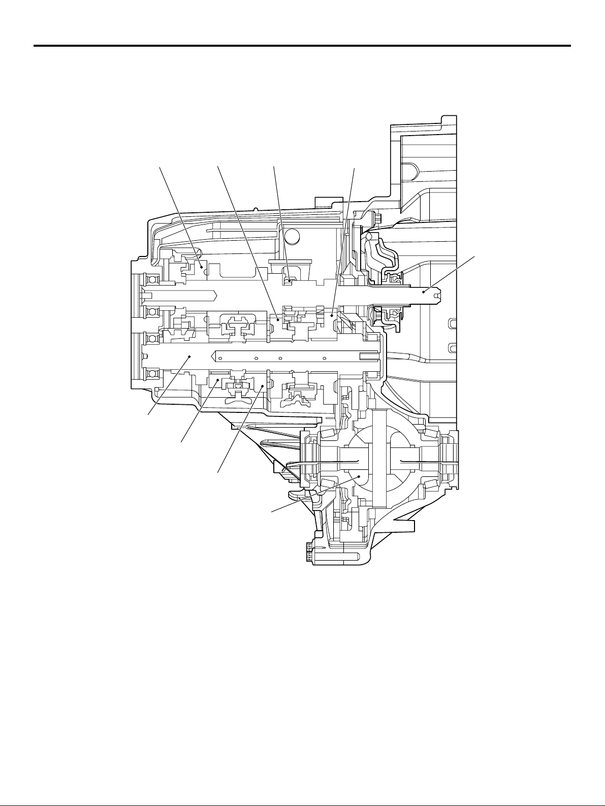
• F5MGA 5-speed manual transmission
• F6SGA 6-speed automated manual transmission
The following two types of newly developed transmissions with light weight and small-size design
have been adopted to realize good fuel efficiency.
Page 6
00-6
MANUAL TRANSMISSION
SECTIONAL VIEW
GENERAL
TECHNICAL FEATURES
5th gear
Output shaft
4th gear
2nd gear
Reverse gear
1st gear
Input shaft
3rd gear
Differential
AC311790
AC
Page 7
GENERAL
TECHNICAL FEATURES
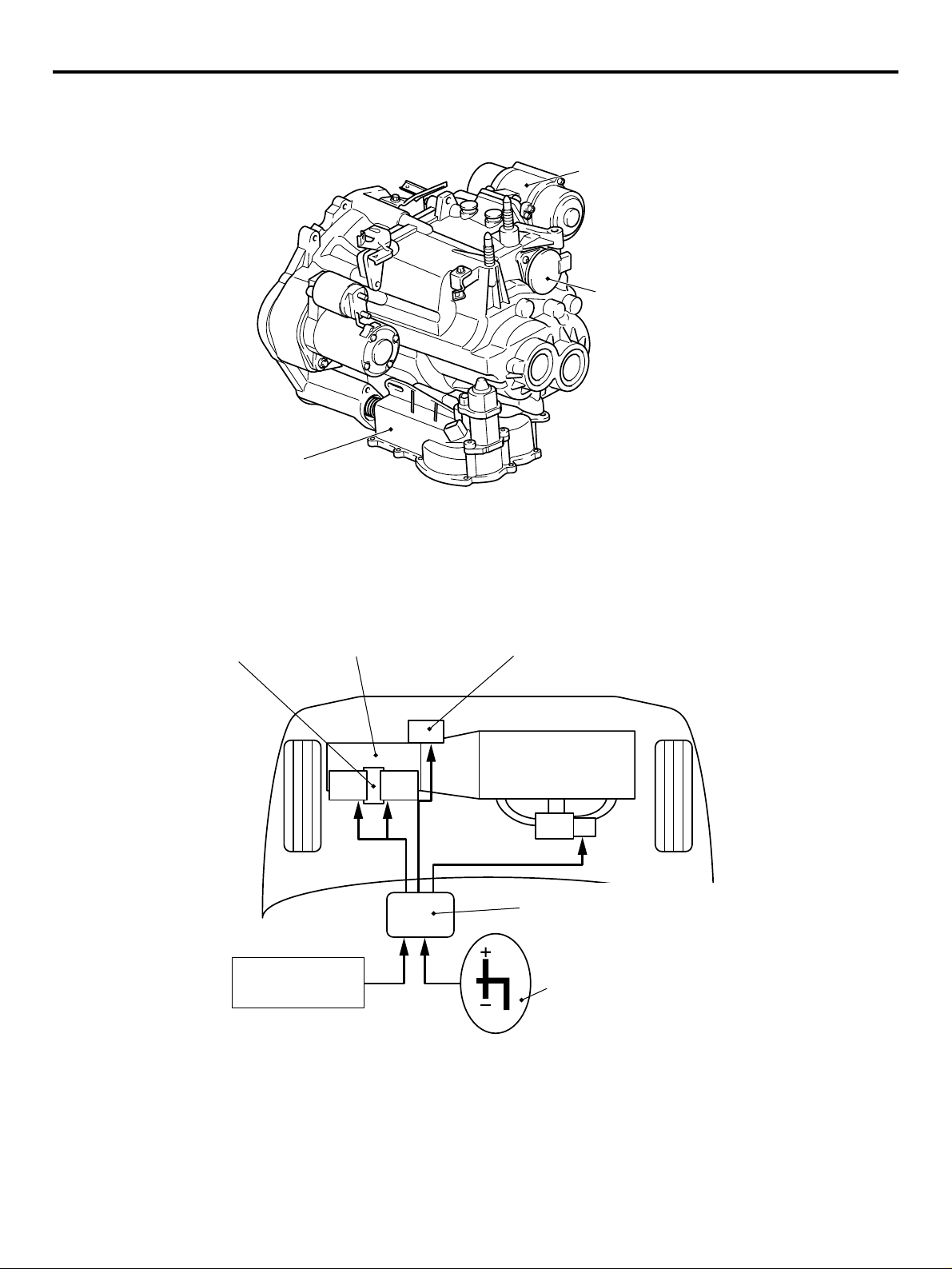
AUTOMATED MANUAL TRANSMISSION
OUTSIDE VIEW
Clutch actuator
Shift actuator assembly
Drum position sensor
AC311791
00-7
AB
As automated manual transmission is designed
based on 6-speed manual gearbox and driven by
electric actuators (motors) via sophisticated
twin-drum shift mechanism, it gives our customers
"easy to drive as A/T", "fun to drive and high fuel efficiency as M/T".
Shift actuator
assembly
Automated manual transmission
Accelerator pedal
Brake pedal
SCHEMATIC DIAGRAM
Clutch actuator
Engine
Engine automated manual
transmission electronic control unit
(Engine-A-M/T-ECU)
A
N
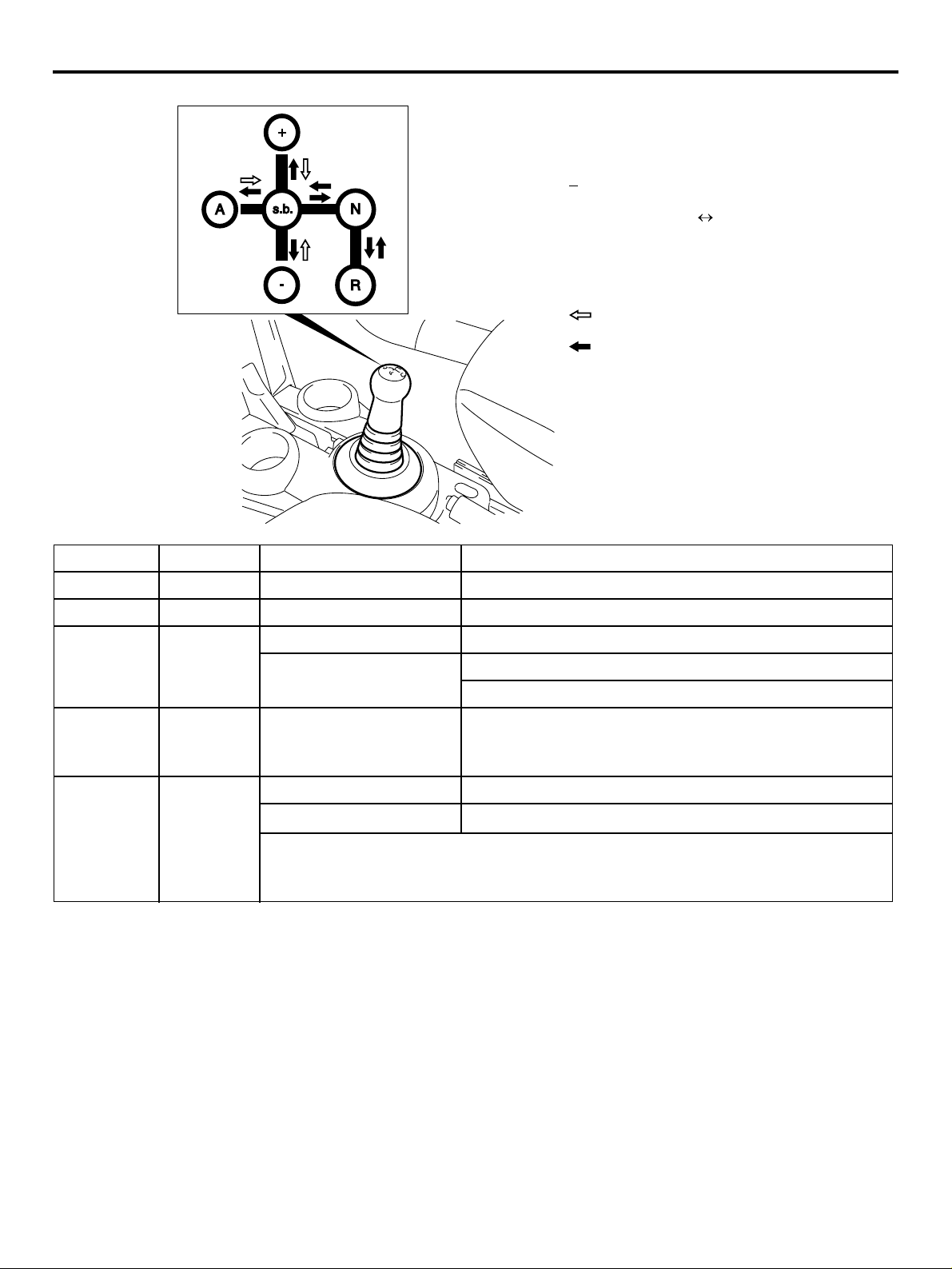
Allshift lever
R
AC311704
AB
DRIVING MODE
Driving mode provides either manual mode (like
sequential M/T) or automatic mode (like conventional
A/T), by tipping shift lever toward "A" or "+" or "−"
from "s.b." position.
Page 8
00-8
GENERAL
TECHNICAL FEATURES
+: Up shifting
s.b.: Stand by (manual selection of gear)
: Down shifting
A: Switch automatic manual mode
N: Neutral
R: Reverse gear
: Automatic resume
: Manual operation
Position Operation Function Further explanation
"N" In "N" Neutral Engine start possible only at "N".
"R" "N" → "R" Reverse drive No creeping.
s.b. (stand
by)
"A" s.b. → "A"
"N" → s.b. Forward drive Creeping starts (with brake pedal depress).
Auto mode or Manual
mode
Starts from auto mode. <135950>
Starts from manual mode. <135930>
Mode change Auto mode or Manual mode comes alternatively.
(tip)
(Auto mode → Manual mode → Auto mode → Manual
mode)
"+", "−"s.b. → "+"
(tip)
s.b. → "−"
(tip)
+: Manual up shifting Higher gear will be selected. *1, *2
−: Manual down shifting
Lower gear will be selected. *1, *3
*1: After "+" or "−" tip action, mode becomes manual mode.
*2: If vehicle speed is too low, some up shifts neglected.
*3: If engine speed is too high, down shifting neglected.
SUSPENSION
M2000023000211
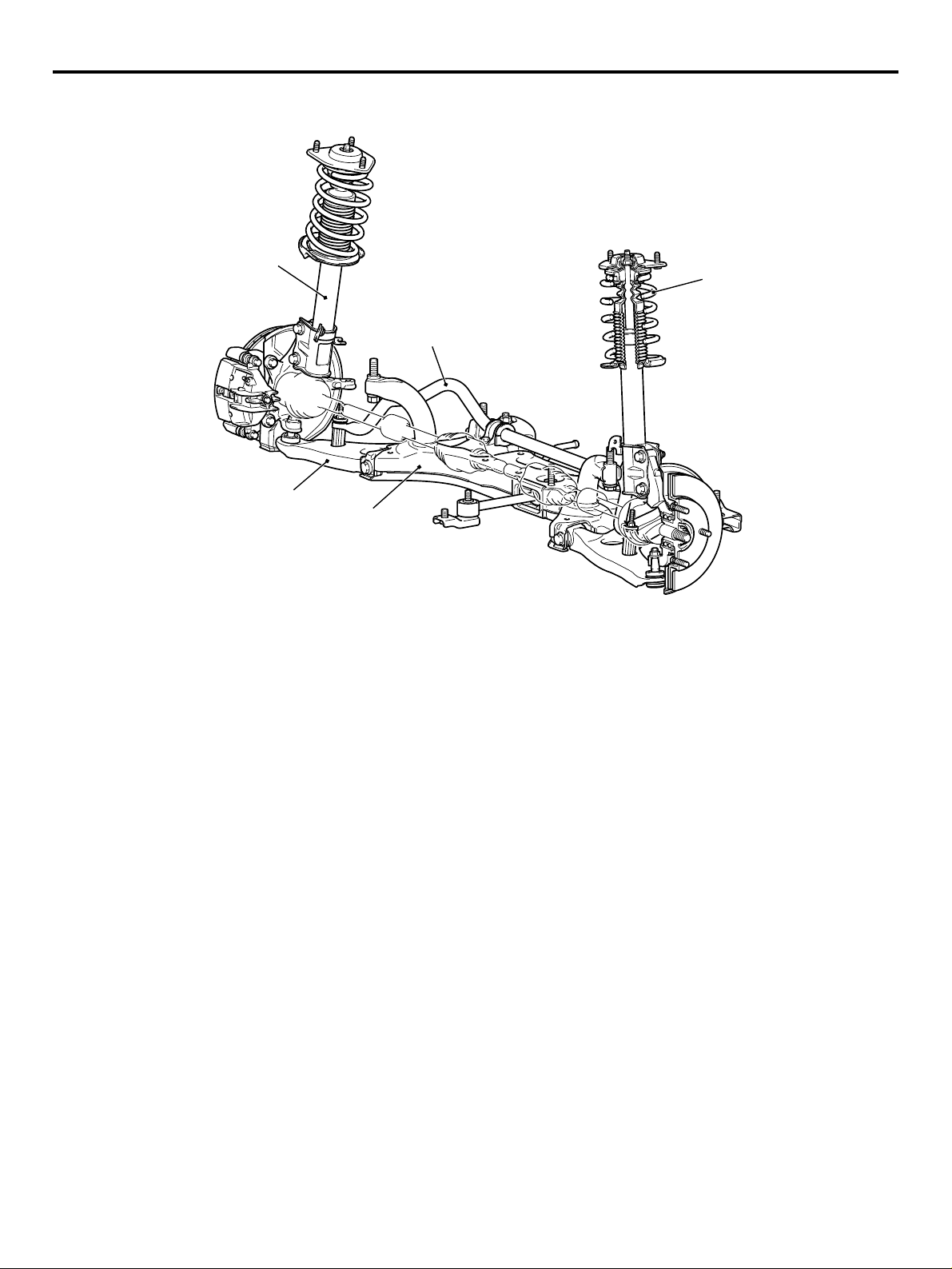
FRONT SUSPENSION
The newly developed MacPherson Strut suspension
with compatible characteristics of high rigidity and
light weight has been adopted for the front suspension to realize sufficient driving comfort and driving
stability.
AC312516
AB
Page 9
GENERAL
TECHNICAL FEATURES
00-9
Strut assembly
Stabilizer bar
Lower arm
Crossmember
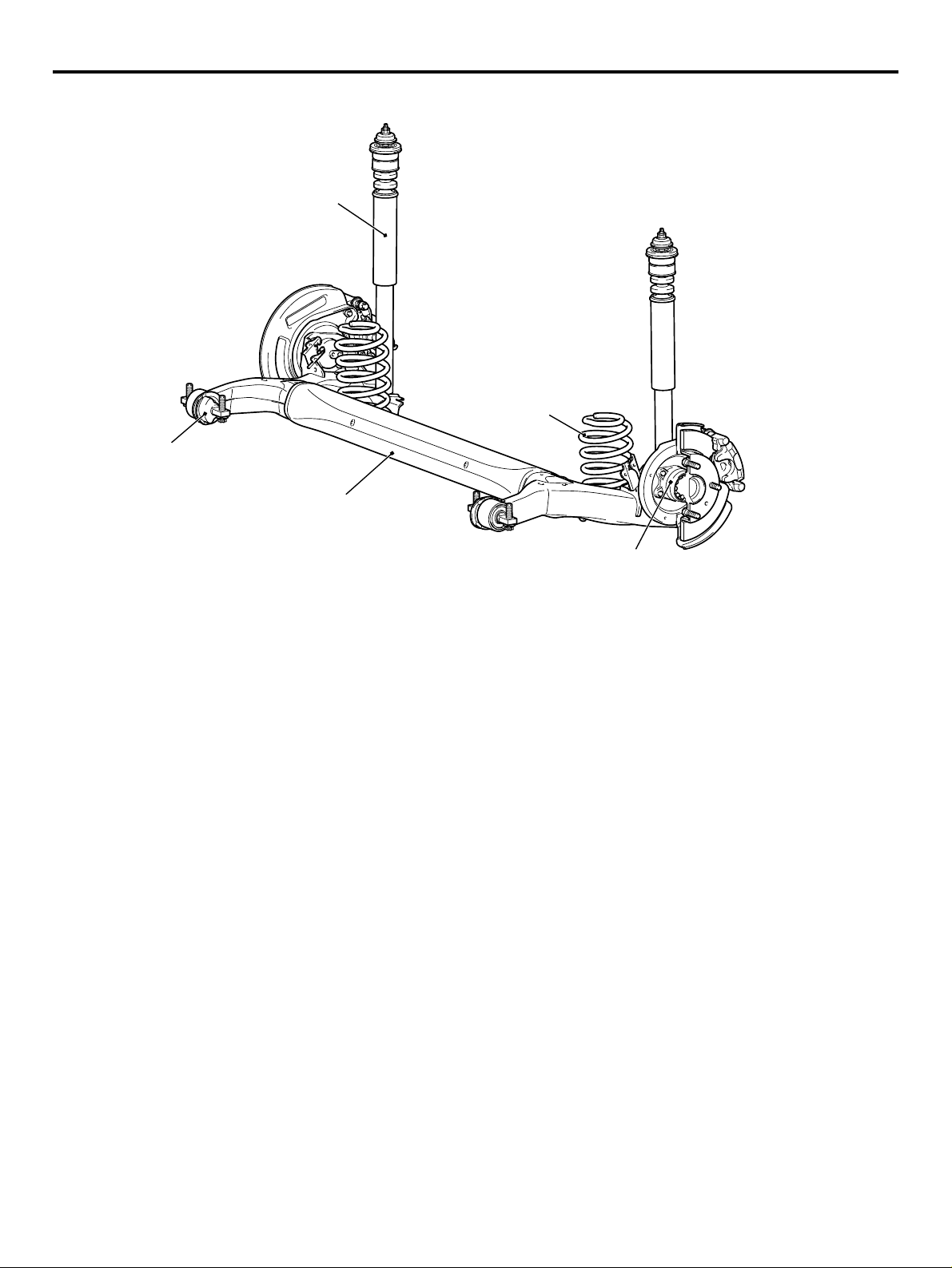
REAR SUSPENSION
The torsion beam suspension has been adopted for
the rear suspension to realize a large suspension
stroke and excellent driving comfort. The suspension
with small-size design has provided ample interior
space.
Coil spring
AC310151
AB
Page 10
00-10
GENERAL
TECHNICAL FEATURES
Shock absorber
Coil spring
Arm bushing
Torsion beam and arm assembly
BRAKE
M2000024000043
14-inch ventilated disk brake for the front, 8-inch
leading trailing drum brake or 14-inch solid disk
brake for the rear have been installed to realize high
reliability and durability along with excellent braking
performance.
Unit type bearing
AC310152
AB
Page 11
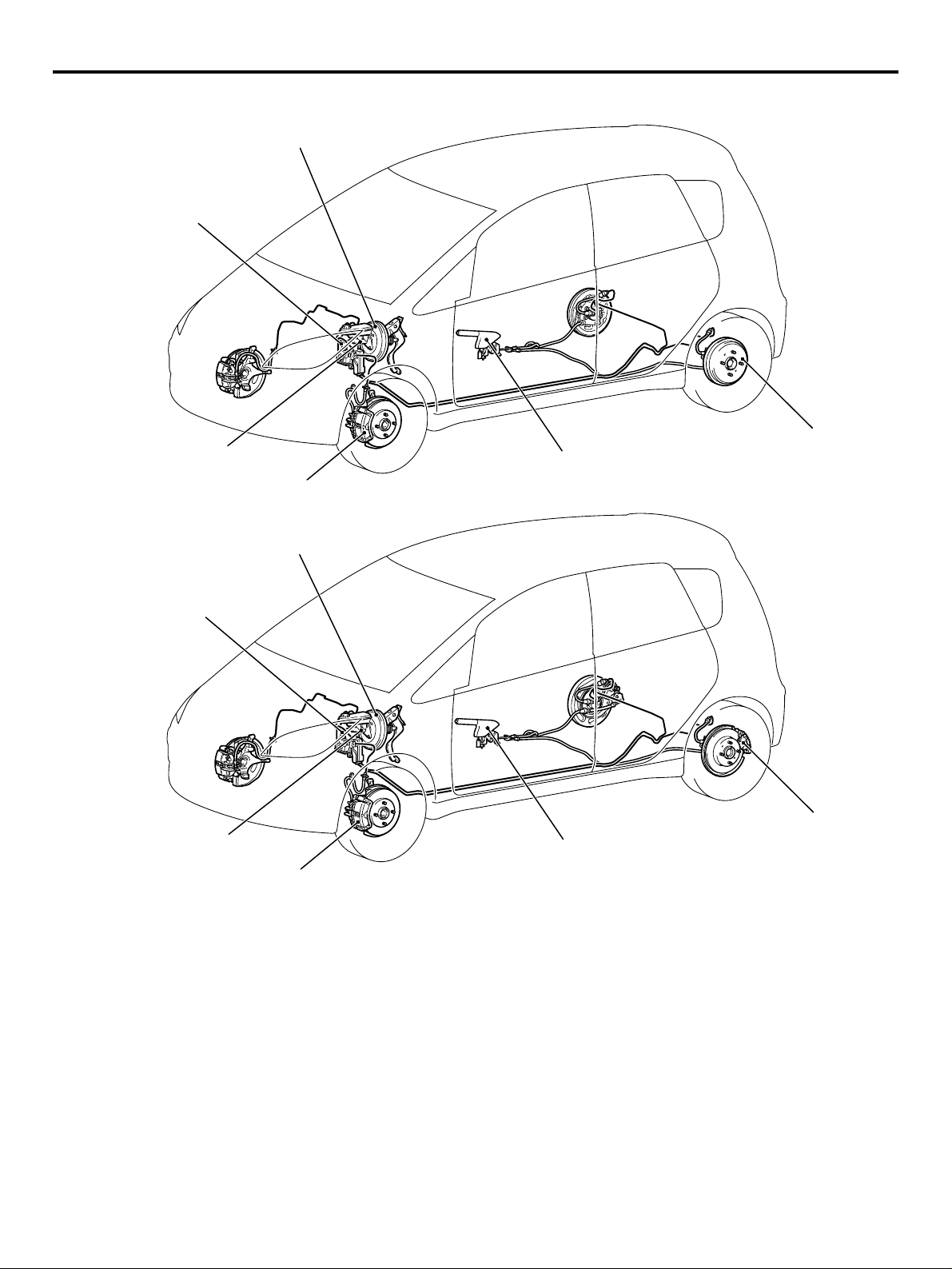
<Vehicle with rear drum brake>
Brake booster
Hydraulic unit
(Integrated with ABS-ECU/Active
Stability Control System-ECU)
GENERAL
TECHNICAL FEATURES
00-11
Master cylinder
Front disc brake
<Vehicle with rear disc brake>
Brake booster
Hydraulic unit
(Integrated with ABS-ECU/Active
Stability Control System-ECU)
Master cylinder
Front disc brake
Parking brake lever
Parking brake lever
Rear drum brake
AC311564
Rear disc brake
AC311651
AC311650
AB
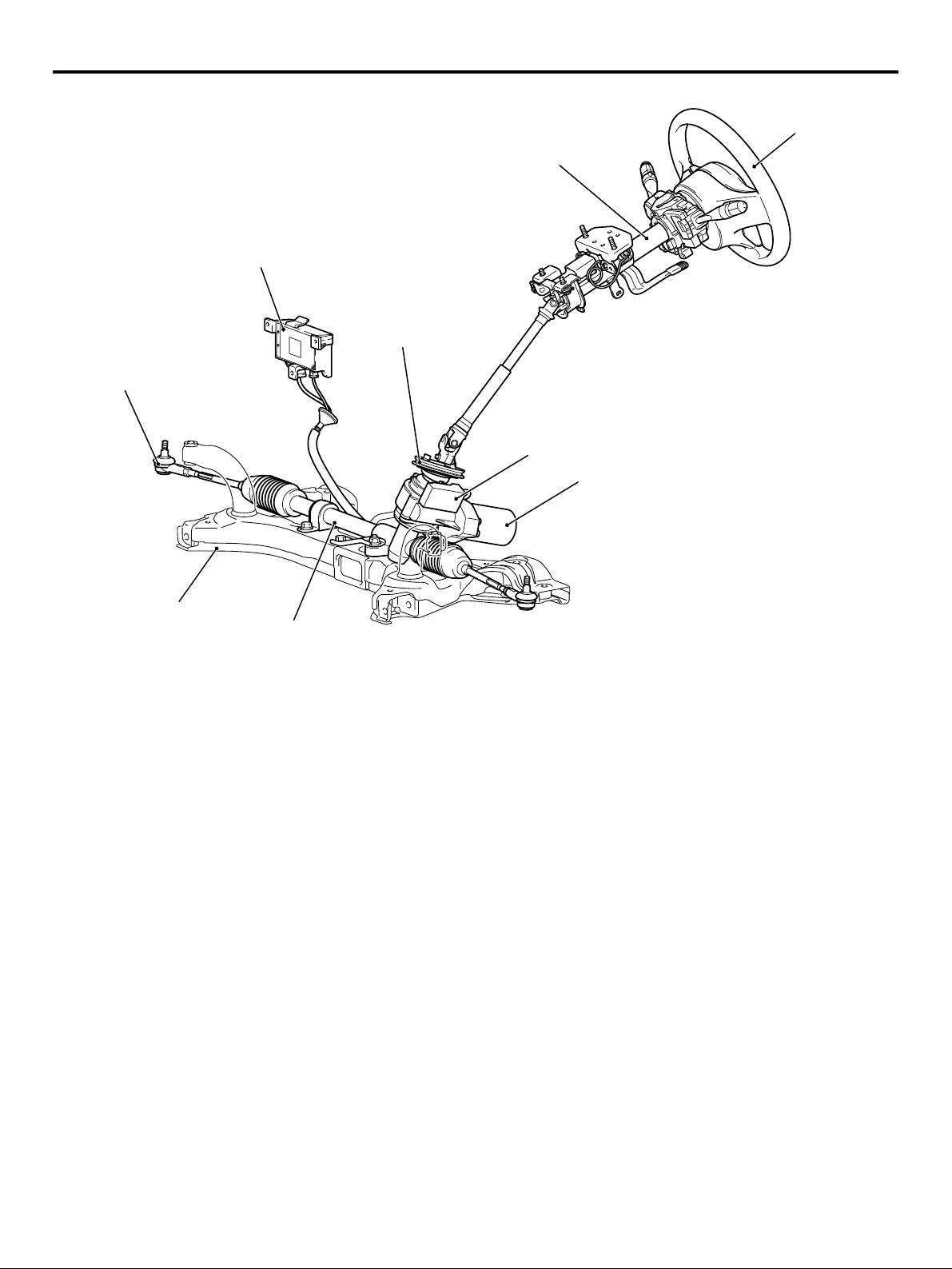
STEERING
M2000040000010
Due to the adoption of electric power steering driven
by newly developed pinion shaft, effortless steering
wheel manoeuvring at the low speed as well as stable steering wheel manoeuvring at the mid to high
speed has been achieved.
Page 12
00-12
Tie rod end
GENERAL
TECHNICAL FEATURES
Steering wheel
Steering column assembly
Electric power steering-ECU
Dash panel cover
Torque sensor
Motor
Crossmember
Steering gear
LOCAL INTERCONNECT NETWORK (LIN)
M2000041000013
LIN refers to "Local Interconnect Network", a global
standard of serial multiplex communication protocol
administrated by LIN consortium. A communication
circuit employing the LIN protocol connects each
ECU, and switch data can be shared among ECUs,
which enables more reduction in wiring. Transmission speed is 19.2 kbps.
*2
For COLT, ETACS
signals through CAN*
-ECU can receive some input
3
communication in addition to
the LIN communication.
*1
AC310150
NOTE:
*1
: The regulations have been decided in
detail, from software matters such as the necessary
transmission rate for communication, the system,
data format, and communication timing control
method to hardware matters such as the harness
type and length and the resistance values.
NOTE: *
2
: ETACS (Electronic Time and Alarm Con-
trol System)
NOTE: *
3
: CAN (Controller Area Network)
AB
Page 13
GENERAL
TECHNICAL FEATURES
00-13
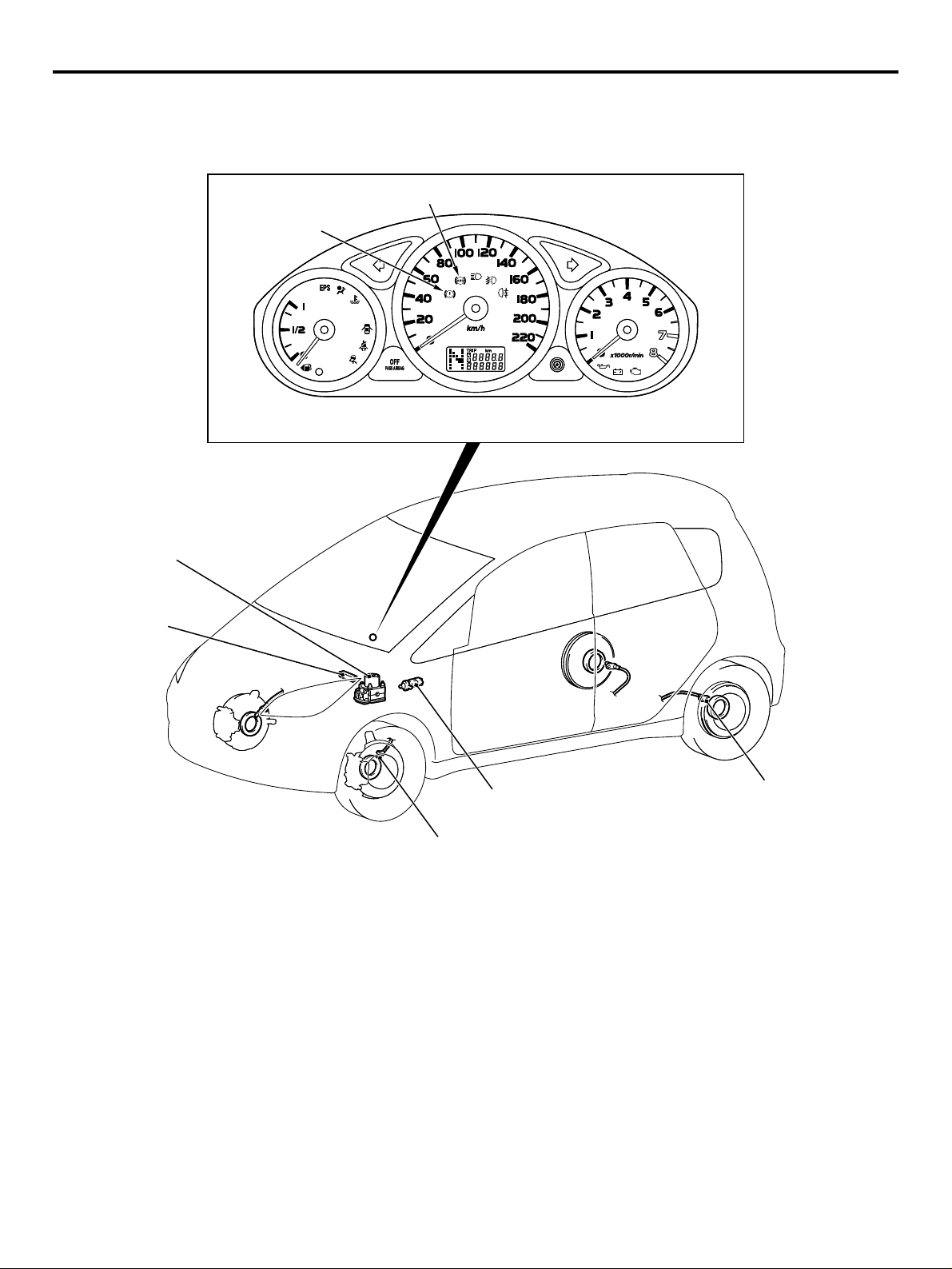
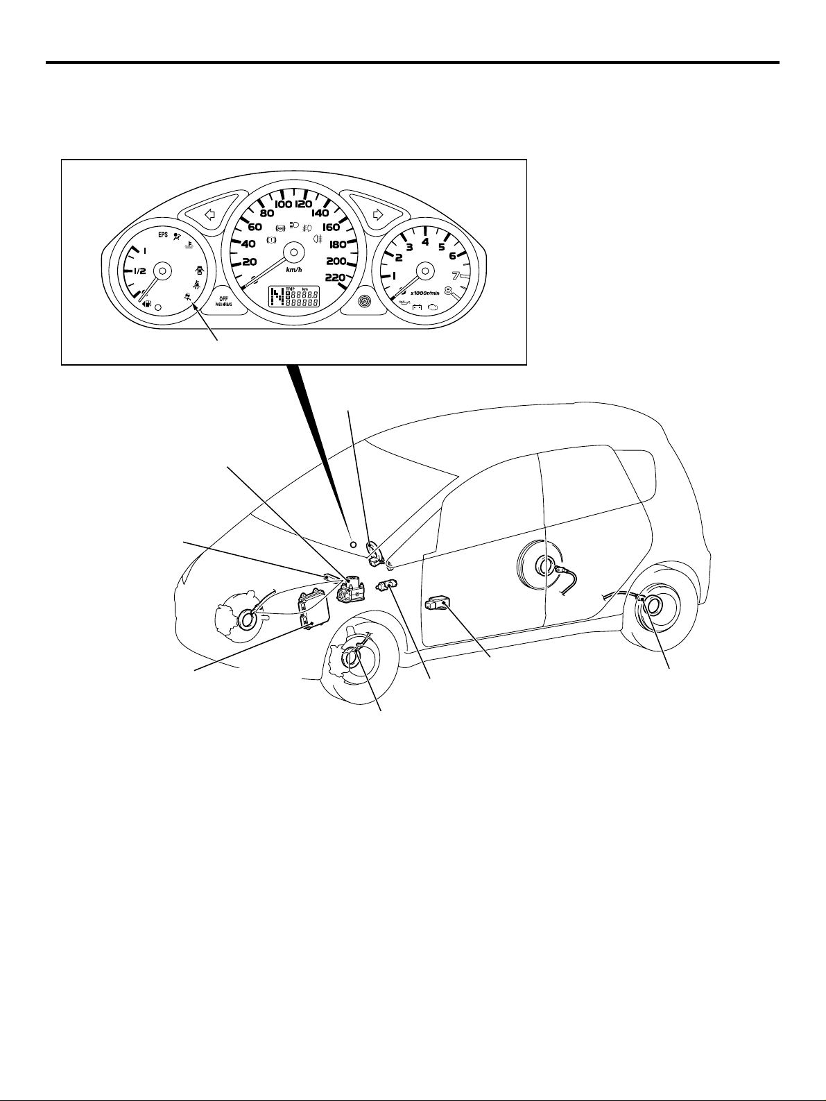
ACTIVE SAFETY
BRAKING SYSTEM
Brake warning lamp
Hydraulic unit and
ABS-ECU
M2000031000216
ABS warning lamp
AC311642
AC311642
Diagnosis
connector
Wheel speed sensor
Stop lamp switch
Wheel speed sensor
AC311643
AC311643
AC311644
AC311644
AC
Page 14
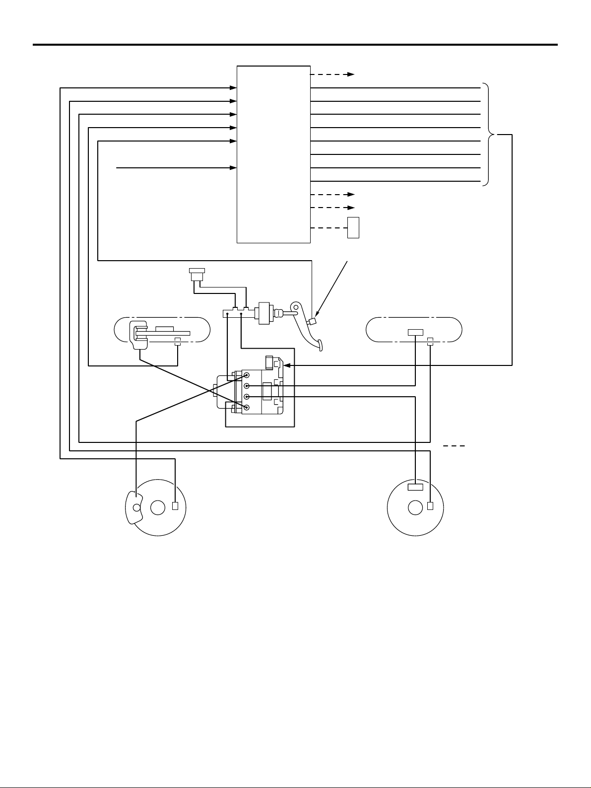
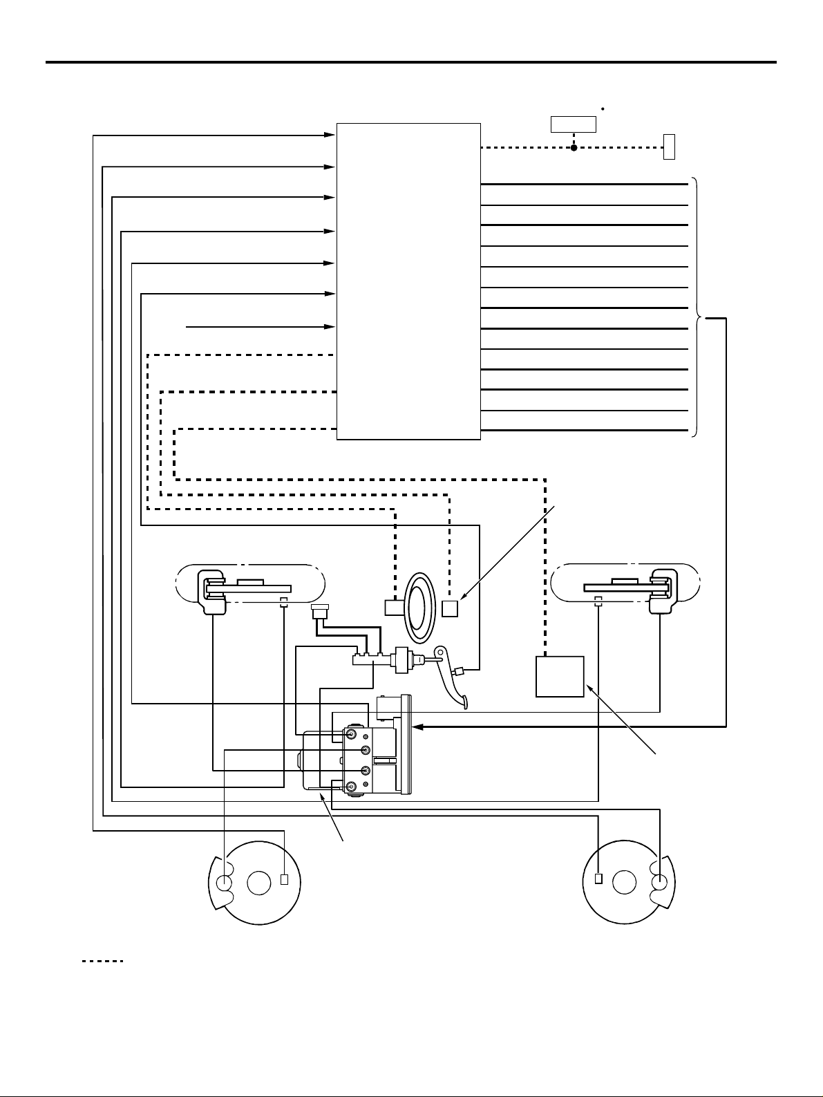
00-14
Front-left wheel speed sensor
Rear-left wheel speed sensor
Rear-right wheel speed sensor
Front-right wheel speed sensor
Stop lamp switch
ABS-ECU power supply
GENERAL
TECHNICAL FEATURES
Front right solenoid valve (out)
Front right solenoid valve (in)
Front left solenoid valve (out)
Front left solenoid valve (in)
Rear right solenoid valve (out)
ABS-ECU
Rear right solenoid valve (in)
Rear left solenoid valve (out)
Rear left solenoid valve (in)
ABS warning lamp
Stop lamp switch
Engine-ECU <M/T> or Engine-A-M/T-ECU*
<Automated manual transmission>
Brake warning lamp
Diagnosis connector
Front-right wheel (FR)
Front-right
wheel
speed
sensor
Hydraulic
unit (HU)
Front-left wheel
speed sensor
Front-left wheel (FL)
4-WHEEL ANTI-SKID BRAKING SYSTEM
(4ABS)
A 4-wheel anti-skid braking system (4ABS) has been
adopted to prevent slipping caused by the vehicle
wheels locking up, in order to minimize braking distance, and also to maintain a stable vehicle posture
and steering performance.
Rear-right wheel (RR)
Rear-right wheel
speed sensor
Note
*Engine-A-M/T-ECU:
Engine automated manual
transmission electronic
control unit
: CAN-bus line
Rear-left wheel
speed sensor
Rear-left wheel (RL)
AC311645
AC
ELECTRONIC BRAKE-FORCE
DISTRIBUTION (EBD)
An electronic brake-force distribution (EBD) which
makes it possible to maintain the maximum amount
of braking force even when the vehicle's load is varied has been adopted.
Page 15
TECHNICAL FEATURES
ANTI-SKID BRAKE SYSTEM
(ABS)/ACTIVE STABILITY CONTROL
SYSTEM
Anti-skid Brake/Active stability control indicator lamp
Steering wheel
sensor
Pressure sensor, Hydraulic unit and
Anti-skid Brake/Active stability
control system control unit
(ABS/Active stability control
system-ECU)
GENERAL
00-15
Diagnosis
connector
Engine-ECU <M/T> or Engine-A-M/T-ECU
(Engine automated manual transmission
electronic control unit)
<Automated manual transmission>
Stop lamp switch
Wheel speed sensor
G and yaw rate sensor
Wheel speed sensor
AC311649
AC
Page 16
00-16
Front-left wheel speed sensor
Rear-left wheel speed sensor
Rear-right wheel speed sensor
Front-right wheel speed sensor
Master cylinder pressure sensor
Stop lamp switch
Power supply to ABS/Active stability
control system-ECU
Steering wheel sensor
G and yaw rate sensor
Engine-ECU <M/T> or engine-AM/T-ECU <Automated manual
transmission>
GENERAL
TECHNICAL FEATURES
Suction valve (FR)
Suction valve (FL)
Cut valve (FR)
Cut valve (FL)
Control solenoid valve (FR) IN
ABS/Active stability
control system-ECU
Control solenoid valve (FR) OUT
Control solenoid valve (FL) IN
Control solenoid valve (FL) OUT
Control solenoid valve (RR) IN
Control solenoid valve (RR) OUT
Control solenoid valve (RL) IN
Control solenoid valve (RL) OUT
Pamp motor
Combination meter
ABS/Active stability control
indicator lamp
Diagnosis
Connector
Front-right wheel (FR)
Wheel
speed
sensor
Steering
wheel
sensor
Hydraulic
unit
Wheel speed
sensor
G and yaw rate sensor
Rear-right wheel (RR)
Wheel
speed
sensor
Stop lamp
switch
Engine-ECU <M/T> or engineA-M/T-ECU <Automated manual
transmission>
Wheel speed
sensor
Note
: CAN-bus line
Front-left wheel (FL)
Rear-left wheel (RL)
AC311782
AC
Page 17
GENERAL
TECHNICAL FEATURES
00-17
The Anti-skid Brake System (ABS)/Active stability
control system is a combination system of active stability control system and anti-skid brake control system. The active stability control system avoids a
dangerous vehicle attitude by limiting the engine output and braking a set of wheels (left front and right
rear, or right front and left rear) according to driving
conditions. The anti-skid brake control system prevents wheel spinning at vehicle start.
ABS/Active stability control system is available for all
models as optional equipment.
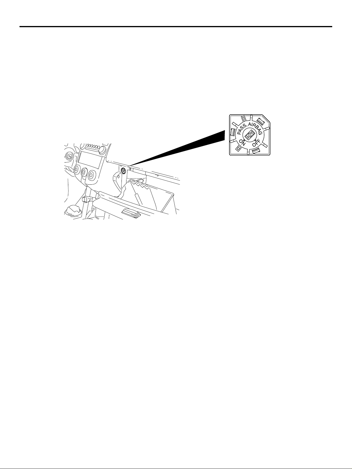
PASSENGER’S AIR BAG CUT OFF
SWITCH
AC311721
AC311720
Passenger’s air bag cut off switch is located in the
glove box.
The passenger’s air bag cut off switch can be used to
disable the passenger's (front) air bag.
AC312760
AB
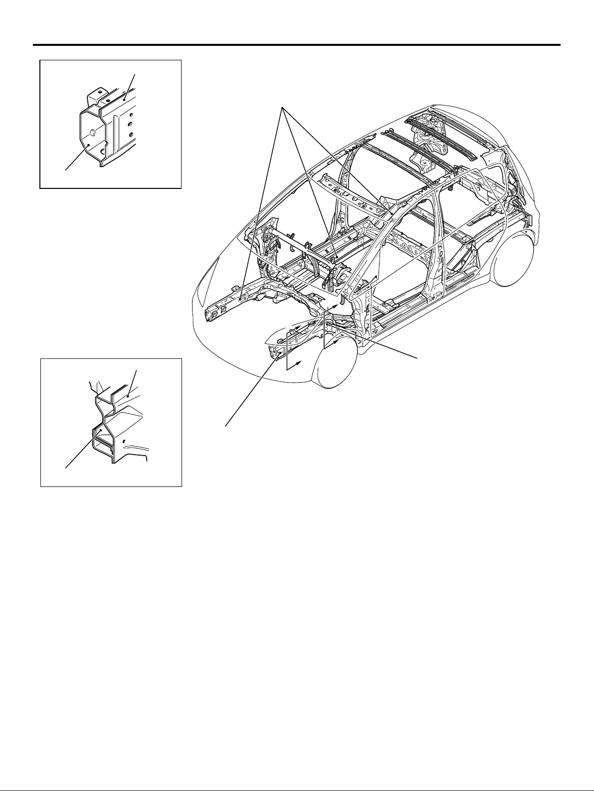
PASSIVE SAFE TY
M2000032000208
IMPACT SAFETY BODY
The front and rear structures to absorb high energy,
and the highly tough cabin structure reduce the risk
of passenger injuries at front-, rear-, and side-impact
collisions, secure the space for life protection, and
facilitate rescuing passengers.
Page 18
00-18
GENERAL
TECHNICAL FEATURES
Section A - A
Front side member
inner
Section B - B
Front side member
outer
AB301790
Front side member
outer
2
B
A
B
AB301783
1
A
1
Front side member
inner
1. The octagonal cross section for the front of the
front sidemember and 8-shaped cross section for
the rear of the front sidemember have been
adopted for enlargement so that the applied
structures can effectively absorb energy from the
impact at the time of collision.
AB301791
AB301835
2. Due to the adoption of straightened front sidemember and the rear floor sidemember, the
structure can effectively absorb energy from the
impact at the time of collision.
AB
Page 19
TECHNICAL FEATURES
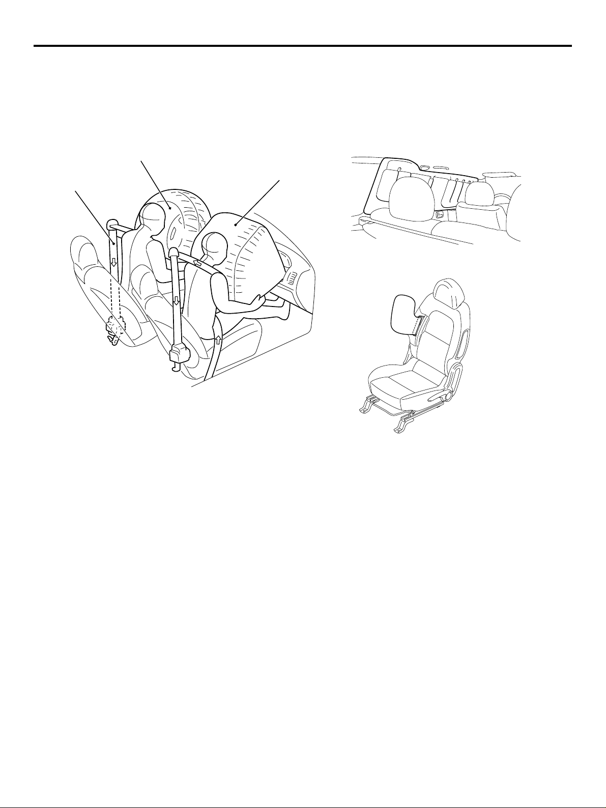
SUPPLEMENTAL RESTRAINT SYSTEM
(SRS) AND FRONT SEAT BELTS WITH
PRE-TENSIONER
GENERAL
00-19
Seat belt with
pre-tensioner
Driver's air bag
module
Curtain air bag modules
Passenger's (front)
air bag module
Side air bag modules
SUPPLEMENTAL RESTRAINT SYSTEM
(SRS)
The SRS is designed to supplement the front seat
belts. It eliminates or reduces injury to the front passenger(s) by deploying air bag(s) in case of a
head-on collision.
SRS SIDE AIR BAG
Side air bag systems in the front seats are activated
when sideward impacts applied to the vehicle exceed
a threshold to protect the occupants’ upper bodies.
SRS CURTAIN AIR BAG
The curtain air bag systems are activated when sideward impacts applied to the vehicle exceed a threshold, to protect the heads of the occupants in the front
and rear seats.
AC313299
AB
SEAT BELT WITH PRE-TENSIONER
The seat belts with pre-tensioner work simultaneously with the SRS. The pre-tensioner takes up seat
belt slack immediately when a collision takes place,
restraining the front passengers sooner than the
SRS. This prevents the passengers from moving forward.
STEERING SHAFT AND STEERING
COLUMN
The impact absorption mechanism in combination of
retractable steering shaft and steering column disengagement mechanism has been adopted to alleviate
the impact from the steering wheel to the driver.
BRAKE PEDAL
The brake pedal backward movement restraint
mechanism to restrain the backward movement of
the brake pedal to the minimum at the time of frontal
collision has been adopted so that the impact to the
lower limbs of the driver can be alleviated.
Page 20
00-20
GENERAL
TECHNICAL FEATURES
CHILD SEAT FIXING BAR COMPATIBLE
WITH ISO FIX*
The anchor bar has been equipped as standard for
easily and securely fixing the child seat compatible
with ISO FIX.
NOTE: *ISO: International Organisation for Standardisation
REAR SEAT BELT WITH CHILD SEAT
FIXING MECHANISM (ALR*)
The child seat fixing mechanism has been adopted
to easily and securely fix the child seat that is not
compatible with ISO FIX.
NOTE: *ALR: Automatic Locking Retractor
POWER WINDOW WITH SAFETY
MECHANISM
The power window with safety mechanism has been
adopted to automatically roll down and stop the door
window glass as soon as the occurrence of jamming
is detected at the time of rolling up the door window
glass.
SUNROOF WITH SAFETY MECHANISM
The sunroof with safety mechanism has been
adopted so that the roof lid glass can move in the
reverse direction and stop when application of external force hinders the movement during the sliding to
close or tilt down operation.
TRIMS AND HEADLINING
The head impact absorption structure has been
adopted for the pillar trim, quarter trim, and headlining so that impact towards the head of a passenger
can be reduced.
OTHER SAFETY FEATURES
• 3-point ELR seat belts
• Child-protection rear door locks
• Front fog lamps <Optional>
• Rear fog lamp (Driver’s side)
EQUIPMENTS
M2000026000191
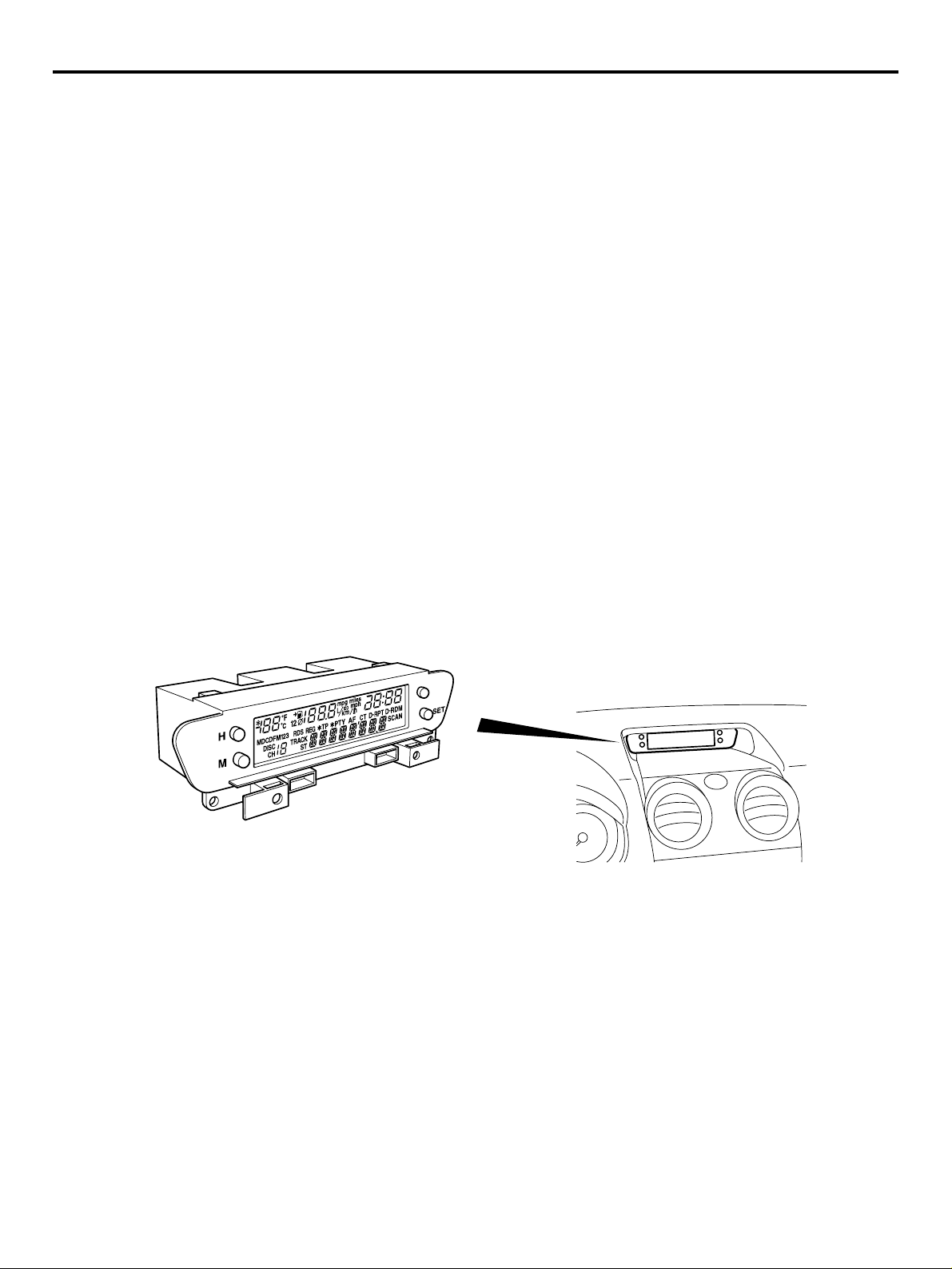
MULTI-CENTRE DISPLAY
Multi-centre display
The multi-centre display to provide vehicle information in the text form has been equipped on the centre
console as standard. The multi-centre display has
the following functions:
• Clock
AC311613
• Outside temperature
• Vehicle information (average speed, instant fuel
consumption, remaining distance)
• Audio information
AB
Page 21
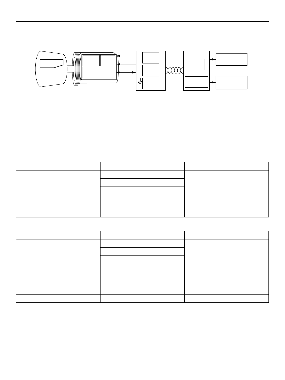
IMMOBILIZER SYSTEM
GENERAL
TECHNICAL FEATURES
00-21
Ignition key Key ring antenna
Encrypted
code
Transponder
Note
*Engine-A-M/T-ECU: Engine automated manual transmission electronic control unit
AMP SCI
RF circuit
Steering lock
All models are equipped with the immobilizer system
as standard. The immobilizer system is the theft prevention system designed for prohibiting the engine
from fuel injection so that the vehicle cannot be
started if someone tries to start the engine with
something other than the ignition key encrypted for
ETACS-ECU
(immobilizer-ECU)
Power
Clock
Data
Engine-ECU <M/T> or Engine-A-M/T-ECU*
<Automated manual transmission>
SCI
CPU
CANI/F
CANBus
CPU
CAN-I/F
Ignition
Injection
AC312166
ENVIRONMENTAL PROTECTION
M2000027000257
Mitsubishi has given careful consideration to protection of natural resources and the environment in the
vehicle. Environmentally friendly features are shown
below.
that vehicle.
IMPROVEMENT ON RECYCLING EFFICIENCY
Category Part name Feature
Recyclable materials Door handle Thermo plastics-easy recyclable
Bumper
AC
Radiator grille
Instrument panel
Recycled materials Engine oil level gauge Recycled from other industries
scrap
REDUCTION OF MATERIAL BURDEN ON ENVIRONMENTt
Category Part name Feature
Elimination of hazardous
substances
Radiator core and heater core Lead free materials
Windshield ceramic print
Body electrodeposited coating
Battery cable connector
Wiring harness
Water proof film Polyvinyl chloride (PVC) free
material
Prevention of ozone depletion Air conditioner refrigerant HFC134a refrigerant
SERVICEABILITY AND RELIABILITY
M2000028000272
MUT-III (MULTI USE TESTER-III)
Comprehensive improvements have been made to
the MUT-II, a tester for diagnosing problems with the
electronic control system. For easier servicing, the
newly developed MUT-III has greatly improved functions and is much easier to use. The MUT-III
expands the functions of the MUT-II in the following
ways:
1. Interactive Error Diagnosis
• In response to the nature of the problem, the
corresponding troubleshooting page from the
maintenance manual is retrieved.
• Service data is displayed, and from the actuator test screen, the page of the maintenance
manual is retrieved for a list of inspection reference values.
Page 22

00-22
GENERAL
VEHICLE IDENTIFICATION
2. Service Manual Viewer
• The technical information manual and workshop manual can be displayed on a personal
computer monitor.
3. CAN* bus diagnosis
• Auto diagnosis function for the CAN communications bus line.
NOTE: *CAN: Controller Area Network (for further
details, refer to GROUP 54C P.54C-2).
IMPROVED SERVICEABILITY
• Since adoption of unvolatile memory (EEPROM*)
helps the learned value not to be initialised when
the battery terminal or connector of the control
unit is disconnected, maintainability can be
improved.
VEHICLE IDENTIFICATION
MODELS
NOTE: *EEPROM: Electrical Erasable Programma-
ble ROM (information to be memorised can be
electronically written into and erased from ROM)
• Since the adoption of service hole at the quarter
trim is designed for removal and installation of the
rear shock absorber assembly, maintainability
can be improved.
• Since the adoption of electric power steering
makes hydraulic pipes and oil pumps unnecessary, maintainability can be improved.
• Since adoption of service hole at the splash
shield helps for removal and installation of headlamp bulb (low beam) and front turn signal lamp
bulb, maintainability can be improved.
• The instrument lower panel can be removed or
installed without using tools at the time of fuse
replacement in the junction block.
M2000001000644
Model code Engine model Transmission model Fuel supply
system
Z32A XNLHL6 134910-DOHC MIVEC (1,124 mL) F5MGA <2WD, 5M/T> MPI
XNLHR6
Z34A XNLHL6 135930-DOHC MIVEC (1,332 mL)
XNLHR6
XJLHL6 F6SGA <2WD, 6-speed
XJLHR6
Z36A XNLHL6 135950-DOHC MIVEC (1,499 mL) F5MGA <2WD, 5M/T>
XNLHR6
XJLHL6 F6SGA <2WD, 6-speed
XJLHR6
MODEL CODE
2
Z3
1
2
A
N
X
4
3
5
H
L
L
6
7
6
8
9
No. Item Content
1DevelopmentZ3MITSUBISHI COLT
2Engine type 21,124 mL petrol engine
3Sort APassenger car
4Body style X4-door hatchback
automated manual
transmission>
automated manual
transmission>
41,332 mL petrol engine
61,499 mL petrol engine
AC311514
Page 23
No. Item Content
GENERAL
MAJOR SPECIFICATIONS
00-23
5Transmission
type
N5-speed manual
transmission
J6-speed automated
manual transmission
6Trim level LL-line
7Specification
HMPI-DOHC MIVEC
engine feature
8Steering wheel
location
LLeft hand drive
RRight hand drive
9Destination 6For Europe
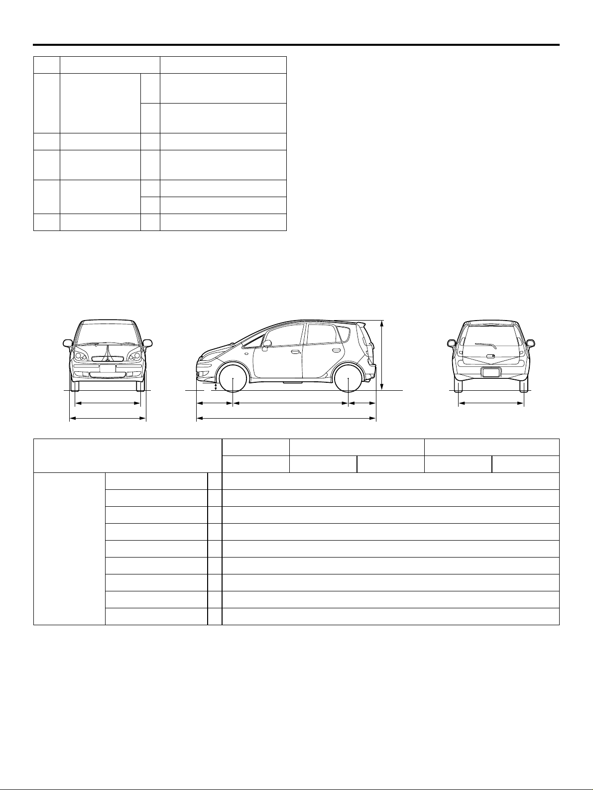
MAJOR SPECIFICATIONS
M2000030000268
8
7
1
2
3
4
6
5
Item Z32A Z34A Z36A
XNLHL6/R6 XNLHL6/R6 XJLHL6/R6 XNLHL6/R6 XJLHL6/R6
Vehicle
dimensions
mm
Front track 1 1,460
Overall width 2 1,695
Front overhang 3 780
Wheel base 4 2,500
Rear overhang 5 590
Overall length 6 3,870
Ground clearance 7 154/169*
Overall height 8 1,550/1,565*
Rear track 9 1,445
9
AC313517
AB
Page 24

00-24
Item Z32A Z34A Z36A
Vehicle
weight kg
Kerb weight 965 970 975 990 995
Max. gross vehicle
weight
MAJOR SPECIFICATIONS
XNLHL6/R6 XNLHL6/R6 XJLHL6/R6 XNLHL6/R6 XJLHL6/R6
1,450 1,460 1,465
GENERAL
Max. axle weight
rating-front
Max. axle weight
rating-rear
Max.
trailer
weight
Max. trailer-nose
weight
Seating capacity 5
Engine Model code 134910 135930 135950
To tal d i splacement mL 1 , 124 1 , 332 1 ,499
Transmission Model code F5MGA F6SGA F5MGA F6SGA
Type 5-speed manual
Fuel system Fuel supply system MPI
NOTE: *: Vehicles with high ground suspension
With brake 1,000
Without
brake
735 745 750
745
500
50
transmission
6-speed
automated
manual
transmission
5-speed
manual
transmission
6-speed
automated
manual
transmission
Page 25

GROUP 11
CONTENTS
ENGINE MECHANICAL <134>. . . . . . . . . . . . . . . . . . . . . . . . . . 11A
ENGINE MECHANICAL <135>. . . . . . . . . . . . . . . . . . . . . . . . . . 11B
11-1
Page 26

11A-1
GROUP 11A
ENGINE
MECHANICAL <134>
CONTENTS
GENERAL INFORMATION . . . . . . . . 11A-2 BASE ENGINE . . . . . . . . . . . . . . . . . . 11A-3
Page 27

11A-2
ENGINE MECHANICAL <134>
GENERAL INFORMATION
GENERAL INFORMATION
The newly developed 1.1L 134910 engine features
3-cylinder, 12-valve, and double overhead camshafts
(DOHC).
The engine family has the following features.
• Aluminum cylinder block
• A counter balance shaft
MAJOR SPECIFICATIONS
Item Specification
Total displa cement mL 1 ,1 24
Bore × Stroke mm 75 × 84.8
Compression ratio 10.5
Compression chamber Pentroof-type
Valve timing Intake openi ng BT DC 41 ° − ATDC 9°
Intake closing ABDC 19° − ABDC 69°
Exhaust opening BBDC 35°
• MIVEC (Mitsubishi Innovative Valve timing Electronic Control system)
• Selective valve tappet of direct acting valve system for valve clearance adjustment
• Timing chain
M2112000100404
Exhaust closing ATDC 5°
Maximum output kW (PS)/rpm 55 (75)/6,000
Maximum torque Nm (kgm)rpm 100 (10.2)/3,500
Fuel system Electronically controlled multipoint fuel injection
Ignition system Electronic-controlled 3-coil
Page 28
CYLINDER HEAD
ENGINE MECHANICAL <134>
BASE ENGINE
BASE ENGINE
11A-3
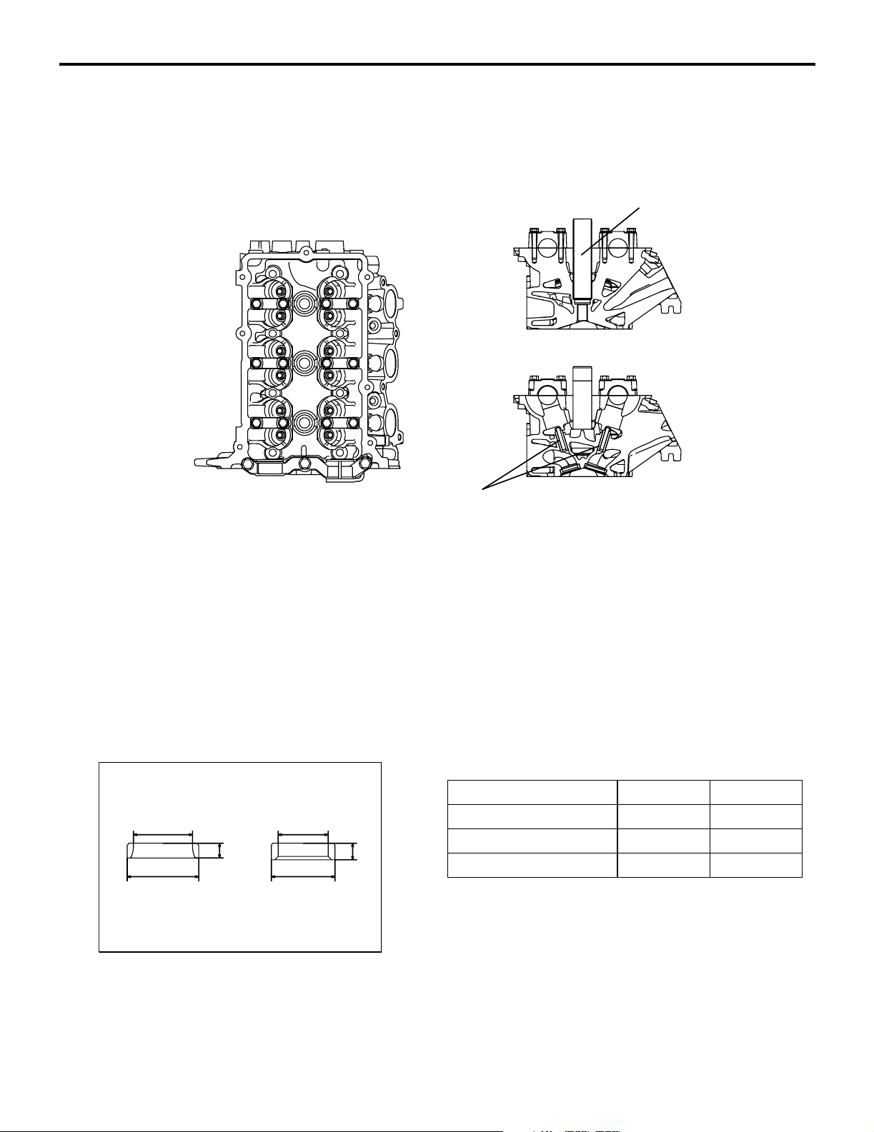
M2112001000325
Spark plug guide
Exhaust
side
Valve guide
The cylinder head is made of aluminum alloy, which
is lightweight and has an excellent cooling efficiency.
The pentroof type combustion chamber has a spark
plug in the center. The valve angle is relatively small,
contributing to size reduction.
The intake and exhaust ports are arranged in a
cross-flow construction. Each cylinder has a pair of
intake ports on one side and a pair of exhaust ports
on the other side.
VALVE SEAT
Intake
side
AK305051
Each of the intake and exhaust camshafts is supported by 4 bearings. On each camshaft, the thrust
load is supported by No. 1 bearing. The No. 1 bearings for the intake and exhaust camshafts have a
common bearing cap.
Sintered alloy valve seat
AB
Intake
d
h
DD
Exhaust
d
AK305052
h
AB
Item Intake Exhaust
D (Outer diameter) mm 31.5 28
d (Inner diameter) mm 26 22
h (height) mm 6.6 7.3
Page 29
11A-4
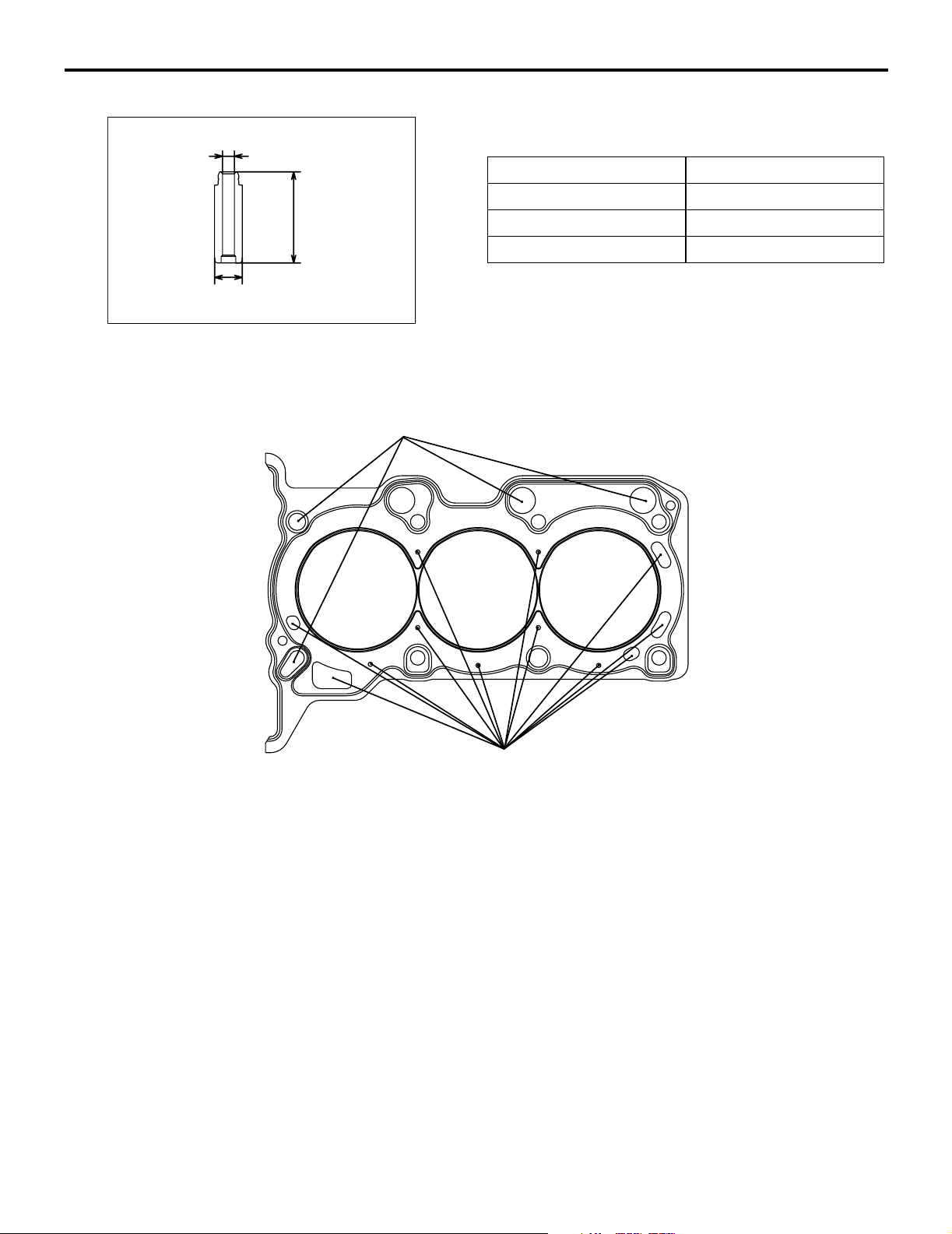
VALVE GUIDE
ENGINE MECHANICAL <134>
BASE ENGINE
The intake and exhaust valves use the same-design
d
valve guide.
Item Specification
D (Outer diameter) mm 10.5
h
d (Inner diameter) mm 4.5
h (height) mm 34.5
D
CYLINDER HEAD GASKET
AK305053
AB
Oil hole
Water hole
The metal gasket having the one layer of wave stopper is used for the cylinder head gasket.
AK305055
AB
Page 30
CYLINDER HEAD COVER
ENGINE MECHANICAL <134>
BASE ENGINE
11A-5
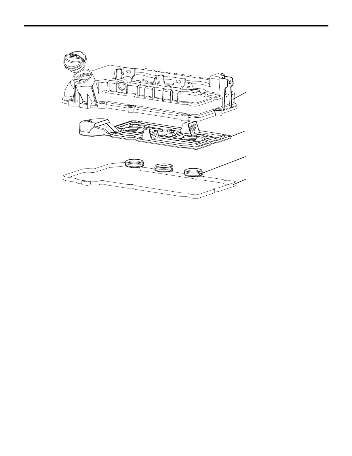
Cylinder head cover
Plate
Oil seal
Cylinder head
cover gasket
A resin cylinder head cover is used for the cylinder
head.
AK305057
AB
The oil plate and the oil seal are integrated with the
cylinder head cover assembly.
Page 31

11A-6
CYLINDER BLOCK
ENGINE MECHANICAL <134>
BASE ENGINE
Right side view
Top view
Front
Front view
Front
Nipple
Under view
Front
Left side view
Front
Thermostat case installation position
Oil filter installation position
The cylinder block is made of lightweight aluminum
alloy.
The crankshaft journal is supported by 4 bearings.
The crankshaft thrust load is supported by No. 3
bearing.
The water jacket is of a full-siamese design.
A nipple is provided at the front of the block to supply
engine oil onto the timing chain.
Rear view
AK305060
AB
Item Dimen
sion
Overall height mm 280
Overall length mm 292.1
Top fac e to c ranksh aft c enter mm 205
Crankshaft center to bottom face mm 75
Bore mm 75
Bore pitch mm 83
Stroke mm 84.8
Page 32

REAR OIL SEAL CASE
A
ENGINE MECHANICAL <134>
BASE ENGINE
The rear oil seal case is a sheet-metal work. The
A-A
case is installed with sealant applied onto the mounting face to prevent oil leakage.
11A-7
PISTON
A
AK305061
AB
The piston is made of special aluminum alloy. Weight
reduction is achieved by minimizing the overall
height while maximizing the recess on both ends of
the piston pin.
The center of the piston pin hole is offset by 0.5 mm
from the center of the piston towards the thrust side.
Front mark
The piston skirt has a streak finish to enhance oil
retention and anti-seizing property.
Item Dimension
Piston pin offset
Base diameter mm 75
Pin diameter mm 18
Overall height mm 46.04
PISTON PIN
AK305063
AC
The piston pin is of a semi-floating type, press-fitted
into the connecting rod small end while capable of
floating relative to the piston.
Item Dimension
d
D
Outer diameter mm 18
Inner diameter mm 11
h
AK305064
AB
Overall length mm 50
Page 33

11A-8
PISTON RING
ENGINE MECHANICAL <134>
BASE ENGINE
Spacer
Piston ring No.1
Piston ring No.2
Oil ring
Rail
Piston ring No.1
Maker mark
Oil ring
Piston ring No.2
AK305365
AB
Each piston is provided with No. 1 and No. 2 compression rings and an oil ring.
Item No. 1 piston ring No. 2 piston ring Oil ring
Shape Barrel Tapered 3-piece
Surface treatment (Contact
Nitride coated Parkerized Hard chrome plated
face with cylinder)
Maker mark R 2R No marking
Page 34

CONNECTING ROD
d
ENGINE MECHANICAL <134>
BASE ENGINE
11A-9
The connecting rod is made of highly rigid, forged
carbon steel. The rod portion has an H-shaped cross
section.
The connecting rod big end bearing is lubricated
through an oil passage running from the main journal
to the crankshaft pin.
Item Dimension
D
d (Small end inner
18
diameter) mm
D (Large end inner
43
diameter) mm
L (Center distance) mm 135.6
L
CONNECTING ROD BEARING
Identification
color
H
AK305066
A
AK305309
AB
AB
The upper and lower connecting rod bearing halves
are identical.
The connecting rod bearing is equipped with back
metal. While the bearing itself is made of aluminum
alloy, the back metal is normally made of steel sheet.
The connecting rod bearing is narrower than the
bearing cap, this is to minimize wear.
Item Dimension
H (Width) mm 13.5
A (Thickness) mm 1.5
Page 35

11A-10
CRANKSHAFT
Crankshaft sensing ring
Oil pump drive
gear shaft
Crankshaft
sprocket
Crankshaft
sprocket B
ENGINE MECHANICAL <134>
BASE ENGINE
Balance weight
Oil hole
Balance weight
Crankshaft
A casted crankshaft is used for the crankshaft.
The crankshaft consists of 4 main bearings and 4
balance weights.
The crankshaft pins are arranged at 120° intervals.
The oil hole supplies lubrication oil from the journal to
the crank pin.
CRANKSHAFT BEARING, THRUST BEARING
Front
Thrust bearing
Groove
AK305069
AB
A crankshaft sprocket, an oil pump drive gear shaft,
and crankshaft sprocket B are press-fitted onto the
front of the crankshaft.
The crankshaft is also fitted with a crankshaft sensing ring.
Upper bearing
Lower bearing
Oil groove
Oil hole
Identification
color
The upper crankshaft bearing (with oil groove) is
located on the cylinder block side while the lower
bearing (without oil groove) is held by the bearing
cap.
Identification
color
AK305071
AB
The crankshaft bearing is equipped with back metal.
While the bearing itself is made of aluminum alloy,
the back metal is made of steel sheet.
A thrust bearing is installed on both sides of the No.
3 crankshaft bearing.
Page 36

CRANKSHAFT PULLEY
ENGINE MECHANICAL <134>
BASE ENGINE
Item Dimensio
Crankshaft bearing Width mm 16
Crankshaft thrust bearing Thickness mm3.275
11A-11
n
Thickness mm20
Timing mark
The crankshaft pulley is made of steel plate. The pulley has grooves to engage with a V-ribbed belt (5
ribs), which drives an alternator and a water pump.
AK305073
AC
An ignition timing mark (notch) is stamped on the
flange of the pulley.
Page 37

11A-12
FLYWHEEL
ENGINE MECHANICAL <134>
BASE ENGINE
Flywheel
Ring gear
The flywheel is made of cast-iron. A separate ring
gear is mounted on it.
AK305074
AB
Page 38

TIMING CHAIN TRAIN
ENGINE MECHANICAL <134>
BASE ENGINE
11A-13
Timing chain mark
link plate (bule)
Camshaft sprocket
timing mark
Camshaft sprocket
Tensioner lever
Timing chain
tensioner
Timing mark
Crankshaft
sprocket
timing mark
Timing mark
Timing chain mark
link plate (bule)
V.V.T. sprocket
timing mark
V.V.T. sprocket
Chain guide
Timing chain mark
link plate (bule)
Crankshaft sprocket
The 2 camshafts are driven by the timing chain via
the respective sprockets.
The timing chain, consisting of 122 links, is an endless chain, connecting the crankshaft sprocket with
the camshaft and V.V.T. sprockets.
The timing chain is equipped with 3 mark link plates
(blue) to correctly time the 3 sprockets with each
other.
The timing chain is tensioned by the timing chain tensioner, which has a built-in plunger with plunger
springs.
Item No. of
teeth
Camshaft sprocket 36
V.V.T. sp ro cket 36
Crankshaft sprocket 18
AK305058
AB
TIMING CHAIN TENSIONER
Coil spring 1
Ball sheet
Ball
Retainer
The plunger in the timing chain tensioner directly
pushes the tension lever, and the pressure automatically adjusts the timing chain tension.
A cam is provided to lock the plunger in place after
the engine stops. This helps prevent the timing chain
from wobbling just after the engine starts.
With the timing chain tensioner installed, do not
crank the engine in the reverse direction. This will
force the plunger to overcome the cam, or even
cause other problems.
Plunger
Pin
Cam
Coil spring 2
AK305388
AB
Page 39

11A-14
VALVE ME CHANISM
Exhaust camshaft
ENGINE MECHANICAL <134>
BASE ENGINE
Spark plug guide
Intake camshaft
Valve tappet
Exhaust valve
The valve mechanism is based on a 4-valve DOHC
(Double Over Head Camshaft) design having the
camshaft on the upper valve. Each cylinder has 2
intake valves and 2 exhaust valves, arranged in a
V-shape pattern.
Intake valve
AK305077
AB
Camshaft rotation is transmitted via valve tappets to
the respective valves which open and close accordingly.
Page 40

VALVE
ENGINE MECHANICAL <134>
BASE ENGINE
11A-15
Intake
DD
L
The valves have heat-resistance. The entire valve
surface is treated with gas nitriding.
VALVE ST EM SEAL
Valve stem seal
Exhaust
d
L
d
Item Intake valve Exhaust valve
Head diameter mm30.5 25.5
Stem diameter mm5.0 5.0
Overall length mm89.61 90.94
The valve stem seal employs springs to enhance
sealing performance, minimizing oil passing down to
the port.
AK305078
AB
VALVE SPRING
AK305079
AB
The valve spring has a dual pitch spring to prevent
surging in the high speed range.
Item Specification
Free length mm 43.1
No. of spring turns 8.49
h
AK300721
AB
Page 41

11A-16
VALVE TAPPET
ENGINE MECHANICAL <134>
Thickness
Identification mark
BASE ENGINE
Valve tappets are available in 31 thicknesses, at 0.02
mm intervals between 2.70 mm and 3.30 mm, to
ensure correct valve clearance.
AK300722
AB
MIVEC (MITSUBISHI INNOVATIVE VALVE TIMING ELECTRONIC CONTROL SYSTEM)
A
V.V.T.sprocket
bolt
A
Oil control valve
Oil control
valve filter
bolt
Cylinder head
Cylinder block
A-A
Oil control
valve filter
AK300856
AB
MIVEC (Mitsubishi Innovative Valve timing Electronic
Control system) consists of the components illustrated above.
The intake valve timing is optimally controlled (continuously variable) under the changing driving conditions to improve power in the entire speed range.
V.V.T. SPROCKET (VARIABLE VALVE TIMING S PROCKET)
Timing mark
Sprocket
Vane housing
Advance oil chamber
Vane roter
Vane bushing
V.V.T.sprocket
bolt
Retard oil chamber
Stopper pin
AK300857
AB
Page 42

ENGINE MECHANICAL <134>
BASE ENGINE
Oil from the oil control valve is sent to the V.V.T.
sprocket, moving the vane rotor and thus regulating
the valve timing.
CAMSHAFT
Intake camshaft
11A-17
Advance
Retard
oil channel
Exhaust camshaft
oil channel
Dowel pin
The lightweight camshaft is achieved by the hollow
design.
Oil channels run through the intake camshaft,
through which oil is sent from the oil control valve to
the V.V.T. sprocket.
A cam position sensing ring is press-fitted onto the
rear portion of the intake camshaft.
Hollow section
Sealing cap
Sensing bean
AK305000
AB
Item Dimensio
n
Overall length mm Intake 324.5
Exhaust 278.9
Journal mm 26
Valve lift mm Intake 8.5
Exhaust 7.6
OIL CONTROL VALVE (OCV)
Spool
Plunger spring
Valve sleeve
Spring guide
Insulation coilar
Pressure
chamber
Drain
Pump
Default
pressure
chamber
Drain
Bobbin
O-ring
Stator
Enameled copper wire
Tape
Bracket
Guide cap
Terminal
Shaft
Plunger
Seal cap
Yoke
AK302997
AB
Page 43

11A-18
ENGINE MECHANICAL <134>
The oil control valve is essentially a solenoid valve,
regulated by the engine-ECU or engine-A-M/T-ECU
signals to feed oil to the V.V.T. sprocket assembly to
move the vane rotor.
TIMING CHAIN CASE
BASE ENGINE
Engine support bracket
The engine support bracket, the oil pump and the
relief valve are integrated as well as water chamber
of the water pump.
AK305244
AB
Page 44

ENGINE MECHANICAL <134>
BASE ENGINE
BALANCER
The 3-cylinder engine has three throws distributed at
equal intervals. The motion of No. 1 and No. 3 pistons generates pitching moment around the No. 2
cylinder. This unbalancing moment is canceled out
by the following system.
The crank webs for No. 1 and No. 3 cylinders are fitted with overbalance weights.
A counterbalance shaft is provided in parallel with
the crankshaft that rotates at the same speed but in
the opposite direction from the crankshaft.
Balancer chain mark
link plate (yellow)
Counter
balance
shaft
A
A
11A-19
The counterbalance shaft is fitted with weights that
are balanced in mass with the overbalance weights
fitted on the No. 1 and No. 3 cylinder crank webs.
The inertia force generated by the pistons and overbalance weights are cancelled out by the counterbalance weights, minimizing the pitching moment.
NOTE: The numbers shown in the drawings indicate
the inertia forces expressed in ratio to "1."
Mark to match with
balancer sprocket
Balancer
shaft sprocket
Balancer
chain
Timing mark
Balance
shaft driven
gear
Counter
balance
shaft
Balance
shaft sprocket
A-A
Balance
shaft drive
gear
The counterbalance shaft is driven by the crankshaft
via crankshaft sprocket B, the balancer chain B, the
balance shaft sprocket, the balance shaft drive gear,
and the balance shaft driven gear.
The balancer chain B, made up of 48 links, is an endless chain, connecting the crankshaft sprocket B with
the balance shaft sprocket.
The balancer chain is provided with a mark link plate
(yellow) at two locations to ensure the sprockets are
timed correctly with each other.
Tensioner B
lever Assy
Crankshaft
sprocket B
Balancer chain mark
link plate (yellow)
Item No. of
Crankshaft sprocket B 22
Balance shaft sprocket 25
Balance shaft drive gear 25
Balance shaft driven gear 22
AK304445
teeth
AC
Page 45

11A-20
BALANCE SHAFT
ENGINE MECHANICAL <134>
BASE ENGINE
Rear view
The cast-iron counterbalance shaft and the integrated driven gear are driven together by the chain
B.
Front view
AK305245
AB
Page 46

11B-1
GROUP 11B
CONTENTS
GENERAL INFORMATION . . . . . . . . 11B-2 BASE ENGINE . . . . . . . . . . . . . . . . . . 11B-2
Page 47

11B-2
ENGINE MECHANICAL <135>
GENERAL INFORMATION
GENERAL INFORMATION
M2112000100415
The unit is powered by the newly developed 135930
/ 135950 engine. The total displacement is 1.3L for
the 135930, and 1.5L for the 135950. Both engines
are a 4-cylinder 16-valve DOHC (Double Over Head
Camshaft) design.
The engine family has the following features.
MAJOR SPECIFICATIONS
Item 135930 135950
Total displa cemen t mL 1,332 1 ,49 9
Bore × Stroke mm 75 × 75.4 75 × 84.8
Compression ratio 10.5
Compression chamber Pentroof-type
Valve tim ing Intake op eni ng BT DC 41° − ATDC 9° BTDC 41° − ATDC 9°
Intake closing ABDC 3° − ABDC 53° ABDC 11° − ABDC 61°
• Aluminum cylinder block
• MIVEC (Mitsubishi Innovative Valve timing Elec-
tronic Control system)
• Selective valve tappet of direct acting valve system for valve clearance adjustment
• Timing chain
Exhaust opening BBDC 35° BBDC 39°
Exhaust closing ATDC 5° ATDC 5°
Maximum output kW (PS)/rpm 70 (95)/6,000 80 (109)/6,000
Maximum torque Nm (kgm)/rpm 125 (12.7)/4,000 145 (14.8)/4,000
Fuel system Electronically controlled multipoint fuel injection
Ignition system Electronic-controlled 4-coil
BASE ENGINE
M2112001000336
CYLINDER HEAD
The cylinder head is made of aluminum alloy, which
is lightweight and has an excellent cooling efficiency.
The pentroof type combustion chamber has a spark
plug in the center. The valve angle is relatively small,
contributing to size reduction.
The intake and exhaust ports are arranged in a
cross-flow construction. Each cylinder has a pair of
intake ports on one side and a pair of exhaust ports
on the other side.
Each of the intake and exhaust camshafts is supported by 5 bearings. On each camshaft, the thrust
load is supported by No. 1 bearing. The No. 1 bearings for the intake and exhaust camshafts have a
common bearing cap.
Page 48

ENGINE MECHANICAL <135>
BASE ENGINE
Spark plug guide
11B-3
VALVE SEAT
Intake
DD
Exhaust
side
d
Intake
side
Valve guide
AK305050
AB
Sintered alloy valve seat
Item Intake Exhaust
Exhaust
d
h
h
D (Outer
diameter) mm
d (Inner
31.5 28
26 22
diameter) mm
h (height) mm 6.6 7.3
VALVE GUI DE
AK305052
AB
The intake and exhaust valves use the same-design
d
valve guide.
Item Intake
D (Outer diameter) mm 10.5
h
d (Inner diameter) mm 4.5
h (height) mm 34.5
D
AK305053
AB
Page 49

11B-4
CYLINDER HEAD GASKET
ENGINE MECHANICAL <135>
BASE ENGINE
Oil hole
Water hole
The metal gasket having the one layer of wave stopper is used for the cylinder head gasket.
CYLINDER HEAD COVER
Water hole
AK305054
Cylinder head cover
Plate
Oil seal
AB
A resin cylinder head cover is used for the cylinder
head.
Cylinder head
cover gasket
AK305056
AB
The oil plate and the oil seal are integrated with the
cylinder head cover assembly.
Page 50

CYLINDER BLOCK
ENGINE MECHANICAL <135>
BASE ENGINE
11B-5
Right side view
Top view
Front
Front view
Front
Nipple
Under view
Front
Left side view
Front
Thermostat case installation position
Oil filter installation position
The cylinder block is made of lightweight aluminum
alloy.
The crankshaft journal is supported by 5 bearings.
The crankshaft thrust load is supported by No. 4
bearing.
The water jacket is of a full-siamese design.
A nipple is provided at the front of the block to supply
engine oil onto the timing chain.
Rear view
AK305059
AB
Item Dimen
sion
Overall height mm 280
Overall length mm 375.1
Top fac e to cranks haft cent er mm 2 05
Crankshaft center to bottom face mm 75
Bore mm 75
Page 51

11B-6
ENGINE MECHANICAL <135>
Item Dimen
sion
Bore pitch mm 83
Stroke mm 135930 75.4
135950 84.8
REAR OIL SEAL CASE
A
A-A
BASE ENGINE
The rear oil seal case is a sheet-metal work. The
case is installed with sealant applied onto the mounting face to prevent oil leakage.
PISTON
A
<135930>
AK305061
AB
Piston pin offset
<135950>
Front mark
Piston pin offset
The piston is made of special aluminum alloy. Weight
reduction is achieved by minimizing the overall
height while maximizing the recess on both ends of
the piston pin.
The center of the piston pin hole is offset by 0.5 mm
from the center of the piston towards the thrust side.
The piston skirt has a streak finish to enhance oil
retention and anti-seizing property.
AK305280
AB
Item Dimension
Base diameter mm 75
Pin diameter mm 18
Overall height mm135930 50.46
135950 46.04
Page 52

PISTON PIN
ENGINE MECHANICAL <135>
BASE ENGINE
The piston pin is of a semi-floating type, press-fitted
into the connecting rod small end while capable of
floating relative to the piston.
11B-7
PISTON RING
d
D
D (Outer diameter) mm 18
d (Inner diameter) mm 11
Item Dimension
h
AK305064
Piston ring No.1
Piston ring No.2
AB
h (Overall length) mm 50
Piston ring No.1
Maker mark
Oil ring
Piston ring No.2
Oil ring
Spacer
Rail
Each piston is provided with No. 1 and No. 2 compression rings and an oil ring.
Item No. 1 piston ring No. 2 piston ring Oil ring
Shape Barrel Tapered 3-piece
Surface treatment (Contact
Nitride coated Parkerized Hard chrome plated
face with cylinder)
Maker mark R 2R No marking
AK305365
AB
Page 53

11B-8
CONNECTING ROD
ENGINE MECHANICAL <135>
BASE ENGINE
The connecting rod is made of highly rigid, forged
carbon steel. The rod portion has an H-shaped cross
section.
The connecting rod big end bearing is lubricated
through an oil passage running from the main journal
to the crankshaft pin.
d
L
CONNECTING ROD BEARING
Identification
color
H
D
AK305065
A
AK305309
AB
AB
Item Dimension
d (Small end inner diameter) mm 18
D (Large end inner diameter) mm 43
L (Center
distance) mm
135930 140.3
135950 135.6
The upper and lower connecting rod bearing halves
are identical.
The connecting rod bearing is equipped with back
metal. While the bearing itself is made of aluminum
alloy, the back metal is normally made of steel sheet.
The connecting rod bearing is narrower than the
bearing cap, this is to minimize wear.
Item Dimension
H (Width) mm 13.5
A (Thickness) mm 1.5
Page 54

CRANKSHAFT
ENGINE MECHANICAL <135>
BASE ENGINE
11B-9
<135930>
<135950>
Crankshaft sensing ring
Oil pump drive
gear shaft
Crankshaft
sprocket
Crankshaft
Balance weight
Crankshaft sensing ring
Oil pump drive
gear shaft
Crankshaft
sprocket
Crankshaft
Balance weight
Oil hole
Balance weight
Oil hole
A casted crankshaft is used for the crankshaft.
The crankshaft consists of 5 main bearings and 4
balance weights for 135930 or consists of 5 main
bearings and 8 balance weights for 135950.
The crankshaft pins are arranged at 180° intervals.
Balance weight
The oil hole supply lubrication oil from the journal to
the crank pin.
A crankshaft sprocket and an oil pump drive gear
shaft are press-fitted onto the front of the crankshaft.
The crankshaft is also fitted with a crankshaft sensing ring.
Oil hole
Oil hole
Balance weight
Balance weight
AK305281
AB
Page 55

11B-10
ENGINE MECHANICAL <135>
BASE ENGINE
CRANKSHAFT BEARING, THRUST BEARING
Front
Thrust bearing
Groove
The upper crankshaft bearing (with oil groove) is
located on the cylinder block side while the lower
bearing (without oil groove) is held by the bearing
cap.
The crankshaft bearing is equipped with back metal.
While the bearing itself is made of aluminum alloy,
the back metal is made of steel sheet.
A thrust bearing is installed on both sides of the No.
4 crankshaft bearing.
Upper bearing
Lower bearing
Oil groove
Oil hole
Identification
color
Identification
color
AK305070
AB
Item Dimen
sion
Crankshaft bearing Width mm 16
Thickness mm20
Crankshaft thrust
bearing
Thickness mm135930 3.275
135950 3.275
CRANKSHAFT PULLEY
<135930>
Timing mark
A steel billet crankshaft pulley is used for 135930.
The pulley has grooves to engage with a V-ribbed
belt (5 ribs), which drives an alternator and a water
pump.
<135950>
Rubber
Timing mark
AK305282
AB
An ignition timing mark (notch) is stamped on the
flange of the pulley.
Page 56

ENGINE MECHANICAL <135>
BASE ENGINE
The crankshaft pulley for 135950 is equipped with a
torsional damper to minimize the torsional vibration
of the crankshaft as well as substantially reduce
noise and vibration at the high speed range.
FLYWHEEL
Flywheel
11B-11
Ring gear
The flywheel is made of cast-iron. A separate ring
gear is mounted on it.
AK305074
AB
Page 57

11B-12
TIMING CHAIN TRAIN
ENGINE MECHANICAL <135>
BASE ENGINE
Timing chain mark
link plate (bule)
Camshaft sprocket
timing mark
Camshaft sprocket
Tensioner lever
Timing chain
tensioner
Timing mark
Crankshaft
sprocket
timing mark
Timing mark
Timing chain mark
link plate (bule)
V.V.T. sprocket
timing mark
V.V.T. sprocket
Chain guide
Timing chain mark
link plate (bule)
Crankshaft sprocket
The 2 camshafts are driven by the timing chain via
the respective sprockets.
The timing chain, consisting of 122 links, is an endless chain, connecting the crankshaft sprocket with
the camshaft and V.V.T. sprockets.
The timing chain is equipped with 3 mark link plates
(blue) to correctly time the 3 sprockets with each
other.
The timing chain is tensioned by the timing chain tensioner, which has a built-in plunger with plunger
springs.
Item No. of
teeth
Camshaft sprocket 36
V.V.T. sp rocke t 36
Crankshaft sprocket 18
AK305075
AB
TIMING CHAIN TENSIONER
Coil spring 1
Ball sheet
Ball
Retainer
The plunger in the timing chain tensioner directly
pushes the tension lever, and the pressure automatically adjusts the timing chain tension.
A cam is provided to lock the plunger in place after
the engine stops. This helps prevent the timing chain
from wobbling just after the engine starts.
With the timing chain tensioner installed, do not
crank the engine in the reverse direction. This will
force the plunger to overcome the cam, or even
cause other problems.
Plunger
Pin
Cam
Coil spring 2
AK305388
AB
Page 58

VALVE MEC HANI SM
Exhaust camshaft
ENGINE MECHANICAL <135>
BASE ENGINE
Spark plug guide
11B-13
Intake camshaft
Valve tappet
Exhaust valve
The valve mechanism is based on a 4-valve DOHC
(Double Over Head Camshaft) design having the
camshaft on the upper valve. Each cylinder has 2
intake valves and 2 exhaust valves, arranged in a
V-shape pattern.
VALVE
Intake
DD
d
Intake valve
AK305076
AB
Camshaft rotation is transmitted via valve tappets to
the respective valves which open and close accordingly.
Exhaust
d
L
The valves have heat-resistance. The entire valve
surface is treated with gas nitriding.
L
AK305078
AB
Item Intake valve Exhaust valve
Head diameter mm30.5 25.5
Stem diameter mm5.0 5.0
Overall length mm89.61 90.94
Page 59

11B-14
VALVE STE M SE AL
Valve stem seal
ENGINE MECHANICAL <135>
BASE ENGINE
The valve stem seal employs springs to enhance
sealing performance, minimizing oil passing down to
the port.
VALVE SPR ING
VALVE TAPP ET
h
Thickness
AK305079
AK300721
AB
The valve spring has a dual pitch spring to prevent
surging in the high speed range.
Item Specification
Free length mm 43.1
No. of spring turns 8.49
AB
Valve tappets are a vaila ble in 31 t hickn esses , at 0.02
mm intervals between 2.70 mm and 3.30 mm, to
ensure correct valve clearance.
Identification mark
AK300722
AB
Page 60

ENGINE MECHANICAL <135>
BASE ENGINE
11B-15
MIVEC (MITSUBISHI INNOVATIVE VALVE TIMING ELECTRONIC CONTROL SYSTEM)
A
V.V.T.sprocket
bolt
A
MIVEC (Mitsubishi Innovative Valve timing Electronic
Control system) consists of the components illustrated above.
Oil control valve
Oil control
valve filter
bolt
Cylinder head
Cylinder block
The intake valve timing is optimally controlled (continuously variable) under the changing driving conditions to improve power in the entire speed range.
V.V.T. SPROCKET (VARIABLE VALVE TIMING SPROCKET)
A-A
Oil control
valve filter
AK300856
AB
Timing mark
Sprocket
Oil from the oil control valve is sent to the V.V.T.
sprocket, moving the vane rotor and thus regulating
the valve timing.
Vane housing
Advance oil chamber
Vane roter
Vane bushing
V.V.T.sprocket
bolt
Retard oil chamber
Stopper pin
AK300857
AB
Page 61

11B-16
CAMSHAFT
ENGINE MECHANICAL <135>
BASE ENGINE
Intake camshaft
Advance
Retard
oil channel
Exhaust camshaft
oil channel
Dowel pin
The lightweight camshaft is achieved by the hollow
design.
Oil channels run through the intake camshaft,
through which oil is sent from the oil control valve to
the V.V.T. sprocket.
A cam position sensing ring is press-fitted onto the
rear portion of the intake camshaft.
Cam positon sensing ring
Hollow section
Sealing cap
AK304999
AB
Item Dimen
sion
Overall length mm Intake 407.5
Exhaust 361.9
Journal mm 26
Valve lift mm I ntake 135930 7.9
OIL CONTROL VALVE (OCV)
Insulation coilar
Spool
Plunger spring
Valve sleeve
Spring guide
Pressure
chamber
Drain
The oil control valve is essentially a solenoid valve,
regulated by the engine-ECU or engine-A-M/T-ECU
Default
pressure
chamber
Pump
135950 8.4
Exhaust 135930 7.6
135950 7.9
Bobbin
Drain
O-ring
Stator
Enameled copper wire
Tape
Bracket
Guide cap
Terminal
Shaft
Plunger
Seal cap
Yoke
AK302997
signals to feed oil to the V.V.T. sprocket assembly to
move the vane rotor.
AB
Page 62

TIMING CHAIN CASE
ENGINE MECHANICAL <135>
BASE ENGINE
Engine support bracket
11B-17
The engine support bracket, the oil pump and the
relief valve are integrated as well as water chamber
of the water pump.
AK305243
AB
Page 63

GROUP 12
CONTENTS
12-1
GENERAL INFORMATION . . . . . . . . 12-2
OIL PUMP . . . . . . . . . . . . . . . . . . . . . 12-3
RELIEF VALVE . . . . . . . . . . . . . . . . . 12-3
OIL SCREEN . . . . . . . . . . . . . . . . . . . 12-4
OIL FILTER. . . . . . . . . . . . . . . . . . . . . 12-4
OIL PAN . . . . . . . . . . . . . . . . . . . . . . . 12-5
OIL LEVEL GAUGE, OIL FILLER CAP, OIL
DRAIN PLUG . . . . . . . . . . . . . . . . . . . 12-6
Page 64

12-2
GENERAL INFORMATION
LUBRICATION SYSTEM SCHEMATIC
ENGINE LUBRICATION
GENERAL INFORMATION
M2120000100034
Oil screen
Oil pump
Relief valve
Oil pressure switch
Cylinder head
oil passage
No.1 Camshaft
journal
Intake camshaft
journal
Timing chain case
oil passage
Cylinder block
oil passage(right side)
Oil filter
Cylinder block
oil passage
(main gallery)
Crankshaft
journal
Crankshaft
pin
Exhaust camshaft
journal
Counter balance shaft
rear journal
Oil pan
The lubrication system employs a full-flow filtering
and forced feeding. Oil in the oil pan is sucked by the
oil pump which then sends out oil at pressure regulated by the relief valve, through the oil filter and to
the cylinder block. From there, oil flow is divided into
the passage to the crankshaft journals and that to the
cylinder head.
AK305366
AB
From the crankshaft journals, oil flows to the crank
pins. From the cylinder head, oil flows to the camshaft journals.
Page 65

ENGINE LUBRICATION
OIL PUMP
OIL PUMP
12-3
M2120002000011
A
A
The oil pump is of a cycloid type, directly driven by
the crankshaft.
Specifically, oil is sucked into the expanding space
and is pushed out from the shrinking space.
Timing chain case
Machine screw
Cover
On the cycloid oil pump, as the inner rotor is rotated
by the crankshaft, the outer rotor also rotates. The
resultant change in spatial volumes between the
rotors generates pumping action.
Item Specification
Type Cycloid pump
No. of lobes Inner rotor 10
A-A
Oil seal
Oil pump
inner rotor
Oil pump
outer rotor
AK305367
AB
Outer rotor 11
Displacement L/min(6,000 r/min.) 35
RELIEF VALVE
A
A
The relief valve is of a plunger type. The valve regulates the maximum pressure of lubrication oil being
sent to the engine.
When the pressure of oil from the oil pump exceeds
the specified value, the valve opens to relieve the
excess flow.
The excess oil is returned to the suction side of the
oil pump.
A-A
Timing chain case
Relief plunger
Relief spring
Plug
AK305369
M2120003000014
AB
Page 66

12-4
OIL SCREEN
Timing chain case
ENGINE LUBRICATION
OIL SCREEN
M2120004000017
The oil screen is located in the position with the least
disturbance to the oil suction volume that results
from oil level variation in the oil pan while the vehicle
is driven.
Oil screen
Element
Oil filter
Oil pan
AK305372
AK305373
AB
OIL FILTER
The oil filter is mounted onto the cylinder block.
Item Specification
Filtering method Full-flow filtering, Paper
Filtration area cm
Rated flow L/min. 25
AB
M2120005000010
element
2
750
Page 67

<134>
<135>
ENGINE LUBRICATION
OIL PAN
OIL PAN
Oil drain plug
installation side
12-5
M2120006000013
Oil drain plug
installation side
The oil pan, located below the engine, is made of
sheet metal.
AK305283
AB
Page 68

12-6
OIL LEVEL GAUGE, OIL FILLER CAP, OIL DRAIN PLUG
ENGINE LUBRICATION
OIL LEVEL GAUGE, OIL FILLER CAP, OIL DRAIN PLUG
M2120007000016
<134>
<135>
Oil level gauge
Oil filler cap
Oil drain plug
Oil level gauge
Oil drain plug
The oil level gauge, oil filler cap, and oil drain plug
are all located in the front of the engine for excellent
serviceability.
Oil filler cap
AK305389
AB
Page 69

GROUP 13
CONTENTS
MULTIPOINT FUEL INJECTION (MPI). . . . . . . . . . . . . . . . . . . . 13A
FUEL SUPPLY . . . . . . . . . . . . . . . . . . . . . . . . . . . . . . . . . . . . . . 13B
13-1
Page 70

GROUP 13A
CONTENTS
13A-1
GENERAL INFORMATION . . . . . . . . 13A-2
CONTROL SYSTEM . . . . . . . . . . . . . 13A-7
SENSOR. . . . . . . . . . . . . . . . . . . . . . . 13A-8
ACTUATOR . . . . . . . . . . . . . . . . . . . . 13A-14
FUEL INJECTION CONTROL . . . . . . 13A-15
THROTTLE VALVE OPENING ANGLE
CONTROL . . . . . . . . . . . . . . . . . . . . . 13A-23
IGNITION TIMING AND DISTRIBUTION
CONTROL . . . . . . . . . . . . . . . . . . . . . 13A-25
MIVEC (Mitsubishi Innovative Valve timing
Electronic Control system) . . . . . . . 13A-31
POWER SUPPLY CONTROL. . . . . . . 13A-39
FUEL PUMP RELAY CONTROL . . . . 13A-40
OXYGEN SENSOR HEATER CONTROL
. . . . . . . . . . . . . . . . . . . . . . . . . . . . . . . . .
. . . . . . . . . . . . . . . . . . . . . . . . . . . . . . . . . 13A-41
. . . . . . . . . . . . . . . . . . . . . . . . . . . . . . . . . . . . . . . . . . . . . . . . . . . . . . . . . . . . . . . . . .
A/C COMPRESSOR CONTROL. . . . . 13A-42
ALTERNATOR CONTROL . . . . . . . . . 13A-43
STARTER RELAY CONTROL . . . . . . 13A-44
CONTROLLER AREA NETWORK (CAN)
. . . . . . . . . . . . . . . . . . . . . . . . . . . . . . . . .
. . . . . . . . . . . . . . . . . . . . . . . . . . . . . . . . . 13A-44
. . . . . . . . . . . . . . . . . . . . . . . . . . . . . . . . . . . . . . . . . . . . . . . . . . . . . . . . . . . . . . . . . .
DIAGNOSIS SYSTEM. . . . . . . . . . . . . 13A-45
Page 71

13A-2
MULTIPOINT FUEL INJECTION (MPI)
GENERAL INFORMATION
GENERAL INFORMATION
The engine control system consists of sensors that
detect the conditions of the engine and the actuators
that operate under the control of the engine-ECU or
engine automated manual transmission electronic
control unit (engine-A-M/T-ECU), which calculates
and determines the engine control contents based
on the signals provided by the sensors. The
engine-ECU or engine-A-M/T-ECU effects fuel injec-
M2132000100428
tion control, idle speed control, ignition timing control,
and fuel pump control. In addition, the engine-ECU
or engine-A-M/T-ECU contains a self-diagnosis system to facilitate the diagnosis of malfunctions in the
major sensors and actuators.
Page 72

System Block Diagram
MULTIPOINT FUEL INJECTION (MPI)
GENERAL INFORMATION
13A-3
Manifold absolute pressure
sensor
Intake air temperature sensor
Engine coolant temperature
sensor
Accelerator pedal position
sensor (main)
Throttle position sensor (sub)
Crank angle sensor
Camshaft position sensor
Detonation sensor
Oxygen sensor (front)
Oxygen sensor (rear)
Engine-ECU or engine-A-M/T-ECU
[1] Fuel injection control
[2] Throttle valve opening control
and idle speed control
[3] Ignition timing control
[4] MIVEC (Mitsubushi Innovative
Valve timing Electronic Control
system)
[5] Power supply control
(Power supply to sensor,
actuator)
[6] Fuel pump relay control
[7] Oxygen sensor heater
control
No. 1 injector
No. 2 injector
No. 3 injector
No. 4 injector <135 engine>
No. 1 ignition coil
No. 2 ignition coil
No. 3 ignition coil
No. 4 ignition coil <135 engine>
Engine control relay
Starter relay
Fuel pump relay
Ignition switch-IG
Ignition switch-ST
Power supply
Alternator FR terminal
Throttle valve contorol servo
power supply
Throttle position sensor (main)
Accelerator pedal position
sensor (sub)
[8] A/C compressor control
[10] Alternator control
[11] Starter relay control
[12] Purge control
[11] Diagnostic output
[12] RAM data transmission
Throttle valve control servo
relay
Oxygen sensor heater (front)
Oxygen sensor heater (rear)
A/C compressor
Oil control valve (for MIVEC)
Purge control solenoid valve
Alternator G terminal
Throttle valve control servo
(DC motor)
AK304661
AB
Page 73

13A-4
Control System Diagram
MULTIPOINT FUEL INJECTION (MPI)
GENERAL INFORMATION
1 Oxygen sensor (rear)
2 Oxygen sensor (front)
3 Crank angle sensor
4 Camshaft position
sensor
5 Detonation sensor
6 Engine coolant
temperature sensor
7 Manifold absolute
pressure sensor
8 Intake air temperature
sensor
9 Throttle position
sensor (main)
10 Throttle position
sensor (sub)
Power supply
Ignition switch-IG
Ignition switch-ST
Oil pressure switch
Alternator FR
terminal
Accelerator pedal
position sensor
(main)
Accelerator pedal
position sensor
(sub)
8 Intake air temperature
sensor
7 Manifold absolute
pressure sensor
EngineECU
or engineA-M/TECU
1 Oil control valve
2 Injector
3 Throttle valve
control servo
4 Purge control
solenoid valve
9 Throttle position sensor (main)
10 Throttle position sensor (sub)
3 Throttle valve
control servo
Engine control relay
Fuel pump relay
Throttle valve
control servo relay
Starter relay
Ignition coil
Alternator G terminal
Oxygen sensor heater
A/C compressor
Air
From fuel
pump
3 Crank angle sensor
1 Oxygen sensor (rear)
Catalytic
converter
2 Oxygen sensor (front)
1 Oil control valve
List of Components and Functions
Name Function
ECU Engine-ECU or
engine-A-M/T-ECU
Effects control to actuate the actuators in accordance with the driving
conditions, based the signals input by the sensors.
4 Camshaft
position sensor
2 Injector
6 Engine coolant
temperature sensor
5 Detonation sensor
Canister
4 Purge control
solenoid valve
AK304662
AB
Page 74

MULTIPOINT FUEL INJECTION (MPI)
GENERAL INFORMATION
Name Function
Sensors Ignition switch-IG Detects the ignition switch-IG ON/OFF signals. The engine-ECU or
engine-A-M/T-ECU turns the engine control relay ON/OFF in
accordance with these signals.
Ignition switch-ST Detects that the engine is cranking. Based on this signal, the
engine-ECU or engine-A-M/T-ECU effects fuel injection and ignition
timing control that are suited for starting the engine.
Manifold absolute
pressure sensor
Contains a piezoelectric resistor semiconductor pressure sensor to
detect the pressure in the intake manifold. The engine-ECU or
engine-A-M/T-ECU uses the voltage that is output by this sensor to
calculate the ignition timing. Furthermore, it estimates the
atmospheric pressure when the ignition switch is ON (with the engine
stopped) and the throttle is fully open.
13A-5
Oxygen sensors (front
and rear)
Intake air temperature
sensor
Engine coolant
temperature sensor
Throttle position sensors
(main and sub)
Accelerator pedal
position sensors (main
and sub)
Camshaft position
sensor
Crank angle sensor Contains a magnetic resistance element to detect the crank angle.
Consisting of zirconia and platinum electrodes, these sensors detect
the oxygen concentration in the exhaust gases. The engine-ECU or
engine-A-M/T-ECU effects air-fuel ratio feedback control based on
the oxygen sensor (front) output signals. In addition, it uses the
signals output by the oxygen sensor (rear) to correct the deviations in
the output signals resulting from the deterioration of the oxygen
sensor (front).
Contains a thermistor to detect the intake air temperature. Based on
the voltage that is output by this sensor, the engine-ECU or
engine-A-M/T-ECU corrects the fuel injection volume to suit the intake
air temperature.
Contains a thermistor to detect the engine coolant temperature. The
engine-ECU or engine-A-M/T-ECU determines the warm-up condition
of the engine based on the signals output by this sensor, and controls
the fuel injection volume, idle speed, and ignition timing.
Detect the position of the throttle valve and input it into the
engine-ECU or engine-A-M/T-ECU. Based on the voltage output by
these sensors, the engine-ECU or engine-A-M/T-ECU effects
feedback control for the throttle valve position.
Detect the position of the accelerator pedal and input it into the
engine-ECU or engine-A-M/T-ECU. Based on the voltage output by
these sensors, the engine-ECU or engine-A-M/T-ECU injects fuel in
accordance with the accelerator pedal position and effects throttle
valve position control.
Contains a magnetic resistance element to detect the position of the
camshaft. The engine-ECU or engine-A-M/T-ECU detects the
compression top-dead-centre (TDC) of each cylinder based on the
combination of the signals from this sensor and the crank angle
sensor.
Based on this signal, the engine-ECU or engine-A-M/T-ECU controls
the injectors.
Detonation sensor Contains a piezoelectric element to detect the vibration of the cylinder
block during knocking. In accordance with the signals provided by this
sensor, the engine-ECU or engine-A-M/T-ECU retards the ignition
timing in accordance with the extent of the knocking.
Alternator FR terminal Detects the energizing duty cycle ratio at the alternator field coil.
Page 75

13A-6
Name Function
Actuators Engine control relay In accordance with the signals provided by the engine-ECU or
Throttle valve control
servo relay
Starter relay Controls the power supply for the starter S terminal circuit.
Injectors Inject fuel in accordance with the actuation signals provided by the
Ignition coil (integrated
in power transistor)
Fuel pump relay Controls the actuation of the fuel pump.
Throttle valve control
servo
Oil control valve The signals from the engine-ECU or engine-A-M/T-ECU actuate the
Oxygen sensor heater Controls the current applied to the oxygen sensor heater circuit in
MULTIPOINT FUEL INJECTION (MPI)
GENERAL INFORMATION
engine-A-M/T-ECU, this relay controls the power supply for the
engine-ECU or engine-A-M/T-ECU, crank angle sensor, camshaft
position sensor, and injectors.
Turns the power supply circuit in the engine-ECU or
engine-A-M/T-ECU for actuating the throttle valve control servo
ON/OFF.
engine-ECU or engine-A-M/T-ECU.
Interrupts the primary current of the ignition coil in accordance with
the ignition signal provided by the engine-ECU or engine-A-M/T-ECU,
in order to generate high voltage for ignition.
Controls the position of the throttle valve in accordance with the
signals provided by the engine-ECU or engine-A-M/T-ECU.
oil control valve, which controls the valve timing.
accordance with the signals from the engine-ECU or
engine-A-M/T-ECU.
Purge control solenoid
valve
Alternator G terminal In accordance with the signals provided by the engine-ECU or
A/C compressor Actuates the A/C compressor in accordance with the signals provided
In accordance with the signals provided by the engine-ECU or
engine-A-M/T-ECU, this valve controls the volume of the purge air
that enters the surge tank.
engine-A-M/T-ECU, this terminal controls the amount of current
generated by the alternator.
by the A/C-ECU via Controller Area Network (CAN) communication.
Page 76

MULTIPOINT FUEL INJECTION (MPI)
CONTROL SYSTEM
Engine-ECU or Engine-A-M/T-ECU
Engine-ECU or engine-A-M/T-ECU
CONTROL SYSTEM
Microprocessor
13A-7
M2132000500028
Input
sensor
In accordance with the data input by the sensors, the
engine-ECU or engine-A-M/T-ECU determines (calculates) optimal control and actuates the output actuators to suit the constantly changing driving
conditions.
The engine-ECU or engine-A-M/T-ECU consists of a
32-bit microprocessor, random access memory
(RAM), read only memory (ROM), and input-output
(I/O interface).
Input
interface
RAM
ROM
It has adopted a rewritable flash-memory ROM in
which the control data can be changed or corrected
through the use of a special tool. In addition, it has
adopted an electrically erasable programmable read
only memory (EEP ROM) so that the learned correction data will not be deleted even if the battery is disconnected.
Furthermore, the engine-A-M/T-ECU that is used on
the automated manual transmission vehicles effects
integrated control of the engine and the transmission.
ECU Connector Input / Output Pin Arrangement
EEP
ROM
Output
interface
Output
actuator
AK305521
AB
Engine-ECU or engine-A-M/T-ECU Connector
A-08 A-09
93
108
123
109
124
8078 79 8182
9594R9697
110
111
112
125
126
127
83
98
113
128
868485
8788 919089
99
101100 102103104105106
114
115
116
117
129
130
131
132
118
133
119
134
120
121
135
136
AK304702
8
9
1
3
5
7
2
4
6
22
37
52
23
38
53
24
39 40
54 55
12
13
11
10
27
25
26
L
4142
5756
43284445
58
14
29
30
6059
1615
31
46
61
17
18
33
32
4748
6362
19
34
49
64
21
20
36
35
5051
6665
71 72
737674
75
77
92
107
122
7Throttle valve control servo (+) 56Intake air temperature sensor
8No. 1 injector 75Ground
9No. 2 injector 76Ground
10 No. 1 ignition coil 77 Power supply
12 Camshaft position sensor 78 Throttle valve control servo power supply
13 Crank angle sensor 79 Oxygen sensor heater (front)
AB
Page 77

13A-8
14 Engine coolant temperature sensor 80 Ignition switch-ST
15 Throttle position sensor (main) 81 Fuel pump relay
16 Throttle position sensor (sub) 82 Backup power supply
17 Manifold absolute pressure sensor 83 Accelerator pedal position sensor (main)
20 Detonation sensor (+) 84 Accelerator pedal position sensor (main)
21 Detonation sensor (−)85Accelerator pedal position sensor (main)
22 Throttle valve control servo (−)86Accelerator pedal position sensor (sub) power
23 No. 3 injector 87 Accelerator pedal position sensor (sub)
24 No. 4 injector <135 engine> 88 Accelerator pedal position sensor (sub)
25 No. 2 ignition coil 92 Power supply
27 Camshaft position sensor ground 93 Throttle valve control servo ground
28 Crank angle sensor ground 94 Oxygen sensor heater (rear)
29 Engine coolant temperature sensor ground 97 Oxygen sensor (front)
MULTIPOINT FUEL INJECTION (MPI)
SENSOR
ground
power supply
supply
ground
30 Throttle position sensor ground 98 Oxygen sensor (front) ground
31 Throttle position sensor power supply 99 Oxygen sensor (rear) ground
32 Manifold absolute pressure sensor power
supply
33 Manifold absolute pressure sensor ground 105 CAN Hi
38 Purge control solenoid valve 106 CAN Lo
39 A/C compressor 107 Engine control relay
40 No. 3 ignition coil 108 Throttle valve control servo ground
50 Oil pressure switch 122 Ignition switch-IG
52 Oil control valve 123 Throttle valve control servo relay
53 Alternator G terminal 125 Starter relay
54 Alternator FR terminal 136 Flash EEP ROM data rewriting power supply
55 No. 4 ignition coil <135 engine>
100 Oxygen sensor (rear)
SENSOR
M2132001000219
MANIFOLD ABSOLUTE PRESSURE
(MAP) SENSOR
AK305246
Page 78

MULTIPOINT FUEL INJECTION (MPI)
SENSOR
13A-9
The manifold absolute pressure (MAP) sensor, which
is mounted on the intake manifold, inputs a voltage
that corresponds to the intake manifold pressure into
the engine-ECU or engine-A-M/T-ECU.
The engine-ECU or engine-A-M/T-ECU calculates
and determines the basic fuel injection duration
based on this output voltage and the engine speed.
Furthermore, it converts the voltage that is output by
the sensor when ignition switch is ON (with the
engine stopped) and the throttle fully open into
atmospheric pressure and uses this value for various
types of calculations.
Output voltage
Output voltage
Intake air temperature
AK305303
AB
The diagram describes the characteristics of this
sensor.
ENGINE COOLANT TEMPERATURE SENSOR
Intake manifold pressure
AK305302AB
The diagram describes the characteristics of this
sensor.
INTAKE AIR TEMPERATURE SENSOR
Sensing part of
intake air temperature sensor
AK305246
The intake air temperature sensor, which is built into
the manifold absolute pressure (MAP) sensor,
detects the intake air temperature through the
changes in the resistance of its thermistor.
The engine-ECU or engine-A-M/T-ECU detects the
intake air temperature based on this output voltage
and corrects the fuel injection volume to suit the
intake air temperature.
AB
Heat sensor
(with built-in thermistor)
AK305690
AB
The engine coolant temperature sensor, which is
mounted on the cylinder head, detects the temperature of the engine coolant through the changes in the
resistance of its thermistor.
The engine-ECU or engine-A-M/T-ECU appropriately
controls the fuel injection volume, idle speed, and the
ignition timing when the engine is cold, in accordance with this output voltage.
Output voltage
Engine coolant temperature
AK305303
AC
The diagram describes the characteristics of this
sensor.
Page 79

13A-10
MULTIPOINT FUEL INJECTION (MPI)
SENSOR
THROTTLE POSITION SENSOR (TPS)
Throttle valve
Throttle
position
sensor
The throttle position sensor, which is built into the
throttle body, inputs a voltage that corresponds to the
rotational angle of the throttle shaft into the
engine-ECU or engine-A-M/T-ECU.
The TPS has two output systems: TPS (main) and
TPS (sub). When the throttle valve rotates, the output voltages of the TPS (main) and TPS (sub)
change, enabling the engine-ECU or
engine-A-M/T-ECU to detect the extent of the opening of the throttle valve.
Based on these output voltages, the engine-ECU or
engine-A-M/T-ECU controls the throttle valve control
servo in order to attain the target opening at the
throttle valve.
Furthermore, the engine-ECU or engine-A-M/T-ECU
monitors the TPS for malfunctions by comparing the
voltages that are output by the TPS (main) and the
TPS (sub).
Based on this signal, the engine-ECU or
engine-A-M/T-ECU effects feedback control on the
throttle valve control servo. The throttle position sensor is a non-contact type that uses a Hall IC to
ensure reliability.
Throttle body
AK304667
AB
The throttle position sensor consists of a permanent
magnet that is mounted on the throttle shaft, a Hall
IC that outputs a voltage in accordance with the magnetic flux density, and a stator that effectively guides
the magnetic flux from the permanent magnet to the
Hall IC.
N
Fully
closed
Hall IC
Fully
opened
N
S
S
NS
NS
NS
: Magnet flux
N
S
AK201532
AD
When the throttle valve is fully closed, the density of
the magnetic flux that passes through the Hall IC is
the lowest.
When the throttle valve is fully open, the density of
the magnetic flux that passes through the Hall IC is
the highest.
Output voltage (V)
4.65
4.5
Sub output
Construction and System
Throttle shaft
Magnet
Stator
Yoke
Hall IC
Fixed to the motor
cover
To
engineECU or
engineA-M/T-ECU
AK305746
AB
2.5
0.5
0.35
0
Throttle valve operating angle
Main output
(Fully opened)(Fully closed)
AK304641
AB
The diagram describes the relationship between the
extent of the opening of the throttle and the output
voltage.
Page 80

MULTIPOINT FUEL INJECTION (MPI)
SENSOR
13A-11
ACCELERATOR POSITION SENSOR
(APS)
Sensor power supply (sub)
Sensor power
supply (main)
Sensor output
(main)
Sensor ground
(main)
Sensor ground
(sub)
Output voltage (V)
4.65
2.325
1
0.5
0
Sensor output (sub)
AK305464AB
Main output
Sub output
(Fully opened)(Fully closed)
Accelerator pedal stroke
AK304640
AB
OXYGEN SENSOR
AK305301
The oxygen sensors are mounted in upstream and
downstream of the catalytic converter. Each sensor
has a built-in heater for accelerating the activation of
the sensor. This feature enables the system to effect
air-fuel ratio feedback control in a short time, immediately after the engine has been started.
Electromotive force [V]
0.8
Rich
Stoichiometric
air-fuel ratio
Lean
The accelerator position sensor, which is a variable
resistor that rotates in unison with the movement of
the accelerator pedal, detects the amount of pedal
effort applied to the accelerator. The APS is mounted
on the accelerator pedal arm.
The APS has two output systems: APS (main) and
APS (sub). The voltages output by the APS (main)
and the APS (sub) (which change in accordance with
the amount of pedal effort applied to the accelerator)
enable the engine-ECU or engine-A-M/T-ECU to
detect the amount of pedal effort applied to the
accelerator.
The engine-ECU or engine-A-M/T-ECU uses the output voltage of the APS (main) for calculating the target throttle opening and fuel injection volume.
Furthermore, the engine-ECU or engine-A-M/T-ECU
monitors the APS for malfunctions by comparing the
voltages output by the APS (main) and the APS
(sub).
14
15
Air-fuel ratio
16
AK305462
AB
This sensor utilizes the principle of the solid-electrolyte oxygen concentration cell, which has a characteristic of suddenly changing its output voltage in the
vicinity of the stoichiometric air-fuel ratio.
This characteristic is utilized by the sensor to detect
the oxygen concentration in the exhaust gases, and
feed back this data to the engine-ECU or
engine-A-M/T-ECU. Thus, the engine-ECU or
engine-A-M/T-ECU determines whether the air-fuel
ratio is richer or leaner than the stoichiometric air-fuel
ratio.
Reduction rate [%]
100
HC
50
CO
NO
x
0
Stoichiometric air-fuel ratio
AK305463
AB
Page 81

13A-12
MULTIPOINT FUEL INJECTION (MPI)
SENSOR
Thus, the system effects feedback control in order to
achieve the stoichiometric air-fuel ratio in which the
reduction rate of the three-way catalyst is at the optimal level.
CRANK ANGLE SENSOR
Crank angle
sensor
Missing teeth
Cylinder block
Crankshaft
sensing ring
The sensing ring contains vanes (134 engine: 32
vanes, 135 engine: 33 vanes), and the sensing unit
portion of the crank angle sensor has a built-in magnetic resistance element and a magnet to detect the
travel of the vanes.
Crankshaft sensing ring
Magnetic flux
Vane
SN
Magnetic resistance element
Crankshaft sensiing ring
Magnetic flux
SN
Vane
AK305465AB
The crank angle sensor detects the crank angle for
each cylinder.
Based on the pulse signals that are output by the
crank angle sensor, the engine-ECU or
engine-A-M/T-ECU identifies the cylinders, and calculates the engine speed and the air intake volume
per stroke. Thus, the engine-ECU or
engine-A-M/T-ECU calculates the fuel injection volume, fuel injection timing, and the ignition timing.
The crank angle sensor consists of a crankshaft
sensing ring that is mounted on the crankshaft and a
crank angle sensor (sensing unit) that is mounted on
the cylinder block.
Magnetic resistance element
AK305509
AB
As the sensing ring rotates, the vanes of the sensing
ring pass in front of the crank angle sensor (sensing
unit).
When a vane is in front of the sensing unit, the magnetic flux that is output by the magnet passes
through the magnetic resistance element, thus
increasing the resistance.
When there is no vane in front of the sensing unit,
the magnetic flux that is output by the magnet does
not pass through the magnetic resistance element,
thus decreasing the resistance.
The crank angle sensor outputs the changes in
resistance in the magnetic resistance element by
converting them into 5 V pulse signals.
Page 82

MULTIPOINT FUEL INJECTION (MPI)
SENSOR
13A-13
CAMSHAFT POSITION SENSOR
Camshaft
Cylinder head
The camshaft position sensor is used for identifying
the cylinders jointly with the crank angle sensor.
The camshaft position sensor consists of a sensing
ring that is mounted on the rear end of the intake
camshaft, and a camshaft position sensor (sensing
unit) that is mounted on the rear end of the cylinder
head.
The engine-ECU or engine-A-M/T-ECU identifies the
cylinders by comparing the pulse signals output by
the crank angle sensor and the pulse signals output
by the camshaft position sensor. As a result, the
engine-ECU or engine-A-M/T-ECU determines the
fuel injection cylinder and ignition cylinder.
The construction of the camshaft position sensor is
basically the same as that of the crank angle sensor.
position sensor
Camshaft
position sensor
Camshaft
position sensing ring
AK305466
AB
DETONATION SENSOR
Detonation sensor
AK305304
AB
The detonation sensor is mounted at a position in
which it can accurately detect the knocking that
occurs in the cylinders. It detects the vibration of the
cylinder block caused by knocking and outputs a
voltage that is proportionate to the extent of the
knocking.
The vibration frequency of the cylinder block caused
by knocking is predetermined for each engine. The
engine-ECU or engine-A-M/T-ECU passes the vibration frequency through a frequency filter in order to
detect only the knocking, and retards the ignition timing in accordance with the extent of knocking.
IGNITION SWITCH-IG
This signal detects the ON/OFF condition of the ignition switch (IG1).
When this signal is input, the engine-ECU or
engine-A-M/T-ECU energizes the control relay coil
and supplies power to the injectors, manifold absolute pressure sensor, throttle valve control servo, and
the crank angle sensor.
IGNITION SWITCH-ST (STARTING SIGNAL)
This signal detects that the engine is cranking.
Based on this signal, the engine-ECU or
engine-A-M/T-ECU controls the fuel injection, throttle
valve control servo, and the ignition timing to suit the
starting conditions.
Page 83

13A-14
INJECTOR
Injector
MULTIPOINT FUEL INJECTION (MPI)
ACTUATOR
ACTUATOR
M2132002000126
The engine-ECU or engine-A-M/T-ECU controls the
ignition timing in accordance with the signals provided by the crank angle sensor and the manifold
absolute pressure sensor.
An ignition coil, which is the plug-on type with a
built-in power transistor, is provided for each cylinder,
thus constituting an independent injection system.
This system enables the ignition energy generated
by the ignition coil to be supplied efficiently to the
spark plug.
AK305289
AC
The injectors inject fuel in accordance with the actuation signals provided by the engine-ECU or
engine-A-M/T-ECU. The fuel injection volume is controlled by the engine-ECU or engine-A-M/T-ECU in
accordance with the signals provided by the crank
angle sensor and the manifold absolute pressure
sensor. One injector is provided for each cylinder,
and the injectors are mounted on the cylinder head.
The delivery pipes deliver fuel to the injectors.
The nozzle of an injector contains 8 injection orifices
that enable the injector to inject atomize fuel towards
the two intake valves that are provided for each cylinder. This improves combustion efficiency and
reduces the amount of HC (hydrocarbon) emissions
when the engine is cold.
IGNITION COIL
Ignition coil
AK305290
The ignition coils generate high voltage that is
required for igniting the spark plugs in accordance
with the ignition signals provided by the engine-ECU
or engine-A-M/T-ECU.
AB
THROTTLE VALVE CONTROL SERVO
Throttle valve
The throttle valve control servo, which is built into the
throttle body, opens and closes the throttle valve in
accordance with the signals provided by the
engine-ECU or engine-A-M/T-ECU. The engine-ECU
or engine-A-M/T-ECU determines the extent of the
opening of the throttle valve in accordance with the
signals provided by the crank angle sensor and the
accelerator pedal position sensor, and controls the
direction of current applied to the motor and its
amperage.
The throttle valve control servo has adopted a highly
responsive and energy efficient DC motor that uses
small brushes.
The throttle valve holds its predetermined position
when no current is applied to the throttle valve control servo. Thus, even if the current is disrupted due
to a system malfunction, this system ensures the
vehicle to be driven at a minimum level.
Throttle body
DC motor
AK304667
AC
Page 84

OIL CONTROL VALVE
MULTIPOINT FUEL INJECTION (MPI)
FUEL INJECTION CONTROL
13A-15
Oil control vale
Spring
Spool valve movement
Advance
chamber
Drain
Retard
chamber
Engine
oil
Drain
The oil control valve, which is a solenoid valve that
operates under duty cycle control, is mounted on the
cylinder head. The duty cycle signals from the
engine-ECU or engine-A-M/T-ECU cause the spool
valve in the oil control valve to move in order to control the hydraulic pressure in the V.V.T. (Variable
Valve Ti min g) sproc ket .
The movement of the spool valve causes the engine
oil from the cylinder block to be supplied to the
advance chamber or the retard chamber at the V.V.T.
sprocket, thus continuously changing the phase of
the intake camshaft.
The engine-ECU or engine-A-M/T-ECU controls the
oil control valve in accordance with the signals provided by the crank angle sensor and the manifold
absolute pressure sensor.
• Timing Advance
The engine-ECU or engine-A-M/T-ECU increases
the ON duty cycle ratio to move the spool valve in
the advance direction, thus increasing the
amount of engine oil that flows into the advance
chamber. This causes the V.V.T. sprocket to
move in the advance direction.
Spool valve
Plunger
Coil
AK305488
AK305488
• Timing Retard
The engine-ECU or engine-A-M/T-ECU decreases
the ON duty cycle ratio to move the spool valve in
the retard direction, thus increasing the amount
of engine oil that flows into the retard chamber.
This causes the V.V.T. sprocket to move in the
retard direction.
• Holding
When the actual phase of the intake camshaft
reaches the target phase, the engine-ECU or
engine-A-M/T-ECU outputs an intermediate ON
duty cycle ratio (holding duty cycle) in order to fix
the spool valve in its intermediate position. This
closes all the oil passages and establishes equilibrium in terms of the actual and target phases of
the engine oil volume in the advance and retard
chambers, thus holding the phase of the intake
camshaft.
AB
FUEL INJECTION CONTROL
This system controls the fuel injection volume in
order to achieve an optimal air-fuel ratio to suit the
constantly changing operating conditions of the
engine. Basically, the fuel injection volume is determined by the injection frequency in accordance with
the engine speed and the injection duration in
accordance with the intake air volume. Fuel is
injected into individual cylinders at the rate of one
injection for every two revolutions of the engine. The
M2132003000345
injection duration (injector actuation duration) is the
sum of the basic actuation duration (which is determined by the intake air volume of the cylinders) and
a correction duration (which is determined by the
conditions such as the intake air temperature and the
engine coolant temperature).
Page 85

13A-16
System Configuration Diagram
MULTIPOINT FUEL INJECTION (MPI)
FUEL INJECTION CONTROL
Manifold absolute pressure
sensor
Inteke air temperature sensor
Catalytic
converter
Control Block Diagram
Manifold absolute
pressure (
MAP
) sensor
From fuel
pump
Crank angle sensor
Injector
Engine coolant
temperature sensor
Engine-ECU
or
engineA-M/T-ECU
Intake air temperature
sensor
Engine coolant temperature
sensor
Throttle position sensor
(main, sub)
Accelerator pedal position sensor
(main, sub)
Detonation sensor
Camshaft position sensor
Crank angle sensor
Ignition switch-ST
Oxygen sensor (front, rear)
AK304663
Various sensors
AB
Reading input signals
Determining driving modes
Setting injector
actuation timing
Injector actuation
duration correction
Injector
Setting basic injector
actuation duration
Injector actuation
duration correction
INJECTOR ACTUATION (FUEL INJECTION) TIMING
The multi-point injection (MPI) system controls the
actuation timing of the injectors in accordance with
the driving conditions, as follows:
Driving mode
judgment data
Basic valve opening
duration data
Data for correction
coefficient, such as
intake air temperature,
engine coolant
temperature sensor
AK305467
AB
Page 86

MULTIPOINT FUEL INJECTION (MPI)
FUEL INJECTION CONTROL
FUEL INJECTION DURING CRANKING
<134 engine>
13A-17
Crank angle
sensor signal
Cylinder stroke
No. 1 Cylinder
No. 3 Cylinder
No. 2 Cylinder
<135 engine>
Crank angle
sensor signal
Cylinder stroke
No. 1 Cylinder
No. 3 Cylinder
No. 4 Cylinder
No. 2 Cylinder
H
L
Exhaust
Combustion
<No. 2 TDC>
H
L
Fuel injection
Compression
Combustion
Comression
Intake
<No. 1 TDC> <No. 3 TDC> <No. 4 TDC> <No. 2 TDC>
Intake
Exhaust
<No. 1 TDC>
Fuel injection
Combustion
Exhaust
Fuel injection
Combustion
Compression
Compression
Intake
Exhaust
<No. 3 TDC> <No. 2 TDC>
Intake
Exhaust
Combustion
Compression
Intake
Fuel injection
Exhaust
Combustion
Compression
Intake
Exhaust
Combustion
Compression
Fuel injection
Fuel injectionFuel injectionFuel injection
Intake
Exhaust
Combustion
AK305240
AB
While the engine is cranking, fuel is injected in sync
with the crank angle sensor signals.
AK305291AB
Page 87

13A-18
MULTIPOINT FUEL INJECTION (MPI)
FUEL INJECTION CONTROL
FUEL INJECTION DURING NORMAL
DRIVING
<134 engine>
Crank angle
sensor signal
Camshaft position
sensor signal
Cylinder stroke
No. 1 Cylinder
No. 3 Cylinder
No. 2 Cylinder
<135 engine>
Crank angle
sensor signal
H
L
H
L
Exhaust
Combustion
<No. 2 TDC>
H
L
Comression
Intake
<No. 1 TDC> <No. 3 TDC> <No. 4 TDC> <No. 2 TDC>
<No. 1 TDC>
Fuel injection
Combustion
Compression
Exhaust
<No. 3 TDC> <No. 2 TDC>
Intake
Fuel injection
Exhaust
Combustion
Compression
Intake
Fuel injection
Exhaust
Combustion
AK305242
AB
Camshaft position
sensor signal
Cylinder stroke
No. 1 Cylinder
No. 3 Cylinder
No. 4 Cylinder
No. 2 Cylinder
H
L
Fuel injection
Compression
Intake
Exhaust
Combustion
Fuel injection
Combustion
Compression
Intake
Exhaust
The injectors are actuated during the exhaust stroke
of the cylinders. The cylinders are identified through
a comparison of the pulse signals output by the
crank angle sensor and the camshaft position sensor. Using this identification as a reference, fuel is
Fuel injection
Exhaust
Combustion
Compression
Intake
Fuel injection
Intake
Exhaust
Combustion
Compression
AK305292AB
injected sequentially to the cylinders (134 engine:
1-3-2; 135 engine: 1-3-4-2). The injection of fuel to
the cylinders, which is timed optimally in accordance
with the crank angle sensor signals, occurs once for
every two revolutions of the crankshaft.
Page 88

MULTIPOINT FUEL INJECTION (MPI)
FUEL INJECTION CONTROL
FUEL ENRICHMENT INJECTION DURING
ACCELERATION
<134 engine>
13A-19
Crank angle
sensor signal
Cylinder stroke
No. 1 Cylinder
No. 3 Cylinder
No. 2 Cylinder
<135 engine>
Crank angle
sensor signal
Cylinder stroke
No. 1 Cylinder
No. 3 Cylinder
No. 4 Cylinder
No. 2 Cylinder
H
L
Exhaust
Combustion
<No. 2 TDC>
H
L
Compression
Combustion
Comression
Intake
<No. 1 TDC> <No. 3 TDC> <No. 4 TDC> <No. 2 TDC>
Intake
Exhaust
<No. 1 TDC>
Combustion
Exhaust
Combustion
Compression
Intake
Exhaust
<No. 3 TDC> <No. 2 TDC>
Increase injection for acceleration
Exhaust
Combustion
Intake
Compression
Increase injection for acceleration
Exhaust
Combustion
Compression
Intake
Compression
Intake
Intake
Exhaust
Combustion
Compression
Exhaust
Combustion
AK305241
AB
During acceleration, a volume of fuel is injected in
accordance with the extent of acceleration, in addition to the fuel that is injected in sync with the crank
angle sensor signals.
FUEL INJECTION VOLUME (INJECTOR
ACTUATION DURATION) CONTROL
The diagram below describes the calculation flow of
the injector actuation duration.
AK305293AB
The basic actuation duration is determined by the
manifold absolute pressure (MAP) sensor signals
(intake manifold pressure signals) and the crank
angle sensor signals (engine speed signals). An
actuation duration correction based on the signals
provided by various signals is added to the basic
actuation duration in order to obtain an optimal injector actuation duration (fuel injection volume) that
suits the driving conditions.
Page 89

13A-20
MULTIPOINT FUEL INJECTION (MPI)
FUEL INJECTION CONTROL
Fuel Injection Volume Control Block Diagram
Air-fuel ratio
correction
(preset correction
value)
Oxygen sensor
feedback
correction
Manifold absolute
pressure (
sensor
Crank angle sensor
Oxygen sensor
Engine coolant
temperature sensor
Intake air
temperature sensor
MAP
)
Determining
basic
actuation
duration
Engine
coolant
temperature
correction
Intake air
temperature
correction
Acceleration
deceleration
correction
Injector
Deadtime
correction
Battery voltage
BASIC INJECTOR ACTUATION
DURATION
Fuel is injected into each cylinder at a rate of once
every cycle. The fuel injection volume (injector actuation duration) that attains the stoichiometric air-fuel
ratio in proportion to the intake air volume per cylinder per cycle is called the basic actuation duration.
Basic actuation duration
The engine-ECU or engine-A-M/T-ECU calculates
the intake air volume per cylinder per cycle in
accordance with the manifold absolute pressure
(MAP) sensor signals and the crank angle sensor
signals. At the time the engine is started, the map
value that is determined by the engine coolant temperature signals is rendered as the basic actuation
duration.
Intake air volume per cylinder per cycle
Stoichiometric air-fuel ratio
AK305468AB
Because the fuel injection volume fluctuates due to
the pressure difference (injection fuel pressure)
between the manifold pressure and the fuel pressure
(constant), the basic actuation duration is obtained
by adding injection fuel pressure correction to the
fuel injection volume that attains the stoichiometric
air-fuel ratio.
Injection fuel pressure correction
AK305532
Page 90

MULTIPOINT FUEL INJECTION (MPI)
FUEL INJECTION CONTROL
Calculating the Intake Air Volume Per Cylinder
Per Cycle
The intake air volume (weight) per cycle of a 135
engine can be expressed by the formula indicated
below, provided that the average intake manifold
pressure (absolute value) and the cylinder pressure
at the completion of the intake stroke are equal.
13A-21
Ga = V = V
Ga : Intake air volume [
V : Stroke capacity [
: Specific weight of intake air [
P
RT
kg/cycle
3
]
m
]
kg/m
3
]
Hence, supposing that the intake air temperature is a
constant 25°C, the intake air volume per cycle of a
135 engine can be calculated by taking the average
value of the intake manifold pressure from 33 pulses
of the crank angle sensor.
Intake manifold pressure [kPa]
Correction
coefficient
Engine speed [
r/min
]
AK305486
AE
P : Average intake manifold pressure per cycle [
T : Intake air temperature [K]
R : Gas constant (29.27 for air) [
kgm/kgK
]
kg/m
3
]
AK305533
• Oxygen Sensor Feedback Correction
During normal driving, the injector actuation duration
is corrected in accordance with the oxygen sensor signals in order to attain the stoichiometric
air-fuel ratio in which the reduction rate of the
three-way catalyst is at the optimum level.
Operation
Reduction rate [%]
100
HC
50
CO
NO
x
However, the volume of air that is actually drawn into
the engine will be influenced by factors such as the
valve train or the intake air pulsations. Therefore, the
actual air volume will be less than the calculated air
volume at a given rate, in accordance with the
engine speed and the intake manifold pressure.
For this reason, the calculated intake air volume is
corrected by a map value, which has been predetermined for the respective engine speed and intake
manifold pressure, so that it will be equal to the
actual intake air volume.
Dividing the intake air volume after the correction into
four parts will yield the actual intake air volume per
cylinder per cycle.
INJECTOR ACTUATION DURATION
CORRECTION
An oxygen sensor feedback correction or an air-fuel
ratio correction is made after the basic injector actuation duration has been determined.
Stoichiometric air-fuel ratio
Engine air-fuel ratio
Lean
Rich
Oxygen
sensor
electromotive
force
High
Low
Increase
Fuel
injection
volume
Decrease
AK3054630AB
Stoichiometric
air-fuel ratio
Comparative
voltage
AK305469AB
If the actual air-fuel ratio is richer than the stoichi-
ometric air-fuel ratio, the oxygen concentration in the exhaust gases is low. Therefore,
the oxygen sensor will input a high electromotive force (rich signal) into the engine-ECU or
engine-A-M/T-ECU.
Page 91

13A-22
MULTIPOINT FUEL INJECTION (MPI)
FUEL INJECTION CONTROL
When the engine-ECU or engine-A-M/T-ECU
receives a rich signal, it decreases the feedback correction coefficient in order to
decrease the fuel injection volume.
Conversely, if the actual air-fuel ratio is leaner
than the stoichiometric air-fuel ratio, the oxygen concentration in the exhaust gases is
high. Therefore, the oxygen sensor will input
a low electromotive force (lean signal) into the
engine-ECU or engine-A-M/T-ECU.
When the engine-ECU or engine-A-M/T-ECU
receives a lean signal, it increases the feedback correction coefficient in order to increase
the fuel injection volume.
The system continuously effects feedback control
in this manner in order to attain the correct
stoichiometric air-fuel ratio.
To ensur e the prop er dri veabi lity, th is co ntrol will
not be effected under the conditions given
below (instead, it will make an air-fuel ratio
correction).
• Starting the engine
• Sudden acceleration or deceleration
• High-speed operation
• Cold engine
• High-load operation
• Oxygen sensor inactive
• Oxygen Sensor Deterioration Correction
The performance of the oxygen sensor (front), which
is installed upstream of the catalytic converter,
deteriorates gradually with the prolonged use of
the vehicle or the increase in its mileage.
However, the performance of the oxygen sensor
(rear), which is installed downstream of the catalytic converter, hardly deteriorates because the
catalytic converter cleans the exhaust gases.
The engine-ECU or engine-A-M/T-ECU effects feed-
back control by using the signals that are output
by the oxygen sensor (front). Also, it uses the signals that are output by the oxygen sensor (rear)
in order to correct the signals that are output by
the oxygen sensor (front). Therefore, the air-fuel
ratio can be controlled accurately even if the performance of the oxygen sensor (front) deteriorates.
• Air-Fuel Ratio Correction
Except when oxygen sensor feedback control is
being effected, the intake air volume is corrected
through a map value, which has been predetermined for the respective engine speed and intake
manifold pressure.
Then, the corrections indicated below are made in
order to determine an optimal fuel injection volume.
• Atmospheric Pressure Correction
As the intake air density changes with the changes in
the atmospheric pressure, the deviation in the
air-fuel ratio, which is caused by this difference in
density, must be corrected. The atmospheric
pressure is estimated based on the voltage that is
output by the manifold absolute pressure (MAP)
sensor with the ignition switch turned ON (engine
stopped) and a wide-open-throttle.
• Engine Coolant Temperature Correction
To ensu re th e prop er dr ivabi lity when t he en gine
coolant temperature is low, a correction is made
to increase the fuel injection volume.
• Intake Air Temperature Correction
As the intake air density changes with the changes in
the intake air temperature, a correction is made in
the deviation in the air-fuel ratio, which is caused
by this difference in temperature.
• Acceleration and Deceleration Correction
A correction is made in accordance with the changes
in the intake air volume in order to ensure the
proper driveability during sudden acceleration or
deceleration.
• Dead Time Correction
ON
Dead
OFF
Actuation
signal
Injector
Correction value [ms]
time
Open
Close
Valve opening
duration
Valve opening
duration
AK305470AB
Battery voltage [V]
AK305471AB
The injector valve opens in accordance with the actu-
ation signals provided by the engine-ECU or
engine-A-M/T-ECU. This action is delayed as the
battery voltage decreases, making the injector
spray a lower volume of fuel than the target fuel
injection volume. For this reason, a correction is
made in accordance with the battery voltage.
Page 92

MULTIPOINT FUEL INJECTION (MPI)
THROTTLE VALVE OPENING ANGLE CONTROL
13A-23
DECELERATION FUEL LIMIT CONTROL
When the vehicle is decelerating, such as when driving downhill, the control limits the delivery of fuel in
order to protect the catalyst from overheating and
improve fuel economy.
THROTTLE VALVE OPENING ANGLE CONTROL
• The electronic-controlled throttle valve system
electronically regulates the throttle valve opening.
The engine-ECU or engine-A-M/T-ECU monitors
the amount of the accelerator pedal travel
through the accelerator pedal position sensor and
determines premapped target throttle valve opening values in accordance with operating condi-
OVERRUN FUEL CUTOFF CONTROL
When the engine operates above the predetermined
speed of 6,800 r/min, this control cuts off fuel to protect the engine by preventing it from overrunning.
M2132015000104
tions. Thus, the engine-ECU or
engine-A-M/T-ECU achieves the target throttle
valve opening by controlling the current supplied
to the throttle valve control servo, which is
attached to the throttle body.
• This system also controls the idle speed in addition to controlling the throttle valve opening.
Thus, the previously used idle speed control
servo motor has been discontinued.
Page 93

13A-24
THROTTLE VALVE OPENING ANGLE CONTROL
System Configuration Diagram
Throttle valve control
servo relay
MULTIPOINT FUEL INJECTION (MPI)
Engine-ECU or engine-A-M/T-ECU
Motor drive circuit
Throttle
position sensor
Pulse width
modulation control
Engine
control
unit
Electrical current
detection circuit
Accelerator
pedal position
sensor
Throttle valve
control servo
ENGINE CONTROL SYSTEM
Driving Control
The operation of the throttle valve is controlled to the
target throttle opening, which is determined by the
amount of the accelerator pedal travel and driving
conditions.
To preve nt th e shi fti n g shock duri ng th e auto mated
manual transmission shifting, the throttle valve is
controlled to optimize the engine torque and the
engine speed.
AK305489
AB
Idle Speed Control
The engine-ECU or engine-A-M/T-ECU continuously
calculates the actual idle speed in order to effect idle
speed control. If there is a difference from the target
idle speed, two types of controls are effected: the
engine speed feedback control that actuates the
throttle valve in order to correct the actual idle speed
to the target idle speed; and the throttle position control that actuates the throttle valve in order to accommodate the load fluctuations that are caused by the
A/C or other loads.
Page 94

MULTIPOINT FUEL INJECTION (MPI)
IGNITION TIMING AND DISTRIBUTION CONTROL
13A-25
Engine Speed Feedback Control
This control regulates the volume of air that flows
through the throttle valve by actuating the throttle
valve, in order to maintain the engine at a prescribed
target idle speed. An optimal target idle speed is set
to suit every operating condition (such as whether
the A/C switch is ON or OFF). The engine speed
feedback control is effected only when the prescribed operating conditions are met, and the throttle
valve position control is effected at all other times.
Throttle Valve Position Control
While the engine is operating at idle, the idle speed
could change suddenly when the load that is applied
to the engine changes, such as when the steering
wheel is turned, the A/C switch is turned ON/OFF, or
the shift lever is operated. Immediately after any of
these signals are detected, this control actuates the
throttle valve until the target position is attained, in
order to regulate the volume of air that flows through
the throttle valve. Thus, the fluctuation of the engine
speed is restrained.
Failsafe Control
• If the engine-ECU or engine-A-M/T-ECU detects
a malfunction in the system, it illuminates the
engine warning lamp. At the same time, the
engine-ECU or engine-A-M/T-ECU reduces the
engine output by restricting the throttle valve
opening or by cutting off the fuel supply, or, it disables the throttle valve control servo by cutting off
the power to the throttle valve control servo relay.
• When the power to the throttle valve control servo
relay is cut off, the throttle valve assumes a prescribed opening (to supply a volume of air that
enables a minimum operation of the vehicle).
Thus, this control enables the vehicle to be driven
at a minimum level even if a malfunction occurs
in the throttle control system.
IGNITION TIMING AND DISTRIBUTION CONTROL
An ignition timing that suits the operating condition of
the engine is preset, and optimal ignition timing is
determined by adding corrections that have been
preset in accordance with conditions such as the
engine coolant temperature or the battery voltage.
Then, the engine-ECU or engine-A-M/T-ECU controls the ignition timing by applying the primary current intermittently to a power transistor.
The firing order is as follows: cylinder 1-3-2 <134
M2132005000329
engine>, cylinder 1-3-4-2 <135 engine>
Page 95

13A-26
IGNITION TIMING AND DISTRIBUTION CONTROL
System Configuration Diagram
MULTIPOINT FUEL INJECTION (MPI)
Manifold absolute
pressure sensor
Engine coolant
temperature sensor
Intake air
temperature sensor
Camshaft position sensor
Crank angle sensor
Detonation sensor
Ignition switch-ST
Engine-ECU
or
engineA-M/T-ECU
Ignition coil
Spark plug
Cylinder No.
Ignition switch-IG
123 4
Battery
AK305298
AB
Control Block Diagram
Manifold absolute
pressure (
Setting basic ignition timing
MAP
) sensor
Reading input signals
Determining control modes
Setting basic closed circuit rate
Closed circuit rate correctionIgnition timing correction
Generating power transistor
ON-OFF signals
Power transistor
Crank angle sensor
Various sensors
Control mode
determination data
Basic ignition timing data
Basic closed circuit rate data
Ignition timing correction data
Closed circuit rate
correction data
AK305472
AB
IGNITION DISTRIBUTION CONTROL
The cylinders to be ignited are determined in accordance with the crank angle sensor and camshaft position sensor signals. The ignition timing is calculated
in accordance with the crank angle sensor signals.
Then, the engine-ECU or engine-A-M/T-ECU sends
a signal for cutting off the primary current to the ignition coil to the power transistor of the respective cylinders.
Page 96

<134 engine>
MULTIPOINT FUEL INJECTION (MPI)
IGNITION TIMING AND DISTRIBUTION CONTROL
13A-27
Crank angle
sensor signal
Camshaft position
sensor signal
Cylinder stroke
No. 1 Cylinder
No. 3 Cylinder
No. 2 Cylinder
5˚ BTDC
75˚ BTDC
H
L
(a) (a) (a) (a) (a) (a) (a)
H
L
162.5˚ BTDC
Exhaust
Combustion
Ignition
Compression
Intake
<No. 1 TDC>
(b) (b) (b)(b)
172.5˚ BTDC
Combustion
Exhaust
75˚ BTDC
147.5˚ BTDC
Compression
The cylinder is identified by the signal patterns from
the crank angle sensor and the camshaft position
sensor.
1. When a chipped tooth is detected through crank
angle sensor signal, check whether the signals of
the camshaft position sensor exist or not within
the range of (a). If the signals exist, identify the
cylinders. Unless the signals exist, do not identify
the cylinder.
Number of chipped teeth through crank angle
211Any
sensor signal
Number of signals from
camshaft position sensor
Range of (a) Exists Exists Exists None
Range of (b) 1 2 1
<No. 1 TDC>5˚ BTDC
Exhaust
Combustion
AK304657
AB
Intake
<No. 3 TDC>5˚ BTDC
162.5˚ BTDC
Exhaust
Combustion
75˚ BTDC
Intake
Compression
2. The cylinders are identified by how many signals
come from the camshaft position sensor within
the range of (b) and by how many teeth exist
through the crank angle sensor signals
−
Cylinder identified No. 1
cylinder 75°
BTDC
Once the cylinder identification is completed, ignition
occurs in accordance with the cylinder that has been
identified, in the following firing order: 1-3-2.
No. 3
cylinder 75°
BTDC
No. 2
cylinder 75°
BTDC
−
Page 97

13A-28
<135 engine>
MULTIPOINT FUEL INJECTION (MPI)
IGNITION TIMING AND DISTRIBUTION CONTROL
<No. 1 TDC>
5˚ BTDC
75˚ BTDC
100˚ BTDC
135˚ BTDC
Combustion
Compression
Intake
Exhaust
Crank angle
sensor signal
Camshaft position
sensor signal
Cylinder stroke
No. 1 Cylinder
No. 3 Cylinder
No. 4 Cylinder
No. 2 Cylinder
<No. 2 TDC>
75˚ BTDC
H
L
H
L
135˚ BTDC
Ignition
Compression
Intake
Exhaust
Combustion
The cylinder is identified by the signal patterns from
the crank angle sensor and the camshaft position
sensor.
Number of chipped teeth through crank
1212
angle sensor signal
<No. 3 TDC> <No. 4 TDC>
5˚ BTDC
75˚ BTDC
135˚ BTDC
Combustion
Compression
5˚ BTDC
100˚ BTDC
Exhaust
Intake
<No. 2 TDC>
5˚ BTDC
75˚ BTDC
135˚ BTDC 135˚ BTDC
Intake
Exhaust
Combustion
Compression
AK305299AB
camshaft position sensor
signal
135° BTDC Exists Exists Exists Exists
100° BTDC None Exists Exists None
Cylinder identified No. 1 cylinder
75° BTDC
Once the cylinder identification is completed, ignition
CYCLE FORECAST
occurs in accordance with the cylinder that has been
identified, in the following firing order: 1-3-4-2.
IGNITION TIMING CONTROL
During normal driving, a forecast cycle of the crank
angle sensor signals is calculated in accordance with
the 75° BTDC signals of the crank angle sensor.
Then, the ignition timing is calculated in accordance
with the forecast calculation, and primary current cutoff signals are sent to the power transistor (for ignition).
During starting and checking the ignition timing, ignition is synchronized to the 5° BTDC signal of the
crank angle sensor.
The cycle is measured by using the 75° BTDC signal
of the crank angle sensor as a reference. The subsequent cycle is forecast in accordance with the cycle
(T) that has been measured currently. The subsequent cycle that has been forecasted will be used for
calculating the ignition timing.
No. 3 cylinder
75° BTDC
Crank angle sensor signal
75˚ 5˚ 75˚ 5˚ 75˚ 5˚
TTT
No. 4 cylinder
75° BTDC
AK200601AK305512
No. 2 cylinder
75° BTDC
75˚
AB
Page 98

MULTIPOINT FUEL INJECTION (MPI)
IGNITION TIMING AND DISTRIBUTION CONTROL
13A-29
IGNITION TIMING
75˚ 5˚
Crank angle
sensor signal
T
Ignition pulse
The length of time (t) required for the crankshaft to
turn 1° is obtained from cycle (T), as follows:
t = T/240
*1
*1: for 134 engine
*2: for 135 engine
1
Time count start
or 180
*2
AK200601AK305513TAB
After t has been obtained, the ignition timing (T
) is
1
calculated by using 75° BTDC as a reference. After
the T
time has elapsed from the time the 75° BTDC
1
signal has been input, the engine-ECU or
engine-A-M/T-ECU sends a primary current cutoff
signal to the power transistor.
T
= t × (75 − a)
1
a: Ignition timing advance (crank angle) calcu-
lated by the engine-ECU or
engine-A-M/T-ECU
IGNITION TIMING ADVANCE ANGLE
CONTROL
An ignition timing advance angle that is optimal for
the intake manifold vacuum (engine load) and the
engine speed is stored in memory at the engine-ECU
or engine-A-M/T-ECU. This timing advance angle is
further corrected by the signals that are input by the
sensors. However, the ignition timing is fixed to a
predetermined angle when the engine is being
started or when the ignition timing is being checked.
Ignition Timing Advance Angle Control Block Diagram
Starting
Fixed timing
(5˚BTDC)
Intake air
temperature sensor
Intake air
temperature
correction
Normal driving
Timing advance map value
in accordance with
engine speed
and intake manifold vacuum
Checking ignition timing
Fixed timing
(5˚BTDC)
Engine coolant
temperature sensor
Engine
coolant
temperature
correction
Power
transistor
Ignition coil
primary current
NORMAL DRIVING
Basic Ignition Timing Advance Angle
The basic ignition timing advance angle is a map
value that has been predetermined for the respective
AK305473
intake manifold vacuum (engine load) and engine
speed.
AB
Page 99

13A-30
MULTIPOINT FUEL INJECTION (MPI)
IGNITION TIMING AND DISTRIBUTION CONTROL
Engine Coolant Temperature Correction
If the engine coolant temperature sensor detects a
low engine coolant temperature, the system
advances the ignition timing in order to ensure the
proper drivability.
Intake Air Temperature Correction
If the intake air temperature sensor detects a low
intake air temperature, the system retards the ignition timing in order to prevent the engine from knocking during the winter. Also, if the intake air
temperature is high, the system retards the timing in
order to prevent the engine from knocking.
Knock Control Block Diagram (Overview)
Basic ignition
timing advance
map value
STARTING
When the engine is starting (cranking), ignition takes
place at a fixed timing of 5° BTDC, in sync with the
crank angle sensor signal.
IGNITION TIMING CHECKING CONTROL
During the reference ignition timing set mode by the
actuator test function of the MUT-III, ignition takes
place at a fixed timing of 5° BTDC, in sync with the
crank angle sensor signal.
KNOCK CONTROL
If the engine knocks while operating under high
loads, the detonation sensor detects the knocking
and optimally controls the ignition timing, thus minimizing knocking and protecting the engine.
Engine coolant
temperature
correction
Detonation sensor
Detecting
knock
vibrations
Detecting
malfunction
Knock correction
Datermining
knock strength
Calculating
timing retard
angle
Deciding
ignition timing
Power
transistor
Ignition coil
primary
current
AK305475
AB
Knock Timing Retard Correction Each time a 75° BTDC signal is input by the crank
Crank angle sensor signal
75˚ 5˚
75˚ 5˚ 75˚ 5˚ 75˚ 5˚ 75˚ 5˚ 75˚
angle sensor, the engine-ECU or engine-A-M/T-ECU
determines the knock strength and adds an amount
of timing retard in proportion to the knock strength to
the knock timing retard correction. Thus, the
12˚
Knock retard correction [˚]
engine-ECU or engine-A-M/T-ECU increases the
knock timing retard correction by retarding the ignition timing until the knocking is eliminated.
Knock strength in accordance
with the detonation sensor signal
After the engine no longer knocks, the ignition timing
is advanced gradually at predetermined time intervals in order to restore the normal ignition timing
Time [ms]
AK305514
AB
advance.
Page 100

MULTIPOINT FUEL INJECTION (MPI)
MIVEC (Mitsubishi Innovative Valve timing Electronic Control system)
13A-31
If there is an open or short circuit in the wiring harness for the detonation sensor, the engine operates
at an ignition timing that corresponds to the standard
petrol, in order to prevent the engine from knocking.
Current Duration Control Block Diagram
Starting
Synchronized with
crank angle sensor
signal
Normal driving
Map value in
accordance with
battery voltage
Clip
Closed circuit
rate 75%
CURRENT DURATION CONTROL
Power
transistor
Ignition coil
primary current
NORMAL DRIVING
Closed Circuit Rate Clip
Due to the adoption of an independent ignition sys-
Basic Current Duration
The rise of the coil current is affected by the battery
voltage. Therefore, to provide a constant primary current during ignition, the basic current duration is set
long when the battery voltage is low, and short when
tem, the ignition interval (duration) of the ignition coil
has been extended. Thus the clip duration can be
extended. Therefore, the system can provide a sufficient current duration and ignition energy even when
the vehicle is being driven at high speeds.
the battery voltage is high.
STARTING
When the engine is starting (cranking), current is
applied to the ignition coil in sync with the crank
angle sensor signals.
MIVEC (Mitsubishi Innovative Valve timing Electronic
Control system)
The MIVEC continuously and variably controls the
intake valve timing (while the valve opening duration
remains unchanged).
MIVEC can control the valve timing optimally in
accordance with the operating conditions of the
engine, thus improving its idling stability and increasing the power output and torque in all operating
ranges.
AK305474
M2132023500018
AB
 Loading...