

Page 1
– 1 –
Chapter 1. Installation
Thoroughly read the following safety precautions prior to installation. Refer to Chapter 2. “Initial Setting” in this manual, and the Instruction Book for
information on operating or making the settings for the controller. Also, refer to the air conditioning unit installation manuals for how to connect cables or how
to install air conditioning units.
1-1. Safety Precautions
• Thoroughly read the following safety precautions prior to installation.
• Observe the following precautions to ensure safety.
• Nomenclature
• After reading this manual, pass it on to the end user to retain for future reference.
• Keep this manual for future reference and refer to it as necessary. This manual should be made available to those who repair or relocate the controller.
Make sure that the manual is passed on to any future AT-50A users.
WARNING
CAUTION
WARNING
CAUTION
WARNING
Indicates a risk of death or serious injury.
CAUTION
Indicates a risk of serious injury or structural damage.
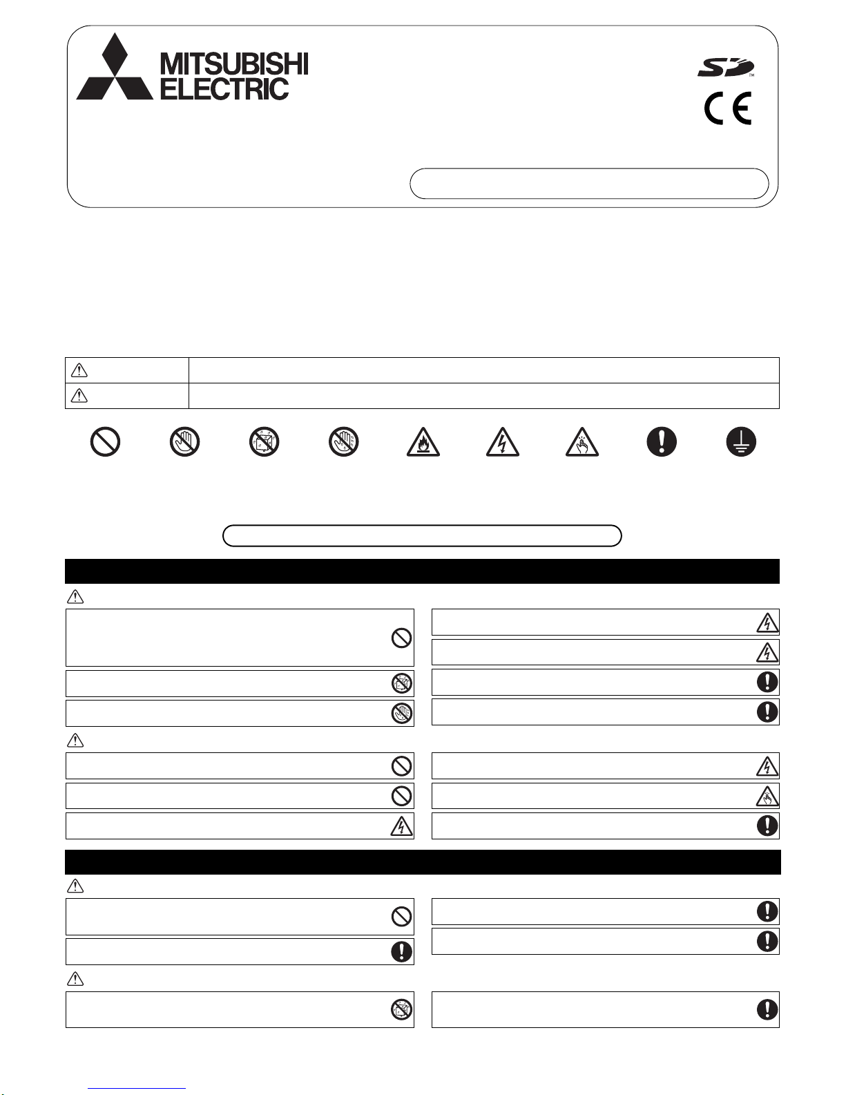
(Prohibited actions) (Do not touch) (No water) (No wet hands) (Fire hazards) (Electric shock hazards) (Injury hazards) (Important actions) (Grounding required)
General precautions
Precautions during installation
Air-conditioner Control System
Advanced Touch Controller AT-50A
Installation Manual For distribution to dealers and contractors
WT06091X01
All electric work must be performed by qualified personnel.
Do not install the unit in a place where large amounts of oil, steam, organic
solvents, or corrosive gases, such as sulfuric gas, are present or where acidic/
alkaline solutions or sprays are used frequently. These substances can
compromise the performance of the unit or cause certain components of the
unit to corrode, which can result in electric shock, malfunctions, smoke, or fire.
To reduce the risk of shorting, current leakage, electric shock, malfunctions,
smoke, or fire, do not wash the controller with water or any other liquid.
To reduce the risk of electric shock, malfunctions, smoke or fire, do not operate
the switches/buttons or touch other electrical parts with wet hands.
T o reduce the risk of injury or electric sho ck, before sprayin g a chemical around
the controller, stop the operation and cover the controller.
To reduce the risk of injury or electric shock, stop the operation and switch off
the power supply before cleaning, maintaining, or inspecting the controller.
Properly install all required covers to keep moisture and dust out of the controller.
Dust accumulation and water can cause electric shock, smoke, or fire.
To reduce the risk of injury, keep children away while installing, inspecting, or
repairing the controller.
To reduce the risk of fire or explosion, do not place flammable materials or use
flammable sprays around the controller.
To reduce the risk of damage to the controller, do not directly spray insecticide
or other flammable sprays on the controller.
To reduce the risk of electric shock or malfunctions, do not touch the touch
panel, switches, or buttons with a pointy or sharp object.
To reduce the risk of injury and electric shock, avoid contact with sharp edges
of certain parts.
To avoid injury from broken glass, do not apply excessive force on the glass
parts.
To reduce the risk of injury, wear protective gear when working on the
controller.
Do not install the controller where there is a risk of leaking flammable gas.
If flammable gas accumulates around the controller, it may ignite and cause a
fire or explosion.
Properly dispose of the packing materials. Plastic bags pose suffocation hazard
to children.
Take appropriate safety measures against earthquakes to prevent the
controller from causing injury.
To prevent injury, install the controller on a flat surface strong enough to
support its weight.
To reduce the risk of shorting, current leakage, electric shock, malfunctions,
smoke, or fire, do not install the controller in a place exposed to water or in a
condensing environment.
Controller must be installed by qualified personnel according to the instructions
detailed in the Installation Manual.
Improper installation may result in electric shock or fire.
Page 2
– 2 –
WARNING
CAUTION
WARNING CAUTION
1-2. The CD-ROM that is supplied with AT-50A
The CD-ROM that is supplied with AT-50A has Installation Manual and Instruction Book in English, German, French, Spanish, Italian,
Portuguese, and Russian.
Each document is in PDF format.
Viewing documents requires a computer with Adobe Reader or Adobe Acrobat installed.
“Adobe Reader” and “Adobe Acrobat” are registered trademarks of Adobe Systems Incorporated.
Precautions during wiring
Precautions for moving or repairing the controller
Additional precautions
WARNING
The CD-ROM that is supplied with the Remote Controller can only be played on a CD-drive or a DVD-drive.
Do not attempt to play this CD-ROM on an audio CD player as this may damage your ears and/or speakers.
To reduce the risk of damage to the controller, malfunctions, smoke, or fire, do
not connect the power cable to the signal terminal block.
Properly secure the cables in place and provide adequate slack in the cables
so as not to stress the terminals. Improperly connected cables may break,
overheat, and cause smoke or fire.
To reduce the risk of injury or electric shock, switch off the main power before
performing electrical work.
All electric work must be performed by a qualified electrician according to the
local regulations, standards, and the instructions detailed in the Installation
Manual. Capacity shortage to the power supply circuit or improper installation
may result in malfunction, electric shock, smoke, or fire.
To reduce the risk of electric shock, install a breaker and a residual current
circuit breaker on the power supply . To reduce the risk of electric shock, smoke,
or fire, install a breaker for each controller.
Use properly rated breakers and fuses (breaker, local switch <switch + fuse>,
no-fuse breaker). The use of a breaker with a breakin g capacity grea te r than th e
specified capacity may cause electric shock, malfunctions, smoke, or fire.
To reduce the risk of current leakage, overheating, smoke, or fire, use properly
rated cables with adequate current carrying capacity.
Proper grounding must be provided by a licensed electrician.
Do not connect the grounding wire to a gas pipe, water pipe, lightning rod, or
telephone wire. Improper grounding may result in electric shock, smoke, fire, or
malfunction due to electrical noise interference.
To reduce the risk of electric shock, shorting, or malfunctions, keep wire pieces
and sheath shavings out of the terminal block.
To reduce the risk of shorting, current leakage, electric shock, or malfunctions,
keep the cables out of contact with controller edges.
To reduce the risk of electric shock, malfunctions, or fire, seal the gap between
the cables and cable access holes with putty.
The controller should be repaired or moved only by qualified personnel. Do not
disassemble or modify the controller.
Improper installation or repair may cause injury, electric shock, or fire.
To reduce the risk of shorting, electric shock, fire, or malfunction, do not touch
the circuit board with tools or with your hands, and do not allow dust to
accumulate on the circuit board.
To avoid damage to the controller, use appropriate tools to install, inspect, or repair
the controller.
AT-50A is designed for exclusive use with the Building Management System by
Mitsubishi Electric. The use of this controller for with other systems or for other
purposes may cause malfunctions.
Take appropriate measures against electrical noise interference when installing the
air conditioners in hospitals or facilities with radio communication capabilities.
Inverter, high-frequency medical, or wireless communication equipment as well as
power generators may cause the air conditioning system to malfunction. Air
conditioning system may also adversely affect the operation of these types of
equipment by creating electrical noise.
To avoid malfunctions, do not bundle power cables and signal cables together, or
place them in the same metallic conduit.
To avoid damage to the controller, do not overtighten the screws.
To avoid discoloration, do not use benzene, thinner, or chemical rag to clean the
controller. To clean the controlle r, wipe with a soft cloth soaked in water with mild
detergent, wipe off the detergent with a wet cloth, and wipe off water with a dry cloth.
To avoid damage to the controller, provide protection against static electricity.
Do not use solderless terminals to connect cables to the terminal block.
Solderless terminals may come in contact with the circuit board and cause
malfunctions or damage the controller cover.
To avoid damage to the controller, do not make holes on the controller cover .
To avoid deformation and malfunction, do not install the remote controller in direct
sunlight or where the ambient temperature may exceed 40ºC (104ºF) or drop below
0ºC (32ºF).
Page 3
– 3 –
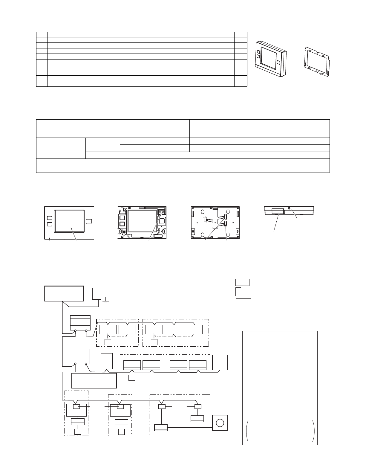
1-3. Parts list
The package contains the following parts.
1-4. Product specifications
1. Specifications
*1 Not for use with a generic DC power supply device. Use the power supply unit for transmission line (PAC-SC51KUA etc.) by Mitsubishi.
*2 "Power consumption Coefficient" is a coefficient to calculate the relative power consumption of the devices that receive power through the M-NET
transmission line. Refer to the note at the end of section 1-5 "System diagram."
2. Unit Components and Functions
1-5. System diagram
1. System configuration
*1 ISO metric screw thread
Power source
30VDC *1
(for connection to M-NET only)
Receives power from the power supply unit for transmission line or
from outdoor units via the M-NET transmission cable. The power
consumption coefficient*2 of AT-50A is "4."
Operating conditions
Temperature
Operating temperature range 0˚C~40˚C [32˚F~104˚F]
Storage temperature range -20˚C~+70˚C [-4˚F~+158˚F]
Humidity 30%~90%RH (Non-condensing)
Weight 0.5 kg [1-1/8 lbs.]
External dimensions (W x H x D) 180 x 120 x 30 mm 7-3/32 x 4-23/32 x 1-3/16 in
Front (with the cover on) Front (cover off) Back Bottom
Parts Qty.
1. AT-50A 1
2. Mounting bracket 1
3. M4.1 wood screws × 16 *1 (Use to attach the mounting bracket to a wall.) 4
4. M4 Roundhead cross slot screws × 30 *1 (Use to attach the mounting bracket to an electric box.) 2
5. M4 roundhead screws with spring washers/washers × 20
(Use to attach the mounting bracket to th e controller.) *1
2
6. Installation Manual (This manual) 1
7. Instruction Book 1
8. CD-ROM (Instruction Book, Installation Manual) 1
2. Mounting bracket1. AT-50A
Power LED Touch panel
For connection to the M-NET
(A, B: Terminal for connection to
the M-NET cable [non-polarized])
External output
adapter cable
access hole
External input
adapter cable
access hole
Controller cover
mounting screw
SD memory slot
(for program updates)
TB7 TB3
ME
MA
MA
R2
TB7 TB3
MA MA
[051]
[001]
[106]
[006] [007] [008] [009]
[010]
[056]
[057]
[002] [003] [004] [005]
[11]
[12]
[13] [14]
M-NET
Main SC
Advanced Touch
Controller
*1
Model:
AT-50A [201]
Power supply unit for transmission cable
(sold separately)
Model: PAC-SC51KUA
Outdoor unit
M-NET
Group 1
M-NET
Outdoor unit
Group 2
Indoor unit
Local remote controller
M-NET transmission cable
MA remote controller c a b le
Numbers in the parentheses indicate address
numbers.
Note:
• The figure at left only shows the
transmission line connections.
Power supply lines are omitted.
• Provide a single ground point
(class D) by grounding the shield
wire of the M-NET centralized
controller transmission cable at
one of the power supply units.
Provide a ground point for the
indoor-outdoor transmission
cable for each outdoor unit.
• Make sure that the centralized
control switch (SW2-1) on the
outdoor unit connected to the MNET cable is set to ON.
Refer to the outdoor unit
Installation Manual for detailed
information about dip switch
settings.
BC controller
Group 3
Group 6
Group 4 Group 5
M-NET
adapter
LOSSNAY
unit
Outdoor
unit
ON/OFF remote controller
Model: PAC-YT40ANR A
[202]
Mr. Slim
®
outdoor unit
Mr. Slim
®
outdoor unit
M-NET
Interface
MXZ
Page 4

– 4 –
*1 The power consumption coefficient of AT-50A is 4 and that of an indoor unit is "1"*, which means that each AT -50A unit consumes power equivalent to
four indoor units. (*Indoor units receive power through the M-NET transmission line to maintain communication during power failure.) Refer to the
CITY MULTI DATABOOK for details. The total power consumption of the connected devices should not exceed the capacity of the power supply units.
The Design Tool by MITSUBISHI ELECTRIC allows its user to design air conditioning systems easily.
AT-50A is compatible with the Design Tool version 3.9 or later.
AT-50A can be connected to either TB7 or TB3.
When connected to TB3, no power supply units are required.
• Address settings (Address overlaps are not allowed.)
Note
2. M-NET wiring design
(1) M-NET transmission cable specifications and restrictions
Address setting Address range
Indoor unit
Assign the lowest address to the main indoor unit in the group, and assign sequential addresses to
the rest of the indoor units in the same group.
Note: The following models require two addresses: PEFY-AF1200CFM and PEFY-AF1200CFM-R
1~50
Outdoor unit
Assign an address that equals the lowest indoor unit address in the same refrigerant system plus
50.
51~100
Auxiliary outdoor unit
(BC controller)
Assign an address that equals the address of the outdoor unit in the same refrigerant system
plus 1.
52~100
LOSSNAY unit
Assign an arbitrary but unused address to each LOSSNAY unit after assigning an address to all
indoor units.
1~50
Mr. Slim
®
unit Same rules as for the indoor units apply. An M-NET adapter (sold separately) is required. 1~50
MXZ unit Same rules as for the indoor units apply. An M-NET interface (sold separately) is required. 1~50
M-NET remote controller
Assign an address that equals the address of the main indoor unit with the lowest address in the
group plus 100. Add 150 instead of 100 to set a sub-remote controller.
101~200
Sub system controller Assign an address that equals the lowest number of the group to be controlled plus 200. 201~250
DIDO
(PAC-YG66DCA)
Assign an arbitrary but unused address to the controller after completing the address setting for
the units with an address between 1 and 50. The number of controllable units depends on the
number of channels used. (1 channel = 1 unit)
1~50
MA remote controller
Address setting is not required. The connection of two remote controllers requires the main/sub
setting for each controller to be made.
–
Cable
Specifications
Facility type All facility types
Type
Shielded cable
CVVS · CPEVS · MVVS
No. of cores 2-core
Size
CVVS, MVVS: 1.25 mm² (AWG16) or larger
CPEVS: ø1.2 mm (AWG16 or its equivalent) or larger
Maximum indoor-outdoor transmission cable length 200 m [656 ft]
Maximum length of transmission line for centralized control and
indoor-outdoor transmission cables
(Maximum cable distance via outdoor unit)
500 m [1640 ft]
*The maximum cable distance from the power supply unit to each outdoor
unit or to the system controller is 200 m [656 ft].
• The system cannot be configured as shown in the examples below.
►Groups that are not controlled by a main controller cannot be
controlled from a sub controller.
►Sub controllers cannot be controlled by two or more main controllers.
►Each group cannot be controlled by two or more main
controllers.
Group Group Group Group Group Group
Group
Group Group Group
Main system controller 2Main system controller 1
Main system controller Sub system controller
Sub system controller
Main system controller 1 Main system controller 2
Page 5
– 5 –
The figure below shows the M-NET transmission wiring diagram for City Multi air conditioners.
The maximum length of centralized control M-NET transmission line and the indoor-outdoor transmission line per system can be expressed in
the following formulas. Labels "a through g" represent the sections of wiring in the system in the figure below. These limits ensure normal signal
communication over the M-NET transmission line.
If the line length exceeds the maximum length, M-NET signal attenuation can occur, rendering normal communication and control impossible.
a+b+d+e(f) ≤500 m (1640 ft) a+b+c+g ≤500 m (1640 ft) e(f)+d+c+g ≤500 m (1640 ft)
The maximum length of local remote controller cable is 10 m (32 ft). The length that exceeds 10 m (32 ft) must be included in the maximum total
line length 500 m (1640 ft).
1-6. Installation
1. Field-supplied parts
The following parts are required to install the controller.
2. Required tools
• A knife or nippers • Crosshead driver
3. Installation methods
Follow the instructions provided for the selected installation option.
(a) Wall-embedded installation using an electric box
(b) Wall-surface installation
(b-1) To route the cable through the wall
(b-2) To route the cable along the wall surface
4. Preparation
(1) Install a breaker on the power supply unit side before installing the controller.
(2) Select an installation site for the AT-50A.
• Install the controller at the user's eye level for easy operation.
• Ensure there is enough clearance space as shown in the figure at right.
• Ensure there is enough clearance space to allow for easy access to the panel and the
buttons.
(3) Bring the cable end up to the controller.
Ensure the M-NET transmission cables and external input/output cables are long enough to reach
the controller. Have extra cables to extend these cables as necessary.
• To install the controller according to the instructions provided in sections (a) and (b-1) above
Include an extra 30 cm (12 in) of cable to provide adequate slack in the cable.
Remove the sheath on the M-NET transmission cable up to 20 cm (8 in) from the end.
• To install the controller according to the instructions provided in section (b-2) above
Include an extra 15 cm (6 in) of cable to provide adequate slack in the cable.
Remove the sheath on the M-NET transmission cable up to 10 cm (4 in) from the end.
(4) Prepare the AT-50A.
Unscrew the screw at the bottom of the controller, and
remove the cover.
To route the cable along the wall surface, cut out the
rectangle knockout hole (18 mm (W) x 9 mm (D)) at
the top of the controller with a knife or a nipper (shown
as the shaded area in the figure below at right).
Parts Qty. Note
Triple electric box 1
Not required for wall-surface installationThin metal conduit As appropriate
Lock nut and bushing As appropriate
M-NET cable As appropriate
Shielded cable
CVVS, MVVS: 1.25 mm²~2 mm² (AWG16~14)
CPEVS: ø1.2 mm~ø1.6 mm (AWG16~14 or their equivalents)
a
c
edb
f
g
Power supply
unit for transmission
cable
Outdoor
unit
Indoor unit Indoor unit
Indoor unit
Indoor unitIndoor unit
Outdoor
unit
System
controller
Centralized controller
transmission line
M-NET
remote
controller
10 m (32 ft)
Indoor-outdoor
transmission line
30
(1.3/16)
30 (1.3/16)
50 (2)
30
(1.3/16)
Unit: mm (in)
AT-50A outline
Note
Note
Refer to section 1-7 "Using external
input/output" for how to connect
external input/output signal cables.
Do not push the shield wire into or
connect it to the AT-50A. Trim the
shield wire, cover it with vinyl
insulating tape, and leave it
outside the controller.
Page 6

– 6 –
5. Installation steps
(1) Routing the cables
(a) Wall-embedded installation using an electric box
Pull the M-NET transmission cable through the hole on the wall and the electric box, and seal
the gap between the cable and the end of the conduit tube.
(b) Wall-surface installation
• To route the cable through the wall:
Drill a hole in the wall, push the M-NET transmission cable through the hole, and seal the
gap between the cable and the hole with putty.
• To route the cable along the wall surface:
It is approximately 10 cm (4 in) from the cable access hole on the back of AT-50A to the
M-NET terminal block. Trim off the excess transmission cable, if any.
(2) Attach the mounting bracket on the wall.
Attach the mounting bracket on the designated area on the wall using the supplied screws.
The pitch for the mounting bracket is shown in the figure at right.
(3) Attach the controller to the mounting bracket.
After inserting the M-NET transmission cables (A and B) through the cable access hole on the
controller from the back, hang the controller on the hooks of the mounting bracket.
Attach the controller to the mounting bracket using twenty M4 screws with spring washers/
washers.
(4) Connect the cables.
Connect the M-NET transmission cables (A and B) to the terminal block. M-NET transmission
cable is non-polarized.
Insert the cables in the groove on the controller so they will not be pinched when the cover is
installed.
*To route the cable along the wall surface
Secure the cables in place with a cable cover, and seal the gap between the cable cover and the
controller with putty.
(5) Replace the cover.
Snap the cover into place, and attach it to the controller with a screw at the bottom.
*Tighten the screw to a torque of 10 N·m or less.
Remove the sheath,
and insulate the
shield wire with
vinyl tape.
Seal the gap with putty.
M-NET transmission cable
A, B
Remove the sheath,
and insulate the
shield wire with vinyl tape.
Wall
Wall
M-NET transmission cable
A, B
Electric box
Seal the gap with putty.
Bushing
Cable access hole
Locknut
Conduit tube
To reduce the risk of electric shock, malfunctions, or fire, seal the
gap between the cables and access holes with putty .
A B
92 (3.5/8)
83.5 (3.5/16)
Cable access hole
Insert the cable into the groove.
M-NET transmission cable
(non-polarized)
Screw the controller
on the bracket.
Hang the controller on the
hooks of the mounting bracket.
Unit: mm (in)
Note
• The M-NET terminal on the controller is only for connection to the M-NET cable.
Do not connect an AC power supply.
• Do not daisy-chain M-NET terminals.
Use a cable cover.
Seal the gap with putty.
To reduce the risk of electric shock, malfunctions, or fire, seal the
gap between the cables and access holes with putty.
Page 7

– 7 –
1-7. Using external input/output
1. External signal input (CN2)
*To use external input, an external input/output adapter (PAC-YT41HAA; sold separately) is required.
(1) External input
Using external dry contact signals, the following operation of all air conditioning units can be controlled from the AT-50A: Emergency stop/Normal
operation, ON/OFF , Permit/Prohibit local remote controller operation. These settings are made on the External Input Settings on the Initial Settings
screen that is accessible from the Service Menu screen. (Refer to section 2-3.)
(2) Level signal and pulse signal
(A) Level signal (B) Pulse signal
(3) External input specifications
(A) Level signal
• If the type of signal assigned to the external input contact is "Emergency/Normal," the units in normal operation will stop when the signal
input changes from OFF to ON. Conversely, the units that are stopped will resume normal operation when the signal changes from ON to
OFF. After the emergency stop is reset, the original operating status of each air conditioning unit will not be automatically restored. The air
conditioning units must be started up manually.
• If the type of signal assigned to the external input contact is "ON/OFF," the units that are stopped will start operation after the input signal
changes from OFF to ON. Conversely, the units that are in operation will stop after the input signal changes from ON to OFF.
(B) Pulse signal
• If the incoming signal is the same as the signal that is currently being received, no status change will occur.
• If local remote controller operation is prohibited, ON/OFF status, operation mode, or temperature setting cannot be changed and filter sign
cannot be reset from the remote controller.
• The ON-signal pulse width should be set to a value between 0.2 and 1 seconds.
(4) Sample circuit recommended
Mode External input signal setting Notes
1 Do not use external input. (Factory setting) –
2
Emergency stop/Normal operation signal (level
signal)
When the units are not operating after receiving an emergency stop signal, the ON/
OFF operation from the local remote controller will not be allowed, and the ON/OFF
and Prohibit/Permit settings on the AT-50A cannot be changed. Timer operation will
not function.
3 ON/OFF signal (level signal)
ON/OFF operation from the local remote controller will not be allowed, and the ON/
OFF and Prohibit/Permit settings on the AT-50A cannot be changed. Timer
operation will not function.
4
ON/OFF and Prohibit/Permit remote controller
operation signal (pulse signal)
The ON-signal pulse width should be set to a value between 0.2 and 1 seconds.
CN2 Lead wire
Emergency stop/Normal
operation signal (level signal)
ON/OFF level signal
ON/OFF, Prohibit/Permit remote
controller operation (pulse signal)
1 Green Built-in 5 VDC power for external input * Exclusively for use with external input. Not usable for other purposes.
2Yellow
Emergency stop/Normal operation
signal input
ON/OFF signal input ON signal input
3 Orange Not used Not used OFF signal input
4 Red Not used Not used
Prohibit-local-remote-controlleroperation signal input
5 Brown Not used Not used
Permit-local-remote-controlleroperation signal input
(A) Level signal (B) Pulse signal
*Same for Prohibit/Permit remote controller operation.
Contact ON
Contact OFF
Contact ON
Contact OFF
Contact ON
Contact OFF
Contact ON
Contact OFF
ON
OFF OFF
ON
OFF
OFF
(ex.)ON/OFF
Signal 1 (ON)
Signal 2 (OFF)
0.2 to 1 seconds
0.2 to 1 seconds
Normal
operation
Normal
operation
Emergency
stop
CN2
X1
AT-50A
X1
1
2
3
4
5
Maximum
10 m
(32 ft)
Field supplied
Yellow
Green
ON/OFF
or Emergency stop
X1
X2
Y1
Y2
CN2
X1
AT-50A
X2
Y1
Y2
1
2
3
4
5
Orange
Maximum
10 m
(32 ft)
Field supplied
Brown
Red
Yellow
Green
ProhibitON
PermitOFF
Page 8

– 8 –
• The relays and extension cables are field supplied.
• Use a no-voltage contact and minute load relay (minimum application load 5VDC-1mA).
• The length of the connection cable extension should not exceed 10 m (32 ft). (Use a cable of 0.3 mm² (22AWG) or thicker.)
• Insulate the area with vinyl tape where the controller cable and the extension cable are connected.
• Insulate the end of unused lead wires with tape.
2. External signal output
*To use external output, an external input/output adapter (PAC-YT41HAA; sold separately) is required.
Requires a separate external power source.
(1) External signal output (CN3)
Operation signal will be output when one or more air conditioning units are in operation, and error signal will be output when one or more units are
in error.
The On-signal will be output even during an error.
(2) External output specifications
(3) Sample circuit recommended
1-8. Using an SD memory card
1-9. Optional Parts
1-10. Note
A protective film is placed on the display.
Remove the protective film off the display before use.
CN3 Lead wire Signal CN3 Lead wire Signal
1 Brown ON/OFF 3 Orange Ground for all external outputs
2 Red Error/Normal 4 Yellow Not used
Relay-driven circuit Use relays that meet the following specifications for relays indicated as Z1 and Z2 in
the figure.
Operating coil
Rated voltage: 12 VDC or 24 VDC
Power consumption: 0.9 W or below
(*1) Select a power supply suitable for the relays used. (12 VDC or 24 VDC)
(*2) Use a diode at each end of the relay coil.
• Each element will turn on when an error occurs during operation.
• The maximum length of extension cable is 10 m (32 ft). (Use a cable of 0.3 mm²
(22AWG) or thicker.)
• Insulate the area with vinyl tape where the controller cable and the extension
cable are connected.
• Relays, lamps, diode, extension cables are field-supplied.
Note
The AT-50A has a slot for an SD memory card at the bottom that
can be used to update software.
Refer to the Installation Manual for the detailed information about
updates.
*Only the 1GB and 2GB SD memory cards by SanDisk are
supported.
Parts Model Usage Note
External input/output
adapter
PAC-YT41HAA Enables the use of external
input/output function
Required to use the external input/output function
5-wire cable (input) , 4-wire cable (output)
CN3
Z2 L2
L1
AT-50A
2
1
3
4
Z2
Z1 Z1
Brown
Red
Orange
Maximum
10 m
(32 ft)
Power source
(*1)
Diode (*2)
L1 : Operation indicator
L2 : Error indicator
Field supplied
Yellow
• To connect cables from an external input/output adapter to connectors CN2 and CN3 on the controller, cut out the appropriate knockout
holes on the controller with nippers.
After connecting the cables to the connectors, hold the cables in place with a piece of tape included with the external input/output
adapter (PAC-YT41HAA).
• Use caution not to damage the circuit board with the nippers or other tools when cutting out knockout holes.
Back of controller
CN2
External input connector
Tape
External
input/output adapter
CN3
External output connector
Cut out the
knockout holes.
“SD Logo is a trademark of SD-3C, LLC.”
(a)
(b)
(c)
(a) Remove the SD memory card slot cover from the controller.
(b) Insert the SD memory card into the slot until it clicks.
(c) To remove the SD memory card, push it in until it clicks.
Bottom of controller
SD memory slot (for program updates)
Page 9

– 9 –
Chapter 2. Initial Setting
This chapter contains information about the settings to be made at the time of installation. Please read the instructions carefully and make
the settings accordingly. Refer to Chapter 1. “Installation” for how to install the AT-50A Advanced Touch Controller, and refer to the air
conditioning unit installation manuals for how to connect the controller cable to the air conditioning units, or how to install the air conditioning
units. Please remember to give all manuals to the end users after installation is complete.
2-1. AT-50A Advanced Touch Controller
List of functions available under the “Service menu”
(*1) Refer to section 1-5 “Note.”
(*2) Available only when AT-50A is set as a main controller.
Screen Setting Function Page
Basic
settings
M-NET address Sets the M-NET address for the AT-50A. 12
Main system controller/
sub system controller (*1)
Set the system controller as the main or sub.
12
Operation prohibit setting
(Used/Not used)
Use to select the type of controller from which to prohibit the access of the local
remote controllers (from other system controllers).
12
Remote controller access
Selects the type of controllers to prohibit access* from (remote controllers only or
both remote controllers and system controllers).
* Access to ON/OFF, Mode, Set Temp, and Filter Reset.
12
External input mode Selects the external input mode. 12
Filter sign Displays or suppresses the Filter sign on the HOME screen. 12
Dry mode Includes or excludes Dry mode as an option for the operation mode. 12
Set temperature range
(Schedule)
Selects the settable temperature range:
Standard: 19°C (67°F) to 28°C (83°F); Low: 8°C (46°F) to 30°C (87°F );
Manual: Settable to any arbitrary range between 8°C (46°F) and 30°C (87°F).
12
Time notification
Sends or does not send the clock synchronization signal once a day to the
controllers and units.
13
Operation mode control
(*2)
Selects the function “System-Chang e ove r” or “Ope ra ti o n Mo de Sel e cti o n Li mit”.
13
Group
settings
Groups
Makes the group settings for the indoor units, LOSSNAY units, DIDO controllers
(PAC-YG66DCA), remote controllers, and sub-system controllers.
13
Interlocked operation Enters the interlock settings between indoor and LOSSNAY units. 14
Batch deletion (*2) Deletes all group and interlock settings collectively. 14
Maintenance
System view Displays the information about the indoor units connected to each outdoor unit. 15
Malfunction log Stores the latest errors. (up to 50) 15
Checking the Gas Amount
(*2)
Use to check for refrigerant leak from the outdoor unit.
15
Software update Updates software. 16
Test run Test run Runs a test on the connected air conditioning units. 15
Function 1 button with LED
Function 2 button with LED
Power LED
Collective ON/OFF
button with LED
Touch panel
Page 10

– 10 –
2-2. AT-50A Screen Configurations
(1) Screen sequence and Service menu configuration.
*1 A password is required to access the Service menu.
• The initial Service password is “9999.” Change the password as necessary to prevent unauthorized access.
• Make sure the password is available to the maintenance and other necessary personnel.
• The password can be set to an arbitrary number between four and eight digits.
• If you forget your password, log in with the master password.
Master password: 105638
• The same master password is used to log in to specific screens under the “Main Menu” and the “Service Menu.”
Touch [ ] or [ ].
HOME screen
GRID (zoom-out) view GRID (zoom-in) view
LIST view GROUP view
Main Menu screen
Login Page screen *1
Password Change screen
Service Menu
Service Menu screen
Initial settings 1/
Basic system
Initial settings 2/
Groups
Groups
Interlocked LOSSNAY
Delete All
System view
Malfunction log
Gas Amount Check
Maintenance
Test run
Software update
Button name
Main Menu
Service Menu
Password Change
Back
HOME
Cancel
Login
OK
Initial Settings 1/Basic system
Initial Settings 2/Groups
Maintenance
Test run
Groups
Interlocked LOSSNAY
Delete All
System view
Malfunction Log
Gas Amount Check
Software Update
Icon
Touch [ ].
Touch [ ]. Touch [ ].
Touch [ ].
Touch [ ].
Touch [ ].
*Touch [ ] on each screen to return to a previous screen.
Touch [ ].
Touch [ ].
Touch [ ].
Touch [ ].
Touch [ ].
Touch [ ].
Touch [ ].
Touch [ ].
Touch [ ].
Touch [ ].
Touch [ ].
Touch [ ].
Touch [ ].
Touch [ ].
Page 11

– 11 –
2-3. Initial Settings
(1)Initial startup settings:
Before turning on the controller, first make sure that the controller, indoor units, and outdoor units have been installed properly according
to the instructions detailed in the respective manuals.
Turn on the controller and the units.
• This manual is intended for the first startup after the unit has been shipped from the factory. If the setting has been changed even
once, the popup window or setting screens explained below may not appear. In this case, see section “Usage-Main Menu Setting” in
the Instruction Book.
• AT-50A can be used as a Main controller or a Sub controller. At the time of factory shipment, AT-50A is set as a Main controller. The
Main/Sub setting can be changed on the Initial Settings 1/ Basic System screen from the Service menu. (Refer to section 2-3(2)-1 for
details.)
• Change the Main/Sub setting BEFORE making other initial settings, otherwise some saved information will be lost upon restart after
the setting is changed.
<When a popup message “Make a setting from Initial Settings
1.” appears>
(c) Press the OK button to close the popup window and display the
Service Menu screen.
(d) Touch the Initial Settings 1/ Basic System button to make a
setting. (Refer to section 2-3(2)-1 for details about Basic
controller settings.)
Save the settings, and go back to the Service Menu.
(e) Touch the Initial Settings 2/ Groups button to make a setting.
(Refer to section 2-3(2)-2 for details about Group settings,
2-3(2)-3 for details about Interlocked settings.)
Save the settings, and go back to the Service Menu.
(f) Touch HOME button [ ] to bring up a popup confirmation
screen.
Press the OK button to begin the communication.
(g) The message (shown above) will appear on the screen,
displaying the initialization progress. When initialization is
complete, the screen will automatically return to the HOME
screen.
(Initialization will take up to five minutes.)
* To change settings later, perform a test run, or verify the
maintenance information.
1 Touch MAIN MENU button [ ] on the HOME screen.
2 Touch SERVICE MENU button [ ] on the Main Menu
screen.
3 Enter the password to log on to the Service Menu screen.
(Refer to section 2-3, 2-4, and 2-5.)
<When a popup message “Make a group setting using the
Main controller. When the group setting has been made, reset
the power to the Main controller.” appears>
(c) While the popup message is displayed, the unit communicates
with the main controller. The popup window will close when the
communication is completed.
* To change the settings, press the Cancel button while the
popup window is displayed. The Initial Settings 1/ Basic
System screen will appear. If Basic controller settings are not
made yet, change the settings.
(d) The message (shown above) will appear on the screen,
displaying the initialization progress. When initialization is
complete, the screen will automatically return to the HOME
screen.
(Initialization will take up to ten minutes.)
* The group name needs to be set on the Sub controller after
normal startup, as it cannot be sent from the Main controller.
Refer to the Instruction Book for details.
(a) The Language screen will appear.
1 Select the display language.
2 Touch the button to select the
language of your choice.
3 Touch the OK button.
(b) The Date and Time screen will appear.
1 Set the current date on the Date tab, and set the current time on the Time t ab,
using the ▼ and ▲ buttons to change the values.
2 Click on the checkbox next to the date/time format of your choice.
3 Touch the Save button to save the settings.
Page 12

– 12 –
(2) Other Initial Settings
(2)-1. Basic controller setting
Touch Initial Settings 1/Basic System button [ ] on the Service menu screen to access
the Initial Settings 1/Basic System screen.
Touch Page tu rn button [ ][ ] to turn the pages, and follow the directions below to
make the settings.
M-NET Address
1) Touch the M-NET Address button (labeled 1 in the figure), and set the AT-50A
Controller address on the screen that pops up.
• The address can be set to 000 or to a value between 201 and 250 (the factory
setting is 201).
Main or sub controller setting (when connecting both main and sub controllers)
1) Touch the button marked 2 in the figure to set MAIN or SUB for the controller.
• The factory setting is MAIN.
Operation prohibit setting
1) Touch the button marked 3 in the figure to use or not use the Operation prohibit setting.
• To prohibit the access of the local remote controller from AT-50A, select “Enabled.” If this setting is set to “Enabled,” a button will
appear in the place marked 4 in the figure.
Remote Controller Access
1) Touch the Remote Controller Access setting button (labeled 4 in the figure) to switch between “SC/RC” and “RC only.”
• Select “SC/RC” to prohibit access* from both the system controllers and remote controllers, and select “RC only” to prohibit
access from only the remote controllers.
* Access to ON/OFF, Mode, Set Temp , and Filter Reset.
External Input Mode
1) Press the External Input setting button (labeled 1 in the figure) to select between “Not
used,” “Emergency Stop (Level signal),” “ON/OFF (Level signal),” and “ON/OFF/
Prohibit/Permit (Pulse signal).”
* Refe r to the Installation Manual for detailed information on how to connect the
AT-50A to external devices.
Filter Sign Display
1) Press the Filter Sign Display button (labeled 1 in the figure) to switch between ON
and OFF.
• Setting this item to OFF will remove the Filter Sign from the HOME screen display.
This item can be set to OFF if there is no need for the sign to appear on the HOME
screen; for example, in cases where filters are regularly changed regardless of the
filter sign status.
Dry Mode
1) Press the Dry Mode Setting button (labeled 2 in the figure) to switch between "Used"
and “Not Used.”
• If this item is set to “Not Used,” the Dry mode will be unavailable for selection.
Set Temperature Range (Schedule)
Set the temperature range that is available from the Set Schedule screen.
1) Touch the Set Temp erature Range button (labeled 1 in the figure) to switch
between Standard, Low, and Manual.
The temperature set range for each option is shown below:
Standard : 19ºC (67ºF) to 28ºC (83ºF)
Low : 8ºC (46ºF) to 30ºC (87ºF)
Manual : Can be set to any arbitrary range between 8ºC (46ºF) and
30ºC (87ºF)
2) When “Manual” is selected, set the lower and upper temperature limits using the
up and down arrows (labeled 2 in the figure).
1
4
2
3
Page turn button
Page No./No. of pages
1
1
2
1
2
Page 13

– 13 –
Clock Setting Signal
1) T ouch the Clock Setting Signal button (labeled 1 in the figure) to send or not send the
clock synchronization signals to other controllers and units.
• If the Clock Setting Signal is set to “ON,” signals to synchronize the current time will
periodically be sent to all system controllers and remote controllers that have a builtin clock function.
* MA remote controllers that are connected to Mr. SLIM
®
units will not synchronize the
clock and date. Also, the clock and date synchronization may not operate on certain
CITY MULTI units.
Operation Mode Control (Available only when AT-50A is set as a main controller)
1) Touch the button marked 2 in the figure to switch the following functions.
System-Changeover: Based on the room temperature and the preset temperature, the operation mode (cooling or heating) is
automatically switched for the whole system.
Operation Mode Selection Limit: The specific operation mode’s changeover is restricted for this remote controller and other
local remote controllers of all groups.
Saving the Settings
1) Touch the Save button to save the settings.
(2)-2. Group Settings
This setting can be made only when AT-50A is set as a main controller. If AT-50A is set as a sub controller, the setting can be monitored
only.
Enter the group settings on the Groups screen (air conditioning units, general equipment (and their respective group names) that are
connected to AT-50A). Touch Initial Settings 2/Groups button [ ] on the Service Menu screen, and then touch Groups button [ ]
on the Initial Settings 2/Groups screen to access the Groups screen. The DIDO controller (PAC-YG66DCA) by Mitsubishi Electric is
required to control general equipments.
* General equip ments: Refer to the types of equipments such as fans and lighting fixtures that are connected to the contacts.
Each contact of general equipment counts as one unit, and up to 50 units (indoor units and LOSSNAY units combined) or their
equivalent can be connected to each AT -50A.
Up to 16 units can be assigned to each group. Indoor units, LOSSNAY unit s, and general equipment cannot be combined in one group.
General equipment groups cannot include remote controller or system controllers. Touch Page turn button [ ][ ] to turn the
pages, and follow the directions below to make the settings for each group.
Group Name
1) T ouch the Group Name Input button (labeled 1 in the figure), and enter the group
name in the screen. (up to 16 characters maximum)
2) The name of a group can be copied and pasted into another group name field.
Access the name of the group to be copied using the arrow buttons, and touch
the Copy button [ ].
Access the page to paste the copied group name onto, and touch the Paste
button [ ].
Group Settings for air conditioning units
1) Touch the Model selection button (labeled 2 in the figure) to access the Model
Selection screen. Touch the Model selection button (labeled 6 in the figure) so
that “Air Conditioners” or “LOSSNAY” appears on the screen.
2) Touch the Unit selection button (labeled 3 in the figure). On the popup window
that appears, check the address of the units to be included.
3) To assign a remote controller to a group, check the address of controller on the
popup window that appears when the Remote controller selection button (labeled
4 in the figure) is touched.
* Up to two remote controllers can be assigned to each group. (Group settings do
not need to be made for the MA remote controllers.)
4) To assign a system controller to a group, check the address of the controller on
the popup window that appears when the System controller selection button
(labeled 5 in the figure) is touched.
* Up to four remote and system controllers combine d can be assig ned to each
group.
5) After all the settings have been made, touch the Save button.
1
2
AT-50A
[201]
(1) (2) (3) (4) (5) (6)
(Sample system)
M-NET
DIDO controller [001]
* DIDO controller indicates Mitsubishi
Electric PAC-YG66DCA.
DIDO controller can control up to six
equipments with contact points.
[ ] : M-NET Address
( ) : Contact Point No.
Fan, lighting,
or other
equipments
M-NET
1 unit
Fan, lighting,
or other
equipments
Fan, lighting,
or other
equipments
Fan, lighting,
or other
equipments
Fan, lighting,
or other
equipments
Fan, lighting,
or other
equipments
1
3
2
45
6
Group setting screen
Model selection screen
Page 14

– 14 –
Group Settings for General Equipment
1) Touch the Model selection button (labeled 2 in the figure) to access the Model selection screen.
Touch the Model selection button (labeled 4 in the figure) a few times so that “General Equipment” appears.
2) To change the icons, touch the Icon Selection button (labeled 7 in the figure), and select the desired one.
3) Touch the General equipment operation setting button (labeled 5 in the figure) to allow or disallow (monitor only) the user to start/
stop the connected equipment via the AT-50A.
4) Touch the General equipment display setting button (labeled 6 in the figure) and choose between the following ON/OFF status
display options on the HOME screen: "Output status to the general equipment” or “Input status from the general equipment.”
5) Touch the Unit selection button (labeled 3 in the figure). On the popup window that appears, check the address and the contact
number of the DIDO controller (PAC-YG66DCA) to which the general equipment is connected.
6) After all the settings have been made, touch the Save button on the Groups screen.
(2)-3. Interlocked settings between indoor units and ventilation units (LOSSNAY and OA processing units)
To interlock the ON/OFF status of the ventilation units with the in door units, make the settings through the “Interlocked LOSSNAY”
screen.
* Touch the Initial Settings 2/Groups button [ ] on the Service Menu, and then touch the Interlocked LOSSNAY button [ ] on the
Initial Settings 2/Groups screen to access the Interlocked LOSSNAY screen.
1) Touch the LOSSNAY button (labeled 1 in the figure). On the popup window that appears, check the address of the ventilation
units to be interlocked with the operation of the indoor units.
2) Touch the Interlocked indoor unit button (labeled 2 in the figure). On the popup window that appears, check the address of the
indoor units to be interlocked with the ventilation units.
* Up to 16 indoor units can be assigned to each ventilation unit.
3) After all interlocked operation settings have been made, touch the Save button.
(2)-4. Batch deletion (Available only when AT-50A is set as a main controller)
To delete all grou p and interlocked operation settings collectively, follow the procedure below.
1) T ouch the Initial Settings 2/Groups button [ ] on the Service Menu screen, then touch the Delete All button [ ] on the Initial
Settings 2/Groups screen. A popup message “Do you want to delete all group settings and interlocked LOSSNAY settings?” will
appear.
2) Touch the OK button to delete group and interlock.
In batch and on individual group Units can be turned on or off either collectively or by group from the AT-50A.
On individual group Only certain groups of units can be turned on or off from the AT-50A.
No operations (Monitor only) Units cannot be turned on or off from the AT-50A.
1
3
2
4
7
6
5
Group setting screen Model selection screen
21
Page 15

– 15 –
2-4. Test run
To run a test, follow the procedure below.
(1) Touch the Test Run button on the Service Menu screen to access the Test Run screen.
(2) Touch the OFF(ON) button (labeled 1 in the figure) to run a test on the group.
Test Run screen
Test Run Advanced setting screen
(3) During the test run, verify that air conditioned air is blowing out of the supply air outlet.
(4) After checking for normal operation of each unit, stop the units through AT-50A or the local remote controllers.
* Refer to the indoor unit installation manual for the detailed information about test run.
2-5. Maintenance
Touch the Maintenance bu tton [ ] on the Service Menu screen to access the Maintenance screen.
(1) To view the System information
Touch [System View] button on the Maintenance screen to view a list of equipments connected to the same refrigerant system.
* Only the ones whose startup procedures have been successfully completed will appear in the list.
(2) To view the Malfunction Log
Touch the Malfunction Log button on the Maintenance scre en to view. The latest 50 malfunctions will appear three at a time.
Button Function
1
OFF(ON)/Test Run
Touch the OFF(ON) butto n to start a test run.
Touch the Test Run button to stop the test run.
(These buttons are active only for the units that
support the test run function.)
2
Operation mode Touch this button to switch the operation mode.
3
Pipe temperature
The pipe temperature of the indoor unit with the
lowest address in a given group will appear.
4
Advanced settings Touch this button fo r advance d setting s.
Display Function
A Indoor temperature Indoor air temperature will appear.
B
Unit address up/
down arrows
Use the up/down arrows to select the indoor unit
whose pipe temperature you want to check.
C Pipe temperature
The pipe temperature of the indoor unit whose
address is shown on the screen will appear.
D Remaining time The remaining time for the te st run will appear.
Display content
1 Outdoor unit address
The addresses of the outdoor units that are
connected to AT-50A will appear. (The number in
the parentheses indicates the address of the Sub
unit.)
2 Indoor unit address
The addresses of the indoor units that are
connected to given outdoor units will appear.
Display content
1
Occurrence date The date on which the error occurred.
2
Error source unit address The address of the unit with the error.
3
Error detection unit address
The address of the unit that detected the
error.
4
Error code The error code that corresponds to the error.
5
Clear Log button
Use this button to clear all records on the
Malfunction Log.
* Refer to the Instruction Book on how to make the settings not mentioned in this
manual (e.g., schedule settings and button lock settings).
3
4
2
1
A
D
C
B
1
2
5
4
3
2
1
Page 16

– 16 –
(3) Checking the Gas Refrigerant Amount (Use this option to check for refrigeran t leak from the outdoor unit. This option is available only
when AT-50A is set as a main controller.)
Touch the Gas Amount Check button on the Maintenance Menu.
A screen will appear that allows the user to check the gas refrigerant amount.
* Those outdoor units that do not support the gas refrigerant amount checking function will not appear on this screen.
* This check will be performed in a specific operation mode and takes from 30 minutes to 1 hour.
1.Start the gas refrigerant amount check.
Click the [Check start] button to check an individual unit. Click the [Check cancel] button to stop checking.
* When the [Check Start] button is clicked, it will change to the [Check cancel] button.
2.Check the results.
This check will be completed in 30 minutes to 1 hour, and check results will be displayed upon completion.
When the amount of refrigerant charge is normal, [Normal] will appear on the screen, and if the outdoor units are low on refrigerant
due to leaks, [Low] will appear.
* It is not necessary to keep this page open until checking is completed. Even if the screen is closed, the check results and the log will
be displayed next time this page is opened.
To Update The Software (as necessary)
1) Touch the Software Update button [ ] on the Maintenance Menu.
2) Following the instructions on the screen, insert the SD memory card with the update program into the SD slot, and then touch the
OK button.
* If a message [Unable to read the SD card] appears, check to make sure that the SD memory card is properly inserted.
* If a message [Update file was not found] appears, check to make sure the SD memory card contains the updated program.
3) Following the instructions on the screen, remove the cover on the controller by unscrewing the screws at the bottom, turn DIP
switch 4 to ON, and then touch the OK button.
* If the message [The DIP switch 4 is set to OFF.] appears, check to make sure that the DIP switch 4 is turned to ON.
The DIP switch is located at the left bottom of the controller under the cover.
4) Touch the OK button on the confirmation screen.
5) Touch the OK button on the popup message to begin the update process.
6) The lit LEDs on the three buttons (F1, F2, and Collective ON/OFF) will indicate a successful completion of the update. While
update is in progress, the LEDs on the F1 and F2 buttons will alternately blink.
* Consul t your dealer if the update is not completed in 10 minutes.
7) After the update has been completed, turn the DIP switch 4 to OFF to restart the AT-50A. When the ini tialization screen appears,
check that the software version that appears at the bottom right corner is correct. If it shows the old version, the update failed. Try
updating the software again.
* Only 1 GB and 2 GB SD memory cards by SanDisk are supported.
* SanDisk is a registered trademark of SanDisk Corp or ation in the United States and other countries.
The product is designed and intended for use in residential, commercial, and light-industrial environment.
This product at hand is based on the following EU regulations.
- Low Voltage Directive 2006/95/EC
- Electromagnetic Compatibility Directive 2004/108/EC
Display content
1
[Check Start] button
Touch to start checking the gas refrigerant
amount.
2
Outdoor unit address Outdoor unit address is displayed here.
3
Check results Check results are displayed here.
4
Log Touch to display the log (up to 10 results) here.
Note: Software updates will take approximately five minutes. Do not remove the SD card or switch off the power while an update is in
progress. If the power is turned off during the update process, the program may be lost and the system will not be able to start.
4
3
2
1
“SD Logo is a trademark of SD-3C, LLC.”
HEAD OFFICE: TOKYO BLDG., 2-7-3, MARUNOUCHI, CHIYODA-KU, TOKYO 100-8310, JAPAN
Authorized representative in EU:MITSUBISHI ELECTRIC EUROPE B.V.
HARMAN HOUSE, 1 GEORGE STREET, UXBRIDGE, MIDDLESEX UB8 1QQ, U.K.
 Loading...