

Mitsubishi 4G1, 4G13, 4G15, 4G18 General Information Manual

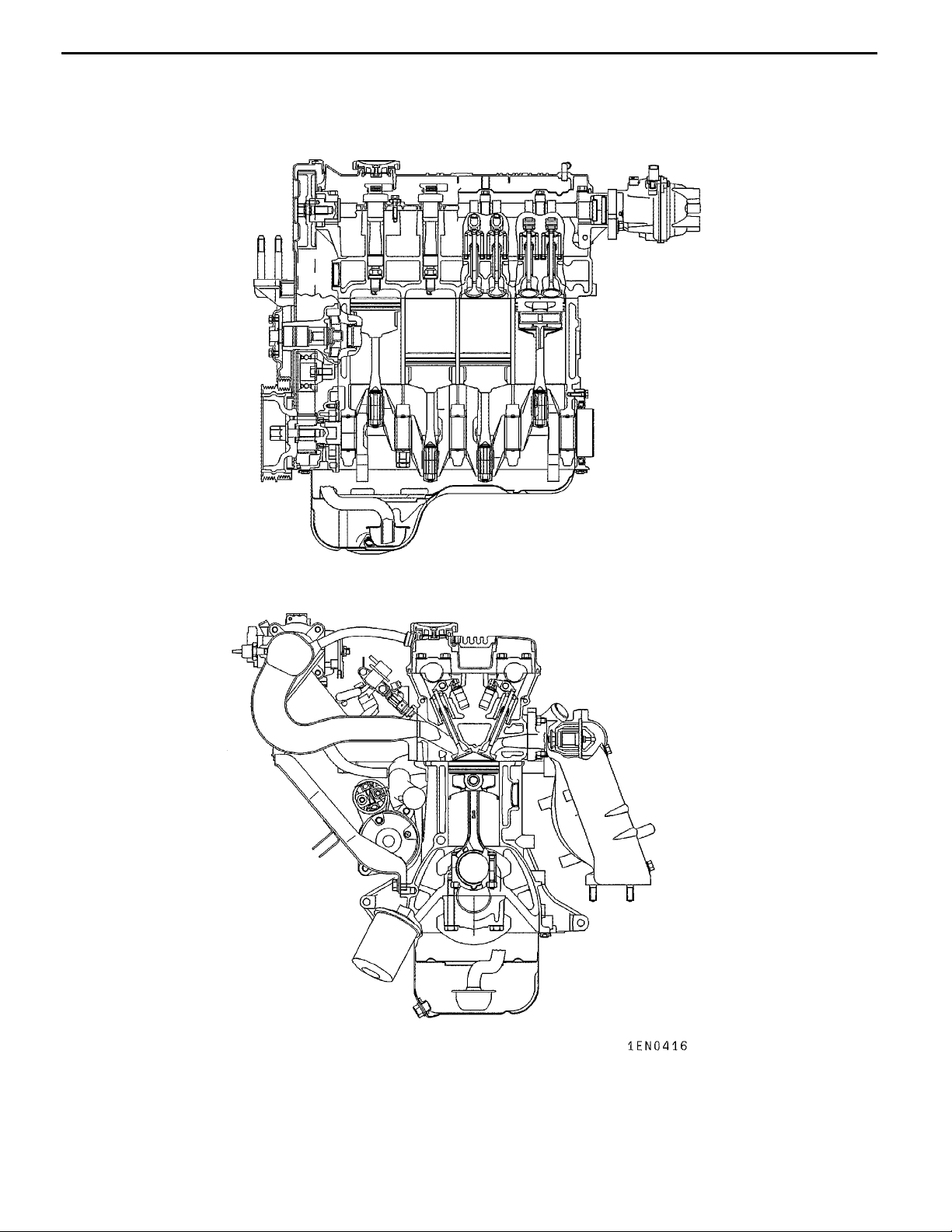
ENGINE
4G1 SERIES
CONTENTS
11A-0-1
GENERAL INFORMATION 11A-0-3
1. SPECIFICATIONS 11A-1-1
SERVICE SPECIFICATIONS 11A-1-1
REWORK DIMENSIONS 11A-1-3
TORQUE SPECIFICATIONS 11A-1-4
NEW TIGHTENING METHOD-BY USE OF BOLTS TO BE
TIGHTENED IN PLASTIC AREA 11A-1-6
SEALANT 11A-1-6
FORM-IN-PLACE GASKET 11A-1-7
2. SPECIAL TOOLS 11A-2-1
3. ALTERNATOR AND IGNITION SYSTEM 11A-3-1
4. TIMING BELT 11A-4-1
5. FUEL AND EMISSION CONTROL SYSTEMS 11A-5-1
5a. INTAKE MANIFOLD AND THROTTLE BODY (GDI) 11A-5a-1
5b. EXHAUST MANIFOLD (GDI) 11A-5b-1
6. WATER PUMP AND WATER HOSE 11A-6-1
........................................................
......................................................
...........................................
.................................................
....................................
........................................
.....................................
................................
......................................
.................................................
........................
...................
.........
.................................
.............................
7. INTAKE AND EXHAUST MANIFOLDS 11A-7-1
7a. FUEL SYSTEM (GDI) 11A-7a-1
8. ROCKER ARMS AND CAMSHAFTS 11A-8-1
8a. ROCKER ARMS AND CAMSHAFTS (GDI) 11A-8a-1
9. CYLINDER HEAD AND VALVES 11A-9-1
10. OIL PUMP AND OIL PAN 11A-10-1
11. PISTONS AND CONNECTING RODS 11A-11-1
12. CRANKSHAFT AND CYLINDER BLOCK 11A-12-1
E
E
Nov. 1995Mitsubishi Motors Corporation
Aug. 2000Mitsubishi Motors Corporation Revised
.........................................
.................................
.......................................
PWEE9520
PWEE9520-D
..........................
............................
..................
..........................
.....................

11A-0-2
NOTES
E
Nov. 1995Mitsubishi Motors Corporation
PWEE9520

4G1 ENGINE (E-W) -
GENERAL INFORMATION
General Information
11A-0-3
E
Nov. 1995Mitsubishi Motors Corporation
PWEE9520
11A-0-4
4G1 ENGINE (E-W) -
General Information
E
Nov. 1995Mitsubishi Motors Corporation
PWEE9520
4G1 ENGINE (E-W) -
General Information
Descriptions 4G13 12-VALVE- CARBURETOR 4G13 12-VALVE- MPI
Type In-line OHV, SOHC In-line OHV, SOHC
Number of cylinders 4 4
Combustion chamber Pentroof type Pentroof type
11A-0-5
Total displacement dm
3
1,299 1,299
Cylinder bore mm 71.0 71.0
Piston stroke mm 82.0 82.0
Compression ratio 9.5 9.5
Number of Intake 8 8
valves
Exhaust 4 4
V alve timing Intake opens BTDC 14
Intake closes ABDC 48
Exhaust opens BBDC 55
Exhaust closes ATDC 13
_
_
_
_
BTDC 19
ABDC 43
BBDC 60
ATDC 8
_
_
_
_
Lubrication system Pressure feed, full-flow filtration Pressure feed, full-flow filtration
Oil pump type Trochoid type Trochoid type
Cooling system Water-cooled, forced circulation Water-cooled, forced circulation
Water pump type Centrifugal impeller type Centrifugal impeller type
E
E
Nov. 1995Mitsubishi Motors Corporation
Dec. 1998Mitsubishi Motors Corporation Revised
PWEE9520
PWEE9520-A

11A-0-6
4G1 ENGINE (E–W) – General Information
Descriptions 4G13 16-VALVE–CARBURETOR 4G13 16-VALVE–MPI
Type In-line OHV, SOHC In-line OHV, SOHC
Number of cylinders 4 4
Combustion chamber Pentroof type Pentroof type
Total displacement dm
3
1,299 1,299
Cylinder bore mm 71.0 71.0
Piston stroke mm 82.0 82.0
Compression ratio 9.5 10, 9.5*
Number of
Intake 8 8
1
valves
Exhaust 8 8
Valve timing Intake opens BTDC 12_ BTDC 17_
Intake closes ABDC 48_ ABDC 39_
Exhaust opens BBDC 48_ BBDC 49_
Exhaust closes ATDC 12_ ATDC 7_
Lubrication system Pressure feed, full-flow filtration Pressure feed, full-flow filtration
Oil pump type Trochoid type Trochoid type
Cooling system Water-cooled, forced circulation Water-cooled, forced circulation
Water pump type Centrifugal impeller type Centrifugal impeller type
*1: LANCER for General Export
E
E
Nov. 1995Mitsubishi Motors Corporation
Feb. 2001Mitsubishi Motors Corporation Revised
PWEE9520
PWEE9520-E

4G1 ENGINE (E–W) – General Information
11A-0-7
Descriptions 4G15–
CARBURETTOR
4G15–MPI
12-VALVE
4G15–MPI
16-VALVE
4G15–GDI
Type In-line OHV, SOHC In-line OHV, SOHC In-line OHV, DOHC In-line OHV, DOHC
Number of cylinders 4 4 4 4
Combustion chamber Semi spherical type Semi spherical type Pentroof type Pentroof + Curved
piston head
Total displacement dm
3
1,468 1,468 1,468 1,468
Cylinder bore mm 75.5 75.5 75.5 75.5
Piston stroke mm 82.0 82.0 82.0 82.0
Compression ratio 9.0 9.0 9.5 11.0
Number
f
of valves
Intake 8 8 8 8
Exhaust 4 4 8 8
Valve
timing
Intake opens BTDC 14_ BTDC 14_ ,
BTDC 13_*
Intake closes ABDC 48_ ABDC 48_ ,
ABDC 47_*
1
1
BTDC 16_ BTDC 12_
ABDC 40_ ABDC 44_
Exhaust
opens
Exhaust
closes
Lubrication system Pressure feed,
BBDC 55_ BBDC 55_ ,
BBDC 56_*
ATDC 13_ ATDC 13_ ,
ATDC 8_*
1
Pressure feed,
full-flow filtration
full-flow filtration
1
BBDC 45_ BBDC 48_
ATDC 15_ ATDC 12_
Pressure feed,
full-flow filtration
Pressure feed,
full-flow filtration
Oil pump type Trochoid type Trochoid type Trochoid type Trochoid type
Cooling system Water-cooled,
forced circulation
Water pump type Centrifugal impeller
type
Water-cooled,
forced circulation
Centrifugal impeller
type
Water-cooled,
forced circulation
Centrifugal impeller
type
Water-cooled,
forced circulation
Centrifugal impeller
type
*1: Special low-emission engines on vehicles for Australia
E
E
Nov. 1995Mitsubishi Motors Corporation
Feb. 2001Mitsubishi Motors Corporation Revised
PWEE9520
PWEE9520-E

11A-0-8
4G1 ENGINE (E–W) – General Information
Descriptions 4G18 16-VALVE–CARBURETOR 4G18 16-VALVE–MPI
Type In-line OHV, SOHC In-line OHV, SOHC
Number of cylinders 4 4
Combustion chamber Pentroof type Pentroof type
Total displacement dm
3
1,584 1,584
Cylinder bore mm 76.0 76.0
Piston stroke mm 87.3 87.3
Compression ratio 9.5 9.5, 10*1*
Number of
Intake 8 8
2
valves
Exhaust 8 8
Valve timing Intake opens BTDC 12_ BTDC 17_ , BTDC 9_*1 , BTDC 17_*
Intake closes ABDC 48_ ABDC 39_ , ABDC 51_*1 , ABDC 43_*
Exhaust opens BBDC 48_ BBDC 49_ , BBDC 49_*1 , BBDC 53_*
Exhaust closes ATDC 12_ ATDC 7_ , ATDC 15_*1 , ATDC 7_*
Lubrication system Pressure feed, full-flow filtration Pressure feed, full-flow filtration
Oil pump type Trochoid type Trochoid type
Cooling system Water-cooled, forced circulation Water-cooled, forced circulation
Water pump type Centrifugal impeller type Centrifugal impeller type
2
2
2
2
*1: SPACE STAR for Europe
2
*
: LANCER for General Export
E
E
Nov. 1995Mitsubishi Motors Corporation
Feb. 2001Mitsubishi Motors Corporation Revised
PWEE9520
PWEE9520-E

4G1 ENGINE (E–W) – Specifications
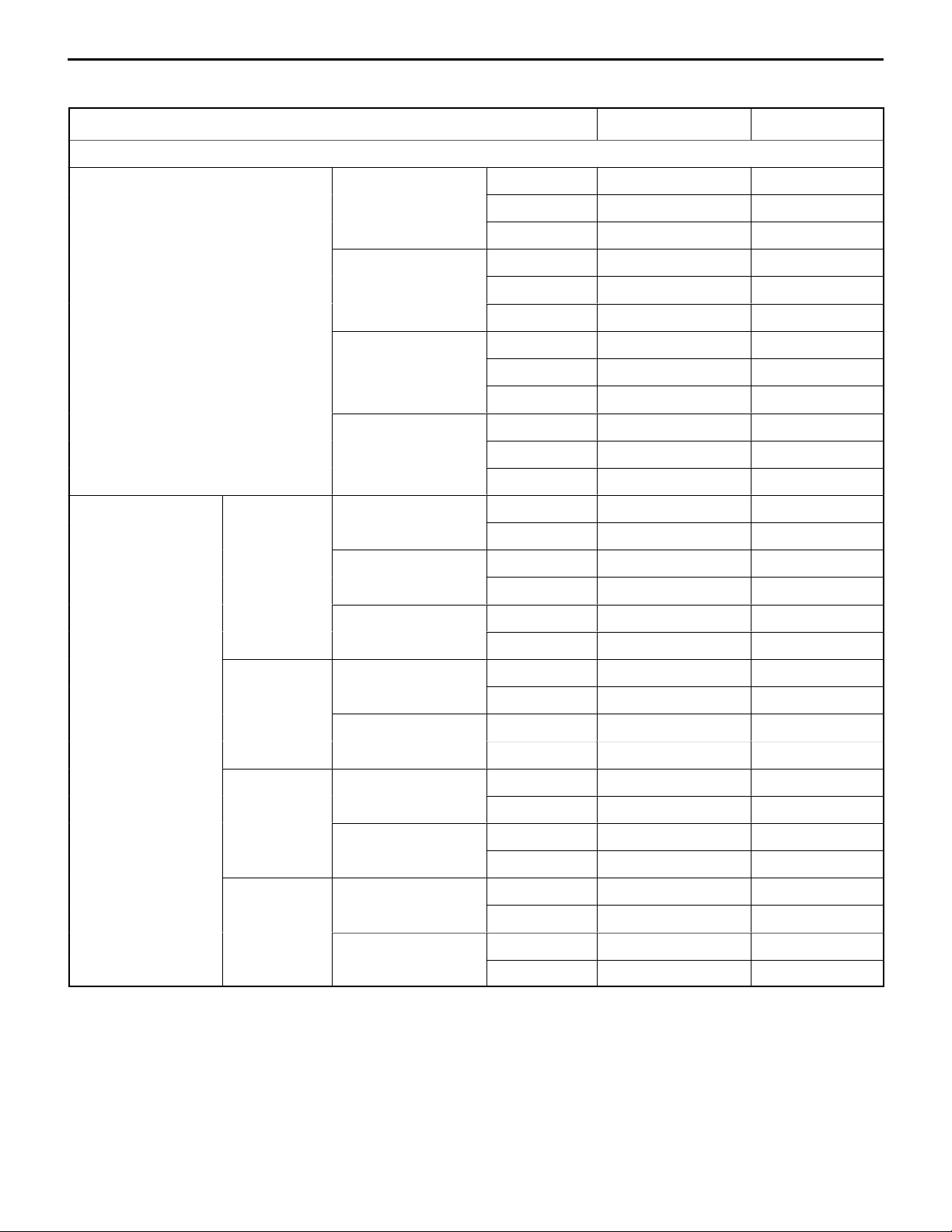
1. SPECIFICATIONS
SERVICE SPECIFICATIONS
Item Standard Limit
Rocker arms and camshaft
Camshaft cam
height mm
SOHC 12-VALVE Intake (primary) 38.78 38.28
Intake (secondary) 38.78 38.28
1
2
39.01 38.51
38.97 38.47
SOHC 16-VALVE*
Exhaust*
Exhaust*
3
Intake 36.99 36.49
Exhaust 36.85 36.35
SOHC 16-VALVE*
4
Intake 36.86 36.36
Exhaust 36.68 36.18
SOHC 16-VALVE*
5
Intake 37.30 36.80
Exhaust 37.16 36.66
SOHC 16-VALVE*
6
Intake 37.17 36.67
11A-1-1
Exhaust 36.99 36.49
DOHC Intake 34.67 34.17
Exhaust 34.26 33.76
DOHC GDI Intake 34.85 34.35
Exhaust 34.59 34.09
Camshaft journal diameter mm SOHC 45.93 –45.94 –
SOHC 16-VALVE*
7
44.93–44.94 –
DOHC 25.95–25.97 –
Cylinder head and valves
Flatness of cylinder head gasket surface mm 0.05 or less –
Cylinder head gasket surface grinding limit (including grinding of
– 0.2
cylinder block gasket surface) mm
Cylinder head overall height mm SOHC 12-VALVE 106.9 –107.1 –
SOHC 16-VALVE 119.9–120.1 –
DOHC 131.9–132.1 –
Cylinder head bolt nominal length mm – 103.2
Valve margin mm Intake 1.0 0.5
Exhaust 1.5 1.0
Valve stem diameter mm SOHC 12-VALVE 6.6 –
SOHC 16-VALVE 5.5 –
DOHC 5.5 –
*1: With low pollution system
2
: Without low pollution system
*
3
: Except 2001 model front wheel drive vehicles
*
4
: 2001 model front wheel drive vehicles for Europe
*
5
: 2001 model front wheel drive vehicles for General Export
*
6
: 2002 model front wheel drive vehicles for Europe
*
7
: SOHC 16-VALVE MPI for Europe
*
E
E
Nov. 1995Mitsubishi Motors Corporation
Feb. 2001Mitsubishi Motors Corporation Revised
PWEE9520
PWEE9520-E
11A-1-2
4G1 ENGINE (E- W) -
Specifications
Item LimitStandard
V alve stem-to-guide SOHC 12-VALVE
clearance mm
SOHC 16-VALVE
Intake 0.020- 0.050 0.10
Exhaust 0.035- 0.050 0.15
Intake 0.020 - 0.047 0.10
Exhaust 0.030 - 0.057 0.15
DOHC
Intake 0.020- 0.047 0.10
Exhaust 0.030- 0.062 0.15
V alve face angle 45°- 45.5
V alve stem projec- SOHC 12-VALVE
tion mm
SOHC 16-VALVE
Intake 43.70 44.20
Exhaust 43.30 43.80
Intake 53.21 53.71
Exhaust 54.10 54.60
DOHC
Intake 48.80 49.30
Exhaust 48.70 49.20
Overall valve length SOHC 12-VALVE
mm
SOHC 16-VALVE
Intake 100.75 100.25
Exhaust 101.05 105.55
Intake 111.56 111.06
Exhaust 114.71 114.21
°
-
DOHC
Intake 106.35 105.85
Exhaust 106.85 106.35
V alve spring free SOHC 12-VALVE
height mm
Intake 46.1 45.6
Exhaust 46.8 46.3
SOHC 16-VALVE 50.9 50.4
DOHC 49.1 48.6
Valve spring load/ SOHC 12-VALVE
installed height N/
mm
mm
Intake 226/40.0 -
Exhaust 284/39.6 -
SOHC 16-VALVE 216/44.2 -
DOHC 177/40.0 -
Valve spring squareness 2
°
Valve seat contact width mm 0.9- 1.3 -
V alve guide internal diameter mm
SOHC 12-VALVE 6.6 -
SOHC 16-VALVE 5.5 -
DOHC 5.5 -
Valve guide projection mm
SOHC 12-VALVE 17.0 -
SOHC 16-VALVE 23.0 -
°
4
DOHC 23.0 -
Oil pump and oil pan
Oil pump tip clearance mm 0.06- 0.18 -
Oil pump side clearance mm 0.04 - 0.10 -
Oil pump body clearance mm 0.10- 0.18 0.35
E
E
Nov. 1995Mitsubishi Motors Corporation
Apr. 2000Mitsubishi Motors Corporation Revised
PWEE9520
PWEE9520-C
4G1 ENGINE (E- W) -
Specifications
Item Standard Limit
Pistons and connecting rods
11A-1-2a
Piston outside diameter mm
4G13 71.0 -
4G15 75.5 -
4G18 76.0 -
Piston ring side clearance mm
No. 1 ring 0.03-0.07 -
No. 2 ring 0.02- 0.06 -
Piston ring end gap
clearance
No. 1 ring 0.20- 0.35 0.8
No. 2 ring 0.35- 0.50 0.8
Oil ring
4G13, 4G15 0.20 - 0.50 1.0
4G18 0.10 -0.40 1.0
Piston pin O. D. mm 18.0 -
Piston pin press-in load (at room temperature) N 4,900 - 14,700 -
Crankshaft pin oil clearance mm 0.02- 0.04 0.1
Connecting rod big end side clearance mm 0.10 - 0.25 0.4
Crankshaft and cylinder block
Crankshaft end play mm 0.05- 0.18 0.25
Crankshaft journal diameter mm 48.0 -
Crankshaft pin diameter mm 42.0 -
Crankshaft journal oil clearance mm 0.02- 0.04 0.1
Cylinder block gasket surface flatness mm 0.05 or less -
Cylinder block gasket surface grinding limit (including grinding of
- 0.2
cylinder head gasket surface) mm
Cylinder block overall height mm 256 -
Cylinder bore cylindricity mm 0.01 -
Cylinder bore I. D. mm
4G13 71.0 -
4G15 75.5 -
4G18 76.0 -
Piston-to-cylinder clearance mm 0.02 - 0.04 -
E
E
Nov. 1995Mitsubishi Motors Corporation
Aug. 2000Mitsubishi Motors Corporation Revised
PWEE9520
PWEE9520-D

11A-1-2b
4G1 ENGINE (E-W) -
Specifications
Intentionally blank
E
E
E
Nov. 1995Mitsubishi Motors Corporation
Dec. 1998Mitsubishi Motors Corporation AddedPWEE9520-A
Dec. 1998Mitsubishi Motors Corporation Added
PWEE9520
PWEE9520-A
4G1 ENGINE (E–W) – Specifications
mm
<4G13>
<4G18>
REWORK DIMENSIONS
Item Standard Limit
Cylinder head and valves
11A-1-3
Cylinder head oversize valve guide
hole diameter mm
Oversize valve seat
SOHC
ring hole diametermm12-VALVE
SOHC 12-VALVE 0.05 O. S. 12.040–12.058 –
0.25 O. S. 12.240–12.258 –
0.50 O. S. 12.490–12.508 –
SOHC 16-VALVE 0.05 O. S. 10.550–10.568 –
0.25 O. S. 10.750–10.768 –
0.50 O. S. 11.000–11.018 –
DOHC 0.05 O. S. 10.550–10.568 –
0.25 O. S. 10.750–10.768 –
0.50 O. S. 11.000–11.018 –
DOHC GDI 0.05 O. S. 10.610–10.620 –
0.25 O. S. 10.810–10.820 –
0.50 O. S. 11.060–11.070 –
Intake (primary) 0.3 O. S. 27.300–27.325 –
0.6 O. S. 27.600–27.625 –
Intake (secondary) 0.3 O. S. 32.300–32.325 –
0.6 O. S. 32.600–32.625 –
Exhaust 0.3 O. S. 35.300–35.325 –
0.6 O. S. 35.600–35.625 –
SOHC
16-VALVE
<4G13>
Intake 0.3 O. S. 28.300–28.321 –
0.6 O. S. 28.600–28.621 –
Exhaust 0.3 O. S. 26.300–26.321 –
0.6 O. S. 26.600–26.621 –
SOHC
16-VALVE
<4G18>
Intake 0.3 O. S. 30.300–30.321 –
0.6 O. S. 30.600–30.621 –
Exhaust 0.3 O. S. 28.300–28.321 –
0.6 O. S. 28.600–28.621 –
DOHC Intake 0.3 O. S. 31.300–31.325 –
0.6 O. S. 31.600–31.625 –
Exhaust 0.3 O. S. 27.800–27.825 –
0.6 O. S. 28.100–28.125 –
E
E
Nov. 1995Mitsubishi Motors Corporation
Feb. 2001Mitsubishi Motors Corporation Revised
PWEE9520
PWEE9520-E

11A-1-4
4G1 ENGINE (E–W) – Specifications
TORQUE SPECIFICATIONS
Item Nm
Alternator and ignition system
Water pump pulley bolt 9
Alternator brace bolt (alternator side) 22
Alternator brace bolt (tightened with water pump) 23
Alternator pivot bolt 44
Oil level gauge guide bolt (Flange) 23
Oil level gauge guide bolt (Washer) 19
Crankshaft bolt (M12) 125
Crankshaft bolt (M14) 181
Spark plug 25
Distributor bolt 11
Ignition coil bolt 10
Ignition failure sensor bolt 5
Camshaft position sensor bolt 9
Camshaft position sensor support bolt 13
Camshaft position sensing cylinder bolt 21
Timing belt
Timing belt cover bolt 11
Timing belt tensioner bolt 23
Crankshaft angle sensor bolt 9
Bracket bolt 21
Engine support bracket bolt (M8) 21
Engine support bracket bolt, nut (M10) 35
Idler pulley bolt 35
Camshaft sprocket bolt 88
Fuel and emission control system
Vacuum pipe & hose bolt 9
Delivery pipe bolt 11
Fuel pressure regulator bolt 9
Throttle body bolt 18
Hose clamp bolt 10
Fuel pump bolt (SOHC 12-VALVE–CARBURETOR) 12
Fuel pump bolt (SOHC 16-VALVE–CARBURETOR) 19
Breather tube clamp bolt 22
Carburetor bolt 17
Air temperature sensor 13
Cover bolt (Except M8 × 16) 12
E
E
Nov. 1995Mitsubishi Motors Corporation
Apr. 2003Mitsubishi Motors Corporation Revised
PWEE9520
PWEE9520-G

4G1 ENGINE (E–W) – Specifications
Item Nm
Cover bolt (M8 × 16) 18
EGR valve bolt 21
11A-1-4a
E
E
Nov. 1995Mitsubishi Motors Corporation
Apr. 2003Mitsubishi Motors Corporation Revised
PWEE9520
PWEE9520-G

11A-1-4b
4G1 ENGINE (E–W) – Specifications
Intentionally blank
E
E
Nov. 1995Mitsubishi Motors Corporation
Aug. 2001Mitsubishi Motors Corporation Added
PWEE9520
PWEE9520-F

4G1 ENGINE (E- W) -
Specifications
Item Nm
Intake manifold and throttle body (GDI)
Accelerator cable bolt 10
Throttle body bolt 19
Air intake plenum resonator bolt 10
Power plant stay right bolt 49
Intake manifold stay bolt 30
EGR valve bolt 19
EGR valve support bolt 19
EGR valve support nut 24
Intake manifold bolt, nut 20
Exhaust manifold (GDI)
Oxygen sensor 44
Exhaust manifold cover bolt 30
Exhaust manifold bracket bolt 35
11A-1-5
Exhaust manifold nut (M8) 18
Exhaust manifold nut (M10) 29
Power plant stay left bolt 35
Water pump and water hose
Water inlet fitting bolt 22
Water inlet pipe bolt (M8) 12
Water inlet pipe bolt (M10) 25
Fitting bolt 23
Water outlet fitting bolt (Front wheel drive) 23
Water outlet fitting bolt (Rear wheel drive) 18
Thermostat case bolt 23
Thermo valve 27
Engine coolant temperature gauge unit 11
Engine coolant temperature sensor 29
Water pump bolt 13
Exhaust manifold and intake manifold
Boost sensor bolt 5
Solenoid valve assembly bolt 9
Intake manifold bolt, nut 17
Intake manifold stay bolt <MPI> (M8) 17
Intake manifold stay bolt <MPI> (M10) 31
Intake manifold stay bolt <carburetor> 30
Engine hanger bolt 19
Exhaust manifold cover bolt 29
E
E
Nov. 1995Mitsubishi Motors Corporation
Aug. 2000Mitsubishi Motors Corporation Revised
PWEE9520
PWEE9520-D

11A-1-5a
Item Nm
Exhaust manifold nut (M8) 17
Exhaust manifold nut (M10) 29
Exhaust manifold bracket A bolt 35
Exhaust manifold bracket B bolt 35
Power plant stay right bolt 49
Power plant stay left bolt 35
Oxygen sensor 44
Fuel system (GDI)
Fuel pipe bolt 12
Fuel pump bolt 4.9®17±2
Flange bolt 24
Harness bracket bolt 9.8
Injector holder bolt 23
Delivery pipe and injector bolt 12
4G1 ENGINE (E- W) -
4G1 ENGINE (E- W) -
4G1 ENGINE (E- W) -
Specifications
Specifications
Specifications
Rocker arms and camshaft
Fuel pump cover bolt 12
Rocker cover bolt <SOHC> 3.5
Rocker cover bolt <DOHC> 4
Rocker shaft assembly bolt 31
Adjusting screw 15
Bearing cap bolt (M6) 11
Bearing cap bolt (M8) 24
Rocker arms and camshaft (GDI)
Engine hanger bolt 19
Rocker cover bolt 3.5
Beam camshaft cap bolt (M6) 11
Beam camshaft cap bolt (M8) 25
Cylinder head and valves
Cylinder head bolt 20 + 90_+90
Tighten to 49 Nm, then completely loosen and retighten as described.
_
Oil pump and oil pan
Transmission stay bolt 23
Oil pan bolt (M6) 7
Oil pan bolt (M8) 24
Drain plug 39
Oil screen bolt 19
Front case bolt 14
Relief plug 44
E
E
Nov. 1995Mitsubishi Motors Corporation
Aug. 2000Mitsubishi Motors Corporation Revised
PWEE9520
PWEE9520-D

4G1 ENGINE (E- W) -
Specifications
Item Nm
Oil pump cover bolt 10
Pistons and connecting rods
11A-1-5b
Connecting rod nut 17 + 90_to 100
Crankshaft and cylinder block
Flywheel bolt 132
Drive plate bolt <Except GDI> 132
Drive plate bolt <GDI> 98
Rear plate bolt 10
Bell housing cover bolt 10
Rear oil seal case bolt 11
Bearing cap bolt 34 + 30_to 34
Oil pressure switch 19
Knock sensor 23
_
_
E
E
Nov. 1995Mitsubishi Motors Corporation
Aug. 2000Mitsubishi Motors Corporation Revised
PWEE9520
PWEE9520-D

11A-1-6
4G1 ENGINE (E- W) -
Specifications
NEW TIGHTENING METHOD USING PLASTIC REGION TIGHTENING BOLTS
Parts of the engine use plastic region tightening bolts. The tightening procedure for these is different
from that of conventional bolts and is described in relevant parts of this manual. Note that plastic region
tightening bolts have fixed service limits. These limits are indicated in relevant parts of this manual and
must be strictly observed.
D
Plastic region tightening bolts are used for the following applications:
(1) Cylinder head bolts
(2) Connecting rod cap bolts
(3) Bearing cap bolt
D
The tightening procedure is basically as follows:
After tightening a bolt to the specified torque, tighten it by a further 90_+90_,90_–100_or 30_–34_.
The exact tightening procedure differs depending on the bolt and is described in relevant parts of
this manual.
SEALANTS
Item Specified sealant Quantity
Cam position sensor support Mitsubishi Genuine Part No. MD970389 or equivalent As required
Water pump Mitsubishi Genuine Part No. MD970389 or equivalent As required
Thermo valve Mitsubishi Genuine Part No. MD970389 or equivalent As required
Thermostat housing Mitsubishi Genuine Part No. MD970389 or equivalent As required
Water outlet fitting Mitsubishi Genuine Part No. MD970389 or equivalent As required
Engine coolant temperature sensor 3M Nut Locking Part No. 4171 or equivalent As required
Engine coolant temperature gauge unit 3M ATD Part No. 8660 or equivalent As required
Camshaft bearing cap 3M ATD Part No. 8660 or equivalent As required
Semi-circular packing 3M ATD Part No. 8660 or equivalent As required
Rocker cover 3M ATD Part No. 8660 or equivalent As required
Beam camshaft cap Mitsubishi Genuine Part No. MD970389 or equivalent As required
Oil pump case Mitsubishi Genuine Part No. MD970389 or equivalent As required
Oil pan Mitsubishi Genuine Part No. MD970389 or equivalent As required
Oil pressure switch 3M ATD Part No. 8660 or equivalent As required
Rear oil seal case Mitsubishi Genuine Part No. MD970389 or equivalent As required
Drive plate bolt 3M Nut Locking Part No. 4171 or equivalent As required
E
E
Apr. 2000Mitsubishi Motors Corporation
Aug. 2000Mitsubishi Motors Corporation Revised
PWEE9520
PWEE9520-D

4G1 ENGINE (E-W) -
Specifications
11A-1-7
FORM-IN-PLACE GASKET
The engine has several areas where the form-in-place gasket (FIPG) is in use. To ensure that the gasket
fully serves its purpose, it is necessary to observe some precautions when applying the gasket. Bead
size, continuity and location are of paramount importance. Too thin a bead could cause leaks. Too thick
a bead, on the other hand, could be squeezed out of location, causing blocking or narrowing of the
fluid feed line. To eliminate the possibility of leaks from a joint, therefore, it is absolutely necessary to
apply the gasket evenly without a break, while observing the correct bead size.
The FIPG used in the engine is a room temperature vulcanization (RTV) type and is supplied in a 100-gram
tube (Part No. MD970389 or MD997110). Since the RTV hardens as it reacts with the moisture in the
atomospheric air, it is normally used in the metallic flange areas. The FIPG, Part No. MD970389, can
be used for sealing both engine oil and coolant, while Part No. 997110 can only be used for engine
oil sealing.
Disassembly
The parts assembled with the FIPG can be easily disassembled without use of a special method. In
some cases, however, the sealant between the joined surfaces may have to be broken by lightly striking
with a mallet or similar tool. A flat and thin gasket scraper may be lightly hammered in between the
joined surfaces. In this case, however, care must be taken to prevent damage to the joined surfaces.
For removal of the oil pan, the special tool “Oil Pan Remover” (MD998727) is available. Be sure to use
the special tool to remove the oil pan. <Except aluminium die-cast oil pans>
Surface Preparation
Thoroughly remove all substances deposited on the gasket application surfaces, using a gasket scraper
or wire brush. Check to ensure that the surfaces to which the FIPG is to be applied is flat. Make sure
that there are no oils, greases an d foreign substances deposited on the application surfaces. Do not
forget to remove the old sealant remained in the bolt holes.
Form-In-Place Gasket Application
When assembling parts with the FIPG, you must observe some precautions, but the procedures is very
simple as in the case of a conventional precut gasket.
Applied FIPG bead should be of the specified size and without breaks. Also be sure to encircle the
bolt hole circumference with a completely continuous bead. The FIPG can be wiped away unless it is
hardened. While the FIPG is still moist (in less than 15 minutes), mount the parts in position. When
the parts are mounted, make sure that the gasket is applied to the required area only. In addition, do
not apply any oil or water to the sealing locations or start the engine until a sufficient amount of time
(about one hour) has passed after installation is completed.
The FIPG application procedure may vary on different areas. Observe the procedure described in the
text when applying the FIPG.
E
Nov. 1995Mitsubishi Motors Corporation
PWEE9520

NOTES
4G1 ENGINE (E- W) -
Special Tools
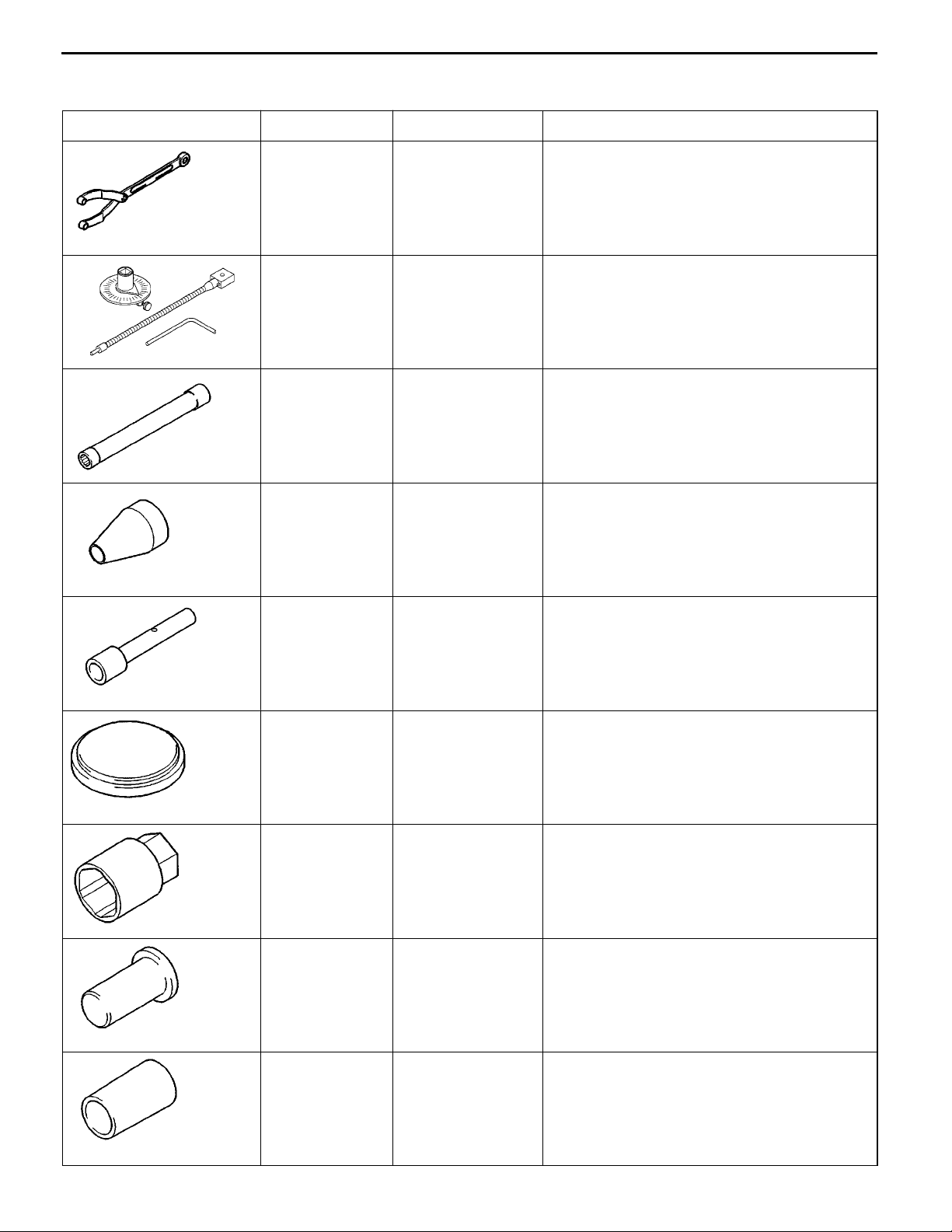
2. SPECIAL TOOLS
Tool Number Name Use
MB990767 End yoke holder Holding camshaft sprocket when loosening or
MB991614 Angle gauge Installation of crankshaft bearing caps
11A-2-1
tightening bolt (used with MD998715)
MB991653 Cylinder head bolt
wrench (10)
MB991659 Guide-D Guide for removal and press-fitting of piston
MB991671 Valve stem
installer
MD998011 Crankshaft rear oil
seal installer
Removal and installation of cylinder head bolts
pins
Press-fitting of valve stem seals
(SOHC 16-VALVE, DOHC)
Installation of crankshaft rear oil seal
MD998054 Oil pressure switch
wrench
MD998304 Crankshaft front oil
seal installer
MD998305 Crankshaft front oil
seal guide
E
E
Nov. 1995Mitsubishi Motors Corporation
Aug. 2000Mitsubishi Motors Corporation Revised
PWEE9520
PWEE9520-D
Removal and installation of oil pressure switch
Installation of crankshaft front oil seal
Guide for installation of crankshaft front oil seal
11A-2-2
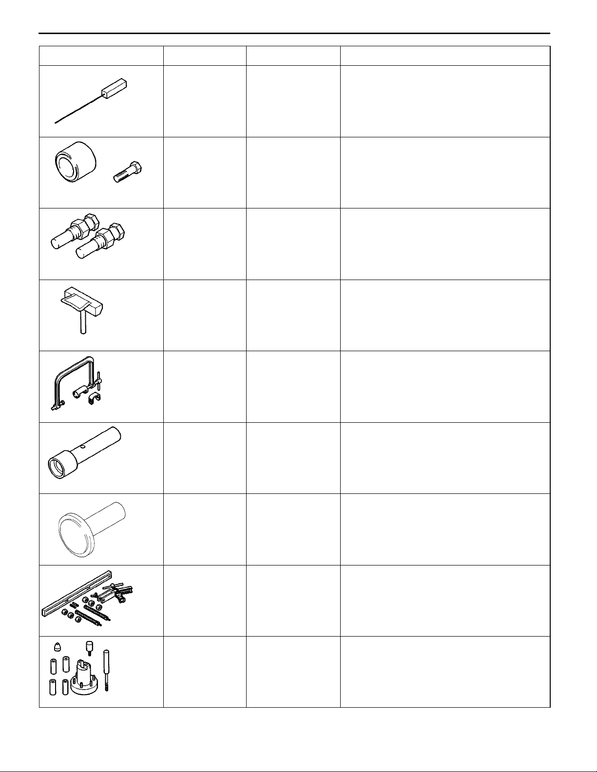
Tool UseNameNumber
MD998442 Air bleed wire Testing of automatic lash adjusters
4G1 ENGINE (E- W) -
Special Tools
(DOHC)
MD998713 Camshaft oil seal
Installation of camshaft oil seal
installer
MD998715 Pin (2-off) Holding camshaft sprocket when loosening or
tightening bolt (used with MB990767)
MD998727 Oil pan remover Removal of oil pan
MD998735 Valve spring com-
Compression of valve springs
pressor
MD998760 Valve stem seal
installer
MD998762 Circular packing
installer
MD998772 Valve spring com-
pressor
MD998780 Piston pin setting
tool
Installation of valve stem seals
(SOHC 12-VALVE)
Installing of circular packing
Compression of valve springs
Removal and press-fitting of piston pins
E
E
Nov. 1995Mitsubishi Motors Corporation
Aug. 2000Mitsubishi Motors Corporation Revised
PWEE9520
PWEE9520-D
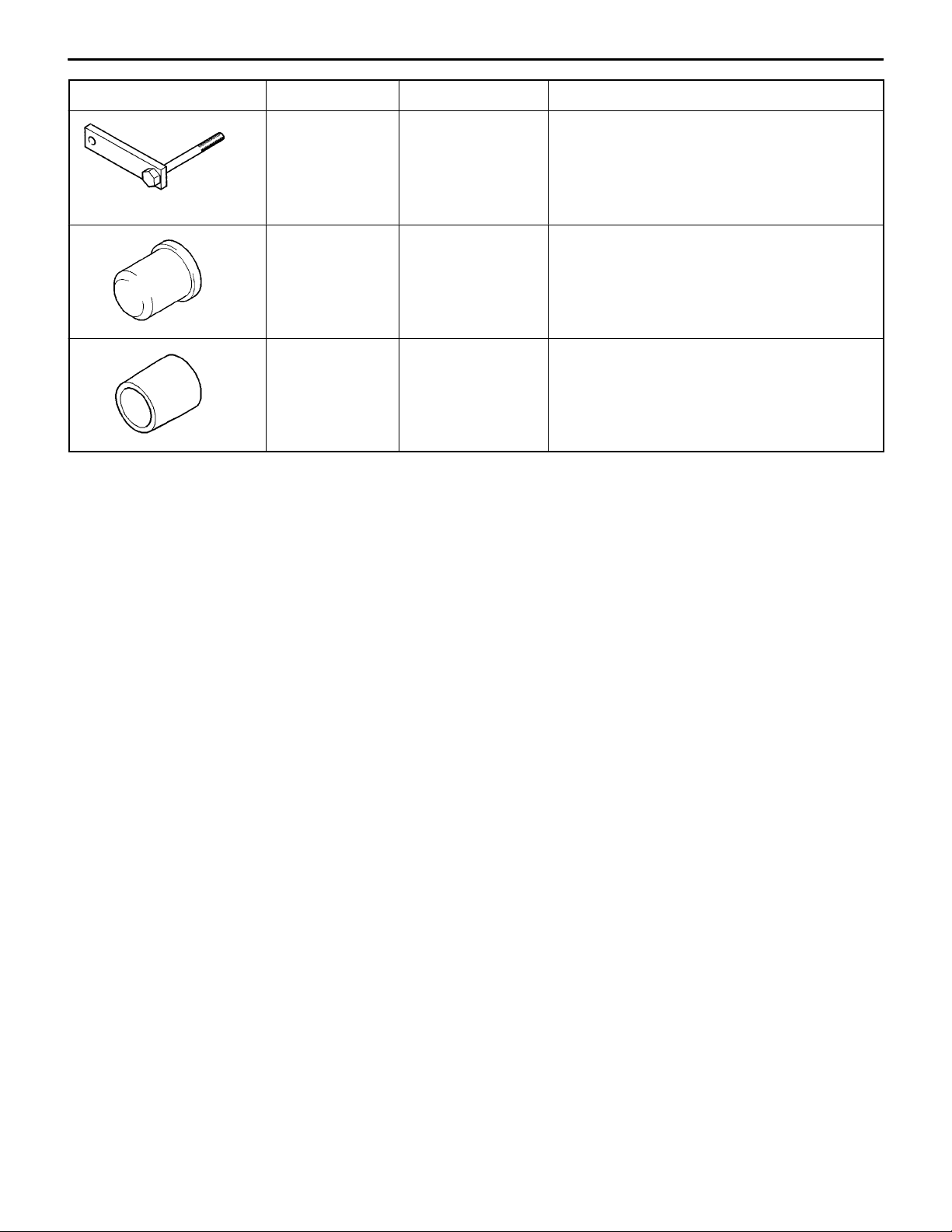
4G1 ENGINE (E–W) – Special Tools
Tool UseNameNumber
MD998781 Flywheel stopper Locking flywheel in fixed position
11A-2-3
MD998306 Crankshaft front oil
seal installer
MB991962 Crankshaft front oil
seal guide
Installation of crankshaft front oil seal
Guide for installation of crankshaft oil seal
E
E
Nov. 1995Mitsubishi Motors Corporation
Apr. 2003Mitsubishi Motors Corporation Revised
PWEE9520
PWEE9520-G
4G1 ENGINE (E–W) – Alternator and Ignition System
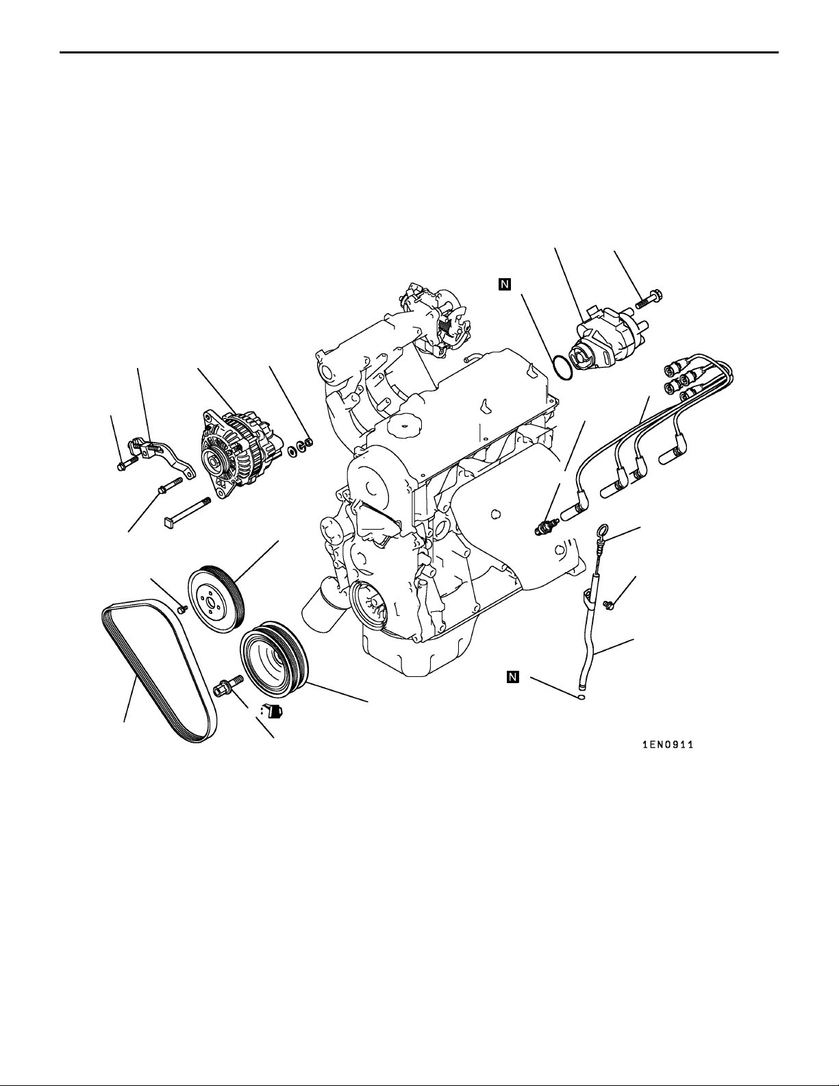
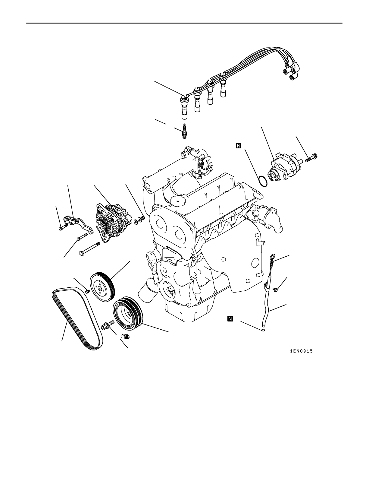
3. ALTERNATOR AND IGNITION SYSTEM
REMOVAL AND INSTALLATION <SOHC 12-VALVE>
11A-3-1
22 Nm
23 Nm
6
9 Nm
12
12 Nm
13
7
44 Nm
10
25 Nm
11
1
5
23 Nm
2
8
4
M12 125 Nm
M14 181 Nm
Removal steps
1. Oil level gauge
2. Oil level gauge guide
3. O-ring
4. Drive belt*
5. Water pump pulley
6. Alternator brace
7. Alternator
AA""BA 8. Crankshaft bolt
"BA 9. Crankshaft pulley
E
E
Nov. 1995Mitsubishi Motors Corporation
Apr. 2003Mitsubishi Motors Corporation Revised
9
PWEE9520
PWEE9520-G
3
10. Spark plug cable
11. Spark plug
"AA 12. Distributor
13. O-ring
NOTE
*: For details of adjustment, refer to the relevant model’s
chassis workshop manual.
11A-3-1a
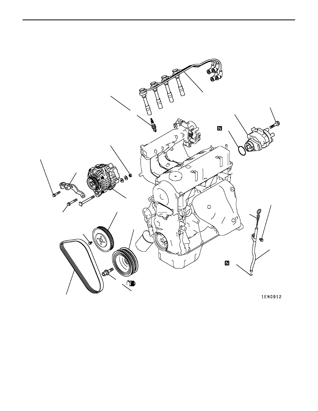
4G1 ENGINE (E–W) – Alternator and Ignition System
REMOVAL AND INSTALLATION <SOHC 16-VALVE – FRONT WHEEL DRIVE (WITH
DISTRIBUTOR)>
22 Nm
23 Nm
6
9 Nm
25 Nm
44 Nm
10
12 Nm
11
12
13
7
23 Nm
5
1
9
4
Removal steps
1. Oil level gauge
2. Oil level gauge guide
3. O-ring
4. Drive belt*
5. Water pump pulley
6. Alternator brace
7. Alternator
AA""BA 8. Crankshaft bolt
"BA 9. Crankshaft pulley
2
3
8
M12 125 Nm
M14 181 Nm
10. Spark plug cable
11. Spark plug
"AA 12. Distributor
13. O-ring
NOTE
*: For details of adjustment, refer to the relevant model’s
chassis workshop manual.
E
E
Nov. 1995Mitsubishi Motors Corporation
Apr. 2003Mitsubishi Motors Corporation Revised
PWEE9520
PWEE9520-G
4G1 ENGINE (E–W) – Alternator and Ignition System
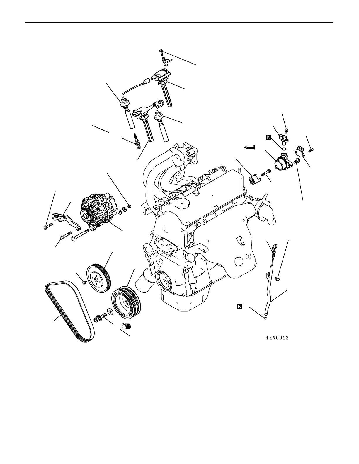
11A-3-1b
REMOVAL AND INSTALLATION <SOHC 16-VALVE – FRONT WHEEL DRIVE (WITH
CAM POSITION SENSOR)>
10 Nm
10
11
9 Nm
25 Nm
10
12
16
14
5 Nm
15
22 Nm
23 Nm
4
6
9 Nm
44 Nm
11
13
21 Nm
13 Nm
7
1
23 Nm
5
9
2
3
8
Removal steps
1. Oil level gauge
2. Oil level gauge guide
3. O-ring
4. Drive belt*
5. Water pump pulley
6. Alternator brace
7. Alternator
AA""BA 8. Crankshaft bolt
"BA 9. Crankshaft pulley
E
E
Nov. 1995Mitsubishi Motors Corporation
Apr. 2003Mitsubishi Motors Corporation Revised
M12 125 Nm
M14 181 Nm
NOTE
PWEE9520
PWEE9520-G
10. Spark plug cable
11. Ignition coil
12. Spark plug
13. Ignition failure sensor
(only vehicles for Europe)
14. Cam position sensor
"CA 15. Cam position sensor support
16. Cam position sensing cylinder
*: For details of adjustment, refer to the relevant model’s
chassis workshop manual.
11A-3-2
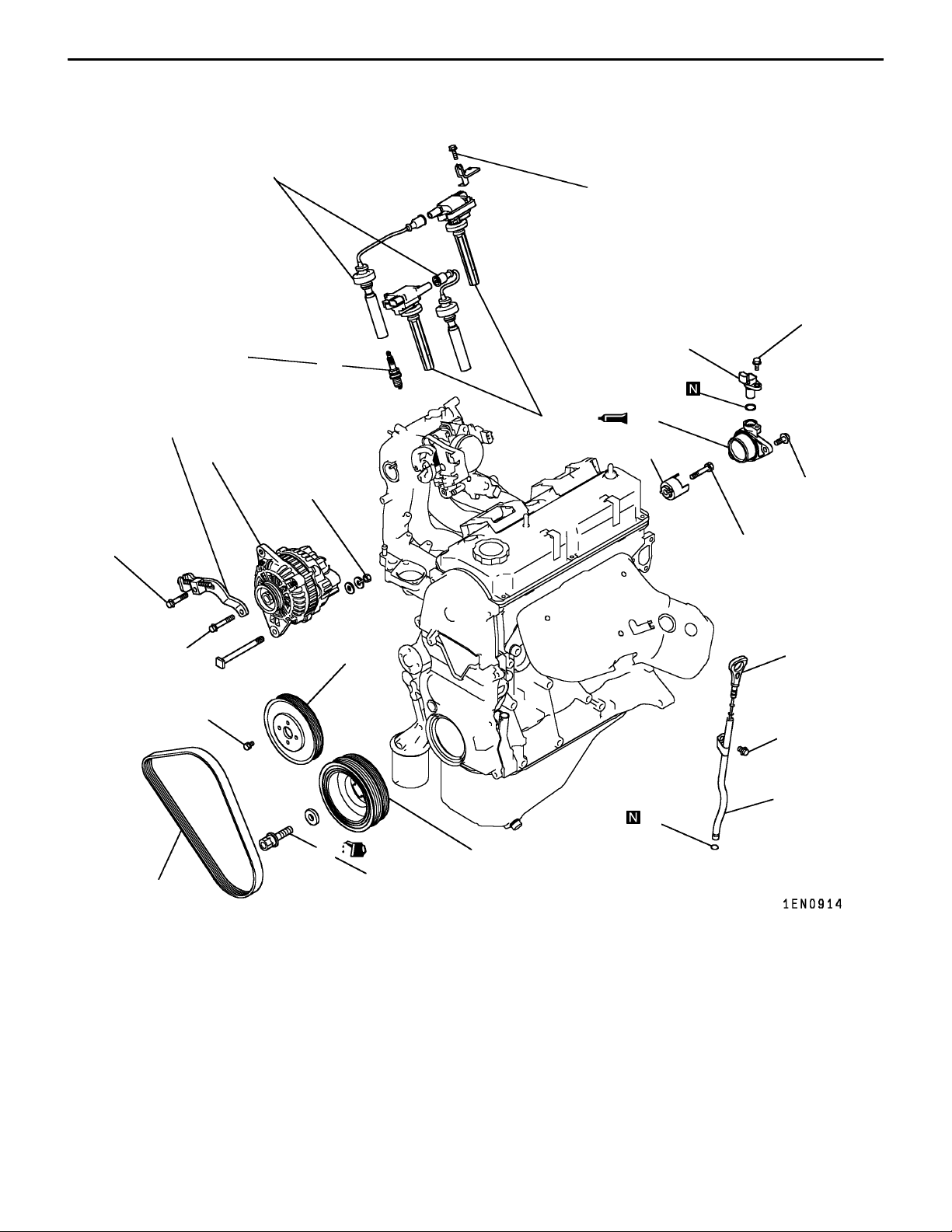
4G1 ENGINE (E–W) – Alternator and Ignition System
REMOVAL AND INSTALLATION <SOHC 16-VALVE – REAR WHEEL DRIVE>
10
10 Nm
25 Nm
12
13
9 Nm
22 Nm
6
23 Nm
4
9 Nm
11
7
44 Nm
5
14
15
13 Nm
21 Nm
1
23 Nm
2
3
8
125 Nm
9
Removal steps
1. Oil level gauge
2. Oil level gauge guide
3. O-ring
4. Drive belt*
5. Water pump pulley
6. Alternator brace
7. Alternator
AA""BA 8. Crankshaft bolt
"BA 9. Crankshaft pulley
E
E
Nov. 1995Mitsubishi Motors Corporation
Feb. 2001Mitsubishi Motors Corporation Revised
NOTE
PWEE9520
PWEE9520-E
10. Spark plug cable
11. Ignition coil
12. Spark plug
13. Cam position sensor
"CA 14. Cam position sensor support
15. Cam position sensing cylinder
*: For details of adjustment, refer to the relevant model’s
chassis workshop manual.
4G1 ENGINE (E–W) – Alternator and Ignition System
REMOVAL AND INSTALLATION <DOHC>
10
25 Nm
11
11A-3-3
12
11 Nm
13
22 Nm
23 Nm
4
6
9 Nm
7
44 Nm
5
1
23 Nm
2
3
8
125 Nm
9
Removal steps
1. Oil level gauge
2. Oil level gauge guide
3. O-ring
4. Drive belt*
5. Water pump pulley
6. Alternator brace
7. Alternator
AA""BA 8. Crankshaft bolt
"BA 9. Crankshaft pulley
E
E
Nov. 1995Mitsubishi Motors Corporation
Feb. 2001Mitsubishi Motors Corporation Revised
NOTE
PWEE9520
PWEE9520-E
10. Spark plug cable
11. Spark plug
"AA 12. Distributor
13. O-ring
*: For details of adjustment, refer to the relevant model’s
chassis workshop manual.
 Loading...