

Page 1

HARDWARE USER GUIDE
Page 2

Page 3

Table of Contents
Chapter 1 - Before You Begin
Before You Begin . . . . . . . . . . . . . . . . . . . . . . . . . . . . . . . . . . . . . . . . . . . . . . . . . . . . . . . . . . . . . 3
Printing the Hardware User Guide . . . . . . . . . . . . . . . . . . . . . . . . . . . . . . . . . . . . . . . . . . . . . 3
What's New in this Release? . . . . . . . . . . . . . . . . . . . . . . . . . . . . . . . . . . . . . . . . . . . . . . . . . 3
Disclaimer . . . . . . . . . . . . . . . . . . . . . . . . . . . . . . . . . . . . . . . . . . . . . . . . . . . . . . . . . . . . . . . 4
Trademarks . . . . . . . . . . . . . . . . . . . . . . . . . . . . . . . . . . . . . . . . . . . . . . . . . . . . . . . . . . . . . . 4
Copyright . . . . . . . . . . . . . . . . . . . . . . . . . . . . . . . . . . . . . . . . . . . . . . . . . . . . . . . . . . . . . . . . 4
Safety Instructions . . . . . . . . . . . . . . . . . . . . . . . . . . . . . . . . . . . . . . . . . . . . . . . . . . . . . . . . . 5
Chapter 2 - Specifications
Specifications . . . . . . . . . . . . . . . . . . . . . . . . . . . . . . . . . . . . . . . . . . . . . . . . . . . . . . . . . . . . . . . . 9
Technical Information . . . . . . . . . . . . . . . . . . . . . . . . . . . . . . . . . . . . . . . . . . . . . . . . . . . . . . 9
Technical Characteristics . . . . . . . . . . . . . . . . . . . . . . . . . . . . . . . . . . . . . . . . . . . . . . . . . 9
Transmission Characteristics . . . . . . . . . . . . . . . . . . . . . . . . . . . . . . . . . . . . . . . . . . . . . 11
Loss and Level Matrices . . . . . . . . . . . . . . . . . . . . . . . . . . . . . . . . . . . . . . . . . . . . . . . . . 11
Tone Plans . . . . . . . . . . . . . . . . . . . . . . . . . . . . . . . . . . . . . . . . . . . . . . . . . . . . . . . . . . . 19
E2T Compression . . . . . . . . . . . . . . . . . . . . . . . . . . . . . . . . . . . . . . . . . . . . . . . . . . . . . . 35
3300 Controller . . . . . . . . . . . . . . . . . . . . . . . . . . . . . . . . . . . . . . . . . . . . . . . . . . . . . . . . . . 38
100 Controller . . . . . . . . . . . . . . . . . . . . . . . . . . . . . . . . . . . . . . . . . . . . . . . . . . . . . . . . . 38
Mitel Networks™ 3300 - 100 Controller Components . . . . . . . . . . . . . . . . . . . . . . . . . . 38
Configurations . . . . . . . . . . . . . . . . . . . . . . . . . . . . . . . . . . . . . . . . . . . . . . . . . . . . . . . . 39
100 User System without Compression . . . . . . . . . . . . . . . . . . . . . . . . . . . . . . . . . . . . . 40
100 User System with 32 Compression Channels . . . . . . . . . . . . . . . . . . . . . . . . . . . . . 41
100 User System with 30 Voice Mail Ports . . . . . . . . . . . . . . . . . . . . . . . . . . . . . . . . . . . 42
100 User System with 32 Compression Channels and 30 Voice Mail Ports . . . . . . . . . 43
3300 Controller . . . . . . . . . . . . . . . . . . . . . . . . . . . . . . . . . . . . . . . . . . . . . . . . . . . . . . . . . . 44
250 and 700 Controller . . . . . . . . . . . . . . . . . . . . . . . . . . . . . . . . . . . . . . . . . . . . . . . . . . 44
Mitel Networks™ 3300 - 250 and 700 Controller Components . . . . . . . . . . . . . . . . . . . 44
Configurations . . . . . . . . . . . . . . . . . . . . . . . . . . . . . . . . . . . . . . . . . . . . . . . . . . . . . . . . 45
250 User System without Compression . . . . . . . . . . . . . . . . . . . . . . . . . . . . . . . . . . . . . 46
250 User System with 30 Voice Mail Ports . . . . . . . . . . . . . . . . . . . . . . . . . . . . . . . . . . . 47
250 User System with 32 Compression Channels . . . . . . . . . . . . . . . . . . . . . . . . . . . . . 48
250 User System with 32 Compression Channels and 30 Voice Mail Ports . . . . . . . . . 49
250 User System with 64 Compression Channels . . . . . . . . . . . . . . . . . . . . . . . . . . . . . 50
250 User System with 64 Compression Channels and 30 Voice Mail Ports . . . . . . . . . 51
700 User System without Compression . . . . . . . . . . . . . . . . . . . . . . . . . . . . . . . . . . . . . 52
700 User System with 32 Compression Channels . . . . . . . . . . . . . . . . . . . . . . . . . . . . . 53
700 User System with 64 Compression Channels . . . . . . . . . . . . . . . . . . . . . . . . . . . . . 54
Mitel Networks 3300 Controller Dimensions . . . . . . . . . . . . . . . . . . . . . . . . . . . . . . . . . . 55
3300 Controller Environment . . . . . . . . . . . . . . . . . . . . . . . . . . . . . . . . . . . . . . . . . . . . . 55
3300 Controller Power . . . . . . . . . . . . . . . . . . . . . . . . . . . . . . . . . . . . . . . . . . . . . . . . . . 55
3300 Controller PCB Interfaces . . . . . . . . . . . . . . . . . . . . . . . . . . . . . . . . . . . . . . . . . . . 56
Release 3.3 iii
Page 4

3300 ICP Hardware User Guide
3300 Network Services Units . . . . . . . . . . . . . . . . . . . . . . . . . . . . . . . . . . . . . . . . . . . . . . . . 57
Mitel Networks™ 3300 Universal NSU Components . . . . . . . . . . . . . . . . . . . . . . . . . . . 57
3300 Universal NSU Protocols . . . . . . . . . . . . . . . . . . . . . . . . . . . . . . . . . . . . . . . . . . . . 58
3300 Universal NSU DIP Switch Settings . . . . . . . . . . . . . . . . . . . . . . . . . . . . . . . . . . . . 58
Mitel Networks™ 3300 R2 NSU Components . . . . . . . . . . . . . . . . . . . . . . . . . . . . . . . . 59
3300 R2 NSU Protocols . . . . . . . . . . . . . . . . . . . . . . . . . . . . . . . . . . . . . . . . . . . . . . . . . 59
3300 R2 NSU DIP Switch Settings . . . . . . . . . . . . . . . . . . . . . . . . . . . . . . . . . . . . . . . . . 60
Mitel Networks™ 3300 BRI NSU Components . . . . . . . . . . . . . . . . . . . . . . . . . . . . . . . . 60
3300 BRI NSU Protocols . . . . . . . . . . . . . . . . . . . . . . . . . . . . . . . . . . . . . . . . . . . . . . . . 61
Mitel Networks 3300 NSU Dimensions . . . . . . . . . . . . . . . . . . . . . . . . . . . . . . . . . . . . . . 61
3300 NSU Environment . . . . . . . . . . . . . . . . . . . . . . . . . . . . . . . . . . . . . . . . . . . . . . . . . 61
3300 NSU Power . . . . . . . . . . . . . . . . . . . . . . . . . . . . . . . . . . . . . . . . . . . . . . . . . . . . . . 62
3300 NSU Pin Allocations . . . . . . . . . . . . . . . . . . . . . . . . . . . . . . . . . . . . . . . . . . . . . . . . 62
3300 Analog Services Units . . . . . . . . . . . . . . . . . . . . . . . . . . . . . . . . . . . . . . . . . . . . . . . . . 64
Mitel Networks™ 3300 Universal ASU Components . . . . . . . . . . . . . . . . . . . . . . . . . . . 64
Mitel Networks™ 3300 ASU Components . . . . . . . . . . . . . . . . . . . . . . . . . . . . . . . . . . . 64
3300 ASU and Universal ASU Dimensions . . . . . . . . . . . . . . . . . . . . . . . . . . . . . . . . . . 65
3300 ASU and Universal ASU Environment . . . . . . . . . . . . . . . . . . . . . . . . . . . . . . . . . . 65
3300 ASU and Universal ASU Power . . . . . . . . . . . . . . . . . . . . . . . . . . . . . . . . . . . . . . . 66
3300 ASU and Universal ASU Pin Allocations . . . . . . . . . . . . . . . . . . . . . . . . . . . . . . . . 66
ONS Line Specifications . . . . . . . . . . . . . . . . . . . . . . . . . . . . . . . . . . . . . . . . . . . . . . . . . 67
LS Trunk Specifications . . . . . . . . . . . . . . . . . . . . . . . . . . . . . . . . . . . . . . . . . . . . . . . . . 69
Music On Hold (3300 Universal ASU only) . . . . . . . . . . . . . . . . . . . . . . . . . . . . . . . . . . . 70
Paging (3300 Universal ASU only) . . . . . . . . . . . . . . . . . . . . . . . . . . . . . . . . . . . . . . . . . 71
System Fail Transfer (3300 Universal ASU only) . . . . . . . . . . . . . . . . . . . . . . . . . . . . . . 71
Peripheral Node . . . . . . . . . . . . . . . . . . . . . . . . . . . . . . . . . . . . . . . . . . . . . . . . . . . . . . . . . . 72
Peripheral Unit Components . . . . . . . . . . . . . . . . . . . . . . . . . . . . . . . . . . . . . . . . . . . . . . 72
Peripheral Unit Dimensions . . . . . . . . . . . . . . . . . . . . . . . . . . . . . . . . . . . . . . . . . . . . . . 74
Peripheral Unit Environment . . . . . . . . . . . . . . . . . . . . . . . . . . . . . . . . . . . . . . . . . . . . . . 74
Peripheral Unit Power . . . . . . . . . . . . . . . . . . . . . . . . . . . . . . . . . . . . . . . . . . . . . . . . . . . 75
Peripheral Unit Cards . . . . . . . . . . . . . . . . . . . . . . . . . . . . . . . . . . . . . . . . . . . . . . . . . . . 75
SUPERSET HUB . . . . . . . . . . . . . . . . . . . . . . . . . . . . . . . . . . . . . . . . . . . . . . . . . . . . . . . . . 86
Digital Service Unit . . . . . . . . . . . . . . . . . . . . . . . . . . . . . . . . . . . . . . . . . . . . . . . . . . . . . . . . 88
Digital Service Unit Components . . . . . . . . . . . . . . . . . . . . . . . . . . . . . . . . . . . . . . . . . . 88
Digital Service Unit Dimensions . . . . . . . . . . . . . . . . . . . . . . . . . . . . . . . . . . . . . . . . . . . 89
Digital Service Unit Environment . . . . . . . . . . . . . . . . . . . . . . . . . . . . . . . . . . . . . . . . . . 89
Digital Service Unit Power . . . . . . . . . . . . . . . . . . . . . . . . . . . . . . . . . . . . . . . . . . . . . . . 90
Digital Service Unit Cards . . . . . . . . . . . . . . . . . . . . . . . . . . . . . . . . . . . . . . . . . . . . . . . . 91
Telephone Power Options . . . . . . . . . . . . . . . . . . . . . . . . . . . . . . . . . . . . . . . . . . . . . . . . . 104
Telephone Power Sources . . . . . . . . . . . . . . . . . . . . . . . . . . . . . . . . . . . . . . . . . . . . . . 104
3300 Power Dongle (Cisco compliant) . . . . . . . . . . . . . . . . . . . . . . . . . . . . . . . . . . . . . 104
PowerDsine In-line Power Unit . . . . . . . . . . . . . . . . . . . . . . . . . . . . . . . . . . . . . . . . . . . 105
iv Release 3.3
Page 5

Table of Contents
Chapter 3 - Installing
Installing . . . . . . . . . . . . . . . . . . . . . . . . . . . . . . . . . . . . . . . . . . . . . . . . . . . . . . . . . . . . . . . . . . 111
Required Components . . . . . . . . . . . . . . . . . . . . . . . . . . . . . . . . . . . . . . . . . . . . . . . . . . . . 111
Installation Site . . . . . . . . . . . . . . . . . . . . . . . . . . . . . . . . . . . . . . . . . . . . . . . . . . . . . . . 111
Parts and Equipment . . . . . . . . . . . . . . . . . . . . . . . . . . . . . . . . . . . . . . . . . . . . . . . . . . 112
Information and Services . . . . . . . . . . . . . . . . . . . . . . . . . . . . . . . . . . . . . . . . . . . . . . . 112
Power . . . . . . . . . . . . . . . . . . . . . . . . . . . . . . . . . . . . . . . . . . . . . . . . . . . . . . . . . . . . . . 113
Uninterruptible Power Supply . . . . . . . . . . . . . . . . . . . . . . . . . . . . . . . . . . . . . . . . . . . . 113
System Installation Overview . . . . . . . . . . . . . . . . . . . . . . . . . . . . . . . . . . . . . . . . . . . . . . . 114
Installation Planner . . . . . . . . . . . . . . . . . . . . . . . . . . . . . . . . . . . . . . . . . . . . . . . . . . . . . . 114
Capacity . . . . . . . . . . . . . . . . . . . . . . . . . . . . . . . . . . . . . . . . . . . . . . . . . . . . . . . . . . . . . 117
Install the 3300 Controller . . . . . . . . . . . . . . . . . . . . . . . . . . . . . . . . . . . . . . . . . . . . . . . . . 120
Install the Hard Drive . . . . . . . . . . . . . . . . . . . . . . . . . . . . . . . . . . . . . . . . . . . . . . . . . . . . . 121
Install the System ID Module . . . . . . . . . . . . . . . . . . . . . . . . . . . . . . . . . . . . . . . . . . . . . . . 122
Install DSP Modules . . . . . . . . . . . . . . . . . . . . . . . . . . . . . . . . . . . . . . . . . . . . . . . . . . . . . 123
Configure the Controller . . . . . . . . . . . . . . . . . . . . . . . . . . . . . . . . . . . . . . . . . . . . . . . . . . . 123
Set the 3300 Controller IP Address . . . . . . . . . . . . . . . . . . . . . . . . . . . . . . . . . . . . . . . . . . 125
Install the 3300 Configuration Tool . . . . . . . . . . . . . . . . . . . . . . . . . . . . . . . . . . . . . . . . . . 126
Install and Configure the Java Plug-In . . . . . . . . . . . . . . . . . . . . . . . . . . . . . . . . . . . . . 127
Program FTP User Account and Password . . . . . . . . . . . . . . . . . . . . . . . . . . . . . . . . . 127
Assign Domain Account . . . . . . . . . . . . . . . . . . . . . . . . . . . . . . . . . . . . . . . . . . . . . . . . 128
Configure IIS 5 Settings . . . . . . . . . . . . . . . . . . . . . . . . . . . . . . . . . . . . . . . . . . . . . . . . 128
Install the 3300 Universal NSU . . . . . . . . . . . . . . . . . . . . . . . . . . . . . . . . . . . . . . . . . . . . . 129
Install the 3300 Universal NSU . . . . . . . . . . . . . . . . . . . . . . . . . . . . . . . . . . . . . . . . . . . 129
Install for PRI/Q.SIG . . . . . . . . . . . . . . . . . . . . . . . . . . . . . . . . . . . . . . . . . . . . . . . . . . . 130
Install Direct Connect Device Driver . . . . . . . . . . . . . . . . . . . . . . . . . . . . . . . . . . . . . . . 130
Driver for Windows 95 and Windows 98 . . . . . . . . . . . . . . . . . . . . . . . . . . . . . . . . . . . . 130
Driver for Windows 2000 . . . . . . . . . . . . . . . . . . . . . . . . . . . . . . . . . . . . . . . . . . . . . . . 131
Create a Dial-up Network Connection . . . . . . . . . . . . . . . . . . . . . . . . . . . . . . . . . . . . . 132
Dial-up Connection for Windows 95 or Windows 98 . . . . . . . . . . . . . . . . . . . . . . . . . . . 132
Dial-up Connection for Windows 2000 . . . . . . . . . . . . . . . . . . . . . . . . . . . . . . . . . . . . . 133
Install the 3300 R2 NSU . . . . . . . . . . . . . . . . . . . . . . . . . . . . . . . . . . . . . . . . . . . . . . . . . . 133
Connections . . . . . . . . . . . . . . . . . . . . . . . . . . . . . . . . . . . . . . . . . . . . . . . . . . . . . . . . . 134
Install the 3300 BRI NSU . . . . . . . . . . . . . . . . . . . . . . . . . . . . . . . . . . . . . . . . . . . . . . . . . . 134
Setting Up the Maintenance PC . . . . . . . . . . . . . . . . . . . . . . . . . . . . . . . . . . . . . . . . . . 135
NSU Chaining . . . . . . . . . . . . . . . . . . . . . . . . . . . . . . . . . . . . . . . . . . . . . . . . . . . . . . . . . . 135
Install the 3300 Universal ASU . . . . . . . . . . . . . . . . . . . . . . . . . . . . . . . . . . . . . . . . . . . . . 135
Install the 3300 ASU . . . . . . . . . . . . . . . . . . . . . . . . . . . . . . . . . . . . . . . . . . . . . . . . . . . . . 136
Install the Peripheral Unit . . . . . . . . . . . . . . . . . . . . . . . . . . . . . . . . . . . . . . . . . . . . . . . . . . 136
Overview of the Peripheral Unit Installation . . . . . . . . . . . . . . . . . . . . . . . . . . . . . . . . . 136
Unpack, Position, and Ground the Peripheral Unit . . . . . . . . . . . . . . . . . . . . . . . . . . . . 137
Peripheral Unit Card Layout . . . . . . . . . . . . . . . . . . . . . . . . . . . . . . . . . . . . . . . . . . . . . 137
Connect Fiber Cable to the Peripheral Unit . . . . . . . . . . . . . . . . . . . . . . . . . . . . . . . . . 138
Peripheral Unit Grounding . . . . . . . . . . . . . . . . . . . . . . . . . . . . . . . . . . . . . . . . . . . . . . 139
Power Converter . . . . . . . . . . . . . . . . . . . . . . . . . . . . . . . . . . . . . . . . . . . . . . . . . . . . . . 140
Release 3.3 v
Page 6

3300 ICP Hardware User Guide
Install Peripheral Interface Cards . . . . . . . . . . . . . . . . . . . . . . . . . . . . . . . . . . . . . . . . . 141
Cable the Unit to the MDF . . . . . . . . . . . . . . . . . . . . . . . . . . . . . . . . . . . . . . . . . . . . . . 141
Peripheral Interface Cabling Tables . . . . . . . . . . . . . . . . . . . . . . . . . . . . . . . . . . . . . . . 143
USOC Connector Pin Designations . . . . . . . . . . . . . . . . . . . . . . . . . . . . . . . . . . . . . . . 143
Card Connections to Cross-Connect Field . . . . . . . . . . . . . . . . . . . . . . . . . . . . . . . . . . 145
Card Slot 1 . . . . . . . . . . . . . . . . . . . . . . . . . . . . . . . . . . . . . . . . . . . . . . . . . . . . . . . . . . 145
Card Slot 2 . . . . . . . . . . . . . . . . . . . . . . . . . . . . . . . . . . . . . . . . . . . . . . . . . . . . . . . . . . 146
Card Slot 3 . . . . . . . . . . . . . . . . . . . . . . . . . . . . . . . . . . . . . . . . . . . . . . . . . . . . . . . . . . 147
Card Slot 4 . . . . . . . . . . . . . . . . . . . . . . . . . . . . . . . . . . . . . . . . . . . . . . . . . . . . . . . . . . 148
Card Slot 5 . . . . . . . . . . . . . . . . . . . . . . . . . . . . . . . . . . . . . . . . . . . . . . . . . . . . . . . . . . 150
Card Slot 6 . . . . . . . . . . . . . . . . . . . . . . . . . . . . . . . . . . . . . . . . . . . . . . . . . . . . . . . . . . 151
Card Slot 7 . . . . . . . . . . . . . . . . . . . . . . . . . . . . . . . . . . . . . . . . . . . . . . . . . . . . . . . . . . 152
Card Slot 8 . . . . . . . . . . . . . . . . . . . . . . . . . . . . . . . . . . . . . . . . . . . . . . . . . . . . . . . . . . 153
Card Slot 9 . . . . . . . . . . . . . . . . . . . . . . . . . . . . . . . . . . . . . . . . . . . . . . . . . . . . . . . . . . 154
Card Slot 10 . . . . . . . . . . . . . . . . . . . . . . . . . . . . . . . . . . . . . . . . . . . . . . . . . . . . . . . . . 155
Card Slot 11 . . . . . . . . . . . . . . . . . . . . . . . . . . . . . . . . . . . . . . . . . . . . . . . . . . . . . . . . . 156
Card Slot 12 . . . . . . . . . . . . . . . . . . . . . . . . . . . . . . . . . . . . . . . . . . . . . . . . . . . . . . . . . 157
Install the SUPERSET HUB . . . . . . . . . . . . . . . . . . . . . . . . . . . . . . . . . . . . . . . . . . . . . . . . 158
Overview of the SUPERSET Hub Installation . . . . . . . . . . . . . . . . . . . . . . . . . . . . . . . . 158
Install the Peripheral Slot FIM Carrier . . . . . . . . . . . . . . . . . . . . . . . . . . . . . . . . . . . . . . 158
Install the SUPERSET HUB . . . . . . . . . . . . . . . . . . . . . . . . . . . . . . . . . . . . . . . . . . . . . 159
Install the Digital Service Unit . . . . . . . . . . . . . . . . . . . . . . . . . . . . . . . . . . . . . . . . . . . . . . 160
Overview of the Digital Service Unit Installation . . . . . . . . . . . . . . . . . . . . . . . . . . . . . . 160
Unpack, Position, and Ground the DSU . . . . . . . . . . . . . . . . . . . . . . . . . . . . . . . . . . . . 160
DSU Card Layout . . . . . . . . . . . . . . . . . . . . . . . . . . . . . . . . . . . . . . . . . . . . . . . . . . . . . 161
Connect Fiber Cable to the DSU . . . . . . . . . . . . . . . . . . . . . . . . . . . . . . . . . . . . . . . . . 161
Install DSU Cards . . . . . . . . . . . . . . . . . . . . . . . . . . . . . . . . . . . . . . . . . . . . . . . . . . . . . 162
Interface Assembly . . . . . . . . . . . . . . . . . . . . . . . . . . . . . . . . . . . . . . . . . . . . . . . . . . . . 162
DS1 Interface Assembly and Cabling . . . . . . . . . . . . . . . . . . . . . . . . . . . . . . . . . . . . . . 163
CEPT Interface Assembly and Cabling . . . . . . . . . . . . . . . . . . . . . . . . . . . . . . . . . . . . 163
Install Wireless Devices . . . . . . . . . . . . . . . . . . . . . . . . . . . . . . . . . . . . . . . . . . . . . . . . . . . 164
Install Symbol NetVision MiNET Phone Administrator Tool . . . . . . . . . . . . . . . . . . . . . 164
Install 3300 ICP as a Stand-alone IP Gateway . . . . . . . . . . . . . . . . . . . . . . . . . . . . . . . . . 165
Install 3300 ICP as a Stand-alone Voice Mail . . . . . . . . . . . . . . . . . . . . . . . . . . . . . . . . . . 166
Install the 3300 In-Line Power Unit . . . . . . . . . . . . . . . . . . . . . . . . . . . . . . . . . . . . . . . . . . 166
Rack Mounting . . . . . . . . . . . . . . . . . . . . . . . . . . . . . . . . . . . . . . . . . . . . . . . . . . . . . . . 167
Shelf Mounting . . . . . . . . . . . . . . . . . . . . . . . . . . . . . . . . . . . . . . . . . . . . . . . . . . . . . . . 167
Powering Up . . . . . . . . . . . . . . . . . . . . . . . . . . . . . . . . . . . . . . . . . . . . . . . . . . . . . . . . . 167
Connecting Cables to the In-Line Power Unit . . . . . . . . . . . . . . . . . . . . . . . . . . . . . . . . 168
Connecting Cables to End Devices . . . . . . . . . . . . . . . . . . . . . . . . . . . . . . . . . . . . . . . 168
Install the 3300 In-Line Power Adapter . . . . . . . . . . . . . . . . . . . . . . . . . . . . . . . . . . . . . . . 169
Install 3300 Power Dongle (Cisco compliant) . . . . . . . . . . . . . . . . . . . . . . . . . . . . . . . . . . 169
Install 3300 Power Dongle (Cisco compliant) . . . . . . . . . . . . . . . . . . . . . . . . . . . . . . . . 169
Pre-Release 3.2 IP Phones . . . . . . . . . . . . . . . . . . . . . . . . . . . . . . . . . . . . . . . . . . . . . 170
Mixed Release 3.1 and 3.2 Network . . . . . . . . . . . . . . . . . . . . . . . . . . . . . . . . . . . . . . . 171
vi Release 3.3
Page 7

Table of Contents
Chapter 4 - Install Upgrades and FRUs
Install Upgrades and FRUs . . . . . . . . . . . . . . . . . . . . . . . . . . . . . . . . . . . . . . . . . . . . . . . . . . . 175
Hardware . . . . . . . . . . . . . . . . . . . . . . . . . . . . . . . . . . . . . . . . . . . . . . . . . . . . . . . . . . . . . . 175
Controller Upgrade Options . . . . . . . . . . . . . . . . . . . . . . . . . . . . . . . . . . . . . . . . . . . . . 175
100 User System - Add Voice Mail Ports . . . . . . . . . . . . . . . . . . . . . . . . . . . . . . . . . . . 176
100 User System - Add 32 Compression Channels . . . . . . . . . . . . . . . . . . . . . . . . . . . 177
100 User System - Add 32 Compression Channels and Voice Mail Ports . . . . . . . . . . 178
250 User System - Add Voice Mail Ports . . . . . . . . . . . . . . . . . . . . . . . . . . . . . . . . . . . 179
250 User System - Add 32 Compression Channels . . . . . . . . . . . . . . . . . . . . . . . . . . . 180
250 User System - Add 32 Compression Channels and Voice Mail Ports . . . . . . . . . . 181
250 User System - Add 64 Compression Channels . . . . . . . . . . . . . . . . . . . . . . . . . . . 183
250 User System - Add 64 Compression Channels and Voice Mail Ports . . . . . . . . . . 185
250 User to 700 User System - No Compression Channels . . . . . . . . . . . . . . . . . . . . 186
250 User to 700 User System - 32 Compression Channels . . . . . . . . . . . . . . . . . . . . . 188
250 User to 700 User System - 64 Compression Channels . . . . . . . . . . . . . . . . . . . . . 189
700 User System - Add 32 Compression Channels . . . . . . . . . . . . . . . . . . . . . . . . . . . 190
700 User System - Add 64 Compression Channels . . . . . . . . . . . . . . . . . . . . . . . . . . . 192
SX-2000 LIGHT to 3300 ICP . . . . . . . . . . . . . . . . . . . . . . . . . . . . . . . . . . . . . . . . . . . . 194
SX-2000 MICRO LIGHT to 3300 ICP . . . . . . . . . . . . . . . . . . . . . . . . . . . . . . . . . . . . . . 195
3200 ICP to 3300 ICP . . . . . . . . . . . . . . . . . . . . . . . . . . . . . . . . . . . . . . . . . . . . . . . . . . 195
Software . . . . . . . . . . . . . . . . . . . . . . . . . . . . . . . . . . . . . . . . . . . . . . . . . . . . . . . . . . . . . . . 195
Software Upgrade Procedure (3.2 to 3.3) . . . . . . . . . . . . . . . . . . . . . . . . . . . . . . . . . . . 195
Upgrade SX-2000 LIGHT to 3300 ICP Software . . . . . . . . . . . . . . . . . . . . . . . . . . . . . 202
Upgrade SX-2000 MICRO LIGHT to 3300 ICP Software . . . . . . . . . . . . . . . . . . . . . . . 203
Upgrade 3200 ICP to 3300 ICP Software . . . . . . . . . . . . . . . . . . . . . . . . . . . . . . . . . . . 204
Field Replaceable Units . . . . . . . . . . . . . . . . . . . . . . . . . . . . . . . . . . . . . . . . . . . . . . . . 208
Peripheral Node FRUs . . . . . . . . . . . . . . . . . . . . . . . . . . . . . . . . . . . . . . . . . . . . . . . . . 213
Chapter 5 - Programming
Programming . . . . . . . . . . . . . . . . . . . . . . . . . . . . . . . . . . . . . . . . . . . . . . . . . . . . . . . . . . . . . . 257
Overview of Programming . . . . . . . . . . . . . . . . . . . . . . . . . . . . . . . . . . . . . . . . . . . . . . . . . 257
Use IMAT . . . . . . . . . . . . . . . . . . . . . . . . . . . . . . . . . . . . . . . . . . . . . . . . . . . . . . . . . . . . . . 257
Chapter 6 - Troubleshooting
Troubleshooting . . . . . . . . . . . . . . . . . . . . . . . . . . . . . . . . . . . . . . . . . . . . . . . . . . . . . . . . . . . . 233
Hardware . . . . . . . . . . . . . . . . . . . . . . . . . . . . . . . . . . . . . . . . . . . . . . . . . . . . . . . . . . . . . . 233
Troubleshoot the 3300 Controller . . . . . . . . . . . . . . . . . . . . . . . . . . . . . . . . . . . . . . . . . 233
System Hardware Profile . . . . . . . . . . . . . . . . . . . . . . . . . . . . . . . . . . . . . . . . . . . . . . . 234
Troubleshoot the 3300 Universal NSU . . . . . . . . . . . . . . . . . . . . . . . . . . . . . . . . . . . . . 234
Troubleshoot the 3300 R2 NSU . . . . . . . . . . . . . . . . . . . . . . . . . . . . . . . . . . . . . . . . . . 236
Troubleshoot the 3300 BRI NSU . . . . . . . . . . . . . . . . . . . . . . . . . . . . . . . . . . . . . . . . . 237
Troubleshoot the 3300 Universal ASU . . . . . . . . . . . . . . . . . . . . . . . . . . . . . . . . . . . . . 237
Troubleshoot the 3300 ASU . . . . . . . . . . . . . . . . . . . . . . . . . . . . . . . . . . . . . . . . . . . . . 238
Troubleshoot the 3300 In-Line Power Unit . . . . . . . . . . . . . . . . . . . . . . . . . . . . . . . . . . 238
Release 3.3 vii
Page 8

3300 ICP Hardware User Guide
Troubleshooting . . . . . . . . . . . . . . . . . . . . . . . . . . . . . . . . . . . . . . . . . . . . . . . . . . . . . . . . . 239
Peripheral Unit . . . . . . . . . . . . . . . . . . . . . . . . . . . . . . . . . . . . . . . . . . . . . . . . . . . . . . . . . . 242
Troubleshoot Fiber Interface Module . . . . . . . . . . . . . . . . . . . . . . . . . . . . . . . . . . . . . . 242
Troubleshoot the DID Loop/Tie Trunk Card . . . . . . . . . . . . . . . . . . . . . . . . . . . . . . . . . 243
Troubleshoot the DNI Line Card . . . . . . . . . . . . . . . . . . . . . . . . . . . . . . . . . . . . . . . . . . 243
Troubleshoot the DTMF Receiver Card . . . . . . . . . . . . . . . . . . . . . . . . . . . . . . . . . . . . 244
Troubleshoot E&M Trunk Card . . . . . . . . . . . . . . . . . . . . . . . . . . . . . . . . . . . . . . . . . . . 244
Troubleshoot LS/GS Trunk Card . . . . . . . . . . . . . . . . . . . . . . . . . . . . . . . . . . . . . . . . . 245
Troubleshoot the ONS Line Card . . . . . . . . . . . . . . . . . . . . . . . . . . . . . . . . . . . . . . . . . 247
Troubleshoot the ONS CLASS/CLIP Card . . . . . . . . . . . . . . . . . . . . . . . . . . . . . . . . . . 247
Troubleshoot the OPS Line Card . . . . . . . . . . . . . . . . . . . . . . . . . . . . . . . . . . . . . . . . . 248
DSU Node . . . . . . . . . . . . . . . . . . . . . . . . . . . . . . . . . . . . . . . . . . . . . . . . . . . . . . . . . . . . . 248
Troubleshoot Fiber Interface Module . . . . . . . . . . . . . . . . . . . . . . . . . . . . . . . . . . . . . . 248
Troubleshoot the BRI Card . . . . . . . . . . . . . . . . . . . . . . . . . . . . . . . . . . . . . . . . . . . . . . 249
Troubleshoot the CEPT/DS1 Formatter Card . . . . . . . . . . . . . . . . . . . . . . . . . . . . . . . . 250
Troubleshoot the Conference Card . . . . . . . . . . . . . . . . . . . . . . . . . . . . . . . . . . . . . . . 250
Troubleshoot the PRI Card . . . . . . . . . . . . . . . . . . . . . . . . . . . . . . . . . . . . . . . . . . . . . . 251
Troubleshoot the R2 Card . . . . . . . . . . . . . . . . . . . . . . . . . . . . . . . . . . . . . . . . . . . . . . 252
Other . . . . . . . . . . . . . . . . . . . . . . . . . . . . . . . . . . . . . . . . . . . . . . . . . . . . . . . . . . . . . . . . . 253
Troubleshooting . . . . . . . . . . . . . . . . . . . . . . . . . . . . . . . . . . . . . . . . . . . . . . . . . . . . . . 253
viii Release 3.3
Page 9

Chapter 1
Before You Begin
Page 10

3300 ICP Hardware User Guide
2 Release 3.3
Page 11

Before You Begin
Printing the Hardware User Guide
You can access a printable version of the Hardware User Guide from the System Administration
Tool Help and from our web site.
Note: You must have Adobe Acrobat® Reader to view and print the Hardware User Guide.
If you need a copy of Adobe Acrobat Reader, it is available for download at
http://www.adobe.com/acrobat.
Go to section What's New in this Release? to find a list of changes to software and hardware
from one product version to the next.
What's New in this Release?
3300 ICP Release 3.3:
Before You Begin
• New 3300 - 100 user chassis and configurations
• Geographic expansion. See Loss Level and Tone Plans
• Updates to IP-TDM G.729 compression
• Upgrading 250/700 User systems to 30 Voice Mail ports
• New Software Upgrade procedure.
3300 ICP Release 3.2:
• Single software build: select your country to set the appropriate language, dialing plan,
tone plan, and loss & level plan.
• IP-TDM (E2T) G.729 compression
• Optimized system performance: 300 MHz E2T and RTC
• Symbol wireless telephones
• 3300 ICP as a Stand-alone Wireless Gateway
• 3300 ICP as a Stand-alone Voice Mail
• Range programming to simplify the addition, change, or deletion of repetitive or
incremental values
• Telephone power options
• Personal and Corporate Directories on the 5140 IP Appliance
• System Hardware Profile to view information about installed hardware
• Controller upgrade options for capacity, version, and/or compression
• ASU and Universal ASU to support the European market
Release 3.3 3
Page 12

3300 ICP Hardware User Guide
3300 ICP Release 3.1:
• Migration of SX-2000
• Migration of SX-2000 MICRO LIGHT to 3300 ICP
• Migration of 3200 ICP to 3300 ICP
• Peripheral Node support
• Digital Service Unit support
• NSU Chaining
• 5001 IP Phone and 5005 IP Phone
•Security
Disclaimer
The information contained in this document is believed to be accurate in all respects but is not
warranted by Mitel Networks Corporation (MITEL®). The information is subject to change
without notice and should not be construed in any way as a commitment by Mitel or any of its
affiliates or subsidiaries. Mitel and its affiliates and subsidiaries assume no responsibility for
any errors or omissions in this document. Revisions of this document or new editions of it may
be issued to incorporate such changes.
®
LIGHT to 3300 ICP
Trademarks
Mitel Networks, MiTAI, SUPERSET, SX-2000 are trademarks of Mitel Networks Corporation.
Windows and Microsoft are trademarks of Microsoft Corporation.
Java is a trademark of Sun Microsystems Incorporated.
Adobe Acrobat Reader is a registered trademark of Adobe Systems Incorporated.
Other product names mentioned in this document may be trademarks of their respective
companies and are hereby acknowledged.
Copyright
®,™ Trademark of MITEL Networks Corporation
© Copyright 2002, MITEL Networks Corporation
All rights reserved
4 Release 3.3
Page 13

Safety Instructions
You can access a printable version of the Safety Instructions from our edocs web site.
Note: You must have Adobe Acrobat® Reader to view and print the Safety Instructions.
If you need a copy of Adobe Acrobat
http://www.adobe.com/acrobat
Before You Begin
®
Reader, it is available for download at
.
Release 3.3 5
Page 14

3300 ICP Hardware User Guide
6 Release 3.3
Page 15

Chapter 2
Specifications
Page 16

3300 ICP Hardware User Guide
8 Release 3.3
Page 17

Specifications
Technical Information
Technical Characteristics
Signaling and Supervisory Tones
The standard range of programmed tones are composed of
• 12 DTMF sets of tones
• 1 set of tones that form part of the call progress tone plan
• 1 test of 1004 Hz (digital milliwatt).
DTMF Signaling
Input Signaling: The system is capable of accepting and repeating the standard DTMF tones
as specified in EIA/TIA 464-C.
Specifications
Output Signaling: The Mitel Networks 3300 ICP meets the output signaling requirements as
specified in EIA/TIA 464-C.
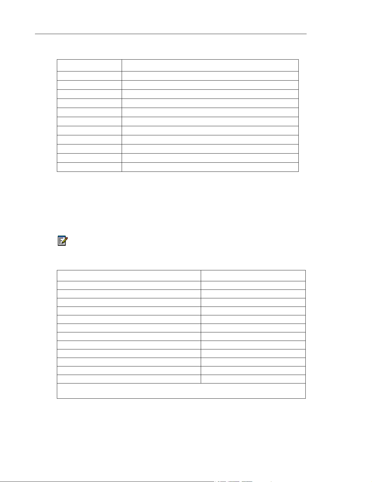
DTMF Output Signaling as specified by EIA/TIA 464-C
frequency deviation 1 percent
tone duration greater than 40 ms
interdigit time greater than 40 ms
level, low group greater than -10 dbm
level, high group greater than -8 dbm
level, low group and high group combined less than +2 db
level, third greater than 40 db
frequency below dtmf signal
twist less than 4 db
Time-Out Information
The system is capable of responding to, or providing, the following supervisory conditions:
• Switchhook flashes having a duration of between 160 ms and 1500 ms (as programmed)
to activate Transfer/Consultation/Hold/Add-On features.
• Call transfer dial tone can be obtained by generating a calibrated flash. This method is
recognized internationally and is generated in one of three ways:
- use a flash-hook for telephones connected to ONS circuits. Upper and lower detection
thresholds for switchhook flash are programmable between 60 ms and 500 ms, and
between 60 ms and 1500 ms respectively.
- use the calibrated flash button (for equipped telephones)
Release 3.3 9
Page 18

3300 ICP Hardware User Guide
- dial the digit ‘1’ on an ordinary rotary telephone.
• Station switchhook flashes of less than the maximum programmed switchhook flash time
will not be repeated towards the central office.
• An open Tip lead condition of 500 ms (optional 100 ms) or more duration on a CO trunk
will release the system connection.
• Momentary open loop conditions of up to 350 ms (optional 100 ms) generated by the
central office on outgoing system calls will not release calls.
• Station on-hook conditions will release a trunk connection after the selected maximum
time.
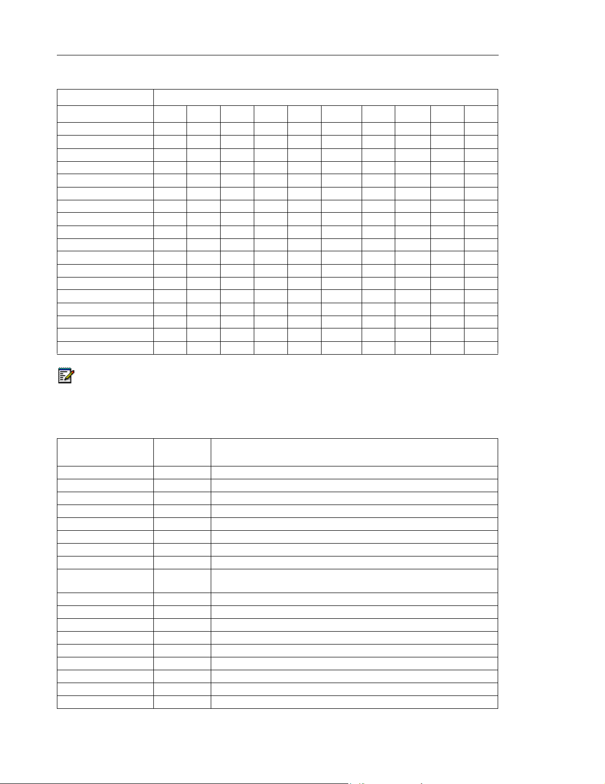
Feature Time-Out Period Description
No Answer Recall
Timer
Camp-On Recall Timer 0 - 180 s Incoming calls camped-on to a busy station
Call Hold Timer 10 - 600 s Calls placed on hold ring back to the station user
Attendant Busyout
Timer
First Digit Timer 5 - 60 s This is the time the system will wait for the first
Interdigit Timer 3 - 60 s Time between dialed digits.
Delay Ring Timer 5 - 60 s Time before line rings on key set.
Callback Cancel Timer 1 - 24 hrs Time after which callback functions are reset and
Call Forward - No
Answer Timer
Switchhook Flash 60 - 1500 ms Length of time that a switchhook can be flashed
Ringing Timer 60 - 300 s The length of time a station rings another station
Time-Out Information
0 - 125 s If there is no answer at the extension after
time-out expires, it will ringback at the attendant
console or transfer station.
before being returned to the attendant, if not
answered before time-out expires.
upon expiry.
1 - 1440 min System switches to night service if there is no
activity at the attendant console after calls are
received.
digit after going offhook at a station.
cleared, or cancelled.
0 - 125 s Length of time a station rings before the call is
forwarded or rerouted.
without dropping the trunk or line.
before the call is terminated.
Line and Trunk Support Characteristics (NA)
The North American variant of the system supports the following line and trunk parameters:
• Station Loop - The industry standard station loop range, including the station apparatus,
can be up to a maximum of 600 ohms (ONS Line).
• DNI Device Ranges - Any device which interfaces to a DNI line card has a loop length of
2 kilometers (6600 ft) with 24 (0.6mm) or 26 (0.45mm) AWG twisted pair cable with no
bridge taps, and one kilometre with a maximum of one bridge tap of any length. A maximum
of 50 m (162.5 ft) of 22 AWG (0.7mm) quad cable may also be used.
10 Release 3.3
Page 19

Specifications
• CO Trunk Loop - The system operates with CO Trunks up to a maximum of 1600 ohms
loop resistance.
• CO Trunk Seizure - The nominal seizure resistance is 265 ohms at 20 mA.
• CO Trunk Resistance - The on-hook dc input resistance of the LS trunks is not less than
5M ohms.
Transmission Characteristics
Compliance
The transmission characteristics for the North American and Latin American variants comply
with:
• ANSI/EIA/TIA 464-C 'Requirements for Private Branch Exchange (PBX) Switching
Equipment'.
• TIA-912 'Voice Gateway Transmission Requirements'.
The transmission characteristics for the United Kingdom variants comply with:
• ETSI ES 202 020 'Harmonized Pan-European/North American loss and level plan for voice
gateways to IP based networks'.
Mitel Networks digital telephones meet the requirements of:
• ANSI/TIA/EIA-810-A 'Transmission Requirements for Narrowband Voice over IP and Voice
over PCM Digital Wireline Telephones'.
Loss and Level Matrices
Requirements Specifications
Each country has stipulated requirements concerning acceptable transmission performance
for telephone systems. The loss plan matrices provide the correct electrical losses in decibels
(dB) for each connection to meet the specified requirement.
Loss plans have a direct effect on the acoustic levels provided at the set. Part of meeting the
requirements is to identify the reference set requirements for all standard and proprietary sets
to be used in each country. It is generally desirable to achieve the same relative loudness levels
for all standard and proprietary telephones for a specified loss plan, taking into account loop
lengths, transmission format (analog or digital), different transducers in use, line/trunk
impedances, and terminating impedances.
Release 3.3 11
Page 20
3300 ICP Hardware User Guide
Loss and Level Requirements Specifications
Country Requirement Document
Australia ACIF S002, S003
Canada CS03, T520, T512
France TBR21, ST13
Germany TBR21
Italy TBR21
Netherlands TBR21
New Zealand TNA-102, PTC-207, PTC-217
North America TIA/EIA 464-C, TIA/EIA TSB 116
Portugal TBR21
Spain TBR21
United Kingdom BTR1050, BTR1080, BTR 1181, NCOP(86)42 and BS6450 Pt 4
Implementation
In the loss plans, positive values are losses and negative values are gains. The losses are
shown in one direction only (outgoing, from the specified port type); the reverse path loss can
be found by using a second look up (e.g. In North America, OPS to WAN is a -3dB gain and
WAN to OPS is a 9dB loss).
Note: Mitel Networks digital telephones meet the following ITU-T recommended loudness rating:
- Send Loudness Rating (SLR) 8 dB - Receive Loudness Rating (RLR) 2 dB.
In interpreting loss plans, refer to the following legend:
Port Abbreviation
IP On Premise Station iONS
On Premise Station ONS
IP Off Premise Station iOPS
Off Premise Station OPS
Digital Station DGS
Wide Area Network WAN
Digital CO Trunk DCO
IP Analog CO Trunk iACO
IP Analog CO Trunk (short) iACOs
Analog CO Trunk ACO
Analog CO Trunk (short) ACOs
Analog Tie Trunk ATT
Note: iONS, iACO, and iACOs apply to the new analog interface designs that comply with the IP
connected half-channel loss plan. The first instances of these is on the 3300 ASU.
12 Release 3.3
Page 21

Australia
Specifications
Loss Plan Matrix
iONS →
ONS →
iOPS →
OPS →
DGS →
WAN →
DCO →
iACO →
iACOs →
ACO →
ACOs →
ATT →
Brazil
iONS →
ONS →
iOPS →
OPS →
DGS →
WAN →
DCO →
iACO →
iACOs →
ACO →
ACOs →
ATT →
iONS
ONS
↑
11 11 8 8 3 3 2 0 1 1 1 2
11 11 8 8 3 3 2 0 1 1 1 2
8 8 5 5 0 0 -1 -2 -2 -1 -1 -1
8 8 5 5 0 0 -1 -2 -2 -1 -1 -1
8 8 5 5 0 0 0 -1 2 0 3 0
8 8 5 5 0 0 0 -1 2 0 3 0
8 8 5 5 0 0 0 -1 0 0 0 0
0 0 -3 -3 -6 -5 -6 -4 -4 -4 -4 -6
1 1 -2 -2 -6 -6 -6 -4 -4 -4 -4 -6
0 0 -3 -3 -6 -6 -6 -4 -4 -4 -4 -6
1 1 -2 -2 -6 -6 -6 -4 -4 -4 -4 -6
7 7 4 4 0 0 0 0 0 0 0 0
iOPS
↑
OPS↑DGS↑WAN ↑DCO ↑iACO ↑iACOs ↑ACO ↑ACOs ↑ATT
↑
Loss Plan Matrix
iONS
ONS
↑
6 6 3 3 0 0 3 0 3 0 3 3
6 6 3 3 0 0 3 0 3 0 3 3
3 3 0 0 -3 -3 0 0 0 0 0 3
3 3 0 0 -3 -3 0 0 0 0 0 3
9 9 6 6 0 0 0 2 3 0 3 3
9 9 6 6 0 0 0 3 0 3 0 3
9 9 6 6 0 0 0 3 0 3 0 3
0 0 0 0 -9 -6 -3 0 0 0 0 0
3 3 0 0 -6 -3 -3 0 0 0 0 0
0 0 0 0 -9 -3 -3 0 0 0 0 0
3 3 0 0 -6 0 0 0 0 0 0 0
3 3 0 0 -3 -3 -3 0 0 0 0 0
iOPS
↑
OPS↑DGS↑WAN ↑DCO ↑iACO ↑iACOs ↑ACO ↑ACOs ↑ATT
↑
↑
↑
Release 3.3 13
Page 22

3300 ICP Hardware User Guide
France
Loss Plan Matrix
iONS →
ONS →
iOPS →
OPS →
DGS →
WAN →
DCO →
iACO →
iACOs →
ACO →
ACOs →
ATT →
iONS
ONS
↑
15 15 12 12 5 5 4 2 5 2 5 5
15 15 12 10 3 3 3 1 4 1 4 4
12 12 9 9 2 2 1 -1 2 -1 2 2
12 12 9 7 0 0 0 -2 1 -2 1 1
10 10 7 7 0 0 0 0 2 0 2 4
10 10 7 7 0 0 0 0 2 0 2 4
11 11 8 7 0 0 0 0 2 0 2 4
1 1 -2 -2 -6 -6 -6 -6 -4 -6 -4 -2
4 4 1 1 -3 -3 -3 -4 -2 -4 -2 1
1 1 -2 -2 -6 -6 -6 -6 -4 -6 -4 -2
2 2 -1 -1 -5 -5 -5 -5 -3 -5 -3 -1
4 4 1 1 -3 -3 -3 -2 1 -2 1 1
iOPS
↑
OPS↑DGS↑WAN ↑DCO ↑iACO ↑iACOs ↑ACO ↑ACOs ↑ATT
↑
↑
14 Release 3.3
Page 23

Germany
Specifications
Loss Plan Matrix
iONS
ONS
iOPS
OPS
DGS
WAN
DCO
iACO
iACOs
ACO
ACOs
ATT
iONS
→
→
→
→
→
→
→
→
→
→
→
→
ONS
↑
13 13 10 10 4 4 4 2 2 3 3 3
13 13 10 10 3 3 3 0 2 1 3 3
10 10 7 7 1 1 1 -1 -1 0 0 0
10 10 7 7 0 0 0 -1 1 0 0 0
10 10 7 7 0 0 0 -1 1 0 0 0
10 10 7 7 0 0 0 -1 1 0 0 0
10 10 7 7 0 0 0 -1 1 0 2 1
2 2 -1 0 -6 -6 -6 -7 -5 -6 -6 -6
4 4 1 1 -6 -6 -6 -7 -5 -6 -6 -6
2 2 -1 0 -6 -6 -6 -7 -5 -6 -6 -6
4 4 1 1 -6 -6 -6 -7 -5 -6 -4 -5
8 8 5 5 -2 -2 -2 -3 -1 -2 0 -1
iOPS
↑
OPS↑DGS↑WAN ↑DCO ↑iACO ↑iACOs ↑ACO ↑ACOs ↑ATT
↑
↑
iONS
ONS
iOPS
OPS
DGS
WAN
DCO
iACO
iACOs
ACO
ACOs
ATT
Italy
→
→
→
→
→
→
→
→
→
→
→
→
Loss Plan Matrix
iONS
ONS
↑
19 17 16 16 7 7 7 6 6 6 6 5
17 13 14 12 3 3 3 6 6 6 6 7
16 14 13 13 4 4 4 3 3 3 3 6
16 12 13 11 2 2 2 1 3 3 3 6
12 10 7 9 0 0 0 -1 -1 -1 -1 2
12 10 7 9 0 0 0 -1 -1 -1 -1 2
14 10 10 9 0 0 0 -1 2 2 2 4
4 4 -1 1 -6 -6 -6 -7 -7 -7 -7 -4
4 4 1 1 -6 -6 -6 -7 -7 -7 -7 -4
5 4 2 1 -2 -2 -2 -3 -3 -5 -5 -4
5 4 2 1 -2 -2 -2 -3 -3 -5 -5 -4
10 10 7 7 0 0 0 -1 -1 -1 -1 2
iOPS
↑
OPS↑DGS↑WAN ↑DCO ↑iACO ↑iACOs ↑ACO ↑ACOs ↑ATT
↑
↑
Release 3.3 15
Page 24

3300 ICP Hardware User Guide
Latin America
Loss Plan Matrix
iONS
ONS
iOPS
OPS
DGS
WAN
DCO
iACO
iACOs
ACO
ACOs
ATT
iONS
→
→
→
→
→
→
→
→
→
→
→
→
ONS
↑
6 6 3 3 0 0 3 0 3 0 3 3
6 6 3 3 0 0 3 0 3 0 3 3
3 3 0 0 -3 -3 0 0 0 0 0 3
3 3 0 0 -3 -3 0 0 0 0 0 3
9 9 6 6 0 0 0 2 3 0 3 3
9 9 6 6 0 0 0 3 0 3 0 3
9 9 6 6 0 0 0 3 0 3 0 3
0 0 0 0 -9 -6 -3 0 0 0 0 0
3 3 0 0 -6 -3 -3 0 0 0 0 0
0 0 0 0 -9 -3 -3 0 0 0 0 0
3 3 0 0 -6 0 0 0 0 0 0 0
3 3 0 0 -3 -3 -3 0 0 0 0 0
iOPS
↑
OPS↑DGS↑WAN ↑DCO ↑iACO ↑iACOs ↑ACO ↑ACOs ↑ATT
↑
↑
iONS
ONS
iOPS
OPS
DGS
WAN
DCO
iACO
iACOs
ACO
ACOs
ATT
Netherlands
→
→
→
→
→
→
→
→
→
→
→
→
Loss Plan Matrix
iONS
ONS
↑
10 10 7 7 1 1 1 1 1 1 1 1
10 10 7 7 3 3 3 2 3 3 3 3
7 7 4 4 -2 -2 -2 -2 -2 -2 -2 -2
7 7 4 4 0 0 0 -1 0 0 0 0
7 7 4 4 0 0 0 -1 0 0 0 0
7 7 4 4 0 0 0 -1 0 0 0 0
7 7 4 4 0 0 0 -1 0 0 0 0
1 1 -2 -2 -6 -6 -6 -7 -6 -6 -6 -6
1 1 -2 -2 -6 -6 -6 -7 -5 -6 -6 -5
1 1 -2 -2 -6 -6 -6 -7 -6 -6 -6 -6
1 1 -2 -2 -6 -6 -6 -7 -6 -6 -6 -5
5 5 2 2 -2 -2 -2 -2 0 -2 -2 0
iOPS
↑
OPS↑DGS↑WAN ↑DCO ↑iACO ↑iACOs ↑ACO ↑ACOs ↑ATT
↑
↑
16 Release 3.3
Page 25

New Zealand
Specifications
Loss Plan Matrix
iONS
ONS
iOPS
OPS
DGS
WAN
DCO
iACO
iACOs
ACO
ACOs
ATT
iONS
→
→
→
→
→
→
→
→
→
→
→
→
ONS
↑
11 11 8 8 3 3 3 0 2 0 2 -1
11 11 8 8 3 3 3 0 2 0 2 -1
8 8 5 5 0 0 0 -3 -1 -3 -1 -4
8 8 5 5 0 0 0 -3 -1 -3 -1 -4
8 8 5 5 0 0 0 -2 0 -2 0 -2
8 8 5 5 0 0 0 -2 0 -2 0 -2
8 8 5 5 0 0 0 -2 0 -2 0 -1
0 0 -3 -3 -8 -8 -8 -8 -8 -8 -8 -9
2 2 -1 -1 -6 -6 -6 -8 -6 -8 -6 -8
0 0 -3 -1 -3 -3 -3 -5 -5 -6 -6 -6
2 2 -1 -1 -3 -3 -3 -5 -5 -6 -6 -6
10 10 7 7 4 4 4 2 3 5 5 2
iOPS
↑
OPS↑DGS↑WAN ↑DCO ↑iACO ↑iACOs ↑ACO ↑ACOs ↑ATT
↑
↑
North America
iONS →
ONS →
iOPS →
OPS →
DGS →
WAN →
DCO →
iACO →
iACOs →
ACO →
ACOs →
ATT →
Loss Plan Matrix
iONS
ONS
↑
6 6 3 3 0 0 3 0 3 0 3 3
6 6 3 3 0 0 3 0 3 0 3 3
3 3 0 0 -3 -3 0 0 0 0 0 3
3 3 0 0 -3 -3 0 0 0 0 0 3
9 9 6 6 0 0 0 2 3 0 3 3
9 9 6 6 0 0 0 3 0 3 0 3
9 9 6 6 0 0 0 3 0 3 0 3
0 0 0 0 -9 -6 -3 0 0 0 0 0
3 3 0 0 -6 -3 -3 0 0 0 0 0
0 0 0 0 -9 -3 -3 0 0 0 0 0
3 3 0 0 -6 0 0 0 0 0 0 0
3 3 0 0 -3 -3 -3 0 0 0 0 0
iOPS
↑
OPS↑DGS↑WAN ↑DCO ↑iACO ↑iACOs ↑ACO ↑ACOs ↑ATT
↑
↑
Release 3.3 17
Page 26

3300 ICP Hardware User Guide
Portugal
Loss Plan Matrix
iONS →
ONS →
iOPS →
OPS →
DGS →
WAN →
DCO →
iACO →
iACOs →
ACO →
ACOs →
ATT →
iONS
ONS
↑
15 15 12 12 5 5 5 2 4 3 5 5
13 13 10 10 3 3 3 2 4 3 5 5
12 12 9 9 2 2 2 -1 1 0 2 2
10 10 7 7 0 0 0 -1 1 0 2 2
10 10 7 7 0 0 0 -1 1 0 0 0
10 10 7 7 0 0 0 -1 1 0 0 0
10 10 7 7 0 0 0 -1 1 0 2 1
2 2 -1 0 -6 -6 -6 -7 -5 -6 -6 -6
4 4 1 1 -6 -6 -6 -7 -5 -6 -6 -6
2 2 -1 0 -6 -6 -6 -7 -5 -6 -6 -6
4 4 1 1 -6 -6 -6 -7 -5 -6 -4 -4
6 6 3 3 -4 -4 -4 -5 -3 -4 -2 -2
iOPS
↑
OPS↑DGS↑WAN ↑DCO ↑iACO ↑iACOs ↑ACO ↑ACOs ↑ATT
↑
↑
Spain
iONS →
ONS →
iOPS →
OPS →
DGS →
WAN →
DCO →
iACO →
iACOs →
ACO →
ACOs →
ATT →
Loss Plan Matrix
iONS
ONS
↑
15 15 12 12 5 5 5 2 4 3 5 5
13 13 10 10 3 3 3 2 4 3 5 5
12 12 9 9 2 2 2 -1 1 0 2 2
10 10 7 7 0 0 0 -1 1 0 2 2
10 10 7 7 0 0 0 -1 1 0 0 0
10 10 7 7 0 0 0 -1 1 0 0 0
10 10 7 7 0 0 0 -1 1 0 2 1
2 2 -1 0 -6 -6 -6 -7 -5 -6 -6 -6
4 4 1 1 -6 -6 -6 -7 -5 -6 -6 -6
2 2 -1 0 -6 -6 -6 -7 -5 -6 -6 -6
4 4 1 1 -6 -6 -6 -7 -5 -6 -4 -4
6 6 3 3 -4 -4 -4 -5 -3 -4 -2 -2
iOPS
↑
OPS↑DGS↑WAN ↑DCO ↑iACO ↑iACOs ↑ACO ↑ACOs ↑ATT
↑
↑
18 Release 3.3
Page 27

United Kingdom
Specifications
Loss Plan Matrix
iONS
ONS
iOPS
OPS
DGS
WAN
DCO
iACO
iACOs
ACO
ACOs
ATT
iONS
→
→
→
→
→
→
→
→
→
→
→
→
ONS
↑
11 11 11 11 5 5 5 3 6 3 6 6
11 11 11 11 5 5 5 3 6 3 6 6
8 6 6 6 0 2 2 0 1 0 1 2
8 6 6 6 0 2 1 0 1 0 1 2
7 4 7 7 0 0 0 1 -2 -3 -2 0
7 7 7 7 0 0 0 1 4 4 4 4
7 7 7 7 0 0 0 1 1 4 1 4
3 3 1 1 -4 -4 -2 0 1 1 1 2
2 2 1 1 1 0 -3 3 1 1 1 4
0 -2 1 1 -1 -3 -2 0 1 1 1 4
2 2 1 1 1 0 -3 3 1 1 1 4
2 2 2 2 -2 -2 1 0 4 4 4 4
iOPS
↑
OPS↑DGS↑WAN ↑DCO ↑iACO ↑iACOs ↑ACO ↑ACOs ↑ATT
↑
↑
Tone Plans
Tone plans permit the station user to distinguish different stages of call progress and different
types of calls. Each tone is assigned a level which ensures an acceptable quality.
Australia
Ton e P l a n
Tone
ARS 2nd Dial 400/425 Continuous
Busy 425 0.375 on, 0.375 off, repeat
Camp-on 425 0.25 on, off
Conference 425 0.8 on, off
Confirmation 400/425 0.1 on, 0.1 off, 0.1 on, 0.7 off, repeat
Dial Tone 400/425 Continuous
Feature Active Dial 400/425 (0.95 on, 0.05 off) x 2, then (0.1 on, 0.1 off, 0.1 on, 0.7 off, repeat forever)
Interrupted Dial 400/425 (0.95 on, 0.05 off) x 2, then (0.1 on, 0.1 off, 0.1 on, 0.7 off, repeat forever)
Message Notification 400/425 (0.95 on, 0.05 off) x 2, then (0.1 on, 0.1 off, 0.1 on, 0.7 off, repeat forever)
Modem Answer 2025 0.95 on, 0.05 off, repeat
Override 1400 0.2 on, off
Paging 425 0.25 on, off
Reorder 425 2.5 on, 0.5 off, repeat
Ringback 400/450 0.4 on, 0.2 off, 0.4 on, 2 off, repeat
Special Busy 425 0.375 on, 0.375 off, repeat
Special Ringback 400/450 1.0 on, 2.0 off, repeat
Transfer Dial 400/425 (0.1 on, 0.1 off) x 3, then continuous
Voice Mail 440 0.6 on, off
Frequency
(Hz)
Cadence (s)
Release 3.3 19
Page 28
3300 ICP Hardware User Guide
Tone Output Level
iONS ONS iOPS OPS iACO iACOs ACO ACOs DCO ATT
ARS 2nd Dial -15 -15 --- --- -10 -13 -10 -10 -8 -12
Busy -15 -15 --- --- -10 -13 -10 -10 -8 -12
Dial -15 -15 --- --- -10 -13 -10 -10 -8 -12
Camp-on -15 -15 --- --- -10 -13 -10 -10 -8 -12
Conference -15 -15 --- --- -10 -13 -10 -10 -8 -12
Confirmation -15 -15 --- --- -10 -13 -10 -10 -8 -12
Feature Active Dial -15 -15 --- --- -10 -13 -10 -10 -8 -12
Interrupted Dial -15 -15 --- --- -10 -13 -10 -10 -8 -12
Message Notification -15 -15 --- --- -10 -13 -10 -10 -8 -12
Modem Answer -24 -24 --- --- -19 -22 -19 -19 -17 -21
Override -27 -27 --- --- -22 -25 -22 -22 -20 -24
Paging -21 -21 --- --- -16 -19 -16 -16 -14 -18
Reorder -15 -15 --- --- -10 -13 -10 -10 -8 -12
Ringback -15 -15 --- --- -10 -13 -10 -10 -8 -12
Special Busy -15 -15 --- --- -10 -13 -10 -10 -8 -12
Special Ringback -15 -15 --- --- -10 -13 -10 -10 -8 -12
Transfer Dial -15 -15 --- --- -10 -13 -10 -10 -8 -12
Voice Mail -21 -21 --- --- -16 -19 -12 -12 -14 -18
Note: DTMF tones are supported.
Note: Digital (DGS) and IP (WAN) tones are conveyed as Real-Time Transfer Protocol (RTP) packets.
Note: "---" indicates that this interface is not supported in this country.
Brazil
Ton e P l a n
Tone
ARS 2nd Dial 425 Continuous
Busy 425 0.25 on, 0.25 off, repeat
Camp-on 440 (0.1 on, 0.05 off) x 2
Conference 440 1 on, off
Confirmation 425 Continuous
Dial Tone 425 Continuous
Feature Active Dial 425 (0.1 on, 0.1 off) x 8, then continuous
Interrupted Dial 425 (0.1 on, 0.1 off) x 8, then continuous
Message Notification 425, 440, 425 425 (0.2 on, 0.2 off) x 4, then 440 (0.2 on, 0.2 off) x 2, then 425 (0.1 on,
Modem Answer 2025 0.95 on, 0.05 off, repeat
Override 440 0.8 on, off
Paging 440 0.2 on, off
Reorder 425 0.25 on, 0.25 off, 0.75 on, 0.25 off, repeat
Ringback 425 1 on, 4 off, repeat
Special Busy 425 0.5 on, 0.5 off, repeat
Special Ringback 425 0.5 on, 0.5 off, 0.5 on, 2.5 off, repeat
Transfer Dial 425 (0.1 on, 0.1 off) x 3, then continuous
Voice Mail 440 0.6 on, off
Frequency
(Hz)
Cadence (s)
0.1 off) x 4, then 425 continuous
20 Release 3.3
Page 29

Specifications
Tone Output Level
iONS ONS iOPS OPS iACO iACOs ACO ACOs DCO ATT
ARS 2nd Dial -23 -23 --- -20 -20 -20 -20 -20 -20 -20
Busy -23 -23 --- -20 -20 -20 -20 -20 -20 -20
Dial -23 -23 --- -20 -20 -20 -20 -20 -20 -20
Camp-on -17 -17 --- -14 -14 -14 -14 -14 -14 -14
Conference -19 -19 --- -16 -16 -16 -16 -16 -16 -16
Confirmation -23 -23 --- -20 -20 -20 -20 -20 -20 -20
Feature Active Dial -23 -23 --- -20 -20 -20 -20 -20 -20 -20
Interrupted Dial -23 -23 --- -20 -20 -20 -20 -20 -20 -20
Message Notification -23,
-17,
-23
Modem Answer -20 -20 --- -17 -17 -17 -17 -17 -17 -17
Override -17 -17 --- -14 -14 -14 -14 -14 -14 -14
Paging -17 -17 --- -14 -14 -14 -14 -14 -14 -14
Reorder -23 -23 --- -20 -20 -20 -20 -20 -20 -20
Ringback -23 -23 --- -20 -20 -20 -20 -20 -20 -20
Special Busy -23 -23 --- -20 -20 -20 -20 -20 -20 -20
Special Ringback -23 -23 --- -20 -20 -20 -20 -20 -20 -20
Transfer Dial -23 -23 --- -20 -20 -20 -20 -20 -20 -20
Voice Mail -17 -17 --- -14 -14 -14 -14 -14 -14 -14
-23,
-17,
-23
--- -20,
-14,
-20
-20,
-14,
-20
-20,
-14,
-20
-20,
-14,
-20
-20,
-14,
-20
-20,
-14,
-20
-20,
-14,
-20
Note: DTMF tones are supported.
Note: Digital (DGS) and IP (WAN) tones are conveyed as Real-Time Transfer Protocol (RTP) packets.
Note: "---" indicates that this interface is not supported in this country.
Release 3.3 21
Page 30

3300 ICP Hardware User Guide
France
Ton e P l a n
Tone
ARS 2nd Dial 440 Continuous
Busy 440 0.5 on, 0.5 off, repeat
Camp-on 520 0.2 on, off
Conference 400 0.6 on, off
Confirmation 440 Continuous
Dial Tone 440 Continuous
Feature Active Dial 440 0.75 on, 0.75 off, then continuous
Interrupted Dial 440 0.75 on, 0.75 off, then continuous
Message Notification 440, 520, 440 440 (0.75 on, 0.75 off) x 2, then 520 (0.2 on, 0.75 off) x 1, then 440 (0.75
Modem Answer 2025 0.95 on, 0.05 off, repeat
Override 1400 0.3 on, off
Paging 440 0.2 on, off
Reorder 440 0.5 on, 0.5 off, repeat
Ringback 440 1.5 on, 3.5 off, repeat
Special Busy 440 0.35 on, 0.35 off, repeat
Special Ringback 440 0.4 on, 0.2 off, 0.4 on, 2.0 off, repeat
Transfer Dial 440 (0.1 on, 0.1 off) x 3, then continuous
Voice Mail 440 0.6 on, off
Frequency
(Hz)
Cadence (s)
on, 0.75 off, repeat forever)
Tone Output Level
iONS ONS iOPS OPS iACO iACOs ACO ACOs DCO ATT
ARS 2nd Dial -20 -20 --- --- -15 -18 -15 -15 -13 -17
Busy -20 -20 --- --- -15 -18 -15 -15 -13 -17
Dial -20 -20 --- --- -15 -18 -15 -15 -13 -17
Camp-on -20 -20 --- --- -15 -18 -15 -15 -13 -17
Conference -20 -20 --- --- -15 -18 -15 -15 -13 -17
Confirmation -20 -20 --- --- -15 -18 -15 -15 -13 -17
Feature Active Dial -20 -20 --- --- -15 -18 -15 -15 -13 -17
Interrupted Dial -20 -20 --- --- -15 -18 -15 -15 -13 -17
Message Notification -20,
-23,
-20
Modem Answer -24 -24 --- --- -19 -22 -19 -19 -17 -21
Override -23 -23 --- --- -18 -21 -18 -18 -16 -20
Paging -20 -20 --- --- -15 -18 -15 -15 -13 -17
Reorder -20 -20 --- --- -15 -18 -15 -15 -13 -17
Ringback -20 -20 --- --- -15 -18 -15 -15 -13 -17
-20,
-23,
-20
--- --- -15,
-18,
-15
-18,
-21,
-18
-15,
-18,
-15
-15,
-18,
-15
-13,
-16,
-13
Page 1 of 2
-17,
-20,
-17
22 Release 3.3
Page 31

Specifications
Tone Output Level
iONS ONS iOPS OPS iACO iACOs ACO ACOs DCO ATT
Special Busy -20 -20 --- --- -15 -18 -15 -15 -13 -17
Special Ringback -20 -20 --- --- -15 -18 -15 -15 -13 -17
Transfer Dial -20 -20 --- --- -15 -18 -15 -15 -13 -17
Voice Mail -23 -23 --- --- -18 -21 -18 -18 -16 -20
Page 2 of 2
Note: DTMF tones are supported.
Note: Digital (DGS) and IP (WAN) tones are conveyed as Real-Time Transfer Protocol (RTP) packets.
Note: "---" indicates that this interface is not supported in this country.
Germany
Ton e P l a n
Tone
ARS 2nd Dial 425 Continuous
Busy 425 0.1 on, 0.4 off, repeat
Camp-on 425 0.25 on, off
Conference 425 0.25 on, off
Confirmation 425 0.1 on, 0.1 off, 0.1 on, 0.7 off, repeat
Dial 425 0.1 on, 0.1 on, 0.1 off, 0.1 on, 0.7 off, repeat
External Camp-on 425 0.1 on, 0.05 off, 0.1 on, 0.05 off
Feature Active Dial 425 (0.95 on, 0.05 off) x 2, then (0.1 on, 0.1 off, 01 on, 0.7 off, repeat
Interrupted Dial 425 (0.95 on, 0.05 off) x 2, then (0.1 on, 0.1 off, 0.1 on, 0.7 off, repeat
Message Notification 425 (0.95 on, 0.05 off) x 2, then (0.1 on, 0.1 off, 0.1 on, 0.7 off, repeat
Modem Answer 2025 0.95 on, 0.5 off, repeat
Override 1400 0.2 on, off
Paging 425 0.25 on, off
Reorder 425 0.2 on, 0.5 off, repeat
Ringback 425 1 on, 4 off, repeat
Special Busy 425 0.35 on, 0.35 off, repeat
Special Ringback 425 1 on, 4 off, repeat
Transfer Dial 425 0.1 on, .01 off, 0.1 on, 0.7 off, repeat
Voice Mail 440 0.6 on, off
Frequency
(Hz)
Cadence (s)
forever)
forever)
forever)
Release 3.3 23
Page 32

3300 ICP Hardware User Guide
Tone Output Level
iONS ONS iOPS OPS iACO iACOs ACO ACOs DCO ATT
ARS 2nd Dial -15 -15 -12 --- -10 -13 -10 -10 -8 -12
Busy -15 -15 -12 --- -10 -13 -10 -10 -8 -12
Dial -15 -15 -12 --- -10 -13 -10 -10 -8 -12
Camp-on -15 -15 -12 --- -10 -13 -10 -10 -8 -12
Conference -15 -15 -12 --- -10 -13 -10 -10 -8 -12
Confirmation -15 -15 -12 --- -10 -13 -10 -10 -8 -12
External Camp-on -15 -15 -12 --- -10 -13 -10 -10 -8 -12
Feature Active Dial -15 -15 -12 --- -10 -13 -10 -10 -8 -12
Interrupted Dial -15 -15 -12 --- -10 -13 -10 -10 -8 -12
Message Notification -15 -15 -12 --- -10 -13 -10 -10 -8 -12
Modem Answer -24 -24 -21 --- -19 -22 -19 -19 -17 -21
Override -27 -27 -24 --- -22 -25 -22 -22 -20 -24
Paging -21 -21 -18 --- -16 -19 -16 -16 -14 -18
Reorder -15 -15 -12 --- -10 -13 -10 -10 -8 -12
Ringback -15 -15 -12 --- -10 -13 -10 -10 -8 -12
Special Busy -15 -15 -12 --- -10 -13 -10 -10 -8 -12
Special Ringback -15 -15 -12 --- -10 -13 -10 -10 -8 -12
Transfer Dial -15 -15 -12 --- -10 -13 -10 -10 -8 -12
Voice Mail -21 -21 -18 --- -16 -19 -16 -16 -14 -18
Note: DTMF tones are supported.
Note: Digital (DGS) and IP (WAN) tones are conveyed as Real-Time Transfer Protocol (RTP) packets.
Note: "---" indicates that this interface is not supported in this country.
Italy
Ton e P l a n
Tone
ARS 2nd Dial 425 0.2 on, 0.2 off, 0.6 on, 1 off, repeat forever
Busy 425 0.2 on, 0.2 off, repeat forever
Camp-on 425 0.2 on, 0.1 off, 0.2 on, 0.1 off
Conference 425 0.2 on, off
Confirmation 425 0.1 on, 0.1 off, 0.1 on, .07 off, repeat
Dial 350/425 Continuous
Feature Active Dial 350/425 0.7 on, 0.7 off, repeat forever
Interrupted Dial 425 0.9 on, 0.1 off, then (0.1 on, 0.1 off, 0.1 on, 0.7 off, repeat forever)
Message Notification 425 0.7 on, 0.7 off
Modem Answer 2025 0.95 on, 0.05 off, repeat
Override 425 0.2 on, off
Paging 425 0.2 on, off
Reorder 425 0.2 on, 0.2 off, repeat forever
Ringback 425 1 on, 4 off, repeat
Special Busy 425 0.2 on, 0.2 off, repeat forever
Special Ringback 425 1 on, 4 off, repeat
Transfer Dial 350/425 0.75 on, 0.75 off, repeat
Voice Mail 440 0.6 on, off
Frequency
(Hz)
Cadence (s)
24 Release 3.3
Page 33

Specifications
Tone Output Levels
iONS ONS iOPS OPS iACO iACOs ACO ACOs DCO ATT
ARS 2nd Dial -17
-20
Busy -17
-20
Dial -17
-20
Camp-on -17
-20
Conference -17 -13 -14 -12 -12 -15 -16 -15 -10 -16
Confirmation -17
-20
Feature Active Dial -17
-20
Interrupted Dial -17
-20
Message Notification -17
-20
Modem Answer -24 -20 -21 -19 -19 -22 -23 -22 -17 -23
Override -27 -23 -24 -22 -22 -25 -26 -25 -20 -26
Paging -20 -16 -17 -15 -15 -18 -19 -18 -13 -19
Reorder -17
-20
Ringback -17
-20
Special Busy -17
-20
Special Ringback -17
-20
Transfer Dial -17
-20
Voice Mail -21 -17 -18 -16 -16 -19 -20 -19 -14 -20
-13
-16
-13
-16
-13
-16
-13
-16
-13
-16
-13
-16
-13
-16
-13
-16
-13
-16
-13
-16
-13
-16
-13
-16
-13
-16
-14
-17
-14
-17
-14
-17
-14
-17
-14
-17
-14
-17
-14
-17
-14
-17
-14
-17
-14
-17
-14
-17
-14
-17
-14
-17
-12
-15
-12
-15
-12
-15
-12
-15
-12
-15
-12
-15
-12
-15
-12
-15
-12
-15
-12
-15
-12
-15
-12
-15
-12
-15
-12
-15
-12
-15
-12
-15
-12
-15
-12
-15
-12
-15
-12
-15
-12
-15
-12
-15
-12
-15
-12
-15
-12
-15
-12
-15
-16
-19
-15
-18
-15
-18
-15
-18
-16
-19
-16
-19
-15
-18
-16
-19
-15
-18
-15
-18
-15
-18
-16
-19
-15
-18
-16
-19
-16
-19
-16
-19
-16
-19
-16
-19
-16
-19
-16
-19
-16
-19
-16
-19
-16
-19
-16
-19
-16
-19
-16
-19
-15
-18
-15
-18
-15
-18
-15
-18
-15
-18
-15
-18
-15
-18
-15
-18
-15
-18
-15
-18
-15
-18
-15
-18
-15
-18
-10
-13
-10
-13
-10
-13
-10
-13
-10
-13
-10
-13
-10
-13
-10
-13
-10
-13
-10
-13
-10
-13
-10
-13
-10
-13
-16
-19
-16
-19
-16
-19
-16
-19
-16
-19
-16
-19
-16
-19
-16
-19
-16
-19
-16
-19
-16
-19
-16
-19
-16
-19
Note: DTMF tones are supported.
Note: Digital (DGS) and IP (WAN) tones are conveyed as Real-Time Transfer Protocol (RTP) packets.
Note: "---" indicates that this interface is not supported in this country.
Release 3.3 25
Page 34

3300 ICP Hardware User Guide
Latin America
Tone Plan
Tone
Frequency
(Hz)
Cadence (s)
ARS 2nd Dial 425 Continuous
Busy 480/620 0.5 on, 0.5 off, repeat
Camp-on 440 0.1 on, 0.05 off, repeat x 2
Conference 440 1 on, off
Confirmation 350/440 Continuous
Dial 350/440 Continuous
Feature Active Dial 350/440 (0.1 on, 0.1 off) x 8, then continuous
Interrupted Dial 350/440 (0.1 on, 0.1 off) x 8, then continuous
Message Notification 350/440 (0.1 on, .01 off) x 4, (0.2 on, 0.2 off) x 2, (0.1 on, 0.1 off) x 4, then
continuous
Modem Answer 2025 0.95 on, 0.05 off, repeat
Override 440 0.8 on, off
Paging 440 0.2 on, off
Reorder 480/620 0.25 on, 0.25 off, repeat
Ringback 440/480 1 on, 3 off, repeat
Special Busy 480/620 0.5 on, 0.5 off, repeat
Special Ringback 440/480 0.5 on, 0.5 off, 0.5 on, 2.5 off, repeat
Transfer Dial 350/440 (0.1 on, 0.1 off) x 3, then continuous
Voice Mail 440 0.6 on, off
Tone Output Level
iONS ONS iOPS OPS iACO iACOs ACO ACOs DCO ATT
ARS 2nd Dial -23 -23 -23 -20 -20 -20 -20 -20 -20 -20
Busy -27 -27 -27 -24 -24 -24 -24 -24 -24 -24
Dial -23 -23 -23 -20 -20 -20 -20 -20 -20 -20
Camp-on -17 -17 -17 -14 -14 -14 -14 -14 -14 -14
Conference -19 -19 -19 -16 -16 -16 -16 -16 -16 -16
Confirmation -23 -23 -23 -20 -20 -20 -20 -20 -20 -20
Feature Active Dial -22 -22 -22 -19 -19 -19 -19 -19 -19 -19
Interrupted Dial -23 -23 -23 -20 -20 -20 -20 -20 -20 -20
Message Notification -17 -17 -17 -14 -14 -14 -14 -14 -14 -14
Modem Answer -20 -20 -20 -17 -17 -17 -17 -17 -17 -17
Override -17 -17 -17 -14 -14 -14 -14 -14 -14 -14
Paging -17 -17 -17 -14 -14 -14 -14 -14 -14 -14
Reorder -27 -27 -27 -24 -24 -24 -24 -24 -24 -24
Ringback -22 -22 -22 -19 -19 -19 -19 -19 -19 -19
Special Busy -27 -27 -27 -24 -24 -24 -24 -24 -24 -24
Page 1 of 2
26 Release 3.3
Page 35

Specifications
Tone Output Level
iONS ONS iOPS OPS iACO iACOs ACO ACOs DCO ATT
Special Ringback -22 -22 -22 -19 -19 -19 -19 -19 -19 -19
Transfer Dial -23 -23 -23 -20 -20 -20 -20 -20 -20 -20
Voice Mail -17 -17 -17 -14 -14 -14 -14 -14 -14 -14
Page 2 of 2
Note: DTMF tones are supported.
Note: Digital (DGS) and IP (WAN) tones are conveyed as Real-Time Transfer Protocol (RTP) packets.
Note: "---" indicates that this interface is not supported in this country.
Netherlands
Tone Plan
Tone Frequency (Hz) Cadence (s)
ARS 2nd Dial 425 Continuous
Busy 425 0.5 on, 0.5 off, repeat
Camp-on 425 0.5 on, off
Conference 425 0.1 on, off
Confirmation 425 Continuous
Dial 425 Continuous
Feature Active Dial 425 0.75 on, 0.75 off, repeat
Interrupted Dial 425 0.4 on, .04 off, repeat forever
Message Notification 425/400/425 (0.75 on, .075 off ) x 2, (0.1 on, 0.75 off), (0.75on, 0.75 off, repeat)
Modem Answer 2025 0.95 on, 0.05 off, repeat
Override 425 0.2 on, off
Paging 425 0.2 on, off
Reorder 425 0.07 on, 0.07 off, repeat
Ringback 425 1 on, 4 off, repeat
Special Busy 425 0.5 on, 0.5 off, repeat
Special Ringback 425 1 on, 4 off, repeat
Transfer Dial 425 0.75 on, 0.75 off, repeat
Voice Mail 440 0.6 on, off
Release 3.3 27
Page 36

3300 ICP Hardware User Guide
Tone Output Levels
iONS ONS iOPS OPS iACO iACOs ACO ACOs DCO ATT
ARS 2nd Dial -16 -16 -13 --- -11 -14 -11 -11 -9 -13
Busy -16 -16 -13 --- -11 -14 -11 -11 -9 -13
Dial -16 -16 -13 --- -11 -14 -11 -11 -9 -13
Camp-on -16 -16 -13 --- -11 -14 -11 -11 -9 -13
Conference -18 -18 -15 --- -13 -16 -13 -13 -11 -15
Confirmation -16 -16 -13 --- -11 -14 -11 -11 -9 -13
Feature Active Dial -16 -16 -13 --- -11 -14 -11 -11 -9 -13
Interrupted Dial -16 -16 -13 --- -11 -14 -11 -11 -9 -13
Message Notification -16 -16 -13 --- -11 -14 -11 -11 -9 -13
Modem Answer -24 -24 -21 --- -19 -22 -19 -19 -17 -21
Override -22 -22 -19 --- -17 -20 -17 -17 -15 -19
Paging -23 -23 -20 --- -18 -21 -18 -18 -16 -20
Reorder -16 -16 -13 --- -11 -14 -11 -11 -9 -13
Ringback -16 -16 -13 --- -11 -14 -11 -11 -9 -13
Special Busy -16 -16 -13 --- -11 -14 -11 -11 -9 -13
Special Ringback -16 -16 -13 --- -11 -14 -11 -11 -9 -13
Transfer Dial -16 -16 -13 --- -11 -14 -11 -11 -9 -13
Voice Mail -23 -23 -20 --- -18 -21 -18 -18 -16 -20
Note: DTMF tones are supported.
Note: Digital (DGS) and IP (WAN) tones are conveyed as Real-Time Transfer Protocol (RTP) packets.
Note: "---" indicates that this interface is not supported in this country.
New Zealand
Ton e P l a n
Tone
ARS 2nd Dial 400 Continuous
Busy 400 0.5 on, 0.5 off, repeat
Camp-on 520 0.2 on, off
Conference 400 0.6 on, off
Confirmation 1400 Continuous
Dial Tone 400 Continuous
Feature Active Dial 400 0.75 on, 0.75 off, then continuous
Interrupted Dial 400 0.75 on, 0.75 off, then continuous
Message Notification 400, 520,
Modem Answer 2025 0.95 on, 0.05 off, repeat
Override 1400 0.3 on, off
Paging 440 0.2 on, off
Reorder 400 0.075 on, 0.1 off, 0.075 on, 0.75 off, repeat
Frequency
(Hz)
400
Cadence (s)
400 (0.75 on, 0.75 off) x 2, then 520 (0.2 on, 0.75 off) x 1, then 400 (0.75
on, 0.75 off, repeat forever)
Page 1 of 2
28 Release 3.3
Page 37

Ton e P l an (continued)
Specifications
Tone
Ringback 400/450 1 on, 2 off, repeat
Special Busy 400 0.35 on, 0.35 off, repeat
Special Ringback 400/450 0.4 on, 0.2 off, 0.4 on, 2.0 off, repeat forever
Transfer Dial 400 (0.1 on, 0.1 off) x 3, then continuous
Voice Mail 440 0.6 on, off
Tone Output Level
ARS 2nd Dial -11 -9 --- -10 -9 -8 -10 -10 -10 -10
Busy -11 -9 --- -10 -9 -8 -10 -10 -10 -10
Dial -11 -9 --- -10 -9 -8 -10 -10 -10 -10
Camp-on -11 -9 --- -10 -7 -6 -8 -8 -8 -8
Conference -14 -12 --- -13 -10 -8 -11 -11 -11 -11
Confirmation -11 -9 --- -10 -9 -8 -10 -10 -10 -10
Feature Active Dial -11 -9 --- -10 -9 -8 -10 -10 -10 -10
Interrupted Dial -11 -9 --- -10 -9 -8 -10 -10 -10 -10
Message Notification -11,
Modem Answer -20 -18 --- -19 -16 -15 -17 -17 -17 -17
Override -13 -11 --- -12 -9 -8 -10 -10 -10 -10
Paging -17 -15 --- -16 -13 -12 -14 -14 -14 -14
Reorder -11 -9 --- -10 -9 -8 -10 -10 -10 -10
Ringback -11 -9 --- -10 -9 -8 -10 -10 -10 -10
Special Busy -11 -9 --- -10 -9 -8 -10 -10 -10 -10
Special Ringback -11 -9 --- -10 -9 -8 -10 -10 -10 -10
Transfer Dial -11 -9 --- -10 -9 -8 -10 -10 -10 -10
Voice Mail -17 -15 --- -16 -13 -12 -14 -14 -14 -14
Frequency
(Hz)
iONS ONS iOPS OPS iACO iACOs ACO ACOs DCO ATT
-13,
-11
-9,
-11,
-9
--- -10,
-12,
-10
-9,
-11,
-9
Cadence (s)
-8 ,
- 1 0 ,
-8
-10,
-12,
-10
-10,
-12,
-10
Page 2 of 2
-10,
-12,
-10
-10,
-12,
-10
Note: DTMF tones are supported.
Note: Digital (DGS) and IP (WAN) tones are conveyed as Real-Time Transfer Protocol (RTP) packets.
Note: "---" indicates that this interface is not supported in this country.
Release 3.3 29
Page 38

3300 ICP Hardware User Guide
North America
Ton e P l a n
Tone
Frequency
(Hz)
Cadence (s)
ARS 2nd Dial 350/440 Continuous
Busy 480/620 0.5 on, 0.5 off, repeat
Camp-on 440 0.1 on, 0.05 off, repeat x 2
Conference 440 1 on, off
Confirmation 350/440 Continuous
Dial Tone 350/440 Continuous
Feature Active Dial 350/440 (0.1 on, 0.1 off) x 8, then continuous
Interrupted Dial 350/440 (0.1 on, 0.1 off) x 8, then continuous
Message Notification 350/440 350/440 (0.1 on, 0.1 off) x 4, then 440 (0.2 on, 0.2 off) x 2, then 350/440
(0.1 on, 0.1 off) x 4, then 350/440 continuous
Modem Answer 2025 0.95 on, .005 off, repeat
Override 440 0.8 on, off
Paging 440 0.2 on, off
Reorder 480/620 0.25 on, 0.25 off, repeat
Ringback 440/480 1 on, 3 off, repeat
Special Busy 480/620 0.5 on, 0.5 off, repeat
Special Ringback 440/480 0.5 on, 0.5 off, 0.5 on, 2.5 off, repeat
Transfer Dial 350/440 (0.1 on, 0.1 off) x 3, then continuous
Voice Mail 440 0.6 on, off
Tone Output Level
iONS ONS iOPS OPS iACO iACOs ACO ACOs DCO AT T
ARS 2nd Dial -23 -23 -23 -20 -20 -20 -20 -20 -20 -20
Busy -27 -27 -27 -24 -24 -24 -24 -24 -24 -24
Dial -23 -23 -23 -20 -20 -20 -20 -20 -20 -20
Camp-on -17 -17 -17 -14 -14 -14 -14 -14 -14 -14
Conference -19 -19 -19 -16 -16 -16 -16 -16 -16 -16
Confirmation -23 -23 -23 -20 -20 -20 -20 -20 -20 -20
Feature Active Dial -22 -22 -22 -19 -19 -19 -19 -19 -19 -19
Interrupted Dial -23 -23 -23 -20 -20 -20 -20 -20 -20 -20
Message Notification -17 -17 -17 -14 -14 -14 -14 -14 -14 -14
Modem Answer -20 -20 -20 -17 -17 -17 -17 -17 -17 -17
Override -17 -17 -17 -14 -14 -14 -14 -14 -14 -14
Paging -17 -17 -17 -14 -14 -14 -14 -14 -14 -14
Reorder -27 -27 -27 -24 -24 -24 -24 -24 -24 -24
Ringback -22 -22 -22 -19 -19 -19 -19 -19 -19 -19
Special Busy -27 -27 -27 -24 -24 -24 -24 -24 -24 -24
Special Ringback -22 -22 -22 -19 -19 -19 -19 -19 -19 -19
Transfer Dial -23 -23 -23 -20 -20 -20 -20 -20 -20 -20
Voice Mail -17 -17 -17 -14 -14 -14 -14 -14 -14 -14
Note: DTMF tones are supported.
Note:
Digital (DGS) and IP (WAN) tones are conveyed as Real-Time Transfer Protocol (RTP) packets.
Note: "---" indicates that this interface is not supported in this country.
30 Release 3.3
Page 39

Specifications
Portugal
Ton e P l a n
Tone Frequency (Hz) Cadence (s)
ARS 2nd Dial 400 Continuous
Busy 425 0.2 on, 0.2 off, repeat
Camp-on 425 0.2 on, .01 off, 0.2 on, 0.1 off
Conference 425 0.2 on, off
Confirmation 425 0.1 on, 0.1 off, 0.1 on, 0.7 off, repeat
Dial 350/425 Continuous
Feature Active Dial 350/425 0.7 on, 0.7 off, repeat
Interrupted Dial 425 0.9 on, 0.1 off, then (0.1 on, 0.1 off, 0.1 on, 0.7 off, repeat
forever)
Message Notification 425 0.7 on, .07soff
Modem Answer 2025 0.95 on, 0.05 off, repeat
Override 425 0.2 on, off
Paging 425 0.2 on, off
Reorder 425 0.2 on, 0.2 off, repeat
Ringback 425 1 on, 4 off, repeat
Special Busy 425 0.2 on, 0.2 off, repeat
Special Ringback 425 1 on, 4 off, repeat
Transfer Dial 350/425 Continuous
Voice Mail 440 0.6 on, off
Tone Output Levels
iONS ONS iOPS OPS iACO iACOs ACO ACOs DCO ATT
ARS 2nd Dial -17 -17 -14 --- -12 -15 -12 -12 -10 -14
Busy -17 -17 -14 --- -12 -15 -12 -12 -10 -14
Dial -17 -17 -14 --- -12 -15 -12 -12 -10 -14
Camp-on -17 -17 -14 --- -12 -15 -12 -12 -10 -14
Conference -17 -17 -14 --- -12 -15 -12 -12 -10 -14
Confirmation -17 -17 -14 --- -12 -15 -12 -12 -10 -14
Feature Active Dial -17 -17 -14 --- -12 -15 -12 -12 -10 -14
Interrupted Dial -17 -17 -14 --- -12 -15 -12 -12 -10 -14
Message Notification -17 -17 -14 --- -12 -15 -12 -12 -10 -14
Modem Answer -24 -24 -21 --- -19 -22 -19 -19 -17 -21
Override -27 -27 -24 --- -22 -25 -22 -22 -20 -24
Paging -20 -20 -17 --- -15 -18 -15 -15 -13 -17
Reorder -17 -17 -14 --- -12 -15 -12 -12 -10 -14
Ringback -17 -17 -14 --- -12 -15 -12 -12 -10 -14
Special Busy -17 -17 -14 --- -12 -15 -12 -12 -10 -14
Special Ringback -17 -17 -14 --- -12 -15 -12 -12 -10 -14
Transfer Dial -17 -17 -14 --- -12 -15 -12 -12 -10 -14
Voice Mail -21 -21 -18 --- -16 -19 -16 -16 -14 -18
Note: DTMF tones are supported.
Note: Digital (DGS) and IP (WAN) tones are conveyed as Real-Time Transfer Protocol (RTP) packets.
Note: "---" indicates that this interface is not supported in this country.
Release 3.3 31
Page 40

3300 ICP Hardware User Guide
Spain
Ton e P l a n
Tone
ARS 2nd Dial 425 Continuous
Busy 425 0.2 on, 0.2 off, repeat
Camp-on 425 0.6 on, 0.2 off, 0.6 on, off
Conference 1400 0.4 on, off
Confirmation 425 Continuous
Dial 425 Continuous
Feature Active Dial 425 (0.1 on, 0.1 off) x 8, then continuous
Interrupted Dial 425 (0.1 on, 0.1 off), repeat x 8, then continuous
Message Notification 425, 440, 425 425 (0.1 on, .01 off) x 4, then 440 (0.2 on, 0.2 off) x 2, then 425 (0.1
Modem Answer 2025 0.95 on, 0.05 off, repeat
Override 1400 0.2 on, off
Paging 440 0.2 on, off
Reorder 425 0.2 on, 0.2 off, 0.2 on, 0.6 off, repeat
Ringback 425 1.5 on, 3 off, repeat
Special Busy 425 0.2 on, 0.2 off, repeat
Special Ringback 425 0.5 on, 0.5 off, 0.5 on, 2.5 off, repeat
Transfer Dial 425 0.1 on, 0.s off, 0.1 on, 0.1 off, 0.1 on, 0.1 off, then continuous
Voice Mail 440 0.6 on, off
Frequency
(Hz)
Cadence (s)
on, 0.1 off) x 4, then 425 continuous
Tone Output Levels
iONS ONS iOPS OPS iACO iACOs ACO ACOs DCO ATT
ARS 2nd Dial -17 -17 -14 --- -12 -15 -12 -12 -10 -14
Busy -17 -17 -14 --- -12 -15 -12 -12 -10 -14
Dial -17 -17 -14 --- -12 -15 -12 -12 -10 -14
Camp-on -17 -17 -14 --- -12 -15 -12 -12 -10 -14
Conference -17 -17 -14 --- -12 -15 -12 -12 -10 -14
Confirmation -17 -17 -14 --- -12 -15 -12 -12 -10 -14
Feature Active Dial -17 -17 -14 --- -12 -15 -12 -12 -10 -14
Interrupted Dial -17 -17 -14 --- -12 -15 -12 -12 -10 -14
Message Notification -17 -17 -14 --- -12 -15 -12 -12 -10 -14
Modem Answer -24 -24 -21 --- -19 -22 -19 -19 -17 -21
Override -27 -27 -24 --- -22 -25 -22 -22 -20 -24
Paging -21 -21 -18 --- -16 -19 -16 -16 -14 -18
Reorder -17 -17 -14 --- -12 -15 -12 -12 -10 -14
Ringback -17 -17 -14 --- -12 -15 -12 -12 -10 -14
Special Busy -17 -17 -14 --- -12 -15 -12 -12 -10 -14
Special Ringback -17 -17 -14 --- -12 -15 -12 -12 -10 -14
Page 1 of 2
32 Release 3.3
Page 41

Specifications
Tone Output Levels
iONS ONS iOPS OPS iACO iACOs ACO ACOs DCO ATT
Transfer Dial -17 -17 -14 --- -12 -15 -12 -12 -10 -14
Voice Mail -21 -21 -18 --- -16 -19 -16 -16 -14 -18
Page 2 of 2
Note: DTMF tones are supported.
Note: Digital (DGS) and IP (WAN) tones are conveyed as Real-Time Transfer Protocol (RTP) packets.
Note: "---" indicates that this interface is not supported in this country.
United Kingdom
Ton e P l a n
Tone
ARS 2nd Dial 350/440 Continuous
Busy 400 0.35 on, 0.35 off, repeat
Camp-on 400 0.1 on, off
Conference 400 0.1 on, off
Confirmation 350/440 Continuous
Dial 350/440 Continuous
Feature Active Dial 350/440 0.75 on, 0.75 off, repeat
Interrupted 1400 0.1 on, off
Message Notification 350/440 350/440 (0.75 on, 0.75 off) x 2, then 440 (0.1 on, 0.75 off), then
Modem Answer 2025 0.95 on, 0.05 off, repeat
Number Unobtainable 400 Continuous
Paging 440 0.2 on, off
Ringing (External) 400/450 1 on, 2 off, repeat
Special Busy 400 0.35 on, 0.35 off, repeat
Special Ringing
(Internal)
Transfer Dial 350/440 0.75 on, 0.75 off, repeat
Interrupted Dial 350/440 0.75 on, 0.75 off, repeat
Voice Mail 440 0.6 on, off
Frequency
(Hz)
350/440 (0.75 on, 0.75 off, repeat)
400/450 0.4 on, 0.2 of, 0.4 on, 2 off, repeat
Cadence (s)
Release 3.3 33
Page 42

3300 ICP Hardware User Guide
Tone Output Level
-4
-8
-13
-18
-5
-10
-15
-4
-8
-13
-18
-5
-10
-15
-4
-8
-13
-18
-4
-8
-13
-18
-4
-8
-13
-18
-5
-10
-5
-10
-15
-8
-13
-18
-4
-8
-13
-18
-8
-13
-18
iACO
s
-3
-7
-12
-17
-4
-9
-14
-3
-7
-12
-17
-4
-9
-14
-3
-7
-12
-17
-3
-7
-12
-17
-3
-7
-12
-17
-4
-9
-4
-9
-14
-7
-12
-17
-3
-7
-12
-17
-7
-12
-17
ACO ACOs DCO ATT
-4
-8
-13
-18
-5
-10
-15
-4
-8
-13
-18
-5
-10
-15
-4
-8
-13
-18
-4
-8
-13
-18
-4
-8
-13
-18
-5
-10
-5
-10
-15
-8
-13
-18
-4
-8
-13
-18
-8
-13
-18
-4
-8
-13
-18
-5
-10
-15
-4
-8
-13
-18
-5
-10
-15
-4
-8
-13
-18
-4
-8
-13
-18
-4
-8
-13
-18
-5
-10
-5
-10
-15
-8
-13
-18
-4
-8
-13
-18
-8
-13
-18
-5
-9
-14
-19
-6
-11
-16
-5
-9
-14
-19
-6
-11
-16
-5
-9
-14
-19
-5
-9
-14
-19
-5
-9
-14
-19
-6
-11
-6
-11
-16
-9
-14
-19
-5
-9
-14
-19
-9
-14
-19
Page 1 of 2
-4
-8
-13
-18
-5
-10
-15
-4
-8
-13
-18
-5
-10
-15
-4
-8
-13
-18
-4
-8
-13
-18
-4
-8
-13
-18
-5
-10
-5
-10
-15
-8
-13
-18
-4
-8
-13
-18
-8
-13
-18
iONS ONS iOPS OPS iACO
ARS 2nd Dial -8
-12
-17
-22
Busy -9
-14
-19
Dial -8
-12
-17
-22
Camp-on -9
-14
-19
Conference -14 -13 -11 -16 -10 -9 -10 -10 -11 -10
Confirmation -8
-12
-17
-22
Feature Active Dial -8
-12
-17
-22
Interrupted Dial -8
-12
-17
-22
Message Notification -9
-14
Modem Answer -20 -19 -17 -22 -16 -15 -16 -16 -17 -16
Override -18 -17 -15 -20 -14 -13 -14 -14 -15 -14
Paging -19 -18 -16 -21 -15 -14 -15 -15 -16 -15
Reorder -9
-14
-19
Ringback -12
-17
-22
Special Busy -8
-12
-17
-22
Special Ringback -12
-17
-22
-7
-11
-16
-21
-8
-13
-18
-7
-11
-16
-21
-8
-13
-18
-7
-11
-16
-21
-7
-11
-16
-21
-7
-11
-16
-21
-8
-13
-8
-13
-18
-11
-16
-21
-7
-11
-16
-21
-11
-16
-21
-5
-9
-14
-19
-6
-11
-16
-5
-9
-14
-19
-6
-11
-16
-5
-9
-14
-19
-5
-9
-14
-19
-5
-9
-14
-19
-6
-11
-6
-11
-16
-9
-14
-19
-5
-9
-14
-19
-9
-14
-19
-10
-14
-19
-24
-11
-16
-21
-10
-14
-19
-24
-11
-16
-21
-10
-14
-19
-24
-10
-14
-19
-24
-10
-14
-19
-24
-11
-16
-11
-16
-21
-14
-19
-21
-10
-14
-19
-24
-14
-19
-24
34 Release 3.3
Page 43

Specifications
Tone Output Level
iONS ONS iOPS OPS iACO
Transfer Dial -8
-12
Voice Mail -19 -18 -16 -21 -15 -14 -15 -15 -16 -15
Note: DTMF tones are supported.
Note: Digital (DGS) and IP (WAN) tones are conveyed as (RTP) packets.
Note: "---" indicates that this interface is not supported in this country.
-7
-11
-5
-9
-10
-14
iACO
-4
-8
ACO ACOs DCO ATT
s
-3
-7
-4
-8
-4
-8
-5
-9
-4
-8
Page 2 of 2
E2T Compression
The 3300 ICP supports G.729ac voice compression. The compression of a standard call
effectively reduces the voice payload bandwidth required per call from 64 kbps to approximately
8 kbps plus packet overhead. Voice compression on the 3300 ICP can be divided into two
types: IP phone-to IP phone and IP phone to TDM/analog devices.
With IP-phone-to-IP phone connection, where included, voice compression is handled by the
phone’s own DSP resources. An exception to this is when a basic IP set is used such as the
Mitel Networks 5001 IP Phone, 5201 IP Phone, 5005 IP phone or 5205 IP Phone.
For an IP phone to a non IP device G.729ac compression will be provided through the purchase
of compression licenses and 21161 Quad DSP Modules. One DSP module provides up to 32
channels of voice compression. The 250 User and 700 User controllers have the capacity for
the installation of two modules providing a maximum of 64 channels of compression.
Compression is carried out by the 21161 Quad DSP under the control of the E2T.
Compression zones are programmed on the 3300 ICP. Phones are typically put in the default
zone which does not have compression turned on and all calls within this zone will not be
compressed. Phones can be placed on other zones and compression may be turned on or off.
Full details are covered in the System Administration Tool online help.
In the following example, when an IP device (assigned to a non-default zone) calls a TDM
device, G.729ac compression will be invoked on the LAN or WAN side of the call providing
there are adequate compression resources available in the controller.
The same applies to calls that originate from a TDM device and terminate on an IP device
assuming compression is required.
Release 3.3 35
Page 44

3300 ICP Hardware User Guide
When controllers are networked together the compression becomes more complex.
The following examples are assuming that the IP devices are in different compression zones.
The WAN link is assumed to be G.729 compressed. The LAN link is assumed to be in the same
compression zone and running G.711.
An IP device on one system connecting to an IP device on a different system across a WAN
link (IP trunking) does not require a compression license as the conversion done on the DSP
resources in the IP phones.
An IP device on one system connecting to a TDM device on a different system across a WAN
link (IP trunking) will consume one compression licence from the system that the TDM device
is connected to.
A TDM device on one system connecting to a TDM device on a different system using IP
trunking will consume one compression license on each of the systems.
Conference/ACD Silent Monitor and compression licences
Conference calls require system DSP resources for E2T compression.
36 Release 3.3
Page 45

Specifications
The following examples assume that compression is not being used within the LAN, each node
is in a separate compression zone and Node A is the host of each conference call.
For example: A three-party conference is established between a TDM device and an IP device
on Node A across a LAN, and an IP device on Node B across a WAN.
• Assuming that a compression license is not required for the connection within Node
A (LAN) then one compression license is required on Node A for voice compression
to the IP device on Node B.
• Adding a conference member using an IP device located on Node B will consume
a compression license on Node A.
• Adding a conference member using a TDM device on Node B will consume a
compression license on Node A and a compression license on Node B.
For example: A three party conference is set up between an IP device on Node A, an IP device
on Node B, and an IP device on Node C. The nodes are connected over the WAN using IP
trunking.
• Two compression licenses are required on Node A for the connection to the IP
device on Node B and the IP device on Node C.
• Adding conference members located on either Node B or Node C will require an
additional compression channel on Node A for each IP device added.
For example: A three party conference is set up between a TDM device on Node A, a TDM
device on Node B, and a TDM device on Node C. The nodes are connected over the WAN
using IP trunking.
• Two compression licenses are required on Node A for the WAN connection to Node
B and Node C.
• One compression license is required on Node B for the WAN connection to Node A.
• One compression license is required on Node C for the WAN connection to Node A.
Voice mail and compression
Compression is not invoked with calls to voice mail. No licences are required.
Music on Hold and compression
Music played through an IP connection will be compressed based on the same rules as any
other connection to that phone. Because the music source is by nature a TDM device, if sent
through a connection that requires compression, it will use a compression license on the system
to which the music is connected, and on the second system of an IP trunked call if it goes to a
TDM phone there.
Release 3.3 37
Page 46

3300 ICP Hardware User Guide
3300 Controller
100 Controller
Mitel Networks™ 3300 - 100 Controller Components
Front Panel
• Remote Alarm port (DB-9 connector)
• Two RS-232 ports (DB-9 connectors) (Printer and Maintenance)
• Dual fiber interface module (FIM) ports to support the NSUs (Network Services Units) or
the Peripheral unit.
• Two 10/100 Ethernet connections via RJ-45 (8-pin CAT5 cross-over cable)
Note: Only the first connection is fully provisioned.
• Two 2 MB CIM (copper interface module) ports are used to connect to the ASUs (Analog
Services Units) with cross-over Category 5 cable
• Alarm LEDs.
Rear Panel
• Power connector
• Protective ground to ground the chassis.
Internal Components
• 20 GB EIDE hard drive
• 256 Mbytes of memory on the 300 MHz RTC that provides main control
• Stratum 3 clock
• Up to 64 channel echo canceller (300 MHz)
• 64 Ethernet to Time Division Multiplex (E2T) channels (300 MHz)
38 Release 3.3
Page 47

Specifications
• Power fail protected real-time clock
• Digital Signal Processor (DSP) (provides telecom functions)
• Two cooling fans.
Configurations
There are several configuration options for the 3300 ICP (100 Controller):
• 100 User System without Compression
• 100 User System with 32 Compression Channels
• 100 User System with 30 Voice Mail Ports
• 100 User System with 32 Compression Channels and 30 Voice Mail Ports
The following top view diagram shows the MMC/A slot numbering convention. All MMC modules
allow connectors to protrude through the front panel.
100 USER SYSTEM
Release 3.3 39
Page 48

3300 ICP Hardware User Guide
100 User System without Compression
This system uses:
• One embedded 300 MHz RTC/E2T processor
• One embedded 64 Channel Echo Canceller
• One dual FIM
• One DSP Module (21161) for telecom support
This provides:
• 4 DSP devices for telecom functions for 100 users
• 64 channels of Echo Cancellation
• 2 External FIM connections
• 2 ASU connections (CIM ports) for up to 48 ONS ports
The two external FIM connections are for providing connectivity to NSUs. No Peripheral Shelves
can be connected in this configuration without adding more DSP resources, unless there are
no ASU connections.
Note that there are two T1/E1 links per NSU.
100 USER SYSTEM WITHOUT COMPRESSION
40 Release 3.3
Page 49

100 User System with 32 Compression Channels
This system uses:
• One embedded 300 MHz RTC/E2T processor
• One embedded 64 Channel Echo Canceller
• One dual FIM
• One DSP Module (21161) for telecom support
• One DSP Module (21161) for 32 channels of compression
This provides:
• 4 DSP devices for telecom functions for 100 users
• 4 DSP devices for 32 channels of compression
• 64 channels of Echo Cancellation
• 2 External FIM connections
• 2 ASU connections (CIM ports) for up to 48 ONS ports
Specifications
The two external FIM connections are for providing connectivity to NSUs. No Peripheral Shelves
can be connected in this configuration without adding more DSP resources, unless there are
no ASU connections.
Note that there are two T1/E1 links per NSU.
100 USER SYSTEM WITH 32 COMPRESSION CHANNELS
Release 3.3 41
Page 50

3300 ICP Hardware User Guide
100 User System with 30 Voice Mail Ports
This system uses:
• One embedded 300 MHz RTC/E2T processor
• One embedded 64 Channel Echo Canceller
• One dual FIM
• One DSP Module (21161) for telecom support
• One DSP Module (21161) for upgrade to 30 Voice Mail Ports
This provides:
• 4 DSP devices for telecom functions for 100 users
• 4 DSP devices for additional voice mail resources
• 64 channels of Echo Cancellation
• 2 External FIM connections
• 2 ASU connections (CIM ports) for up to 48 ONS ports
The two external FIM connections are for providing connectivity to NSUs. No Peripheral Shelves
can be connected in this configuration without adding more DSP resources, unless there are
no ASU connections.
Note that there are two T1/E1 links per NSU.
42 Release 3.3
Page 51

100 User System with 32 Compression Channels and 30 Voice Mail Ports
This system uses:
• One embedded 300 MHz RTC/E2T processor
• One embedded 64 Channel Echo Canceller
• One dual FIM
• One DSP Module (21161) for telecom support
• One DSP Module (21161) for upgrade to 30 Voice Mail Ports
• One DSP Module (21161) for 32 Compression Channels
This provides:
• 4 DSP devices for telecom functions for 100 users
• 4 DSP devices for additional voice mail resources
• 4 DSP devices for 32 Compression Channels
• 64 channels of Echo Cancellation
Specifications
• 2 External FIM connections
• 2 ASU connections (CIM ports) for up to 48 ONS ports
The two external FIM connections are for providing connectivity to NSUs. No Peripheral Shelves
can be connected in this configuration without adding more DSP resources, unless there are
no ASU connections.
Note that there are two T1/E1 links per NSU.
Release 3.3 43
Page 52

3300 ICP Hardware User Guide
3300 Controller
250 and 700 Controller
Mitel Networks™ 3300 - 250 and 700 Controller Components
Front Panel
• Remote Alarm port (DB-9 connector)
• Two RS-232 ports (DB-9 connectors) (Printer and Maintenance)
• Dual FIM ports to support the NSUs (Network Services Units) or a Peripheral Unit
• L2 switch provides four 10/100 Ethernet connections via RJ-45 (8-pin CAT5 cross-over
cable)
• Four 2 MB CIM (copper interface module) ports are used to connect to the ASUs (Analog
Services Units) with cross-over Category 5 cable
• LEDs showing the status of the FIM (fiber interface module), CIM (copper interface module), and Alarm Status.
Rear Panel
• Power connector
• Protective ground to ground the chassis.
Internal Components
• 20 GB EIDE hard drive
• 256 Mbytes of memory on the 300 MHz RTC that provides main control
• Stratum 3 clock
• 64 or 128 channel echo canceller (250 User and 700 User 3300 Controller)
• 128 Ethernet to Time Division Multiplex (E2T) channels (300 MHz)
Note: This is the maximum number of channels available in the 700 User Controller.
44 Release 3.3
Page 53

Specifications
• Power fail protected real-time clock
• Digital Signal Processor (DSP) (provides for tone and conference functions)
• Two cooling fans.
Configurations
There are several configuration options for the 3300 ICP (250 and 700 Controller):
• 250 user system without compression
• 250 user system with 30 voice mail ports
• 250 user system with 32 compression channels
• 250 user system with 32 compression channels and 30 voice mail ports
• 250 user system with 64 compression channels
• 250 user system with 64 compression channels and 30 voice mail ports
• 700 user system without compression
• 700 user system with 32 compression channels
• 700 user system with 64 compression channels.
The following top view diagram shows the MMC/A slot numbering convention. The diagram
also indicates the type of MMC module that will be used in a particular slot. Slots 1 through 4
allow connectors to protrude through the front panel.
Release 3.3 45
Page 54

3300 ICP Hardware User Guide
250 User System without Compression
This system uses:
• One 300 MHz RTC
• One 300 MHz E2T
• One 64 Channel Echo Canceller
• One Dual FIM
• One DSP Module (21061/21161) for telecom support
This provides:
• Four DSP devices for telecom functions
• 64 Channels of Echo Cancellation
• Two External FIM connections
• Four ASU connections (CIM ports)
The two external FIM connections are for providing connectivity for up to two Peripheral Units
or up to four NSUs. Note that there are two T1/E1 links per NSU.
46 Release 3.3
Page 55

250 User System with 30 Voice Mail Ports
This system uses:
• One 300 MHz RTC
• One 300 MHz E2T
• One 64 Channel Echo Canceller
• One Dual FIM
• One DSP Module (21061/21161) for telecom support
• One DSP Module (21161) for 30 Voice Mail Ports
This provides:
• Four DSP devices (21061/21161) for telecom functions for up to 250 users
• 30 Voice Mail Ports
• 64 Channels of Echo Cancellation
• Two External FIM connections
Specifications
• Four ASU connections (CIM ports)
The four external FIM connections are for providing connectivity for up to four Peripheral Units
or up to eight NSUs. Note that there are two T1/E1 links per NSU.
Release 3.3 47
Page 56

3300 ICP Hardware User Guide
250 User System with 32 Compression Channels
This system uses:
• One 300 MHz RTC
• One 300 MHz E2T
• One 64 Channel Echo Canceller
• One Dual FIM
• One DSP Module (21061/21161) for telecom support
• One DSP Module (21161) for 32 channels of compression
This provides:
• Four DSP devices for telecom functions
• Four DSP devices for 32 channels of compression
• 64 channels of Echo Cancellation
• Two External FIM connections
• Four ASU connections (CIM ports)
The two external FIM connections are for providing connectivity for up to two Peripheral Units
or up to four NSUs. Note that there are two T1/E1 links per NSU.
48 Release 3.3
Page 57

250 User System with 32 Compression Channels and 30 Voice Mail Ports
This system uses:
• One 300 MHz RTC
• One 300 MHz E2T
• One 64 Channel Echo Canceller
• One Dual FIM
• One DSP Module (21061/21161) for telecom support
• One DSP Module (21161) for 32 channels of compression
• One DSP Module (21161) for 30 Voice Mail Ports
This provides:
• Four DSP devices (21061/21161) for telecom functions for up to 250 users
• Four DSP devices (21161) for 32 channels of compression
• 30 Voice Mail Ports
Specifications
• 64 channels of Echo Cancellation
• Two External FIM connections
• Four ASU connections (CIM ports)
The four external FIM connections are for providing connectivity for up to four Peripheral Units
or up to eight NSUs. Note that there are two T1/E1 links per NSU.
Release 3.3 49
Page 58

3300 ICP Hardware User Guide
250 User System with 64 Compression Channels
This system uses:
• One 300 MHz RTC
• One 300 MHz E2T
• One 64 Channel Echo Canceller
• One Dual FIM
• One DSP Module (21061/21161) for telecom support
• Two DSP Modules (21161) for 64 channels of compression
This provides:
• Four DSP devices for telecom functions
• Eight DSP devices for 64 channels of compression
• 64 channels of Echo Cancellation
• Two External FIM connections
• Four ASU connections (CIM ports)
The two external FIM connections are for providing connectivity for up to two Peripheral Units
or up to four NSUs. Note that there are two T1/E1 links per NSU.
50 Release 3.3
Page 59

250 User System with 64 Compression Channels and 30 Voice Mail Ports
This system uses:
• One 300 MHz RTC
• One 300 MHz E2T
• One 64 Channel Echo Canceller
• One Dual FIM
• One DSP Module (21061/21161) for telecom support
• Two DSP Modules (21161) for 64 channels of compression
• One DSP Module (21161) for 30 Voice Mail Ports
This provides:
• Four DSP devices (21061/21161) for telecom functions for up to 250 users
• Eight 21161 DSP devices for 64 channels of compression
• 30 Voice Mail Ports
Specifications
• 64 channels of Echo Cancellation
• Two External FIM connections
• Four ASU connections (CIM ports)
The four external FIM connections are for providing connectivity for up to four Peripheral Units
or up to eight NSUs. Note that there are two T1/E1 links per NSU.
Release 3.3 51
Page 60

3300 ICP Hardware User Guide
700 User System without Compression
This system uses:
• One 300 MHz RTC
• One 300 MHz E2T
• One 128 Channel Echo Canceller
•Two Dual FIMs
• Two DSP Modules (21061/21161) for telecom support
This provides:
• Eight DSP devices for telecom functions
• 128 channels of Echo Cancellation
• Two External FIM connections
• Four ASU connections (CIM ports)
The four external FIM connections are for providing connectivity for up to four Peripheral Units
or up to eight NSUs. Note that there are two T1/E1 links per NSU.
52 Release 3.3
Page 61

700 User System with 32 Compression Channels
This system uses:
• One 300 MHz RTC
• One 300 MHz E2T
• One 128 Channel Echo Canceller
•Two Dual FIMs
• Two DSP Modules (21061/21161) for telecom support
• One DSP Module (21161) for 32 channels of compression
This provides:
• Eight DSP devices for telecom functions
• Four DSP devices for 64 channels of compression
• 128 channels of Echo Cancellation
• Four External FIM connections
Specifications
• Four ASU connections (CIM ports)
The four external FIM connections are for providing connectivity for up to four Peripheral Units
or up to eight NSUs. Note that there are two T1/E1 links per NSU.
Release 3.3 53
Page 62

3300 ICP Hardware User Guide
700 User System with 64 Compression Channels
This system uses:
• One 300 MHz RTC
• One 300 MHz E2T
• One 128 Channel Echo Canceller
•Two Dual FIMs
• Two DSP Modules (21061/21161) for telecom support
• Two DSP Modules (21161) for 64 channels of compression
This provides:
• Eight DSP devices for telecom functions
• Eight DSP devices for 64 channels of compression
• 128 channels of Echo Cancellation
• Four External FIM connections
• Four ASU connections (CIM ports)
The four external FIM connections are for providing connectivity for up to four Peripheral Units
or up to eight NSUs. Note that there are two T1/E1 links per NSU.
54 Release 3.3
Page 63

Specifications
Mitel Networks 3300 Controller Dimensions
Physical Dimensions
Height 2.625 in. (6.66 cm) (1.5 U)
Width 17.75 in. (45.1 cm) (19" rack mountable)
Depth 15.5 in. (39.4 cm)
Weight 15.8 lb (7.17 kg)
3300 Controller Environment
Storage Environment
Condition Specification
Temperature -40º to 140º F (-40º to +60º C)
Humidity 15-95% Relative Humidity, non-condensing
Vibration
Mechanical Stress One 15.3 cm (6 in.) drop, each edge and corner adjacent to the rest face –
0.5 g, 7 to 100 Hz, any orthogonal axis
1.5 g, 100 to 500 Hz, any orthogonal axis
unpackaged
One 76.2 cm (30 in.) drop, each edge and corner packaged in cardboard &
foam.
Condition Specification
Temperature 41º to 95º F (5º to 35º C)
Humidity 40-90% Relative Humidity, non condensing
Maximum Heat Dissipation - fully
loaded (see Note)
Air Flow 46 cubic feet per minute at maximum output of the fans
Acoustic Emissions Maximum 50 dBA continuous, 75 dB intermittent (<10% duty
Conversion factors: 1 watt is equal to 3.412 BTUs per hour, 1 ton of refrigeration is equal to 12,000
BTUs per hour or 3.516 Kilowatts, and 3/4 Kilowatt-hour is equal to 1 ton of refrigeration.
Operational Environment
750 BTUs per hour
cycle)
3300 Controller Power
Power Supply
Input / disconnect IEC 320 AC connector
Operation 120 Vac/230 Vac or auto selectable
Maximum input power 100 User Controller - 100 W
250/700 User Controller - 200 W
AC source 90 - 264 Vac; 47 - 63Hz
Release 3.3 55
Page 64

3300 ICP Hardware User Guide
Output Voltage Max Current
+3.3 +/- 1.5% 30.0A
+5.0V +/- 1% 8.0A (Total power of 3.3V and 5.0V not to exceed 100W)
+12.0V +/- 7% 3.0A (Hard Disk Drive)
3300 Controller PCB Interfaces
Output Power
PCB (Printed Circuit Board) Interfaces
Connector
Function
RS-232 DB9 2 Txd, Rxd, (RTS), (CTS),
EIDE 40 pin male 1 Internal Hard Disk Drive Internal to box. (On RTC)
10/100
Ethernet
CIM 8-pin Mod- jack 4 (2 in 100
Alarm Drive DB9 1 Contact closures, Critical,
Type Quantity Signals Comments
DCE pinout.
8-pin Mod- jack 4 (2 in 100
Controller)
Controller)
(DTR), (CD), DSR, Gnd
(parenthesis indicates
operational function,
dependent upon application)
TxP, TxN, RxP, RxN
(Cross-over DX connections)
Txlink, Rxlink
(all differential pairs)
Major, Minor alarms
Female style.
Supports rates to 115K.
Default setting 9600, 8
bits, No Parity, 1 Stop-bit,
Txd, Rxd, Gnd
User side pinout
Pinout is based on
standard IT cable pairs.
DB9 connection (female
connection)
56 Release 3.3
Page 65

3300 Network Services Units
Mitel Networks™ 3300 Universal NSU Components
Front panel
• RS-232 serial port (DB9 connector to a PC) for maintenance purposes such as field
installation, database upgrade, access to logs, and modem connection for remote access
• Ethernet port (RJ-45 connector) for future use
• Faceplate LEDs - Miscellaneous, Link Status, and Message Link Controlled
• FIM port for fiber connection to the 3300 Controller
• Two CIM ports
• Reset pin.
Specifications
Rear panel
• DIP switch up (1) position for FIM connection; down (2) for CIM connection
• Two T1/ E1 ports (RJ-45 connectors for T1; RJ-45 or ground and coax for E1) for network
connection
• Two hybrid port status LEDs
• Two hybrid port DIP switch complexes
• Power connector
• Protective ground to ground the chassis.
Release 3.3 57
Page 66

3300 ICP Hardware User Guide
3300 Universal NSU Protocols
The 3300 Universal NSU provides T1 or E1 connectivity and supports up to two links per unit.
The protocols supported by the interfaces are:
• T1 - PRI, Q.Sig, DPNSS, T1/D4
• E1 - PRI, Q.Sig, DPNSS, DASSII
• PRI variant - DMS-250, DMS-100, 4ESS, NI-2, 5ESS, and Euro ISDN (NET5, Q.SIG)
Protocol variant - EURO_STANDARD, EURO_NUMERIS, EURO_CAYMAN,
NI2_STANDARD, NI2_5ESS, NI2_GTD5, QSIG_ISO, QSIG_ETSI)
Note: Q.SIG uses Master/Slave. All others use User/Network. T1/E1 running PRI or Q.SIG will
support XNET over PRI, NFAS, D-Channel Backup, and Min/Max functionality.
3300 Universal NSU DIP Switch Settings
DIP Switch Use Notes
1 Tx Ground Ground when down; floating when up.
2 Rx Ground Ground when down; floating when up.
3 Impedance selector #1 120 ohm (enabled when down)
4 Impedance selector #2 100 ohm (enabled when down)
5 Impedance selector #3 75 ohm (enabled when down)
6 LT/NT selector Up for NT; down for LT.
Hybrid Port DIP Switch Settings
Impedance 1 Tx Gnd 2 Rx Gnd
100 Up Up Up Down Up Down
BNC Adapter
Required
No 120 Up Up Down Up Up Up
No 120 Up Up Down Up Up Down
Yes 75 Note Note Up Up Down Up
Yes 75 Note Note Up Up Down Down
Note: Site dependant - normally Tx is grounded and Rx is not grounded, but that depends on which
remote connection is grounded.
PRI/T1 Mode Connector DIP Switch Settings
3
I #1
4
I #2
E1/MF-R2 Mode/Connector DIP Switch Settings
Impedance
1
Tx
Gnd
2
Rx
Gnd
3
120
ohm
4
100
ohm
5
I #3
5
75
ohm
6
LT/NT
LT/NT
6
58 Release 3.3
Page 67

Specifications
Mitel Networks™ 3300 R2 NSU Components
Front panel
• RS-232 serial port (DB9 connector to a PC) for maintenance purposes such as field
installation, database upgrade, access to logs, and modem connection for remote access
• Ethernet port (RJ-45 connector) for future use
• Faceplate LEDs - Miscellaneous, Link Status, and Message Link Controlled
• FIM port for fiber connection to the 3300 Controller
• Two CIM ports
• Reset pin.
Rear panel
• DIP switch up (1) position for FIM connection; down (2) for CIM connection
• Two E1 ports (RJ-45 connectors) for network connection
• Two hybrid port status LEDs
• Two hybrid port DIP switch complexes
• Power connector
• Protective ground to ground the chassis.
3300 R2 NSU Protocols
R2 is a protocol converter that allows the 3300 R2 NSU to access an R2 National Public
Switched Telephone Network (PSTN) using MF-R2 digital trunk signaling. The 3300 Controller
also receives and processes Calling Line Identification (CLI) and allows the information to be
displayed on the user's telephone display screen.
The 3300 R2 NSU supports the CCITT Blue Book, Volume VI, Fascicle VI.4, Specifications of
Signaling System R2, Recommendations Q.440 to Q.490 (with the exception of Echo
Suppression (Q.479), Test Calls (Q.490) and international signals).
The 3300 R2 NSU converts the following:
• Incoming MF-R2 signals from the PSTN into Digital Private Network Signaling System
(DPNSS) signals for the system
• Outgoing DPNSS signals from the system into MF-R2 signals for the PSTN.
Release 3.3 59
Page 68

3300 ICP Hardware User Guide
3300 R2 NSU DIP Switch Settings
DIP Switch Use Default Setting Notes
1 Tx Ground Up Tx shield ground when down
2 Rx Ground Up Rx shield ground when down
3 Impedance selector #1 Up 120 ohm
4 Impedance selector #2 Up 100 ohm
5 Impedance selector #3 Up 75 ohm
6 LT/NT selector Up Up for NT, down for LT
E1/MF-R2 Mode/Connector DIP Switch Setting
MF-R2 Port DIP Switch Settings
BNC Adapter
Required
No 120 NT Up Up Down Up Up Up
No 120 LT Up Up Down Up Up Down
Yes 75 NT Note Note Up Up Down Up
Yes 75 LT Note Note Up Up Down Down
Note: Site dependent - normally Tx is grounded and Rx is not grounded, but that depends on which
remote connection is grounded.
Imped
ance
LT/NT
Mode1 Tx Gnd2 Rx Gnd
3
120
ohm
4
100
ohm
5
75
ohm
LT/NT
Mitel Networks™ 3300 BRI NSU Components
Front panel
• RS-232 serial port (DB9 connector) for installation, configuration, and maintenance
• BRI Circuit LEDs
• CEPT link Status LED
• Power LED
• Reset pin.
6
Rear panel
• Ethernet port (RJ-45 connector) for future use
• E1 port to connect to an NSU that is running E1 DPNSS
• E1 port DIP switches
• BRI connector (25-pair male D-type)
60 Release 3.3
Page 69

Specifications
• Protective ground to ground the chassis.
• Power connector.
Note: UK BRI will drive power to the BRI circuits; the NA BRI will not.
3300 BRI NSU Protocols
Fifteen interfaces are programmed for line support in the NA product and line or trunk support
in the UK version. The 3300 BRI NSU protocols are
• Euro-ISDN 2B+D, Basic Rate Interface
• North American National ISDN-1
• North American National ISDN-2.
Mitel Networks 3300 NSU Dimensions
Height 1.75 in. (4.454 cm) (1 U)
Width 17.75 in. (45.1 cm) (19" rack mountable)
Depth 15.5 in. (39.4 cm)
Weight 9.41 lb (4.27 kg)
Physical Dimensions
3300 NSU Environment
Condition Specification
Temperature -40º to 140ºF (-40º to +60ºC)
Humidity 15-95% Relative Humidity, non-condensing
Vibration
Mechanical Stress One 15.3 cm (6 in.) drop, each edge and corner adjacent to the rest face –
0.5 g, 7 to 100 Hz, any orthogonal axis
1.5 g, 100 to 500 Hz, any orthogonal axis
unpackaged
One 76.2 cm (30 in.) drop, each edge and corner packaged in cardboard &
foam.
Storage Environment
Release 3.3 61
Page 70

3300 ICP Hardware User Guide
Condition Specification
Temperature 41º to 122ºF (5º to 50ºC)
Humidity 34-95% Relative Humidity, non-condensing
Maximum Heat Dissipation fully loaded (see Note)
Conversion factors: 1 watt is equal to 3.412 BTUs per hour, 1 ton of refrigeration is equal to 12,000
BTUs per hour or 3.516 Kilowatts, and 3/4 Kilowatt-hour is equal to 1 ton of refrigeration.
3300 NSU Power
Input / disconnect IEC 320 AC connector
Operation 120 Vac/230 Vac Switch or auto selectable
Maximum power output 60 W (Universal and R2)
AC source 90 - 132 Vac; 47 - 63Hz in North America
Operational Environment
170 BTUs per hour
Power Supply
40 W (BRI)
180 - 264 Vac; 47 - 63Hz in Europe
Output Power
Output Voltage Max Current
+5.0V +/- 5% 8.0A
(BRI Note: total power of 12V and 5V not to exceed 60W)
BRI only +12.0V +/- 7% 3.0A (Line power supply)
3300 NSU Pin Allocations
Signal Name RJ-45 Connector Pin
T1 and E1 Connector Allocation
RXRING 1
RXTIP 2
Not used 3
TXRING 4
TXTIP 5
Not used 6
Not used 7
Not used 8
62 Release 3.3
Page 71

RS-232 Maintenance Connector Allocation
Signal Name RJ-45 Connector Pin
DTR (data terminal ready)
DCD (data carrier detector)
RXD (receive data) 2
TXD (transmit data) 3
DTR (data terminal ready) 4
GND 5
Not used 6
RTS (ready to send) 7
CTS (clear to send) 8
Not used 9
Specifications
1
BRI Connector Allocation
T1 1
T2 2
T3 3
T4 4
T5 5
T6 6
T7 7
T8 8
T9 9
T10 10
T11 11
T12 12
T13 13
T14 14
T15 15
R1 26
R2 27
R3 28
R4 29
R5 30
R6 31
R7 32
R8 33
R9 34
R10 35
R11 36
R12 37
R13 38
R14 39
R15 40
Release 3.3 63
Page 72

3300 ICP Hardware User Guide
3300 Analog Services Units
Mitel Networks™ 3300 Universal ASU Components
Front Panel
• 16 ONS LEDs showing circuit status
• 4 LS trunk LEDs showing circuit status
• 1 CIM Status LED
• RJ-45 connector (CIM connection to the 3300 Controller).
Rear Panel
• D-type 25 pair connector providing connectivity to the LS and ONS Tip/Ring or A/B circuits
• 8 pin modular jack (RJ-45) for 2 Paging ports
• 8 pin modular jack (RJ-45) for 4 Music on Hold ports (only one MOH port is supported
through software on the system)
• Standard Male IEC 320 AC power connector.
Mitel Networks™ 3300 ASU Components
Front Panel
• 24 ONS Circuit LEDs indicate the status of the telephone circuits
• 1 CIM circuit LED indicates the status of the CIM link
• RJ-45 connector (CIM connection to the 3300 Controller).
64 Release 3.3
Page 73

Specifications
Rear Panel
• 25 pair D-type connector provides access to the LS and ONS Tip/Ring or A/B circuits.
• Standard Male IEC AC input connector for power requirement.
3300 ASU and Universal ASU Dimensions
Physical Dimensions
Height 1.75 in. (4.454 cm) (1 U)
Width 17.75 in. (45.1 cm) (19" rack mountable)
Depth 15.5 in. (39.4 cm)
Weight 10.61 lb (4.81 kg)
3300 ASU and Universal ASU Environment
Condition Specification
Temperature -40º to 140ºF (-40º to +60ºC)
Humidity 15-95% Relative Humidity, non-condensing
Vibration
Mechanical Stress One 15.3 cm (6 in.) drop, each edge and corner adjacent to the rest face –
Condition Specification
Temperature 41º to 122ºF (5º to 50ºC)
Humidity 34-95% Relative Humidity, non-condensing
Maximum Heat Dissipation fully loaded (see Note)
Conversion factors: 1 watt is equal to 3.412 BTUs per hour, 1 ton of refrigeration is equal to 12,000
BTUs per hour or 3.516 Kilowatts, and 3/4 Kilowatt-hour is equal to 1 ton of refrigeration.
0.5 g, 7 to 100 Hz, any orthogonal axis
1.5 g, 100 to 500 Hz, any orthogonal axis
unpackaged
One 76.2 cm (30 in.) drop, each edge and corner packaged in cardboard &
foam.
Storage Environment
Operational Environment
170 BTUs per hour
Release 3.3 65
Page 74

3300 ICP Hardware User Guide
3300 ASU and Universal ASU Power
Note: Connector is a Standard Male IEC320 AC input.
Voltage Universal input design, operating input voltages from 90VAC to 264VAC.
It regulates a +5, -48V, -30V, -5V, 70VAC ringing signal, and the –115VAC
Message Waiting Signal.
Current < 1.0A RMS at 90VAC and full rated load.
Frequency AC input frequencies from 47Hz to 63Hz.
Holdover With an input voltage of 120VAC or 240VAC under a full rated load, the
power supply outputs remain in regulation for a minimum of 16ms after loss
of AC mains input voltage.
Brown-Out Recovery Recovers from an AC input brown-out or sag condition automatically.
3300 ASU and Universal ASU Pin Allocations
Pin Signal Pin Signal
1 RX+ 5 Not Used
2 RX- 6 TX-
3 TX+ 7 Not Used
4 Not Used 8 Not Used
Note: The 3300 Universal ASU connects to the 3300 Controller over a Category 5 Universal Twisted
Pair (UTP) cross-over cable through a CIM interface. The Category 5 cable is of the same type used
for Ethernet connections and within the cable twisted pairs are arranged as: 1,2: 3,6; 4,5; 7,8. Each
tied pair is connected to a 75 ohm resistor. The 3300 Universal ASU can be located up to 30 meters
(98.4 feet) away from the 3300 Controller. The interface employs a single standard 8-pin modular jack
consisting of 2 balanced signal pairs and is located on the front of the unit.
Power Supply Input Specifications
CIM Connector Pin Allocations
25 pair Connector Pin Allocations
Pin Signal Pin Signal
Note: Connection of the Tip and Ring (A and B) leads of the ONS lines and LS trunk circuits are
through a 25 pair female D-type connector.
1 ONS Tip 1 26 ONS Ring 1
2 ONS Tip 2 27 ONS Ring 2
3 ONS Tip 3 28 ONS Ring 3
4 ONS Tip 4 29 ONS Ring 4
5 ONS Tip 5 30 ONS Ring 5
6 ONS Tip 6 31 ONS Ring 6
7 ONS Tip 7 32 ONS Ring 7
8 ONS Tip 8 33 ONS Ring 8
9 ONS Tip 9 34 ONS Ring 9
10 ONS Tip 10 35 ONS Ring 10
11 ONS Tip 11 36 ONS Ring 11
12 ONS Tip 12 37 ONS Ring 12
13 ONS Tip 13 38 ONS Ring 13
66 Release 3.3
Page 75

Specifications
25 pair Connector Pin Allocations (continued)
Pin Signal Pin Signal
14 ONS Tip 14 39 ONS Ring 14
15 ONS Tip 15 40 ONS Ring 15
16 ONS Tip 16 41 ONS Ring 16
17 LS Tip 1 42 LS Ring 1
18 LS Tip 1-1 43 LS Ring 1-1
19 LS Tip 2 44 LS Ring 2
20 LS Tip 1-2 45 LS Ring 1-2
21 LS Tip 3 46 LS Ring 3
22 LS Tip 1-3 47 LS Ring 1-3
23 LS Tip 4 48 LS Ring 4
24 LS Tip 1-4 49 LS Ring 1-4
25 N/C 50 N/C
Music on Hold Connector Pin Allocations (Universal ASU only)
Pin Signal Pin Signal
1 Tip 1 5 Ring 3
2 Ring 1 6 Ring 2
3 Tip 2 7 Tip 4
4 Tip 3 8 Ring 4
Note: The four MOH tips & rings occupy an 8 pin female modular jack located on the rear panel.
Note: Only one port is supported through software on the system.
Note: The paging port employs a single standard 8-pin modular RJ-45 jack located on the rear panel.
Each paging port has a tip/ring pair for audio and a second tip/ring pair designated tip1/ring1 contact
closures for zone control.
Paging Connector Pin Assignments (Universal ASU only)
Pin Signal Pin Signal
1 Tip 1 5 Ring 2
2 Ring 1 6 Ring 1-1
3 Tip 1-1 7 Tip 1-2
4 Tip 2 8 Ring 1-2
ONS Line Specifications
ONS Line Features (ASU)
The ONS line circuit has the following features:
• Maximum of 600-Ohm external loop drive capability. This equates to approximately one
mile of loop range over 26-gauge cable terminated by a 150-Ohm set. Longer loops are
supported but with the characteristics as described by the next bullet item.
Release 3.3 67
Page 76

3300 ICP Hardware User Guide
• Constant current design with the loop current set at 25mA. If the loop range extends pass
600 Ohm, this circuit will revert to a voltage feed of approximately 2xVdc (design dependant
parameter between 22-26 Vdc). The circuit remains active and the loop current will be
dependant on the external loop impedance.
• Supports a Ringing Equivalent Number (REN) of 3.
• Capable of on-hook transmission. Used in conjunction with a centralized resource to deliver calling line ID.
• Positive disconnect (removal of battery from the ring lead).
• Battery reversal (UK< LA< EU variants only - used for CLID).
• Ground button detection.
• Message waiting indication (dc voltage method).
• Message waiting indication (class message).
• Status led indicator per circuit.
• Low level diagnostics.
ONS Transmission Parameters (ASU)
Transmission Parameters for NA Parameters for UK
Input Impedance 600 ohms 300R + (1000R // 220uF)
Balance Impedance 600 ohms 300R + (1000R // 220uF)
Digital Coding ITU µ-law – MT8966 CODEC ITU A-law – MT8967 CODEC
Transmission Parameters for LA Parameters for EU
Input Impedance 600 ohms 270R + (750R // 150uF)
Balance Impedance 600 ohms 270R + (750R // 150uF)
Digital Coding ITU µ-law – MT8966 CODEC ITU A-law – MT8967 CODEC
ONS DC Supervision Parameters (ASU)
DC Supervision Parameters for NA/LA Parameters for UK/EU
Battery Feed -30Vdc feed, constant current set
at 25mA +/- 1mA
Loop Resistance 600 Ohms (includes set) 600 Ohms (includes set)
Loop Detect Threshold 12mA 12mA
Flash Detect SW timed function from switch
hook detector
Ground button detect
threshold
Positive Disconnect SW timed function that breaks loop
13mA Tip or Ring to ground in off
hook state
current
-30Vdc feed, constant current
set at 25mA +/- 1mA
SW timed function from SWHK
detector
13mA tip or Ring to ground in
the off hook state
SW timed function that breaks
loop current
68 Release 3.3
Page 77

Specifications
ONS Ringing Parameters (ASU)
Ringing Parameters for NA/LA Parameters for UK/EU
Voltage 65 Vrms sinewave superimposed
onto –48Vdc
Frequency 20Hz 25 Hz
Trip Battery
Silent interval
Ring Interval
Number of bridged ringers 3 3
Max. bridged capacitance 3uF//15kOhms 3uF//15Kohms
Ring Trip detect time HW detector response <100ms
SW ring trip response time Within 50ms of switch hook detect Within 50ms of switch hook detect
-30Vdc
-50Vdc
HW ring trip overrides application
of ringing signal
65 Vrms sinewave superimposed
onto –48Vdc
-30Vdc
-50Vdc
HW detector response <100ms
HW ring trip overrides application
of ringing signal
ONS Message Waiting Parameters (ASU)
Message Waiting Parameters for NA/LA Parameters for UK/EU
Voltage -115Vdc +/- 5V dc -115Vdc +/- 5V dc
Source Impedance Between 2k and 4K Between 2k and 4K
MSW trip SW control, interlocks with
application of ringing
Flash Rate Cadenced, SW controlled. 300ms
on/1500ms off cont.
SW control, interlocks with
application of ringing
Cadenced, SW controlled. 300ms
on/1500ms off cont.
LS Trunk Specifications
LS Trunk Features (3300 Universal ASU only)
Four Loop Start (LS) trunk circuits are supported by the 3300 Universal ASU with the following
features:
• Loop Start trunk capability only
• 50Hz meter pulse detection over a second T/R pair is supported on the UK variant
• Loop disconnect detection
• Loop reversal detection
• Incoming ringing detection
• Status led indicator per circuit
• Low level diagnostics
• Power Cross-protection as specified by CSA/UL 950 Safety Specifications
• Lightning Protection as specified by FCC Part 68/CS-03.
Release 3.3 69
Page 78

3300 ICP Hardware User Guide
LS Trunk Signaling Protocols (3300 Universal ASU)
ASU Variant LS Protocol
North America (NA)
Latin America (LA)
United Kingdom (UK) UK Subscriber / Subsidiary Loop
United Kingdom (UK) UK Loop Start Disconnect Clear
United Kingdom (UK)
Europe (EU)
LS Trunk Parameters (3300 Universal ASU)
Trunk Functions Parameters for NA/LA Parameters for UK/EU
Input Impedance 600 Ohms 370R + (620R//310uF) (UK)
Balance Impedance 600 Ohms for short loop
Min. operating loop current 18mA 18mA
Max operating loop current 100mA 60mA
Loop Current Limit None 60mA
Ring detector Threshold 30Vrms 20Vrms
Dummy Ringer load 10kOhms + 2.2uF (NA)
Reversal detector Detects CO battery polarity Detects CO battery polarity
Loop detect for CO disc. (no
battery)
Meter Pulse Detection None 50Hz longitudinal (UK)
Note: The NA variant is designed according to the performance standard EIA/TIA 464C. The UK
Variant is designed in accordance with CTR21, but has design parameters favoring towards BS6305
and BS6450. The EU variant is designed in accordance with CTR21.
LS Trunk Signaling Supported Protocols
TIA/EIA-464-B
CTR-21
270R + (750R//150uF) (EU)
370R + (620R//310uF) (UK) 270R
application
350R + (1000R// .21uF) for
long loops
65Ohms + 2.2uF (LA)
< 2V across Tip and Ring < 2V across Tip and Ring
+ (750R//150uF) (EU) for all loop
lengths
10kOhms + 2.2uF
None (EU)
Music On Hold (3300 Universal ASU only)
Four physical ports are supported for Music on Hold (MOH) on the 3300 Universal ASU.
The MOH interface supports the following features:
• 600 Ohm input impedance
• Signal level overload protection as mandated by FCC part 68 on encoded analog content
• Dry Tip/Ring interface (no battery)
• Always active input (no external control required or provided).
70 Release 3.3
Page 79

Specifications
The four MOH tips & rings occupy an 8 pin female modular jack located on the rear panel.
Note: Only one port is supported through software on the system.
Paging (3300 Universal ASU only)
There are two paging ports on the 3300 Universal ASU. The paging port is a transformer coupled
interface with 600 ohms input impedance. The port is full duplex and has a complete 2/4 wire
hybrid interface. The Balance impedance is set at 600 ohms.
Paging is accomplished by one of two methods:
• Zone control via outpulsed DTMF digits
• Emulates E&M trunks, using the contact closure control.
The 3300 Universal ASU provides two overhead paging outputs. In combination with their relay
contacts, two paging zones are supported.
ASU Paging Zone Number
1 1 Off
2 1 On
3 2 Off
4 2 On
0 1 & 2 Off & Off
Paging Audio Circuit
Number
Paging Circuit’s Relay Position
System Fail Transfer (3300 Universal ASU only)
Four System Fail Transfer (SFT) relays are supported, one per LS trunk circuit. Control of the
relay is via loss of power (power fail transfer), or software directed transfer (System Fail
Transfer).
The SFT switches activate under the following conditions:
• Failure of the 3300 Controller
• Interruption of the system AC power
• Loss of the CIM link between the 3300 Controller and ASUs.
SFT requires fixed mapping between four ONS ports and LS trunks as follows:
LS Trunk ONS Port
1 13
2 14
3 15
4 16
Release 3.3 71
Page 80

3300 ICP Hardware User Guide
Note: When the 3300 Universal ASU is in reset condition it goes into System Fail Transfer mode.
While in this mode, the 4 ONS pre-defined circuits and the corresponding LS circuits will be
connected together by hardware relays allowing callers to make calls without any local call control
intervention (telephones are connected directly to the CO or exchange).
Peripheral Node
Peripheral Unit Components
Each peripheral cabinet holds up to 12 Peripheral Interface Cards and provides up to 192 ONS
or DNI ports. With the Peripheral Unit Expansion, a slave cabinet can be added that expands
the unit up to a total of 384 ports and 24 Peripheral Interface cards (the number of voice channels
remains the same). One Peripheral Switch Controller (PSC) card and one Fiber Interface
Module (FIM) is installed in the master cabinet of each Peripheral Unit. The PSC card provides
control for all Peripheral Interface cards, and fiber optic cable connects the FIM to the main
control.
The 3300 Peripheral Cabinet fits into a 19" rack. All components are the same as for existing
peripheral cabinets, only the cabinet frame is slightly smaller. This cabinet is dark grey in color
and cannot be used with peripheral stacking brackets.
The peripheral cabinet consists of the following components:
72 Release 3.3
Page 81

Specifications
• Peripheral Interface Cards: The Peripheral Interface cards connect telephone trunks and
peripheral devices (such as SUPERSET™ telephones) to the system. They are located
in slots 1 through 12.
• Power Converter (AC): The AC power converter converts AC input power to the voltages
required by the circuit cards and FIMs (+5 Vdc, +12 Vdc, -27 Vdc, -48 Vdc and 80 Vac
ringing). It is installed in slots 13 to 15.
• Peripheral Switch Controller card (PSC): The PSC card performs all peripheral switch
functions for up to 12 Peripheral Interface cards (or 24 cards with the addition of a peripheral
slave cabinet. It is installed in slot 16 of the master peripheral cabinet.
• Fiber Interface Module (FIM): The FIM connects the peripheral node to the control node.
It is installed in slot 17 of the master peripheral cabinet.
• Cabinet Frame: Each peripheral cabinet has 17 slots numbered from left to right. Slots 1
to 12 support Peripheral Interface cards and slots 13 to 15 hold the Power Converter. A
master peripheral cabinet also holds a PSC card in slot 16, a FIM in slot 17, and a Peripheral
Interconnect card in slot 16B (if your unit is expanded). A peripheral slave cabinet holds
a Peripheral Interconnect card in slot 16, in addition to the Peripheral Interface cards and
Power Converter. Slots 16B and 17 of the slave cabinet are not programmable.
Note: 3300 peripheral cabinets with a slightly smaller frame are available for stacking in a 19" rack.
• Power Distribution Unit (PDU) (AC): The AC PDU filters and switches the 120/240 Vac
input power to the Power Converter and fan assembly.
• Power Distribution Unit (PDU) (DC): The DC PDU filters and switches the -48 Vdc input
power to the Power Converter and fan assembly. Note that the server is available in AC
version only.
• Fan Assembly: Two fans in the removable fan assembly cool the cabinet.
• Rear Panel: The following switches and connectors are located on the rear panel of the
cabinet:
- A power on/off switch
- A fuse to protect the line lead on the input power (AC systems) or circuit breaker (DC
systems)
- A 3-conductor male receptacle to connect AC input power
- A sliding door for the Tx and Rx fiber optic cables
- An RS-232 Maintenance Terminal port for remote access (remote maintenance con-
nections will only work on the master cabinet of a peripheral pair)
- Nine 25-pair male, filtered, Amphenol connectors are located on the rear panel. All
lines and trunks from the main distribution frame connect to the eight horizontally
positioned connectors using 25-pair cable. The single vertically positioned 25-pair
D-phone connector provides power and contact closure to an optional external system
fail transfer unit.
- A 3-conductor female plug is recessed in the rear panel behind a small cover plate
(AC systems only). The plug connects to the power connector on the AC Power
converter.
Release 3.3 73
Page 82

3300 ICP Hardware User Guide
- A ground connector.
Peripheral Unit Dimensions
Height 19 inches (48.0 cm)
Width 18 inches (45.8 cm)
Depth 16.5 inches (42.0 cm)
Weight 95 lbs (43.2 kg)
Peripheral Unit Environment
Condition Specification
Temperature -40º to 150ºF (-40º to 66ºC)
Humidity 5-95% Relative Humidity, non-condensing
Vibration
Mechanical Stress One 20.3 cm (8 inch) drop, each edge and corner adjacent to the rest
Horizontal Transportation
Impact Stress
Physical Dimensions
Storage Environment
0.5 g, 5 to 100 Hz, any orthogonal axis
1.5 g, 100 to 500 Hz, any orthogonal axis
face – unpackaged
One shock pulse applied on each face perpendicular to the direction
of motion of the transporting vehicle; the shock pulse is a half-sine
acceleration 30 g peak, 20 ms duration
Operational Environment
Condition Specification
Temperature 32º to122ºF (0º to 50ºC)
Humidity 5-95% Relative Humidity, non-condensing
Maximum Heat Dissipation
724 BTUs per hour
- fully loaded (see Note)
Air Flow 150 cubic feet per minute at maximum output of the fans
Radiated Emissions The system meets Class A limits as outlined in FCC Rules, Part 15,
Subpart J
Conducted Emissions The system meets Class A limits as outlined in FCC Rules, Part 15,
Subpart J, and complies with conducted emissions standards as
outlined in BS800
Acoustic Emissions Maximum 50 dBA continuous, 75 dB intermittent (<10% duty cycle)
Static Discharge Withstands 50 discharges of each polarity through a 10 k resistor
connected to a 60 pF capacitor charged to 20 kV, and 20 discharges
of each polarity through 500 ohm resistor connected to a 100 pF
capacitor charged to 10 kV
Lightning Surge 2.5 kV peak, with a maximum rise time of 2 µs and minimum decay
time of 10 µs applied to power lead terminals, and 800 V peak with a
maximum rise time of 10 ms and minimum decay time of 560 ms
applied to outside plant interface terminals
Induction (Normal) 50 Vrms at 60 Hz, open circuit, longitudinal mode (Tip and Ring to
ground)
74 Release 3.3
Page 83

Specifications
Operational Environment (continued)
Condition Specification
Power line Faults and Line
Crosses (Abnormal)
Flammability Minimum oxygen index: 28%, as outlined in ASTM D2863-70 and
Conversion factors: 1 watt is equal to 3.412 BTUs per hour, 1 ton of refrigeration is equal to 12,000
BTUs per hour or 3.516 Kilowatts, and 3/4 Kilowatt-hour is equal to 1 ton of refrigeration.
600 Vrms between Tip and Ring or to ground
ASTM D28664-74; meets all safety specifications for product type
(CSA, UL, and BT) for use in office environment
Peripheral Unit Power
Operation 120 Vac/230.120 Vac
Maximum AC power input Watts 212 W
Equipment Power Requirements
AC Cabinet 120 Vac, 6 amps
240 Vac
The input power is converted to ±5, ±12, -27 and -48 Vdc, and 80
Vac ringing voltage by the power converter (AC)
Power Supply
The AC input power connects to the PDU on the back of the Peripheral Unit by an AC power
cord. An internal power cord extends AC power to the AC power converter and DC power to
the backplane. A fan power connector at the rear of the PDU provides power to the fans. See
Peripheral Cabinets for views of the power system components.
At the Peripheral Unit, the power entry point is one 250 V removable fuse. In 120 Vac systems,
this fuse must be a 10 A slow blow fuse. In 240 Vac systems, the fuse must be a 5 A slow blow
fuse.
Peripheral Unit Cards
• DID/Loop Tie trunk card The Direct Inward Dialing/Loop Tie (DID/LT) trunk card can terminate up to four DID and/or Loop Tie trunks.
• DNI line card The Digital Network Interface (DNI) line card provide 16 circuits to interface
with Mitel digital telephones and consoles.
• DTMF Receiver The DTMF receiver card provides 16 circuits to support DTMF telephone
keypads and end-to-end signaling equipment.
• E&M trunk card The Ear and Mouth (E&M) trunk card provides four circuits to interface
E&M Trunks to the system.
• Fiber Interface Module The FIM, with 16 circuits, provides for the interface with the 3300
ICP Controller.
• LS/GS trunk card The Loop Start/Ground Start (LS/GS) trunk card can terminate eight
analog CO trunks.
Release 3.3 75
Page 84

3300 ICP Hardware User Guide
• ONS line card and ONS CLASS/CLIP line card The On-Premises (ONS) line card and the
ONS Custom Local Area Signaling Service (CLASS)/Caller Line Identification Presentation
(CLIP) line card provides 16 circuits for industry-standard rotary dial and DTMF telephones.
• OPS line card The Off-Premises (OPS) line card provides eight circuits for industry-standard telephones where the external loop resistance exceeds 600 ohms or where lightning
surge protection is required.
Note: AC15 Trunk Cards and COV Line Cards are not supported.
LS/GS Trunk Card
The LS/GS trunk card is used to terminate eight central office (CO) trunks. The LS/GS trunk
card connects to any Peripheral Interface card slot on the peripheral shelf via connectors J1
and J2.
The alternate LS/GS trunk card Layout is currently only available in Germany.
LS/GS Trunk Card Specifications
Variants Available: µ-law (NA), A-law (UK), N.Z./UK, Italy, Germany)
Number of Circuits per Card: 8 LS/GS trunk circuits
Power Consumption: NA, UK, NZ, Italy: 4.20 watts
Germany: 3.36 watts
External Loop Resistance: 2367 ohms (includes CO feed resistance and is measured based on
-48 V @ 18mA)
Features Provided: 2-wire/4-wire conversion
A-D/D-A conversion
address Signaling: MF-R1, DTMF or dial pulse
programmable loop start or ground start mode
balanced network selection
gain control/circuit descriptor
tip ground and ring ground detection
metering: 12 kHz (Italy), 16 kHz (Germany), 50 kHz (UK) or dc
message registration (NA)
self test capability
automatic card identification
Compliance: Complies with all pertinent sections of EIA Standard
RS-464 (NA), BTR Spec 1050 (UK and NZ), and FTZ 123 R-1
standards for Germany.
Operation
The LS/GS trunk card interfaces with analog central office (CO) trunks on either a -48 Vdc loop
start (LS) or -48 Vdc ground start (GS). The preferred interface is GS.
The German variant has LS function only.
76 Release 3.3
Page 85

Specifications
The trunk circuits on the LS/GS trunk card are configured during the initial system programming
process. Each trunk circuit can be programmed to operate in an LS or GS mode. LS or GS
options can be changed at any time via the System Administration Tool.
When GS mode is selected, incoming trunk calls are initiated by a ground on the Tip lead, or
by a ringing source applied to the trunk by the CO. Outgoing calls are initiated by seizing an
idle trunk (via the DATA IN link of the trunk circuit) and by placing a ground on the Ring lead.
When LS mode is selected, incoming trunk calls are initiated by a ringing source applied to the
trunk by the CO. Outgoing calls are initiated by first seizing an idle trunk (via the DATA IN link
on an LS/GS trunk card circuit) and by placing a low resistance loop across the Tip and Ring
leads.
Dictation equipment used on a trunk can indicate a busy or idle status by interconnecting a
third wire lead to either the T(MR) or R(MR) termination at the 3300 ICP system. The actual
configuration that should be used is dependent upon the type of centralized dictation equipment
used and its busy status (i.e., whether a busy condition is indicated by a voltage or ground
condition on the third wire; see Dictation Access in Troubleshooting, Hardware, Peripheral Unit,
LS/GS Trunk Card).
In addition, T(MR) and R(MR) leads can be connected to the CO for message registration
purposes. The system can record message registration pulses either by polarity reversal over
the Tip and Ring leads (when the called party answers) or by loop signaling from the CO over
the second pair of leads. Various types of terminations can be used for message registration
pulses transmitted from the CO. In each case, M and MM leads terminate respectively on the
T(MR) and R(MR) leads. A message registration signal is given when the MR contact at the
CO is closed.
E & M Trunk Card
The E&M Trunk card provides a means of interfacing four external trunk circuits to the system.
E&M trunk cards connect to any Peripheral Interface card slot on the peripheral shelf via
connectors J1 and J2.
E&M Trunk Card Specifications
Variants Available: A-law (UK), µ-law (NA)
Number of Circuits per Card: 4 E&M trunk circuits
Power Consumption: Type I, mechanical CO: 21.45 watts
Type I, electronic CO: 8.01 watts
Type V: 4.83 watt
External Loop Resistance: Type I: 150 ohms
Type V: 4000 ohms
Release 3.3 77
Page 86

3300 ICP Hardware User Guide
Features Provided: 2-wire/4-wire conversion
Compliance: Complies with all pertinent sections EIA Standard RS-464.
E&M Trunk Card Settings
The E&M trunk card accommodates E&M interface circuits Types I through V. The configuration
of the four trunk circuits on the E&M trunk card to accommodate these five interface types is
accomplished by using DIP switches SN-1 and SN-2. These DIP switches must be set on-site
as follows:
A-D/D-A conversion
E&M signaling leads
2 dB software-switchable VNL pads
software-selectable standard carrier levels
switch-selectable 2-wire or 4-wire operation
protection/isolation against foreign potentials
switch-selectable E&M types
self-test capability
automatic card identification
SN-1 and SN-2 Switch Settings
Types of Interface Cards Switch Positions
Signal/carrier set
types
TYPE I NONE A B
TYPE II TYPE II B A
TYPE IV TYPE IV B A
TYPE V TYPE I B B
TYPE V TYPE III B B
TYPE V TYPE V B B
Note: Positions are SN-1 and SN-2 where N is the particular trunk circuit number on the card (1
through 4).
Co-located trunk
types
SN-1 SN-2
Operation
In addition to the E&M trunk types that can be configured by using DIP switches, it is also
possible to configure various software options via system programming. The software options
can be changed at any time using the System Administration Tool.
Fiber Interface Module (FIM)
Guidelines for Handling Fiber Optic Cable
• Never touch the tip of a fiber connector. Cleanliness of the connector ferrule (tip) is important for error free transmission.
• Always place the dust caps onto the connectors immediately after disconnecting.
• You can clean the ferrule tips on the connectors with ethyl-alcohol.
78 Release 3.3
Page 87

Specifications
• Fiber optic cables are often more easily installed and pulled than copper because of their
light weight and flexibility. However, take care not to exceed the minimum bend radius or
maximum tensile strength.
• Procedures for the repairing, splicing, or assembling fiber optic cables are available from
fiber component manufacturers (many offer training courses).
WARNING: Fiber optic sources emit infrared light that is invisible to the human eye.
Never look directly into a source or into the end of a fiber energized by a source because
it can damage the retina.
When working with raw fiber optic cable, be careful of the fiber ends or slivers that can
puncture the skin or cause irritation.
Specifications
At each end of a fiber optic cable is a Fiber Interface Module (FIM). At the transmitting end, the
FIM converts electrical signals into pulses of light to be transmitted over the cable. At the
receiving end, the FIM converts the pulses of light back into electrical signals usable by the node.
The FIM connects the 3300 Controller to a peripheral unit or DSU. These FIMs cannot be
installed in the Applications Gateway. Each FIM variant may be identified by its optical
wavelength and fiber type (indicated on the FIM faceplate). The same FIM variant must be
used at each end of a fiber optic cable. However, a node may be equipped with different FIM
variants to suit the length of each cable run.
Fiber Interface Module Specifications (9400-300-301-NA)
Approximate maximum fiber cable run length (See Note 1) 1km (0.62 miles)
Power consumption (Watts) 2.5
Number of fiber links per FIM 1 Tx, 1 Rx
Fiber connector type ST (See Note 2)
Electrical interface
(See Note 3)
Optical wavelength (nm) 820
Optical budget (See Note 4) 6 db
Date rate (Mbits/second) 16.384
Bit rate after encoding (Mbaud) 20.48
Fiber optic cable type 62.5/125 um
Notes:
1. The run length is the one-way length of fiber optic cable between nodes.
2. ST is a registered trademark of AT&T.
3. Some channels of the electrical interface are not available.
4. The optical budget is the allowable loss through fiber optic cable, splices, and connectors. The
optical budget applies to the run length.
8 serial ST links
Multimode
Release 3.3 79
Page 88

3300 ICP Hardware User Guide
Operation
The FIM has three functional sections: a transmitter, a receiver, and a control section.
The transmitter section accepts data from the node in which it is installed. The data is converted
to byte-interleaved format, and a checksum is calculated. The checksum byte is combined with
the data and the frame synchronization information. The frame is encoded as serial data and
transmitted on the fiber.
The receiver section converts the incoming data to parallel format, extracts the frame
synchronization information, and decodes the data. Control and status information are extracted
and further decoded. The checksum is verified and an error counter updated. The status
information and data are combined, frame-aligned, and re-formatted for output.
The control section generates control signals and the transmit clocks. This section also
regenerates the telephony clocks for the peripheral nodes, and provides status information for
the Main Controller.
Two LEDs indicate the detection of local and remote clocks.
DID/Loop Tie Trunk Card
The DID/LT Trunk card terminates up to four trunks. These trunks can be Direct Inward Dialing
(DID) trunks, Loop Tie (LT) trunks, or any combination of DID and LT Trunks. Direct Inward
Dialing provides direct access to system subscriber lines from the public telephone network.
Loop Tie provides a means of connecting two systems together over a common trunk.
The assignment of trunk types is programmed through the System Administration Tool.
Programmable parameters include Dial-In Trunk versus Non-Dial-In Trunk and Loop Pulsing
versus Battery Ground Pulsing.
DID/Loop Tie Trunk Card Specifications
Variants Available: A-law (UK), µ-law (NA)
Number of Circuits per Card: 4 DID/Loop Tie trunk circuits
Power Consumption: Incoming mode (DID/DDI): 15.01 watts
Outgoing mode (Loop Tie): 5.28 watts
Mixed/Both ways: 10.14 watts
External Circuit Resistance: 2450 ohms
External Loop Length: 7986 meters (25955 ft.), 26 AWG (27 IWG)
19995 meters (64984 ft.), 22 AWG (23 IWG)
Minimum Conductor Leakage: 30000 ohms
80 Release 3.3
Page 89

Specifications
Features Provided: 2-wire/4-wire conversion
A-D/D-A conversion
address signaling: MF-R1, DTMF or dial pulse
incoming/outgoing/both way selection
independent gain control for incoming and outgoing mode
software-selectable balance networks
tip ground and ring ground sensing
protection/isolation against foreign potentials
forward/reverse loop voltage sensing
incoming DC loop supervision and debounced dial pulse
collection
incoming forward or reverse battery feed
battery/ground pulsing (optional)
backwards busying
self-test capability
automatic card identification
Compliance: Complies with all pertinent sections of EIA Standard RS-464.
Operation
The DID/LT trunk card is software-controlled by the Main Controller. The DID/LT trunk card can
maintain voice and data communications through four trunks supported by the DID/LT trunk
card in both incoming and outgoing modes. For example, the DID/LT trunk card interfaces
incoming DID trunks from a CO, and incoming and outgoing trunks between co-related systems.
Any combination of these applications can be handled by the DID/LT trunk card.
DNI Line Card
The Digital Network Interface (DNI) Line Card provides 16 voice and data lines. The DNI line
card provides an interface for MITEL digital network devices including SUPERSET telephones,
and attendant consoles.
The DNI line card features devices that are compatible with MITEL SUPERSWITCH™ DIGITAL
NETWORK (MSDN) data transmission protocols. MSDN technology allows simultaneous
2-way transmission of digitized voice and data over a twisted copper pair. The DNI line card
supports voice/data transmission at the rate of 128 kb/s (64 kb/s on each of two voice channels)
and 16 kb/s on one signaling channel over a loop length of up to 1000 meters (using 24 - 26
AWG wire (25 - 27 IWG)).
DNI Line Card Specifications
Number of Circuits per Card: 16 DNI circuits (up to 32 channels)
Power Consumption: 17.24 watts
External Loop Length: Up to 1000 meters; 24 or 26 AWG (25 or 27 IWG) twisted pair,
including up to 50 meters (162.5 ft) 22 AWG (23 IWG) quad wire
and up to 3 m modular line cord without bridge taps.
External Loop Resistance: 300 ohms
Data Error Rate: Better than 1 in 10,000,000 bits, in the presence of an interfering
signal (ringing).
Release 3.3 81
Page 90

3300 ICP Hardware User Guide
Features Provided: Interface for MITEL digital telephone sets, and attendant consoles
Compliance to Standards: Meets all ONS-type requirements for North America and the
Operation
The DNI line card provides full duplex digital transmission of both voice and data. The DNI line
card is a "smart" card capable of downloading information to and from peripheral devices.
ONS Line Card
The ONS line card connects up to 16 standard telephone sets with line loop resistances usually
not exceeding 400 ohms. As such, the ONS line card is used to connect internal telephone
extensions close to the system. The ONS line card installs in any Peripheral Interface card slot,
and is hot-swappable.
2-wire / 4-wire conversion
full DX chip on-board
high-level data link controller (HDLC) on-board
32 K of on-board RAM memory
16 K of on-board PROM
self-test capability, including power-up diagnostics
automatic card identification
United Kingdom meets Harmful Voltages requirement of
POR1065.
ONS Line Card Specifications (all variants)
Note: The following variants apply to the ONS and ONS CLASS/CLIP line cards.
Number of Circuits per Card: 16 ONS circuits
Loop Detector Threshold: 15 mA (+1 mA) (ONS line card)
13 mA (+1 mA) (ONS CLASS/CLIP line card)
Trip Battery Ringing Interval: -48 Vdc nominal
Bridged Ringers: 5 (C4 or equivalent)
Features Provided: 2-wire/4-wire conversion
A-D/D-A conversion
DC loop supervision and dial pulse collection
ringing and ring trip detection up to 5 telephones per circuit
ground button detection
self-test capability
automatic card identification
constant current feed
82 Release 3.3
Page 91

Specifications
ONS Line Card Variant Specifications
Note: The ONS CLASS/CLIP line card is available in NA and the UK only.
Feature NA Germany China UK Int'l*
MC320 Card
Variants
PCM Coding µ-law A-law A-law A-law A-law
External Loop
Resistance
(see Note 1)
External Wire
Resistance
(see Note 2)
Power
Consumption
Message
Waiting (see
Note 4)
Calibrated
Flash
Nominal
Ringing
Voltage
Nominal Trip
Battery
Silent Interval
External Loop
Length:
22 AWG (23
IWG)
26 AWG (27
IWG
* International = Caribbean, Cuba, Europe, Middle East and Africa
Notes:
1. Stations whose line loop resistances range between 400 and 1600 ohms must terminate on an
OPS line card.
2. External wire resistance measurements are based on the assumption that a 200 ohm set was
used.
3. The German variant also provides impedance matching, fixed and variable gains, as well as Tip
and Ring protection, with selectable fuse or EMI choke option.
4. The message waiting circuit for the ONS CLASS/CLIP line card has a voltage below 120v on the
ring lead.
BD, BE for
ONS line
card; EA for
ONS
CLASS/CLIP
line card
600 ohms 850 ohms
400 ohms 650 ohms 400 ohms 400 ohms 400 ohms
BD: 9.09 W
BE: 9.82 W
Yes Yes Yes Yes Yes
No Yes Yes Yes Yes
80 Vrms @ 20 Hz65 Vrms @ 25 Hz80 Vrms @ 25 Hz80 Vrms @ 25 Hz80 Vrms @ 25
-27 Vdc -30 Vdc -27 Vdc -27 Vdc -27 Vdc
3800 m
(12350 ft.)
1500 m
(4875 ft.)
CH CG CD for ONS
line card; EB
for ONS
CLASS/CLIP
line card
600 ohms 600 ohms 600 ohms
@ 23mA
9.64 W 9.82 W 9.82 W 9.82 W
3700 m
(12025 ft.)
3700 m
(12025 ft.)
CE
Hz
3700 m
(12025 ft.)
Operation
Incoming analog calls are converted to digital (PCM) signals by one of 16 line circuit modules
on the ONS line card. Calls are switched by the Main Controller and the two parties are
Release 3.3 83
Page 92

3300 ICP Hardware User Guide
connected. Outgoing calls are converted from PCM digital signals to analog signals by one of
the 16 line circuit modules on the ONS line card. Calls are switched by the Main Controller and
the two parties connected.
All signals are passed through the 2-wire to 4-wire hybrid circuit on the line circuit module. The
line busy status LED remains lit while the call is in progress. When calls are terminated, receipt
of an on-hook condition turns off the line status LED. The call is disconnected from the circuit
switch and the line circuit reverts to an idle condition.
The ONS line card provides for “Ground button” signaling. A ground button, on a telephone
extension so equipped, provides a means of connecting ground to the ring lead. In addition to
ground button support, the ONS line card features a calibrated flash function. Unlike telephone
installations using ground button signaling, telephone extensions using calibrated flash
signaling do not require a third wire connected to ground. Calibrated flash is also the only
method recognized internationally for recall simulation. The minimum calibrated flash duration
that can be detected by the ONS line card is 40 milliseconds.
ONS CLASS/CLIP Line Card
The ONS CLASS/CLIP line card supports the same functionality as the ONS line card, but also
provides CLASS/CLIP functionality when enabled by the software. The ONS CLASS line card
is available in North America, and the ONS CLIP line card is available in the UK. The ONS
CLASS/CLIP line card installs in any Peripheral Interface card slot, and is hot-swappable.
Note: Sending CLASS/CLIP information to an ONS line card will not harm the card.
ONS CLASS Line Card Specifications (North America)
The ONS CLASS line card (NA) supports ONS CLASS sets (NA) that meet the following
specifications:
- ANSI/TIA/EIA-716 Standard "Telecommunications Telephone Terminal Equipment - Type
1 Caller Identity Equipment Performance Requirements"
- ANSI/TIA/EIA-777 Standard "Telecommunications Telephone Terminal Equipment - Type
2 Caller Identity Equipment Performance Requirements".
For more information on ONS CLASS/CLIP line card specifications, see ONS Line Card.
OPS Line Card
The OPS line card connects to any Peripheral Interface card slot. The OPS line card is a digital
card intended to be used to interface up to eight outside telephone extensions with the system.
The card is meant to interface telephone extensions whose line loop resistance exceeds 400
ohms. As such, the OPS line card is used to connect external telephone systems whose loop
resistance is anywhere from 400 to 1600 ohms (external resistance from 600 to 1800 ohms).
84 Release 3.3
Page 93

Specifications
OPS Line Card Specifications
Variants Available: A-law (UK), µ-law (NA)
Number of Circuits per Card: 8 OPS Circuits
Power Consumption: UK: 8.53 Watts
NA: 8.67 Watts
External Loop Resistance: 1800 ohms maximum
External Wire Resistance: 1600 ohms maximum
External Loop Length: 5853 meters (19022 ft.), 26 AWG (27 IWG)
15240 meters (49530 ft.), 22 AWG (23 IWG)
Minimum Conductor Leakage: 1500 ohms
Loop Detector Threshold: 12 mA (+1 mA)
Trip Battery Silent Interval: -50 Vdc nominal
Trip Battery Ringing Interval: -50 Vdc nominal
Bridged Ringers: 5 (C4 or equivalent)
Ringing Voltage and Frequency: 82 to 90 Vrms, 17 to 25 Hz
Features Provided: 2-wire/4-wire conversion
A-D/D-A Conversion
DC Loop Supervision and Dial Pulse Collection
Ground Button Detection and Ring Lead
Current Limiting
Self-Test Capability
Automatic Card Identification
Compliance: Complies with all pertinent sections of EIA Standard RS-464.
OPS Line Card Message Waiting Switches
Eight message waiting switches (S1 through S8) are mounted on the OPS card. These switches
are used to select the type of message-waiting signaling employed on each of the eight OPS
line card circuits. Each circuit provides two message-waiting switch types.
Message-Waiting Switch Types
Setting Description
A Circuits are connected to OPS lines. Loop extended over the Message-Waiting Answer
(MWA)/ Message-Waiting Busy (MWB) pair to the called extension.
B Circuits are connected to ONS lines. Consists of a -140 Vdc source delivered at a variable
rate to the Ring lead of the called extension. Rate is custom programmed to be
continuously on through 80 Hz.
Operation
Calls incoming to the OPS line card are converted from analog to digital signals by a line circuit
module. The call is then switched and the two parties connected. All signals are passed through
the 2-wire to 4-wire hybrid circuit on the line circuit module. The line busy status LED is turned
on (lit) while the call is in progress.
Calls outgoing on the OPS line card are converted from digital signals to analog signals by a
line circuit module. The main control processor oversees the connection between the two
Release 3.3 85
Page 94

3300 ICP Hardware User Guide
parties. All signals are passed through the 2-wire to 4-wire hybrid circuit on the line circuit
module. The line busy status LED is lit while a station is off-hook. When calls are terminated,
receipt of an on-hook condition turns off the line status LED. The call is disconnected from the
circuit switch and the line circuit reverts to an idle condition.
The OPS line card also provides for “Ground button” signaling. A ground button, on a telephone
extension so equipped, provides a means of detecting a Ring lead with ground applied to it.
DTMF Receiver Card
The DTMF Receiver card is used to detect and decode dual-tone multi-frequency (DTMF) tone
signaling from telephone keypads and end-to-end signaling equipment. There are 12 DTMF
receivers located on each peripheral switch controller. If additional DTMF receivers are required,
the DTMF Receiver card provides 16 DTMF circuits.
The DTMF Receiver card connects to a Peripheral Interface card slot on the peripheral shelf
via connectors J1 and J2.
Variants Available: A-law (UK), µ-law (NA)
Number of Circuits per Card: 16 DTMF receivers
Power Consumption: 3.43 watts
Features Provided: DTMF digit decoding (up to 16 DTMF Digits)
Compliance: Complies with North American and CCITT specifications for tones.
DTMF Receiver Card Specifications
selectable line splitting function
digital loopback control
software-driven status lamp
Operation
The DTMF Receiver card incorporates 16 DTMF receiver circuits that detect and decode DTMF
dial tones. Basic data and timing required for the DTMF Receiver card are supplied through
the peripheral backplane from the peripheral switch controller.
SUPERSET HUB
The SUPERSET HUB builds on the distributed system concept by delivering advanced digital
telephony functionality for workgroup. It allows SUPERSET telephones to be cost-effectively
provided where a distributed system would be too expensive.
The SUPERSET HUB provides DNIC connectivity through an RJ-45 patch panel and Fibre
Interface Module (FIM) connection to the host peripheral cabinet. At the peripheral cabinet, a
carrier module provides the connection for the FIM and interfaces back into the system. The
SUPERSET HUB may be rack-mounted or wall-mounted.
86 Release 3.3
Page 95

Specifications
Release 3.3 87
Page 96

3300 ICP Hardware User Guide
Digital Service Unit
Digital Service Unit Components
A DSU cabinet holds up to four DSU cards and two FIMs. The DSU cards provide digital trunk
interfaces for public or private network access and specialized digital functions (such as
messaging, expanded conference, and ISDN service). The FIMs support the transmission of
voice and data signals between nodes.
The DSU cabinet consists of the following components:
• Cabinet Frame: The DSU cabinet is separated into two shelves. Shelf 1 is located at the
bottom of the cabinet and Shelf 2 is located at the top of the cabinet (both shelves are at
the front of the cabinet). Shelf 1 consists of slots 1 to 6 and contains 2 FIMs and 4 DSUs.
Shelf 2 consists of two Peripheral Resource Cards (PRCs).
• Power Supply: The 200 Watt AC power supply provides power for the cabinet. The power
supply fan cools the cabinet.
• Peripheral Resource Cards: The peripheral resource cards provide additional circuitry to
support the distributed architecture. These cards are installed in Shelf 2, slots 1 and 6.
88 Release 3.3
Page 97

Specifications
• Fiber Interface Modules (FIMs): The DSU cabinet holds up to two fiber interface modules
(FIMs). Each FIM supports two DSU cards; the FIM installed in Shelf 1, slot 1 supports
the DSU cards in Shelf 1, slots 2 and 3. The FIM in Shelf 1, slot 6 supports the DSU cards
in Shelf 1, slots 4 and 5.
• DSU Cards: The DSU cabinet holds up to four DSU cards. These are intelligent cards that
provide specialized digital functions. The DSU cards are installed in Shelf 1, slots 2 to 5.
• DSU Backplane: The backplane holds up to four DSU cards, two fiber interface modules,
two peripheral resource cards, the power supply cable, and two Maintenance Terminal
ports. The four DSU cards are split into pairs (each pair with a FIM, Peripheral Resource
card, and maintenance port). The following switches and connectors are located on the
DSU backplane (rear panel):
- A power on/off switch
- A small red sliding switch for selecting the input power source. The switch can be set
to either 115 Vac, 60 Hz or 230 Vac, 50 Hz.
- A 3-conductor male receptacle to connect AC power
- A sliding panel for the Tx and Rx fiber optic cables
- Two RS-232 Maintenance Terminal ports
- A 3 inch wide x 4 inch high (7.6 cm x 10.2 cm) metal box projecting from the middle
of the panel. The box holds up to four CEPT or DS1 Interface Assemblies.
CAUTION: Do not connect any devices to the female power receptacle.
Digital Service Unit Dimensions
Height 19 inches (48.0 cm)
Width 9 inches (22.9 cm)
Depth 16.5 inches (42.0 cm)
Weight 40 lbs (18.0 kg)
Physical Dimensions
Digital Service Unit Environment
Condition Specification
Temperature -40º to 150ºF (-40º to 66ºC)
Humidity 5-95% Relative Humidity, non-condensing
Vibration
Mechanical Stress One 20.3 cm (8 inch) drop, each edge and corner adjacent to the rest
Horizontal Transportation
Impact Stress
Storage Environment
0.5 g, 5 to 100 Hz, any orthogonal axis
1.5 g, 100 to 500 Hz, any orthogonal axis
face – unpackaged
One shock pulse applied on each face perpendicular to the direction of
motion of the transporting vehicle; the shock pulse is a half-sine
acceleration 30 g peak, 20 ms duration
Release 3.3 89
Page 98

3300 ICP Hardware User Guide
Operational Environment
Condition Specification
Temperature 32º to122ºF (0º to 50ºC)
Humidity 5-95% Relative Humidity, non-condensing
Maximum Heat Dissipation
- fully loaded (see Note)
Air Flow 150 cubic feet per minute at maximum output of the fans
Radiated Emissions The system meets Class A limits as outlined in FCC Rules, Part 15,
Conducted Emissions The system meets Class A limits as outlined in FCC Rules, Part 15,
Acoustic Emissions Maximum 50 dBA continuous, 75 dB intermittent (<10% duty cycle)
Static Discharge Withstands 50 discharges of each polarity through a 10 k resistor
Lightning Surge 2.5 kV peak, with a maximum rise time of 2 µs and minimum decay
Induction (Normal) 50 Vrms at 60 Hz, open circuit, longitudinal mode (Tip and Ring to
Power line Faults and Line
Crosses (Abnormal)
Flammability Minimum oxygen index: 28%, as outlined in ASTM D2863-70 and
Conversion factors: 1 watt is equal to 3.412 BTUs per hour, 1 ton of refrigeration is equal to 12,000
BTUs per hour or 3.516 Kilowatts, and 3/4 Kilowatt-hour is equal to 1 ton of refrigeration.
266 BTUs per hour
Subpart J
Subpart J, and complies with conducted emissions standards as
outlined in BS800
connected to a 60 pF capacitor charged to 20 kV, and 20 discharges
of each polarity through 500 ohm resistor connected to a 100 pF
capacitor charged to 10 kV
time of 10 µs applied to power lead terminals, and 800 V peak with a
maximum rise time of 10 ms and minimum decay time of 560 ms
applied to outside plant interface terminals
ground)
600 Vrms between Tip and Ring or to ground
ASTM D28664-74; meets all safety specifications for product type
(CSA, UL, and BT) for use in office environment
Digital Service Unit Power
Operation 120 Vac/230.120 Vac
Maximum AC power input Watts 78 W
Equipment
Power Requirements
AC Cabinet 120 Vac, 6 amps
240 Vac
The input power is converted to ±5, ±12, -27 and -48 Vdc, and 80 Vac
ringing voltage by the power converter (AC)
The AC power enters the DSU node at the Power Supply Unit (PSU) power input on the
backplane. The PSU converts the power to DC voltages and delivers it to the DSU backplane.
90 Release 3.3
Power Supply
Page 99

Specifications
Digital Service Unit Cards
• CEPT Formatter Card The system supports MSDN/DPNSS, DASS II (UK only), and Italian
CAS (Italy only) protocols. The system connects to CEPT links by using a CEPT Formatter
card that has two 30-channels links.
• Conference Card With the Conference card, the maximum number of conferees per system is 64 and the maximum number of conferences per system is 21. Without the
Conference card, the maximum number of conferees per system is 24 (at one time) and
the maximum number of three-party conferences per system is 8.
• DS1 Formatter Card The system supports CO, DID, E&M, MSDN/DPNSS, and MSAN/APNSS protocols. The system connects to DS1 links by using a DS1 Formatter card that has
two 24-channel links.
• Fiber Interface Module The FIM, with 16 circuits, provides for the interface with the 3300
ICP Controller.
• BRI Card The BRI card supports Euro-ISDN 2B+D, Basic Rate, or North American National
ISDN-1 and ISDN-2 protocols. There is a 6-circuit BRI card and a 15-circuit BRI card.
• PRI Card The PRI card supports DMS-100, DMS-250, Bellcore National ISDN, 4ESS,
NI-2, 5ESS NI-2, Q.SIG and Euro-ISDN (CTR4) protocols. The E1 PRI has two 30-channel
links; the T1 has two 24-channel links.
• R2 Card The R2 card is a protocol converter, converting incoming MF-R2 signals from the
PSTN to DPNSS and outgoing DPNSS to MF-R2 signals for the PSTN.
CEPT Formatter Card
The CEPT Formatter card is a microprocessor-controlled card which provides DASS and
DPNSS digital trunk interfacing. Each interface controls a 32-channel serial link. Two of the
channels are dedicated to signaling and synchronization. The remaining 30 channels (traffic
channels) transmit PCM voice or data samples.
In a DPNSS network, the connection from the PBX line terminating equipment and either the
BT terminating point or another PBX line terminating equipment must be made with RG59B/U
coaxial cable of characteristic impedance 75W. The maximum cable length is 700ft. Each traffic
channel is considered a trunk and is assigned a trunk number. Trunk numbers allow the
channels to be placed in trunk groups and accessed by the system’s Automatic Route Selection
feature. In the Trunk Service Assignment form, you can assign an incoming traffic channel to
a dedicated answer point for non-dial in trunk applications or provide digit modification for
direct-in dial trunk applications.
Card Type DSU
Channels Provided 60 (two 30-channel links)
Features Provided transfers data at 2.048 Mb/s over DPNSS digital links
CEPT Formatter Card Specification
Release 3.3 91
Page 100

3300 ICP Hardware User Guide
CEPT Link
The CEPT digital link complies with the European standards specified by the CCITT
(International Committee for Telephone and Telegraph) G703 and G734. The technical
characteristics of the CEPT link are:
• thirty 64 Kbps traffic channels
• two 64 Kbps framing and signaling channels
• eight consecutive bits per channel
• channel sampling rate: 8,000 Hz.
• total bit rate: 8000 frames/second X 8 bits X 32 channels = 2.048 Mbps.
CEPT Interface Assembly Jumpers
There are four jumpers and eight jumper positions (J06 to J13). Jumper positions J06 to J09
allow you to ground the shields of the coaxial cable connectors, and jumper positions J10 to
J13 provide a location to affix the jumpers if they are not in the grounding position.
Note: Jumpers J06, J07, J08, J09, J11, and J12 are located beneath the side of the faceplate. Use
needlenose pliers to change the positions of these jumpers.
CEPT Interface Assembly Connector Shield Grounding
Circuit 0 Circuit 1
RX grounded jumper across J06 RX grounded jumper across J08
RX not grounded no jumper across J06 RX not grounded no jumper across J08
TX grounded jumper across J07 TX grounded jumper across J09
TX not grounded no jumper across J07 TX not grounded no jumper across J09
Note: Default settings are shown in bold.
Conference Card
The Conference card provides 64 channels of conference capability. No more than five parties
are allowed per conference. The Conference card is optional because conference capability is
provided on the system Controller. If the Conference card is installed, the conference capability
on the Controller is superseded.
Conference Card Specifications
Conference Channels 64
Power Consumption 15.6 Watts
Features Provided Flexible assignment for up to 64 channels of conference
Up to five conferees per conference
Conferencing of both symmetrical and asymmetrical terminals
Conference control memory provided by three DX chip output links
On-board RAM for accumulator buffer
On-board RAM for frame buffer (128 K)
On-board attenuation control by ROM
A-law and µ-law PCM translation via ROM lookup
92 Release 3.3
 Loading...