

MiTAC Tyan S5542 User Manual

http://www.tyan.com
1
S5542
Version 1.0b
Copyright
Copyright © 2017 MiTAC International Corporation. All rights reserved. No part of
this manual may be reproduced or translated without prior written consent from
MiTAC International Corporation.
Trademark
All registered and unregistered trademarks and company names contained in this
manual are property of their respective owners including, but not limited to the
following.
TYAN® is a trademark of MiTAC International Corporation.
Intel
®
is a trademark of Intel® Corporation.
AMI, AMI BIOS are trademarks of AMI Technologies.
Microsoft®, Windows® are trademarks of Microsoft Corporation.
Nuvoton
®
is a trademark of Nuvoton Technology Corporation.
Notice
Information contained in this document is furnished by MiTAC International
Corporation and has been reviewed for accuracy and reliability prior to printing.
MiTAC assumes no liability whatsoever, and disclaims any express or implied
warranty, relating to sale and/or use of TYAN
®
products including liability or
warranties relating to fitness for a particular purpose or merchantability. MiT A C
retains the right to make changes to product descriptions and/or specifications at
any time, without notice. In no event will MiTAC be held liable for any direc t or
indirect, incidental or consequential damage, loss of use, loss of data or other
malady resulting from errors or inaccuracies of information contained in this
document.

http://www.tyan.com
2

http://www.tyan.com
3
Contents
Before you begin… .................................................................................... 4
Chapter 1: Instruction ................................................................................ 5
1.1 Congratulations ................................................................................. 5
1.2 Hardware Specifications .................................................................... 5
1.3 Software Specifications ................................................................... 14
Chapter 2: Board Installation ................................................................... 15
2.1 Board Image .................................................................................... 16
2.2 Block Diagram ................................................................................. 17
2.3 Mainboard Mechanical Drawing ...................................................... 18
2.4 Board Parts, Jumpers and Connectors ........................................... 19
2.5 LED Definitions ................................................................................ 26
2.6 Installing the Processor and Heat sink ............................................ 29
2.7 Thermal Interface Material .............................................................. 33
2.8 Tips on Installing Motherboard in Chassis ...................................... 34
2.9 Installing the Memory ...................................................................... 36
2.10 Attaching Drive Cables .................................................................. 39
2.11 Installing Add-In Cards .................................................................. 40
2.12 Connecting External Devices ........................................................ 41
2.13 Installing the Power Supply ........................................................... 42
2.14 Finishing Up ................................................................................... 42
Chapter 3: BIOS Setup ............................................................................. 43
3.1 About the BIOS ................................................................................ 43
3.2 Main Menu ....................................................................................... 45
3.3 Advanced Menu ............................................................................... 46
3.4 Chipset Menu .................................................................................. 72
3.5 Security ............................................................................................ 79
3.6 Server Management ........................................................................ 80
3.7 Boot ................................................................................................. 85
3.8 Save & Exit ...................................................................................... 87
Chapter 4: Diagnostics ............................................................................. 89
4.1 Flash Utility ...................................................................................... 89
4.2 AMIBIOS Post Code (Aptio) ............................................................ 90
Appendix: Fan and Temp Sensors.......................................................... 97
Glossary ................................................................................................... 101
Technical Support .................................................................................. 107
http://www.tyan.com
4
Before you begin…
Check the box contents!
The retail motherboard package should contain the following:
1 x S5542 Motherboard
2 x SATA Cable
1 x Rear IO Shield
1 x S5542 Quick reference guide
1 x TYAN
®
Driver’s and Utilities DVD
IMPORTANT NOTE:
Sales sample may not come with the accessory listed above.
Please contact your sales representative to help order accessory for your
evaluation.

http://www.tyan.com
5
Chapter 1: Instruction
1.1 Congratulations
You have purchased the powerful TYAN® S5542 motherboard, based on the
Intel
®
C232 chipset. The S5542 is designed to support single Intel® Xeon E3-
1200 v5 series processor, and up to 64GB of un-buffered ECC UDIMM DDR4
2133MHz memory. Leveraging advanced technology from Intel®, the S5542 is
capable of offering scalable 32 and 64-bit computing, high-bandwidth memory
design, and lightning-fast PCI-E bus implementation.
The S5542 not only empowers you in today’s demand ing IT environment but also
offers a smooth path for future application upgradeability. All of these rich feature
sets provides the S5542 with the power and flexibility to meet demanding
requirements for today’s IT environments.
Remember to visit the TYAN® website at http://www.tyan.com. There you can
find all the information on all TYAN® products as well as all the supporting
documentation, FAQs, Drivers and BIOS upgrades.
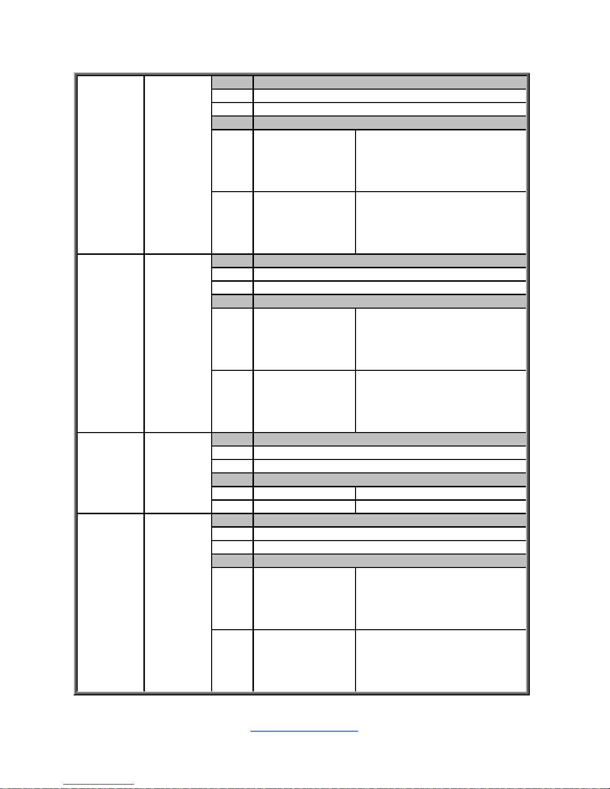
1.2 Hardware Specifications
TYAN S5542 (S5542WGM2NR)
Processor
Supported CPU
Series
Intel Xeon E3-1200 v5 series processors
Socket Type / Q'ty LGA1151 / (1)
Thermal Design
Power (TDP)
wattage
Max up to 80W
Chipset PCH Intel C232
Memory
Supported DIMM
Qty
(4) DIMM slots
DIMM Type / Speed Unbuffered ECC UDIMM DDR4 2133
Capacity Up to 64GB
Memory channel 2 Channels
Memory voltage 1.2V
Expansion
Slots
PCI-E
(1) PCI-E Gen.3 x16 slot (w/ x8 link) / (2) PCI-E
Gen.3 x1 slot
LAN
Port Q'ty (2) GbE ports + (1) dedicated for IPMI
Controller Intel I210
PHY
Broadcom BCM5221 PHY (dedicated for IPMI
connection)
Storage SAS Connector (2) Mini-SAS HD connectors (totally support 8 ports)

http://www.tyan.com
6
Controller LSI SAS3008
Speed 12.0 Gb/s
RAID RAID 0/1/1E/10 (LSI Integrated RAID)
SATA
Connector (6) SATA
Controller Intel C232
Speed 6.0 Gb/s
RAID RAID 0/1/10/5 (Intel RST)
Graphic
Connector type D-Sub 15-pin
Resolution Up to 1920x1200
Chipset Aspeed AST2400
Input /Output
USB
(3) USB2.0 ports (2 via cable, 1 Type-A) / (6) USB3.0
ports (4 at rear, 2 via cable)
COM (2) ports (1 at rear, 1 via cable)
SAS (2) Mini-SAS HD (4-in-1) connectors
VGA (1) D-Sub 15-pin VGA port
RJ-45 (2) GbE ports, (1) Dedicated for IPMI
PSMI (1) 1x5-pin header
Others (1) Reset button/ (1) Power button
SATA (6) SATA-III connectors
System
Monitoring
Chipset Aspeed AST2400
Voltage
Monitors voltage for CPU, memory, chipset & power
supply
Fan Total (4) 4-pin headers
Temperature
Monitors temperature for CPU & memory & system
environment
LED
Over temperature warning indicator / Fan & PSU fail
LED indicator
Others Watchdog timer support
Server
Management
Onboard Chipset Onboard Aspeed AST2400
AST2400 IPMI
Feature
IPMI 2.0 compliant baseboard management
controller (BMC) / Supports storage over IP and
remote platform-flash / USB 2.0 virtual hub
AST2400 iKVM
Feature
24-bit high quality video compression / 10/100 Mb/s
MAC interface
BIOS
Brand / ROM size AMI / 16MB
Feature
Hardware Monitor / ACPI 5.0 / SMBIOS
3.0/PnP/Wake on LAN / ACPI sleeping states
S3,S4,S5 / Boot from USB device ,PXE via
LAN ,Storage / User Configurable FAN PWM Duty
Cycle / Console Redirection
Physical
Dimension
Form Factor ATX
Board Dimension 12"x9.6" (305x243.8mm)
Operating
System
OS supported list Please refer to our Intel OS supported list.

http://www.tyan.com
7
Regulation
FCC (DoC) Class A
CE (DoC) Yes
Operating
Environment
Operating Temp. 10° C ~ 35° C (50° F~ 95° F)
Non-operating
Temp.
- 40° C ~ 70° C (-40° F ~ 158° F)
In/Non-operating
Humidity
90%, non-condensing at 35° C
RoHS RoHS 6/6 Compliant Yes
Package
Contains
Motherboard (1) S5542 Motherboard
Manual (1) Web User's manual / (1) Quick Installation Guide
Installation CD (1) TYAN installation CD
TYAN S5542 (S5542GM2NR)
Processor
Supported CPU
Series
Intel Xeon E3-1200 v5 series processors
Socket Type / Q'ty LGA1151 / (1)
Thermal Design
Power (TDP)
wattage
Max up to 80W
Chipset PCH Intel C232
Memory
Supported DIMM
Qty
(4) DIMM slots
DIMM Type / Speed Unbuffered ECC UDIMM DDR4 2133
Capacity Up to 64GB
Memory channel 2 Channels
Memory voltage 1.2V
Expansion
Slots
PCI-E
(1) PCI-E Gen.3 x16 slot (w/ x8 link) / (1) PCI-E
Gen.3 x8 slot / (2) PCI-E Gen.3 x1 slot
LAN
Port Q'ty (2) GbE ports + (1) dedicated for IPMI
Controller Intel I210
PHY
Broadcom BCM5221 PHY (dedicated for IPMI
connection)
Storage SATA
Connector (6) SATA
Controller Intel C232
Speed 6.0 Gb/s
RAID RAID 0/1/10/5 (Intel RST)
Graphic
Connector type D-Sub 15-pin
Resolution Up to 1920x1200
Chipset Aspeed AST2400
Input /Output
USB
(3) USB2.0 ports (2 via cable, 1 Type-A) / (6) USB3.0
ports (4 at rear, 2 via cable)
COM (2) ports (1 at rear, 1 via cable)

http://www.tyan.com
8
VGA (1) D-Sub 15-pin VGA port
RJ-45 (2) GbE ports, (1) Dedicated for IPMI
PSMI (1) 1x5-pin header
Others (1) Reset button/ (1) Power button
SATA (6) SATA-III connectors
System
Monitoring
Chipset Aspeed AST2400
Voltage
Monitors voltage for CPU, memory, chipset & power
supply
Fan Total (4) 4-pin headers
Temperature
Monitors temperature for CPU & memory & system
environment
LED
Over temperature warning indicator / Fan & PSU fail
LED indicator
Others Watchdog timer support
Server
Management
Onboard Chipset Onboard Aspeed AST2400
AST2400 IPMI
Feature
IPMI 2.0 compliant baseboard management
controller (BMC) / Supports storage over IP and
remote platform-flash / USB 2.0 virtual hub
AST2400 iKVM
Feature
24-bit high quality video compression / 10/100 Mb/s
MAC interface
BIOS
Brand / ROM size AMI / 16MB
Feature
Hardware Monitor / ACPI 5.0 / SMBIOS
3.0/PnP/Wake on LAN / ACPI sleeping states
S3,S4,S5 / Boot from USB device ,PXE via
LAN ,Storage / User Configurable FAN PWM Duty
Cycle / Console Redirection
Physical
Dimension
Form Factor ATX
Board Dimension 12"x9.6" (305x243.8mm)
Operating
System
OS supported list Please refer to our Intel OS supported list.
Regulation
FCC (DoC) Class A
CE (DoC) Yes
Operating
Environment
Operating Temp. 10° C ~ 35° C (50° F~ 95° F)
Non-operating
Temp.
- 40° C ~ 70° C (-40° F ~ 158° F)
In/Non-operating
Humidity
90%, non-condensing at 35° C
RoHS RoHS 6/6 Compliant Yes
Package
Contains
Motherboard (1) S5542 Motherboard
Manual (1) Web User's manual / (1) Quick Installation Guide
Installation CD (1) TYAN installation CD

http://www.tyan.com
9
TYAN S5542 (S5542GM4NR)
Processor
Supported CPU
Series
Intel Xeon E3-1200 v5 series processors
Socket Type / Q'ty LGA1151 / (1)
Thermal Design
Power (TDP)
wattage
Max up to 80W
Chipset PCH Intel C232
Memory
Supported DIMM
Qty
(4) DIMM slots
DIMM Type / Speed Unbuffered ECC UDIMM DDR4 2133
Capacity Up to 64GB
Memory channel 2 Channels
Memory voltage 1.2V
Expansion
Slots
PCI-E
(1) PCI-E Gen.3 x16 slot (w/ x8 link) / (1) PCI-E
Gen.3 x8 slot / (2) PCI-E Gen.3 x1 slot
LAN
Port Q'ty (4) ports + (1) dedicated for IPMI
Controller Intel I210
PHY
Broadcom BCM5221 PHY (dedicated for IPMI
connection)
Storage SATA
Connector (6) SATA
Controller Intel C232
Speed 6.0 Gb/s
RAID RAID 0/1/10/5 (Intel RST)
Graphic
Connector type D-Sub 15-pin
Resolution Up to 1920x1200
Chipset Aspeed AST2400
Input /Output
USB
(3) USB2.0 ports (2 via cable, 1 Type-A) / (6) USB3.0
ports (4 at rear, 2 via cable)
COM (2) ports (1 at rear, 1 via cable)
VGA (1) D-Sub 15-pin VGA port
RJ-45 (4) GbE ports, (1) Dedicated for IPMI
PSMI (1) 1x5-pin header
Others (1) Reset button/ (1) Power button
SATA (6) SATA-III connectors
System
Monitoring
Chipset Aspeed AST2400
Voltage
Monitors voltage for CPU, memory, chipset & power
supply
Fan Total (4) 4-pin headers
Temperature
Monitors temperature for CPU & memory & system
environment
LED
Over temperature warning indicator / Fan & PSU fail
LED indicator
http://www.tyan.com
10
Others Watchdog timer support
Server
Management
Onboard Chipset Onboard Aspeed AST2400
AST2400 IPMI
Feature
IPMI 2.0 compliant baseboard management
controller (BMC) / Supports storage over IP and
remote platform-flash / USB 2.0 virtual hub
AST2400 iKVM
Feature
24-bit high quality video compression / 10/100 Mb/s
MAC interface
BIOS
Brand / ROM size AMI / 16MB
Feature
Hardware Monitor / ACPI 5.0 / SMBIOS
3.0/PnP/Wake on LAN / ACPI sleeping states
S3,S4,S5 / Boot from USB device ,PXE via
LAN ,Storage / User Configurable FAN PWM Duty
Cycle / Console Redirection
Physical
Dimension
Form Factor ATX
Board Dimension 12"x9.6" (305x243.8mm)
Operating
System
OS supported list Please refer to our Intel OS supported list.
Regulation
FCC (DoC) Class A
CE (DoC) Yes
Operating
Environment
Operating Temp. 10° C ~ 35° C (50° F~ 95° F)
Non-operating
Temp.
- 40° C ~ 70° C (-40° F ~ 158° F)
In/Non-operating
Humidity
90%, non-condensing at 35° C
RoHS RoHS 6/6 Compliant Yes
Package
Contains
Motherboard (1) S5542 Motherboard
Manual (1) Web User's manual / (1) Quick Installation Guide
Installation CD (1) TYAN installation CD
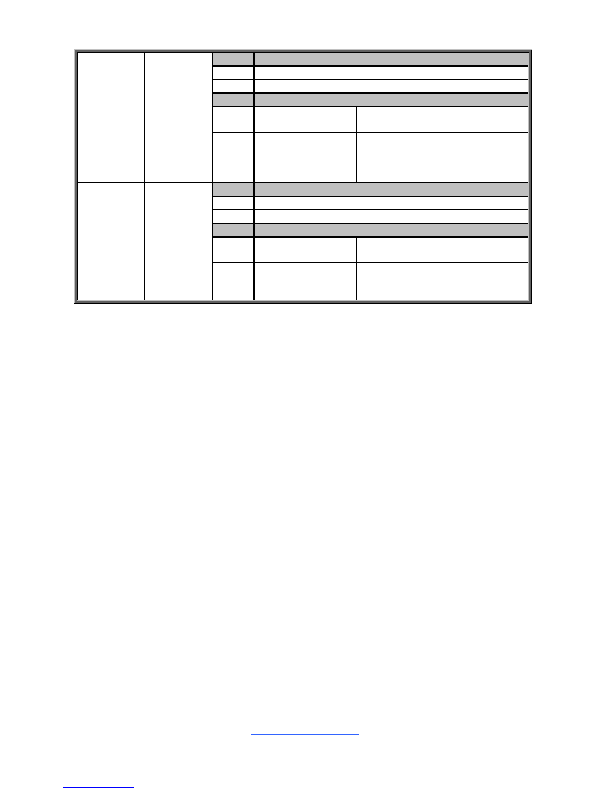
TYAN S5542-UHE (S5542G2NR-UHE)
Processor
Supported CPU
Series
Intel Xeon E3-1200 v5 series processors
Socket Type / Q'ty LGA1151 / (1)
Thermal Design
Power (TDP)
wattage
Max up to 80W
Chipset PCH Intel C236
Memory
Supported DIMM
Qty
(4) DIMM slots
DIMM Type / Speed Unbuffered ECC UDIMM DDR4 2133
Capacity Up to 64GB
Memory channel 2 Channels
Memory voltage 1.2V

http://www.tyan.com
11
Expansion
Slots
PCI-E
(1) PCI-E Gen.3 x16 slot (w/ x8 link) / (1) PCI-E Gen3
x8 slot ( w/ x4 link) / (1) PCI-E Gen.3 x8 slot / (2) PCIE Gen.3 x1 slot
LAN
Port Q'ty (2) GbE ports
Controller Intel I210
Storage SATA
Connector (8) SATA
Controller Intel C236
Speed 6.0 Gb/s
RAID RAID 0/1/10/5 (Intel RST)
Graphic
Connector type D-Sub 15-pin
Chipset Intel Processor Graphics(pGFX)
Input /Output
USB
(3) USB2.0 ports (2 via cable, 1 Type-A) / (6) USB3.0
ports (4 at rear, 2 via cable)
COM (2) ports (1 at rear, 1 via cable)
VGA (1) D-Sub 15-pin VGA port
RJ-45 (2) GbE ports
PSMI (1) 1x5-pin header
Others (1) Reset button/ (1) Power button
SATA (8) SATA-III connectors
System
Monitoring
Chipset Aspeed AST1400
Voltage
Monitors voltage for CPU, memory, chipset & power
supply
Fan Total (4) 4-pin headers
Temperature Monitors temperature for CPU & system environment
LED
Over temperature warning indicator / Fan & PSU fail
LED indicator
Others Watchdog timer support
BIOS
Brand / ROM size AMI / 16MB
Feature
Hardware Monitor / ACPI 5.0 / SMBIOS
3.0/PnP/Wake on LAN / ACPI sleeping states
S3,S4,S5 / Boot from USB device ,PXE via
LAN ,Storage / User Configurable FAN PWM Duty
Cycle / Console Redirection
Physical
Dimension
Form Factor ATX
Board Dimension 12"x9.6" (305x243.8mm)
Operating
System
OS supported list Please refer to our Intel OS supported list.
Regulation
FCC (DoC) Class A
CE (DoC) Yes
Operating
Environment
Operating Temp. 10° C ~ 35° C (50° F~ 95° F)
Non-operating
Temp.
- 40° C ~ 70° C (-40° F ~ 158° F)
In/Non-operating
Humidity
90%, non-condensing at 35° C

http://www.tyan.com
12
RoHS RoHS 6/6 Compliant Yes
Package
Contains
Motherboard (1) S5542 Motherboard
Manual (1) Web User's manual / (1) Quick Installation Guide
Installation CD (1) TYAN installation CD
TYAN S5542-UHE (S5542G2NR-UHE-M2)
Processor
Supported CPU
Series
Intel Xeon E3-1200 v5 series processors
Socket Type / Q'ty LGA1151 / (1)
Thermal Design
Power (TDP)
wattage
Max up to 80W
Chipset PCH Intel C236
Memory
Supported DIMM
Qty
(4) DIMM slots
DIMM Type / Speed Unbuffered ECC UDIMM DDR4 2133
Capacity Up to 64GB
Memory channel 2 Channels
Memory voltage 1.2V
Expansion
Slots
PCI-E
(1) PCI-E Gen.3 x16 slot (w/ x8 link) / (1) PCI-E Gen3
x8 slot ( w/ x4 link) / (1) PCI-E Gen.3 x8 slot / (2) PCIE Gen.3 x1 slot
LAN
Port Q'ty (2) GbE ports
Controller Intel I210
SATA
Connector (7) SATA
Storage Controller Intel C236
Speed 6.0 Gb/s
RAID RAID 0/1/10/5 (Intel RST)
M.2 connector (1) M.2 connector (2242 only)
Graphic
Connector type D-Sub 15-pin
Chipset Intel Processor Graphics(pGFX)
Input /Output
USB
(3) USB2.0 ports (2 via cable, 1 Type-A) / (6) USB3.0
ports (4 at rear, 2 via cable)
COM (2) ports (1 at rear, 1 via cable)
VGA (1) D-Sub 15-pin VGA port
RJ-45 (2) GbE ports
PSMI (1) 1x5-pin header
Others
(1) Reset button/ (1) Power button/ (1) M.2 NGFF
connector
SATA (7) SATA-III connectors
System
Monitoring
Chipset Aspeed AST1400
Voltage Monitors voltage for CPU, memory, chipset & power

http://www.tyan.com
13
supply
Fan Total (4) 4-pin headers
Temperature Monitors temperature for CPU & system environment
LED
Over temperature warning indicator / Fan & PSU fail
LED indicator
Others Watchdog timer support
BIOS
Brand / ROM size AMI / 16MB
Feature
Hardware Monitor / ACPI 5.0 / SMBIOS
3.0/PnP/Wake on LAN / ACPI sleeping states
S3,S4,S5 / Boot from USB device ,PXE via
LAN ,Storage / User Configurable FAN PWM Duty
Cycle / Console Redirection
Physical
Dimension
Form Factor ATX
Board Dimension 12"x9.6" (305x243.8mm)
Operating
System
OS supported list Please refer to our Intel OS supported list.
Regulation
FCC (DoC) Class A
CE (DoC) Yes
Operating
Environment
Operating Temp. 10° C ~ 35° C (50° F~ 95° F)
Non-operating
Temp.
- 40° C ~ 70° C (-40° F ~ 158° F)
In/Non-operating
Humidity
90%, non-condensing at 35° C
RoHS RoHS 6/6 Compliant Yes
Package
Contains
Motherboard (1) S5542 Motherboard
Manual (1) Web User's manual / (1) Quick Installation Guide
Installation CD (1) TYAN installation CD

http://www.tyan.com
14
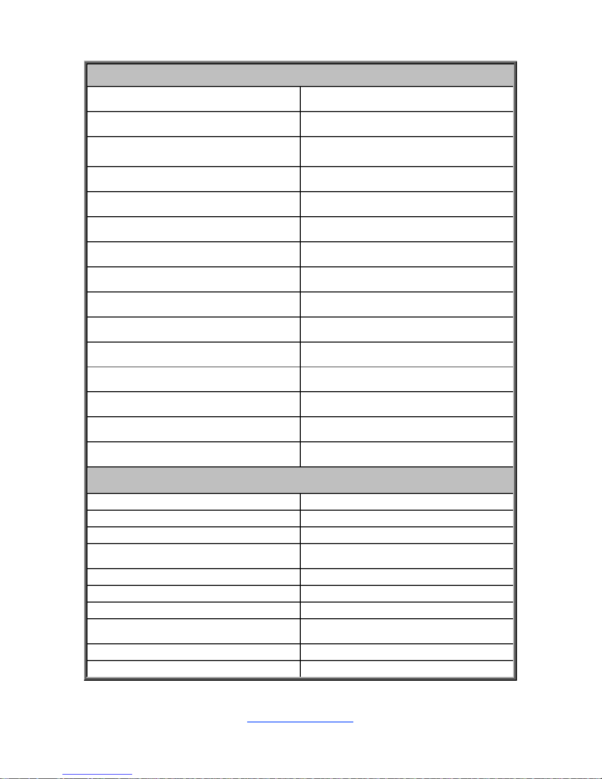
5 SKU Comparison Table
Part Number BMC PCH
Expand. slot
SAS
12
Gb/s
SAS
Raid
SATA
6
Gb/s
1G
LAN
USB
3.0
M.2
(NGFF)
X16 / X8 / X4
/ x1
S5542GM2NR Yes C232 1 / 1 / 0 / 2 0
No 6
2 4 0
S5542WGM2NR Yes C232 1 / 0 / 0 / 2 8
Yes 6
2 4 0
S5542GM4NR Yes C232 1 / 1 / 0 / 2 0
No 6
4 4 0
S5542G2NR-
UHE
No C236 1 / 2 / 0 / 2 0
No 8
2 4 0
S5542G2NR-
UHE-M2
No C236 1 / 2 / 0 / 2 0
No 7
2 4 1
1.3 Software Specifications
For OS (operation system) support, please check with TYAN® support for latest
information.

http://www.tyan.com
15
Chapter 2: Board Installation
You are now ready to install your motherboard.
How to install our products right… the first time
The first thing you should do is reading this user’s manual. It contains important
information that will make configuration and setup much easier. Here are some
precautions you should take when installing your motherboard:
(1) Ground yourself properly before removing your motherboard from the
antistatic bag. Unplug the power from your computer power supply and
then touch a safely grounded object to release static charge (i.e. power
supply case). For the safest conditions, MiTAC recommends wearing a
static safety wrist strap.
(2) Hold the motherboard by its edges and do not touch the bottom of the
board, or flex the board in any way.
(3) Avoid touching the motherboard components, IC chips, connectors,
memory modules, and leads.
(4) Place the motherbo ard on a g roun ded antist atic surface or on the antist ati c
bag that the board was shipped in.
(5) Inspect the board for damage.
The following pages include details on how to install your motherboard into your
chassis, as well as installing the processor, memory, disk drives and cables.
NOTE: Do not apply power to the board if it has been damaged.
http://www.tyan.com
16
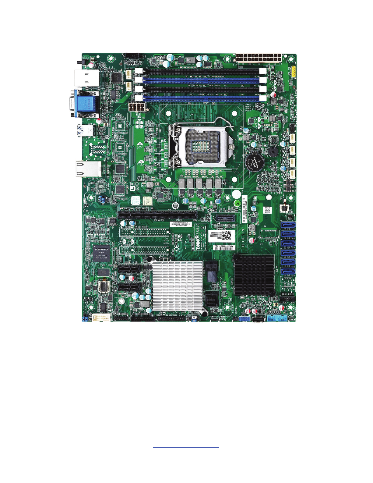
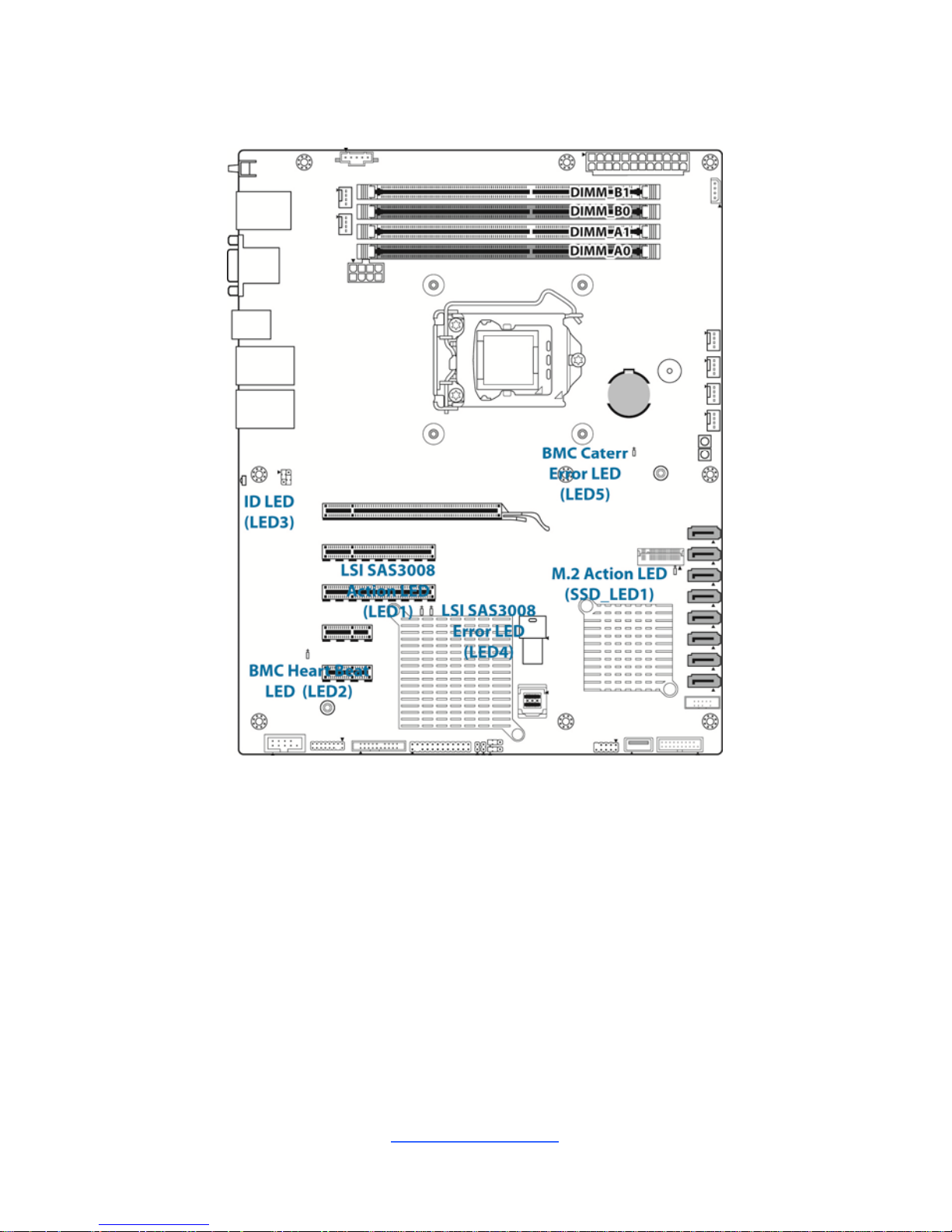
2.1 Board Image
S5542
This picture is representative of the latest board revision available at the time of
publishing. The board you receive may not look exactly like the above picture.
http://www.tyan.com
17
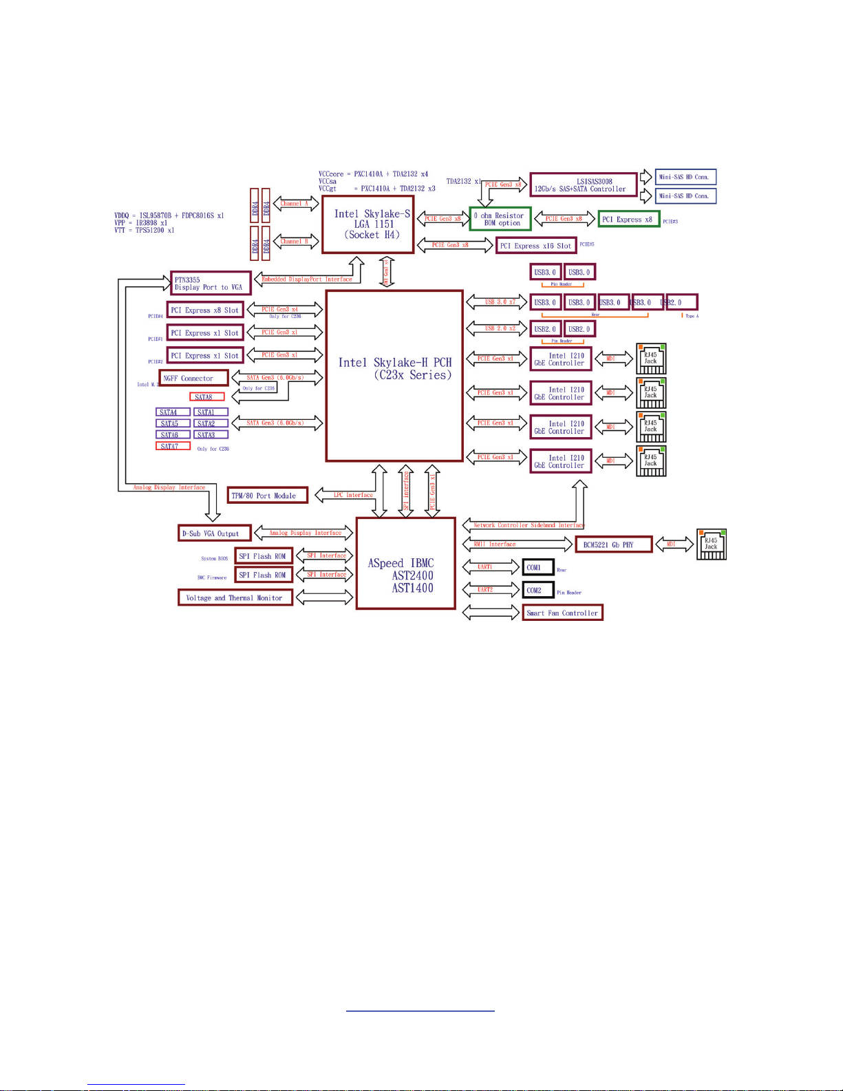
2.2 Block Diagram
S5542 Block Diagram
http://www.tyan.com
18
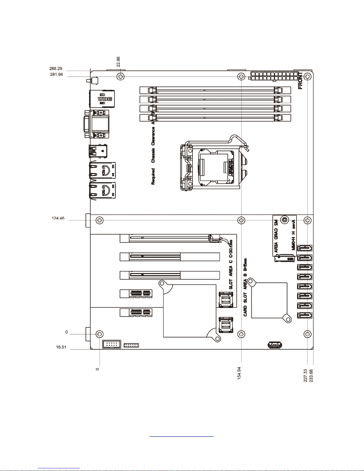
2.3 Mainboard Mechanical Drawing

http://www.tyan.com
19
2.4 Board Parts, Jumpers and Connectors
This diagram is representative of the latest board revision available at the time of
publishing. The board you receive may not look exactly like the above diagram. But
for the DIMM number please refer to the above placement for memory installation.
For the latest board revision, please visit our web site at http://www.tyan.com.
http://www.tyan.com
20
Connectors/Slots
1 ID LED Button (ID_BTN)
16 SATA Port (SATA 3.0, 6 Gbit/s)
(SATA6, J40)
2 LAN5 Port / USB Port (USB 3.0)*2 (J2)
17 SATA Port (SATA 3.0, 6 Gbit/s)
(SATA5, J41)
3 VGA Port (D-Sub) / COM Port (RS-232)
(J10)
18 SATA Port (SATA 3.0, 6 Gbit/s)
(SATA4, J42)
4 USB Port (USB 3.0)*2 (J5)
19 SATA Port (SATA 3.0, 6 Gbit/s)
(SATA3, J43)
5 LAN3, LAN4 Port (RJ-45)*2 (J8)
20 SATA Port (SATA 3.0, 6 Gbit/s)
(SATA2, J44)
6 LAN1, LAN2 Port (RJ-45)*2 (J7)
21 SATA Port (SATA 3.0, 6 Gbit/s)
(SATA1, J45)
7 PCI Express Slot (x16 Slot, w/x8 link)
(PCIE1)
22 SATA Port (SATA 3.0, 6 Gbit/s)
(SATA0, J46)
8 PCI Express Slot (x8 Slot, w/x4 link)
(J12)
23 M.2 (SATA 3.0, 6 Gbit/s, NGFF) (U57)
9 PCI Express Slot (x8 Slot, w/x8 link)
(J11)
24 8-Pin CPU Power Suppiy Connector
(PWRCONN1, PW2)
10 PCI Express Slot (x1 Slot, w/x1 link)
(J18)
25 DIMM_A0 (DDR4, Blue, Address:0xA0)
(J8C1)
11 PCI Express Slot (x1 Slot, w/x1 link)
(J17)
26 DIMM_A1 (DDR4, Black,
Address:0xA2) (J8C2)
12 SAS Port (LSI SAS3008, MINI SAS, 2
Port, 12 Gbit/s) (J28)
27 DIMM_B0 (DDR4, Blue, Address:0xA4)
(J8C3)
13 SAS Port (LSI SAS3008, MINI SAS, 2
Port, 12 Gbit/s) (J29)
28 DIMM_B1 (DDR4, Black,
Address:0xA6) (J8C4)
14 USB Port (USB2.0, Type-A, 480M/s)
(J33)
29 ATX 24-Pin Power Supply Connector
(J32, PW1)
15 SATA Port (SATA 3.0, 6 Gbit/s)
(SATA7, J39)
Headers
A PSMI Pin Header (J16) K Reset button (J36)
B System FAN5 Pin Header (J15) L Power button (J37)
C CPU Fan, PIN Header (J14) M System FAN4 Pin Header (J47)
D RS-232_DB-9_COM-Port_2 Pin
Header (J9)
N System FAN3 Pin Header (J48)
E TPM, Debug PIN Header (J13) O System FAN2 Pin Header (J49)
F System FAN Board Pin Header (J19) P System FAN1 Pin Header (J50)
G SSI FP I/O PIN Header (J20) Q IPMB Pin Header (J51)
H USB Header (USB 2.0, 480M/s)* 2
(FP_USB_1)
R LAN2 LED (J23)
I USB Header (USB 3.0, ,5G/s)* 2 (J35) S LAN3 LED (J24)
J SATA SGPIO Pin Header (HBA) (J34)
http://www.tyan.com
21
Jumpers LED Indicators
a SPI Bus Select Jumper (J111) i ID LED, Blue (LED3)
b CMOS Clear Jumper (J26) ii BMC Heart Beat LED, Green (LED2)
c ME Firmware Update Jumper (J256)
iii LSI SAS3008 Action LED, Green
(LED1)
iv LSI SAS3008 Error LED, Red (LED4)
v M.2 Action LED, Green (SSD_LED1)
vi BMC Caterr Error LED, Red (LED5)
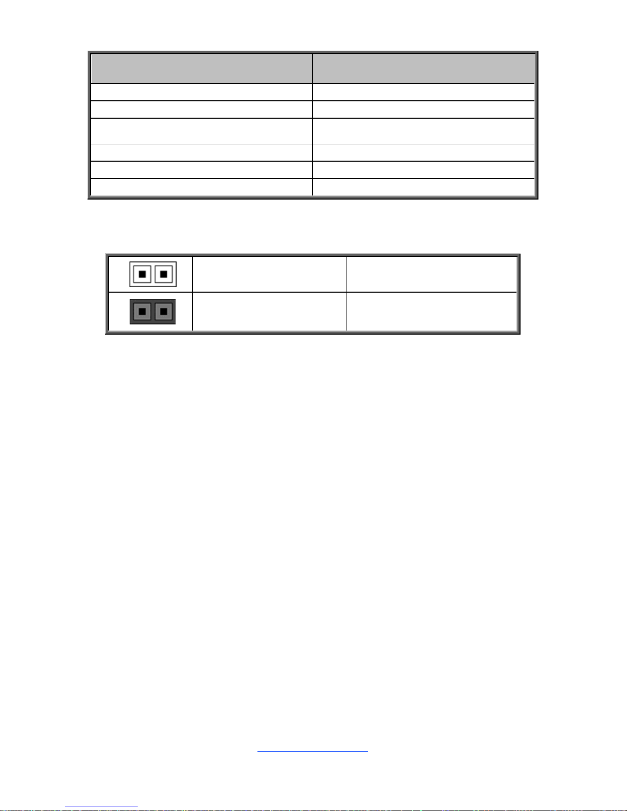
Jumper Legend
OPEN - Jumper OFF
Without jumper cover
CLOSED - Jumper ON
With jumper cover
http://www.tyan.com
22
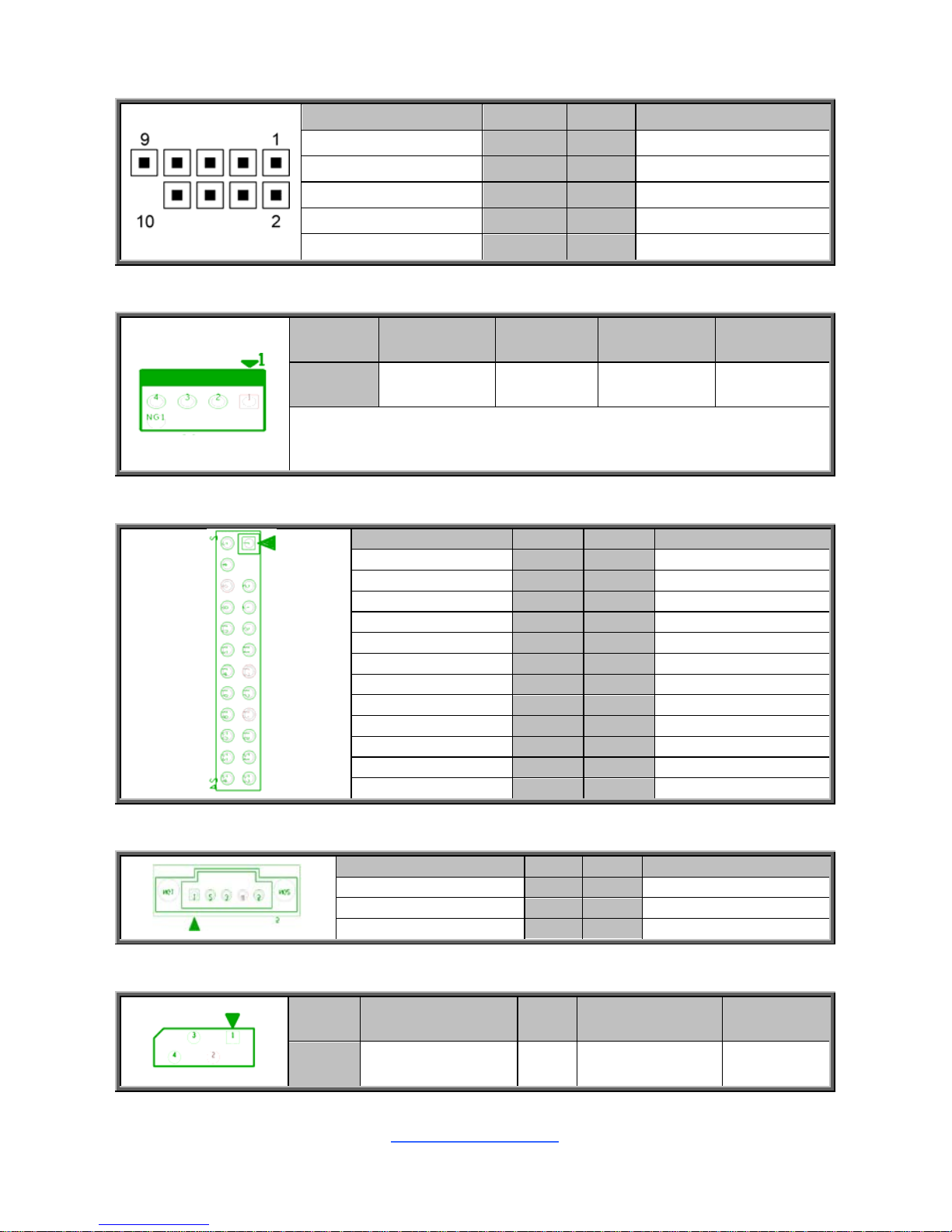
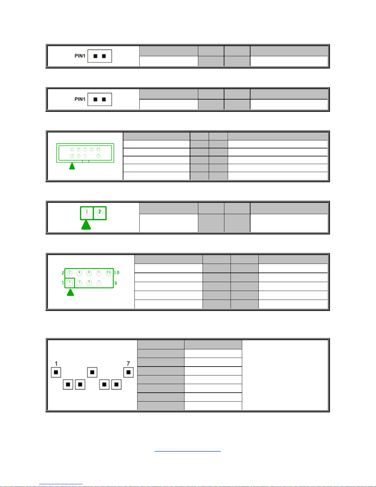
J9: COM2 Port Header
Signal Pin Pin Signal
DCD 1 2 DSR
RXD 3 4 RTS
TXD 5 6 CTS
DTR 7 8 RI
GND 9 10 KEY-Pin
J14(CPU FAN) / J50, J49, J48, J47, J15 (SYS_FAN1~5) :4-pin FAN Connector
Pin 1 2 3 4
Signal GND +12V NC NC
Use this header to connect the cooling fan to your motherboard to
keep the system stable and reliable.
J20: Front Panel Header
Signal Pin Pin Signal
PWRLED+ 1 2
VCC3_AUX
KEY 3 4
IDLED+
PWRLED- 5 6
IDLED-
HDDLED+ 7 8
SYS_FAULT1-
HDDLED- 9 10
SYS_FAULT2-
PWR_SW# 11 12
LAN1LED+
GND 13 14
LAN1LED-
RESET_SW# 15 16
SMBDATA
GND 17 18
SMBCLK
IDLED_SW# 19 20
INTRUSION#
TEMP SENSOR 21 22
LAN2LED+
NMI_SW# 23 24
LAN2LED-
J16: PSMI Connector
Signal Pin Pin Signal
SMB_CLK 1 2 SMB_DAT
SMB_ALERT# 3 4 GND
VCC3 5
J51: IPMB Pin Header
Pin 1 2 3 4
Signal BMC_SMB_DATA GND BMC_SMB_CLK VCC3_AUX
http://www.tyan.com
23
J23: LAN2 LED
Signal Pin Pin Signal
VCC3_AUX 1 2 ACT#
J24: LAN3 LED
Signal Pin Pin Signal
VCC3_AUX 1 2 ACT#
J34: SATA SGPIO Pin Header
Signal Pin Pin Signal
SMBCLK 1 2 SDATAOUT0
SMBDATA 3 4 SDATAOUT1
GND 5 6 SLOAD
KEY 7 8 SCLOCK
NC 9 10 CLK
INTRD1: Chassis Intrusion Pin Header
Signal Pin Pin Signal
INTRUSION# 1 2 GND
FP_USB_1 Front USB2.0 Header (blue)
Signal Pin Pin Signal
VCC 1 2 VCC
USBD- 3 4 USBD-
USBD+ 5 6 USBD+
GND 7 8 GND
KEY 9 10 NC
SATA0 (J46) / SATA1 (J45) / SATA2 (J44) / SATA3 (J43) / SATA4 (J42) / SATA5
(J41) / SATA6 (J40) / SATA7 (J39): SATA-III 6G Connector
PIN Define Pin
Connects to the Serial
ATA ready drives via
the Serial ATA cable.
1 GND
2 SATA TX DP
3 SATA TX DN
4 GND
5 SATA RX DN
6 SATA RX DP
7 GND
http://www.tyan.com
24
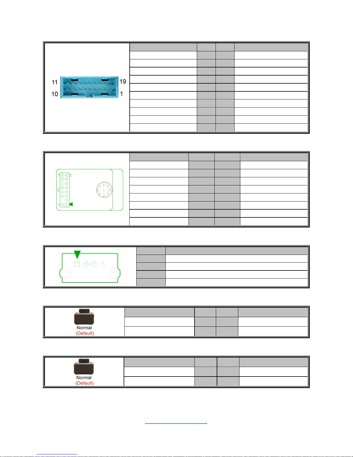
J35: USB3.0 Header
Signal Pin Pin Signal
1 VCCUSB3_FRONT
VCCUSB3_FRONT 19 2 USB30RX_4N_R
USB30RX_3N_R 18 3 USB30RX_4P_R
USB30RX_3P_R 17 4 GND
GND 16 5 USB30TX_4N_R
USB30TX_3N_R 15 6 USB30TX_4P_R
USB30TX_3P_R 14 7 GND
GND 13 8 USB_PCH DN2_R
USB_PCH_DN4_R 12 9 USB_PCH DP2_R
USB_PCH_DP4_R 11 10 USB_PCH_OC24_N_ID
J13: TYAN Module Header
Signal Pin Pin Signal
VCC3 1 2 FRAME
LAD0 3 4 KEY
LAD1 5 6 RESET#
LAD2 7 8 GND
LAD3 9 10 CLK
LSIRQ0# 11 12 GND
TPM_PRSNT 13 14 VCC3_AUX
NC 15 16 NC
J33 Vertical Type-A USB2.0onnector
Pin Signal
1 USB 5V Power
2 USB Data3 USB Data+
4 GND
J37: Power Switch Button
Signal Pin Pin Signal
FP_PWR_BTN_N 1 2 FP_PWR_BTN_N
GND 3 4 GND
J36: Reset Switch Button
Signal Pin Pin Signal
FP_RST_BTN_N 1 2 FP_RST_BTN_N
GND 3 4 GND
http://www.tyan.com
25
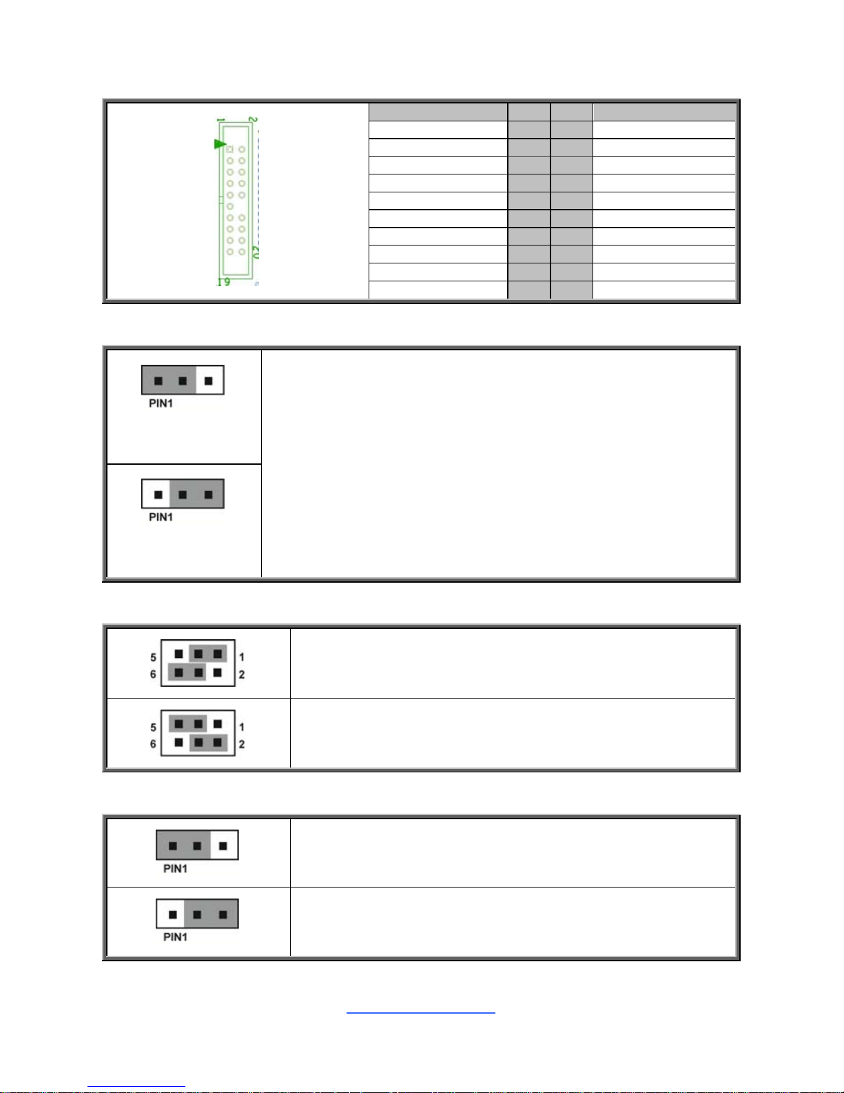
J19: Fan Connector Reserved for Barebone
Signal Pin Pin Signal
TACH1 1 2 TACH6
TACH2 3 4 TACH7
TACH3 5 6 TACH8
TACH4 7 8 TACH9
TACH5 9 10 TACH10
GND 11 12 -
PWM2 13 14 PWM1
TACH11 15 16 SMBDATA
TACH12 17 18 SMBCLK
VCC3_AUX 19 20 PWM3
J26: Clear CMOS Jumper
Normal, RTC
reset (Default)
You can reset the CMOS settings by using this jumper. This can be
useful if you have forgotten your system/setup password, or need to
clear the system BIOS setting.
1. Power off system and disconnect power connectors from the
motherboard.
2. Remove the jumper from Pin_2 and Pin_3 (Default setting).
3. Move the jumper cap to close Pin_1 and Pin_2 for several seconds
to Clear CMOS.
4. Put jumper cap back to Pin_2 and Pin_3 (Default setting).
5. Reconnect power connectors to the motherboard and power on
system.
Clear RTC
registers
J111: SPI Bus Select Jumper
Pin 1-3 and 4-6 Closed: PCH to SPI (Default)
Pin 2-4 and 3-5 Closed: BMC to SPI
J25: ME Firmware Update Jumper
Pin 1-2 Closed: Normal (Default)
Pin 2-3 Closed: ME Recovery
http://www.tyan.com
26
2.5 LED Definitions
http://www.tyan.com
27
LED1
LSI
SAS3008
Action LED
Pin Signal
+ +VCC3
- GND
State Description
OFF OFF
The LED shuts off when the SAS
controller not active and can not
be detected or properly initiated.
Blinking Green
The LED blinks per second to
indicate that the SAS controller is
active and working normally
LED2
BMC Heart
Beat LED
Pin Signal
+ +3V_AUX
- GND
State Description
OFF OFF
The LED shuts off when the BMC
controller cannot be detected or
properly initiated.
ON Green
The LED blinks per second to
indicate that the BMC controller
is working normally
LED3
Rear ID
LED
Pin Signal
+ + VCC3_AUX
- GND
State Description
OFF OFF OFF
ON Green ON
LED4
LSI
SAS3008
Error LED
Pin Signal
+ +VCC3
- GND
State Description
OFF OFF
The LED shuts off when System
and SAS controller is running
normally.
Blinking Red
The LED bright to indicate that
the SAS controller is not active
and errors
http://www.tyan.com
28
LED5
CAT Error
LED
Pin Signal
+ +VCC3
- GND
State Description
OFF OFF
The LED shuts off when System
and BMC is running normally.
ON Red
The LED lighted up when the
system has experienced a fatal
or catastrophic error and can not
continue to operate.
SSD_LED1
M.2 Action
LED,
Green
Pin Signal
+ +VCC3
- GND
State Description
OFF OFF
The LED shuts off when no M.2
devices or M.2 devices no active.
ON Green
The LED blinks per second to
indicate that M.2 devices is active
and working normally.
http://www.tyan.com
29
2.6 Installing the Processor and Heat sink
The S5542 supported Intel® processors are listed in section 1.2 Hardware
Specifications on page 5. Check our website at http://www.tyan.com for latest
processor support.
NOTE: MiTAC TYAN is not liable for damage as a result of operating an
unsupported configuration.
Processor Installation (SNB_H4 (LGA1151) for Intel Skylake CPU)
Follow the steps below to install the processors and heat sinks.
Please note that the illustrations are based on a SNB_H4 (LGA1151) which may not
look exactly like the motherboard you purcha sed. Therefore, the illustrations should
be held for your reference only.
NOTE: Please save and replace the CPU protection cap when returning for service.
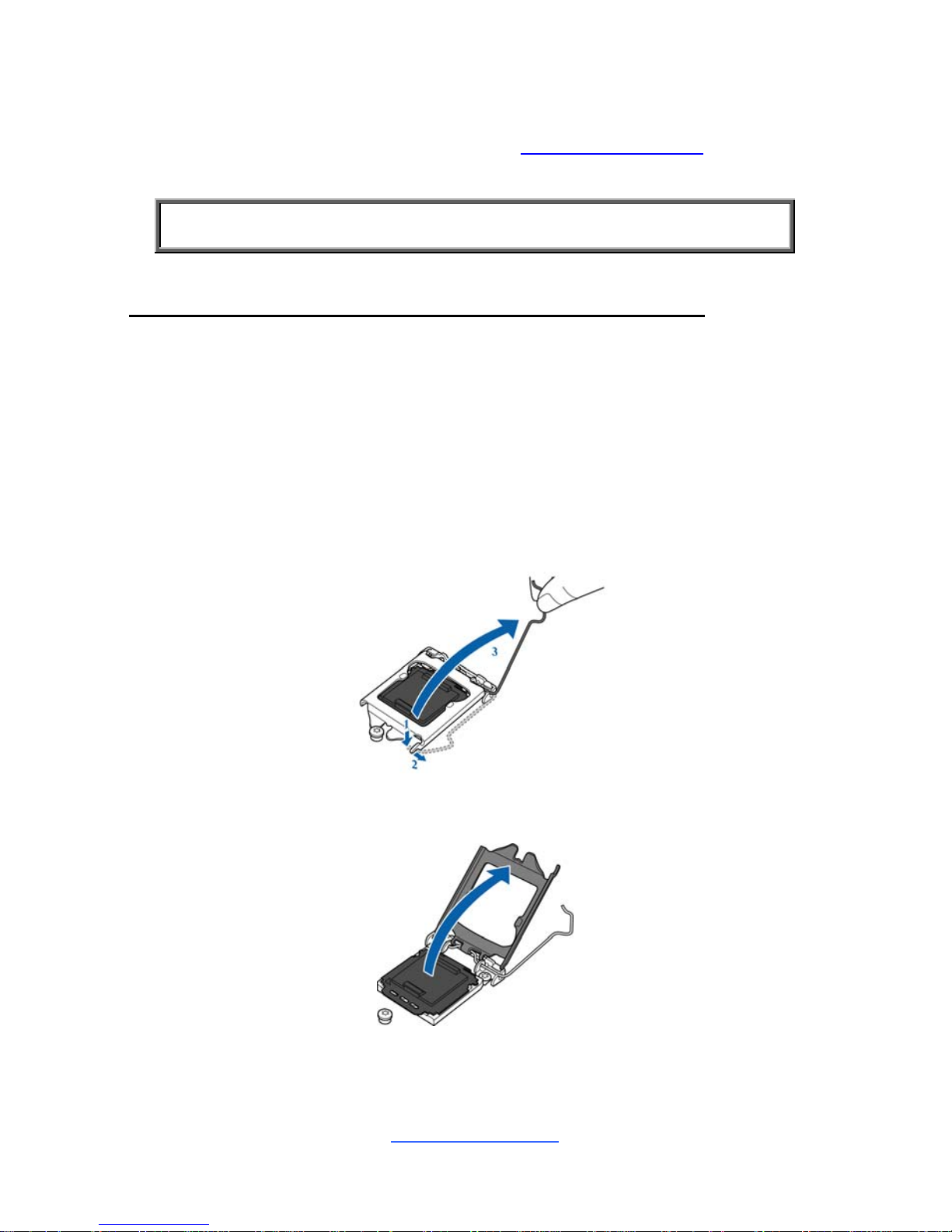
1. Locate the CPU socket.
2. Pull the CPU lever slightly away from the socket and then push it to a fully
open position.
3. Open the CPU socket cover.
http://www.tyan.com
30
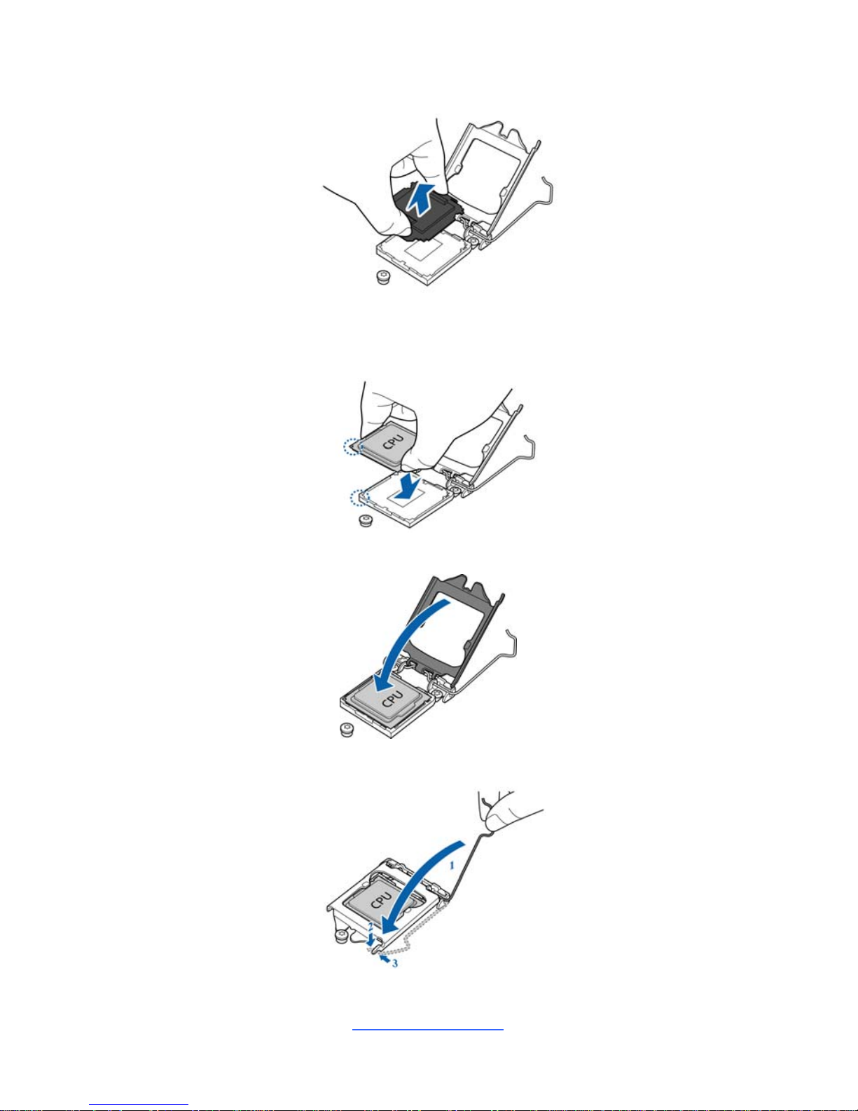
4. Remove the CPU protection cap.
5. Install the processor and make sure the gold arrow is located in the right
direction with two notches properly aligned.
6. Close the CPU socket cover.
7. Press the socket lever down to lock the CPU in place.
 Loading...