


MINOURA RDA Inter-Rim Ergo-10 / 50 Instruction manual
Please read this instructions carefully before use
(This figure is the Remote Control version)
Thank you for purchasing Minoura's Inter-Rim Ergo Trainer with RDA and Magturbo.
With its unique rim-drive system, the RDA Inter-Rim Magturbo is our most sophisticated bicycle home trainer for both road and mountain bikes. Minoura has long been an innovator in stationary trainers, and our new Inter-Rim trainer continues that tradition. The Rim Drive Action (RDA) system has special drive pulleys that contact only the rim, avoiding wear and tear to the tire and any unpleasant noise. With the RDA system, training is smoother, more adjustable, and quieter, and you avoid the cost of replacing worndown tires. The RDA system can handle almost any bicycle with a wheel diameter of 26 to 28 inches and is the best trainer yet for mountain bikes.
•Read all instructions carefully before use.
•Some assembly required.
•Keep the manual handy at all times. Lost instruction materials can be replaced through Minoura or your local dealer.
•Do NOT use trainer for any other purpose than instructed.
•The trainer is manufactured to precise standards. You may not disassemble or rebuild it.
•"Inter-Rim" and "RDA" are trademarks of Minoura and may not be copied.
-1 -

Please obey warning signs.
!
!
!
!
!
!
!
!
!
!
!
!
- 2 -
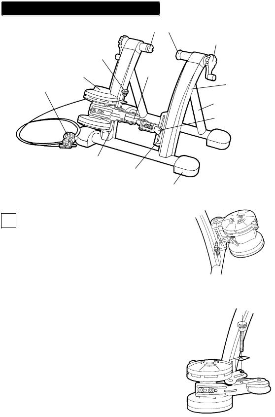
ASSEMBLING YOUR MINOURA TRAINER
Couplings
Hub-clamp handle
Mag Unit Height
Adjust Knob
Mag Unit |
Drive roller |
Frame
Remote Control
Lever
U-Leg
Drive-pulley lever
Mag unit installation |
|
|
slot |
Assistant roller unit |
|
|
|
|
|
installation slot |
(Fig. A) |
|
|
Rubber Foot Cap |
1 Open the frame and U-Leg and place on level floor.
2 |
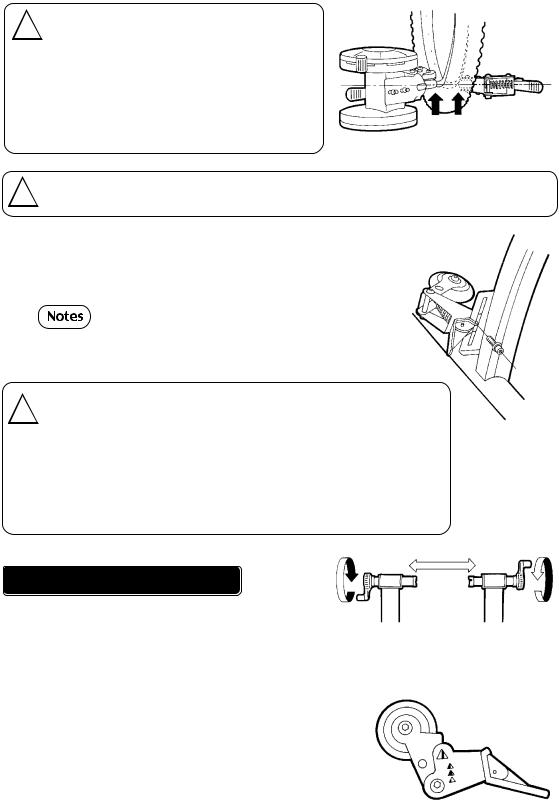
Prior to assembly of the Magturbo unit, locate the |
|
two bolts and two washers. Locate the left-side slot |
|
|
|
on the Minoura trainer. While placing the Magturbo |
|
unit at the desired position on the inside of the slot, |
|
attach it with bolts and washers by using the included |
|
hex wrench. (see Fig. B) |
|
After installing the Magturbo unit, put the Height |
|
Adjust Knob (maybe an option) through the hole on |
|
the pre-installed bracket on the left side slot, and then |
|
tighten it to the thread on the Magturbo support base. |
|
This optional Height Adjust Knob will help your |
|
adjustment of Magturbo’s height in order to fit the |
|
rubber roller properly to the rim side wall. (see Fig.C) |
|
- 3 - |
(Fig. B)
(Fig. C)
Mag unit must be assembled on the left side ! of RDA Trainer and the Assistant Roller Unit on the right. Do not mistake directions, see
diagram for accurate placement. After deciding the height of the pulleys tighten handle securely to avoid damage to equipment and/or rider. (see Fig. D)
! |
Handle with care! Damage may occur if Mag unit is dropped. |
|
Install the assistant roller unit to the right side of the frame, using |
3 |
|
|
the same process as with the left-side Mag unit. Make sure the |
|
|
|
assembly is secure and accurate. (see Fig. E) |
|
The Inter-Rim is foldable and portable without requiring future |
|
disassembly of the Magturbo unit and assistant roller unit. |
|
The Magturbo unit must be on the left side of the Inter-Rim |
!frame, and the assistant roller unit must be on the right side. Both drive pulleys must be adjusted so as not to touch the tire. You do not need to set this adjustment at this stage of the assembly --- you can adjust it later, before use. Once you have set the height of the pulleys, you must fix them firmly. If they are loose, they may break and/or damage your bicycle.
(Fig. D)
(Fig. E)
INSTALLING YOUR BICYCLE
1 |
Before installing your bicycle, rotate both hub-clamp handles counter-clockwise to |
|
create a wide clearance between the couplings. (see Fig. F) |
|
|
|
Place the bicycle's rear hub between the two couplings, |
2 |
|
|
making sure that the quick-release skewer (or hub nut) is not |
|
|
|
yet touching either couplings. Then rotate the hub-clamp |
|
handles clockwise to fix the rear hub. Tighten until securely |
|
fastened, but do not overtighten. |
|
During this attachment process, you should adjust the |
|
position of the rim with checking the Rim Center Position |
|
Indicator on the Assitant Roller. (see Fig. G) |
|
- 4 - |
(Fig. F)
(Fig. G)
 Loading...