


ICE
- 1 -
INSTRUCTION MANUAL
(version 1.1.2)

- 2 -
Introduction
Thank you for selecting the Minoura ICE (Interactive Cycling Experience) system.
ICE is an upgrade kit used in conjunction with your Minoura Magturbo trainer. Everything
you need to install ICE onto your existing Minoura trainer is included in this package.
Once installed, you will be able to enjoy training in a virtual world when connected to your PC
(IBM compatible with Windows 95 or 98).
ICE may also easily be uninstalled to return your Minoura trainer to its original configuration
for ease of transportation and use anywhere you want.
About UltraCoach™ Software?
The ICE package includes a CD-ROM which contains UltraCoach VR™ and UltraCoach
HRM™ softwares.
UltraCoach® was established by Dr. Kenneth Burres, a retired triathlete and an authority on
sport rehabilitation medical, and Paul Stewart, a triathlete and a computer engineer, in 1994.
You recieve the benefit of their experience in sports medicine training and coaching.
UltraCoach softwares provide the following features;
• Providing Realistic Virtual Courses (UltraCoachVR)
UltraCoach has created and exciting world that provides you with many virtual courses for
your computer. The program automatically controls the resistance of your trainer, so you get
a lifelike feel comparable to that of an outdoor ride. You will feel UltraCoach VR increase and
decrease the resistance levels depending on the course. You will even be able to experience
virtual drafting.
Three courses are included with your ICE unit. You get the 1996 Atlanta Olympic road
course, the Olympic Velodrome oval course, and a computer generated MTB course called
Field of Dreams.
In addition, many virtual course modules are offered as options when you are ready for a new
challenge. Currently, you can choose from courses like the Hawaii Kona 112 Miles Challenge,
race on the moon, or in the canals of Mars. New courses are constantly being developed and
you should contact UltraCoach directly or on the web for an updated course listing. Having
new courses readily available sets ICE apart from the competition.
UltraCoach’s 3-D engine is one of the best in the business. Other programs are constructed of

- 3 -
what is essentially, wallpaper, or the same scene over and over again. With UltraCoach soft-
ware, you see detail and get a real experience better than that of any other product
currentlyavailable. This, combined with the fact that UltraCoach VR also works with other
manufactyrers exercise equipment (such as thread mills, rowing machines, etc.), Ultracoach
and ICE are the natural choice.
For more information on UltraCoach, please visit their web site at www.ultracch.com.
• Multi Competition Mode (UltraCoach VR)
UltraCoach VR software provides you with three options for competition against other rid-
ers;
1. Compete with the computer generated opponents
You can program the speed of each computer-generated opponent. Each opponent is seen as
P1, P2 or P3 on your screen. You may also compete against UltraCoach’s exclusive
UltraRabbit™. UltraRabbit is a guide that may be passed, or passes you, depending on your
speed automatically.
2. Compete against yourself
Each time you race, you will be given the option of saving that race. If you choose this option,
you can race against your best times, or friends’ best times, and try to beat your best time.
3. Over the network or LAN (Local Area Network)
ICE allows you to compete against up to three other live opponents over the Internet or over
a LAN when connected through UltraCoach’s website.
Visit www.ultracch.com for more details.
•Providing Your Own Virtual Coach (UltraCoach HRM)
As mentioned earlier, you can save each workout on your computer’s hard drive that you can
customize with graphics that are included in the UltraCoach HRM software.
UltraCoach also offers analysis and recommendation based on your workout through their
UltraCoach Intelligence Technology. See the UltraCoach software manuals for more infor-
mation on this feature.

- 4 -
System Requirements
Below are the minimum specifications for running UltraCoachVR software.
•IBM compatible PC
User assembled PC may not work properly. Each system is designed and functions differently.
•Intel® Pentium™ 133MHz
A Pentium MMX™ 200MHz CPU is required for smooth animation. Pentium II™ 400MHz and
abovehave had some issues. See the UltraCoach or Minoura website for updates.
•Windows95™ or Windows98™
UltraCoach VR will not run in Windows 3.1™, Macintosh™, Be™, Unix™, Linux, or any operat
ing system other than Windows 95 or 98.
•VGA monitor or any graphical interface
•16MB RAM
•50MB hard drive space
•16 bit sound card
•2MB video RAM
NOTE:
EACH SYSTEM IS DIFFERENT AND YOUR COMPUTER MAY
ENCOUNTER FRAME FREEZES ONCE IN A WHILE. THIS IS
NORMAL AND TO BE EXPECTED.
Below are not must specifications, but we recommend to add them onto your PC for comfort-
able use of UltraCoachVR software.
•3D graphic accelerator card with a minimum of 4MB video RAM
We strongly recommend 3Dfx® VooDoo™, ATI® Rage Pro™ or nVIDIA® Riva TNT™ card.
If you install this kind of card onto your PC, make sure a cooling fan must be required to prevent
from any overheat problems.
•28.8K or higher baud modem or terminal adaptor for WebRace™

- 5 -
What Comes With ICE?
• 1 x Head Controller
• 1 x Motor Drive Unit
• 1 x Outer Cover
• 1 x AC Power Adaptor
• 1 x RS-232C Serial Cable (male-male)
• 1 x RS-232C Serial Cable (female-female)
• 1 x Cadence Sensor
• 1 x Cadence Sensor Bracket
• 1 x Alloy Rotor with Speed Sensor Sleeve
• 1 x 10mm Open Wrench
• 1 x 3mm Hex Wrench
• 1 x M6x12 Headless Bolt
• 1 x M6 Nut
• 4 x M3.5x40 Taping Screw
• 4 x M3.5x35 Taping Screw
• 2 x M3.5x30 Taping Screw
• 1 x M3.5x25 Tapping Screw
• 1 x M3.5x10 Taping Screw
• 1 x CD-ROM
• 1 x Update Program Diskett
• 1 x Instruction Manual
• 1 x Regitration Card
• 1 x Limited License Agreement
• 1 x Optional Course Guide
Which Model Of Magturbo Do You Have?
ICE is available for all the following Magturbo models which have a transparent outer cover
on the Mag resistance unit. Check to see if your model is listed below.
If your Minoura trainer is not listed below, ICE will not work and you will have to buy one of
the units found below.
Model Name Model Year
Super Team Magturbo 1994 - 1996
Super Magturbo 3 1994 - 1995
Super ATB Magturbo 1994 - 1995
Magturbo MR-1 & MR-1N 1995 -
Magturbo MR-1 Ergo 1998 - 1999
Magturbo Ergo-10 1999 -
Magturbo MR-3 1995 - 1996
Magturbo MR-5 & MR-5N 1995 -
Magturbo MR-5 Ergo 1998 - 1999
Magturbo Ergo-50 1999 -
Magturbo MA-2 1995 - 1996
Model Name Model Year
RDA InterRim 1996 - 1999
10th RDA InterRim Ergo 1998 - 1999
RDA InterRim Ergo-10 1999 -
RDA InterRim Ergo-50 1999 -
Mag Roller II 1994 - 1995
Action Mag Roller 1996 -

- 6 -
HOW TO SET-UP ICE
1.
Remove the original transparent outer cover of the Mag
resistance unit by removing the four screws found on
the transparent face plate.
At this time, you should set the shift lever to the H posi-
tion to make this step easier.
These screws will not be used to install ICE, but you
must keep them should you want to convert your
Minoura trainer back to its original configuration.
(see Fig. A)
(Fig. A)
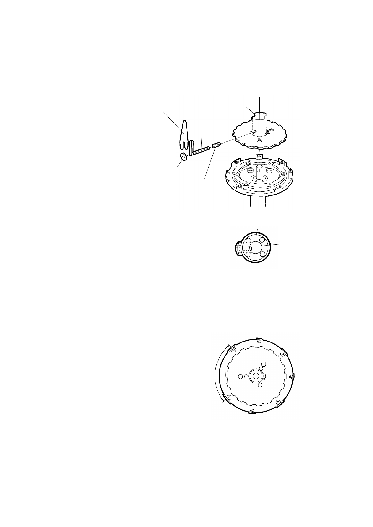
2.
Loosen the original M6x10 Headless Bolt which fixes the
Alloy Rotor Bushing to the shaft from its side. Then the
Alloy Rotor will be removable.
Keep the original Headless Bolt for restoring your Mag
unit to its original configuration.
(see Fig. B)
(Fig. B)
original
M6x10
Headless Bolt
Alloy Rotor
“H” position
3mm Hex Wrench
- 7 -
5.
Place the Motor Drive Unit on the Mag unit where you originally removed the face plate.
Follow the steps below to make sure that the Motor Drive Unit is lined up properly with the
Mag unit. To do this, follow the steps outlined below.
Step 1:
There are four larger holes with wider lip and
three smaller holes with narrower lip on the
Inner Housing of the Mag resistance unit. The
larger holes are for the connecting screws, and
smaller holes are for positioning pins.
Also you can see the double wide span between
the larger holes. This span is used for the shift
lever when the trainer is used in the original
condition without ICE.
(see Fig. E)
3.
Replace the Alloy Rotor with the one
included in your ICE system. The
one included in your ICE system has
a Speed Sensor Sleeve. Follow the
directions to the right (Fig. C) for
this replacement. The Speed Sen-
sor Sleeve is crucial in making the
ICE system work properly.
(see Fig. C)
(Fig. C)
4.
Secure the included longer M6x12 Headless Bolt and M6
Nut, and secure the Alloy Rotor firmly.
Make sure that the Alloy Rotor is fully inserted to the Shaft
and the tip of the Headless Bolt is installed onto the flat
point of the Shaft in order to avoid slippage of the Alloy
Rotor.
(see Fig. D)
(Fig. D)
Speed Sensor Sleeve
10mm Open Wrench
M6 Nut
3mm Hex
Wrench
M6x12 Headless Bolt
Shaft
Alloy Rotor Bushing
(Fig. E)
No Hole
Area
- 8 -
Step 2:
There are four holes and three pins on the Mo-
tor Drive Unit. You can see the position where
a pin is missing. It is the postion where the
Motor Drive Unit must meet the wider span
of the Inner Housing of the Mag resistance
unit.
(see Fig. F)
(Fig. F)
No Pin
Area
Step 3:
Hold the Motor Drive Unit in your hand and place it its Inner Housing in the correct
direction. You will know it is the correct direction because the magnets will repel
against each other. Once this step is achieved, go immediately to Step 6.
CAUTION:
Installation of the Motor Drive Unit in the
WRONG direction will cause the unit to
malfunction and not work. You must
follow all directions and pictures
precisely!!
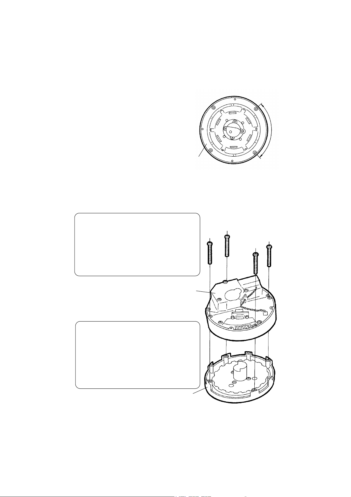
6.
Secure the Motor Drive Unit with four M3.5x40 self-tap-
ing screws to the Inner Housing. (see Fig. G)
M3.5x40
(or M3.5x35)
Screw
(Fig. G)
Motor Drive Unit
Inner Housing
Motor Drive Unit
CAUTION:
If you install ICE on the Mag unit which
original color of the outer cover is not gray
or yellow, but red, you must use the
shorter (M3.5x35) taping screws because
the depth of the screw holes on older
Inner Housing is too short for screw.
- 9 -
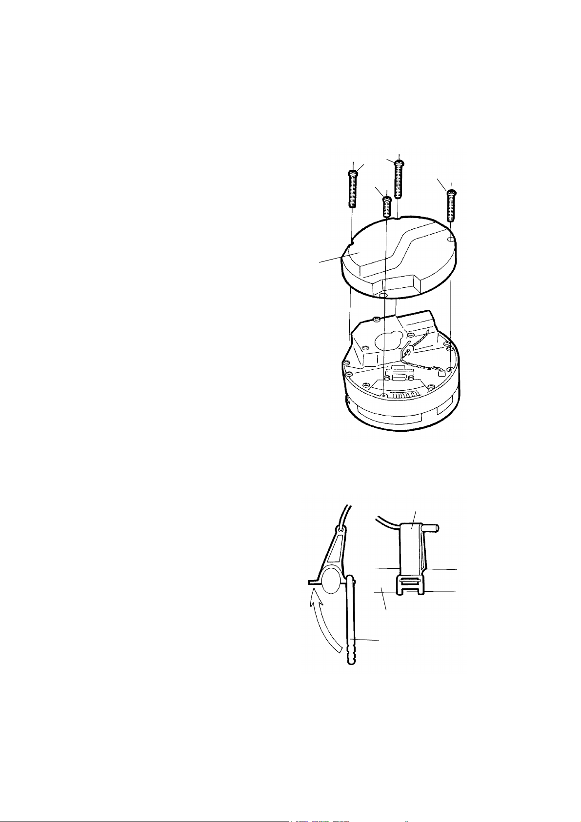
7.
Put the Outer Cover onto the Motor Drive Unit, and se-
cure it with included self taping screws.
Use the shortest screw for the position under the RS-
232C connector, and use the middle ones for the lower
stairs of the Outer Cover. The other longer screws are
used for the top of the cover.
(see Fig. H)
8.
Install the Head Controller onto your handlebar.
If it will not lock down securely, insert something like
handlebar tape, electrical tape, etc. between the handle-
bar and the bracket so the unit is securely attached to
your handlebar.
9.
Connect the Head Controller to the Motor Drive Unit
with the included RS-232C serial cable (male-to-male
connector in white). Wire should be routed along the
left side of the bicycle frame and AWAY from the crank
arms.
(Fig. H)
10.
Install the Cadence Sensor Magnet onto the left
crank arm with the supplied zip tie.
11.
Install the Cadence Sensor with the supplied
bracket on the left chainstay of your bike. Ad-
just the initial position so there is proper clear-
ance for the magnet on your crank arm to pass
within a few mm of the sensor. Once this is done,
plug the Snsor Cord into the Cadence jack on the
Head Controller. Route the cable carefully as
per the instructions in Step 9.
(see Fig. I)
(Fig. I)
Long
Middle
short
Cadence
Sensor
Cadence Sensor
Bracket
Chain Stay
Outer Cover

- 10 -
12.
Plug the AC Adaptor into the Head Controller. Make sure there is a little slack in the adaptor
cable and that it isn’t pulled to tight.
13.
Now it’s time to test the unit. Turn the power switch ON. The LED indicator will light up and
you will see the number “11” once the Motor Unit starts to move, and is initialized. The
motor moves on its own and needs no assistance from you.
Once initialized, the LED will show “55”. Once this happens, your unit is ready and you can
trun the Head Controller OFF now.
14.
Next, connect ICE to the serial port on your PC with the other included RS-232C serial cable
(female-to-female connector in gray). Be sure to connect the cable in the D-Sub 9 pin (usu-
ally your mouse port if you are using a serial mouse).
It is OK to disconnect your mouse at this point as the ICE program can be accessed from your
keyboard. You may be able to use Alt , Tab, Enter and four arrow keys instead of usig a
mouse when you select something on the screen. You may reconnect your mouse with no
problem AFTER completing your training.
Should you need a longer cable due to the location of the computer to your bike, you can
purchase a straight type cable (not a cross type) at your local computer store. This cable may
be referred to as a mouse "extension" cable.
- 11 -
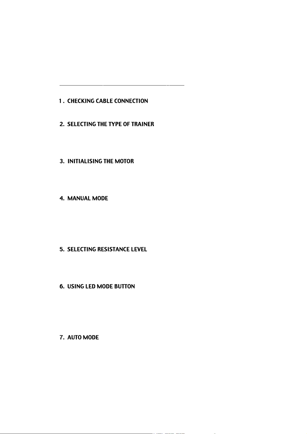
How To Operate The Head Controller
First, make sure all cables are properly connected as per the previous directions.
On the back of the Head Controller is a switch that allows you to choose the type of drive type
you need to use. There is a Tire and a RDA setting. If you use our rim drive trainer, set the
switch to RDA. If you use our tire drive unit, select the TIRE setting.
Turn the Power Switch ON. The LED will show 11 and the motor will turn back to its initial
position. Automatically, the LED will change to 55.
Step is now complete and the ICE system is ready to use.
You may use your ICE in a manual (no computer screen) mode. Using ICE this way gives you
20 levels of resistance as opposed to the 7 that come on a standard trainer! Simply push the
UP (MANUAL) button and the LED will show 00. By pushing the MANUAL buttons up or
down, you can select whatever level of resistance you want to train at.
Now get on your bike and pedal. Levels may be set while training.
Push the UP button for increasing resistance, push DOWN button for descreasing resistance.
ICE can be set in 20 different resistance levels. 00 is the minimum and 19 is the maximum
level.
While you are using ICE, you may use the LED MODE button. This function is available in
both Manual and Auto mode. While pushing this button, you can change the LED display
between three different modes; Current resistance level (00-19), Current speed (unit is fixed
in KMH only) and Current Cadence (if you plug the cadence sensor in).
In each function, the small dot below each LED will light up.
If you want to use ICE in AUTO MODE, first make sure your PC is ON and the UltraCoachVR
 Loading...