

Page 1
PM-102
Cold Planer
Cat®3126B ATAAC Engine
Gross Power (SAE J1995) 168 kW 225 hp
Operating W
Rotor Width 1000 mm 40"
Rotor Depth (maximum) 305 mm 12"
eight 17 600 kg 38,810 lb
Page 2
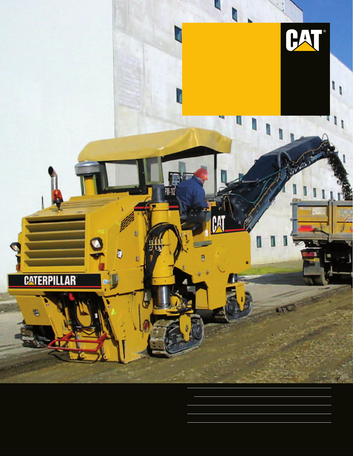
Caterpillar®3126B ATAAC Engine
Dependable, field-proven, efficient Cat power with optimized power curve for milling
applications. Engine is U.S. EPA Tier 2 and European EU Stage II compliant.
Cat diesel engine. The engine offers
outstanding value by combining
industry leading electronic capabilities,
performance and reliability with
optimum fuel economy.
Optimized power curve. Engine power
curve is optimized for milling
applications providing optimum power
while keeping the engine operating at
peak efficiency.
Turbocharged and air-to-air aftercooling
(ATAAC). High horsepower with
increased response time is assured
while keeping exhaust temperatures low
and in concert with the tight tolerance
combustion chamber components,
maximizing fuel efficiency and
minimizing emissions.
Hydraulic electronic unit injection.
This feature provides reduced engine
noise, improved fuel economy, faster
hot and/or cold starts and better high
altitude performance.
Propel System
Hydrostatic drive with hydraulic flow provided by a variable displacement axial piston
pump. Dual displacement drive motors on each track provides balanced tractive effort.
Load control system (anti-stall).
The electronically controlled system
matches propel speed to load on engine
for maximum production.
wo speed ranges.
T
1
4
2
operates at either maximum torque
throughout the entire milling speed
range or at a faster travel speed for
moving around the job site.
Positive traction control (flow divider).
Equal hydraulic oil flow to each drive
motor increases tractive effort in hard
cutting applications. The positive
traction control is actuated from the
operator’s console.
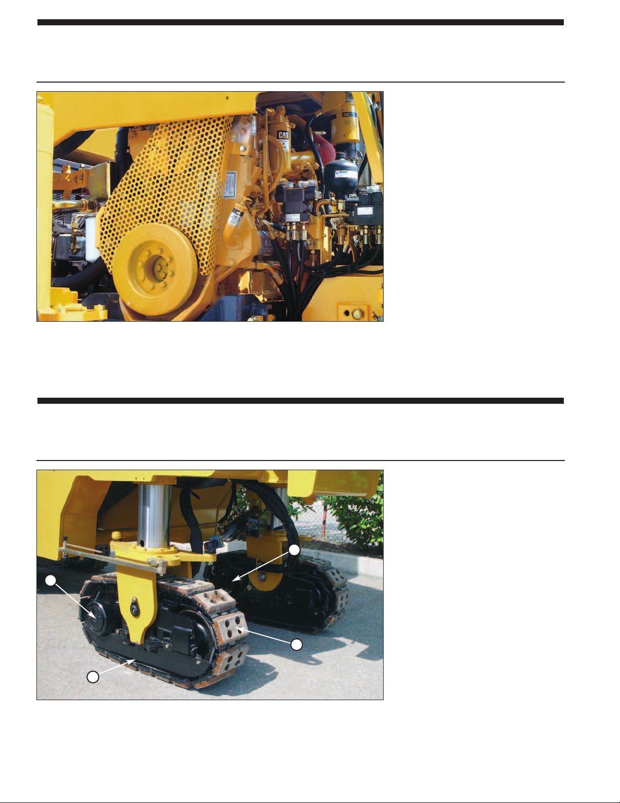
The machine
ethane track pads.Track pads in
3
1 Two Speed Drive Motor
Polyur
2
Heavy-duty Rollers
3
4 Planetary w/Secondary Brake
2
ethane T
rack Pads
Polyur
polyurethane provide long service life
and positive traction on all pavement
surfaces.
Page 3
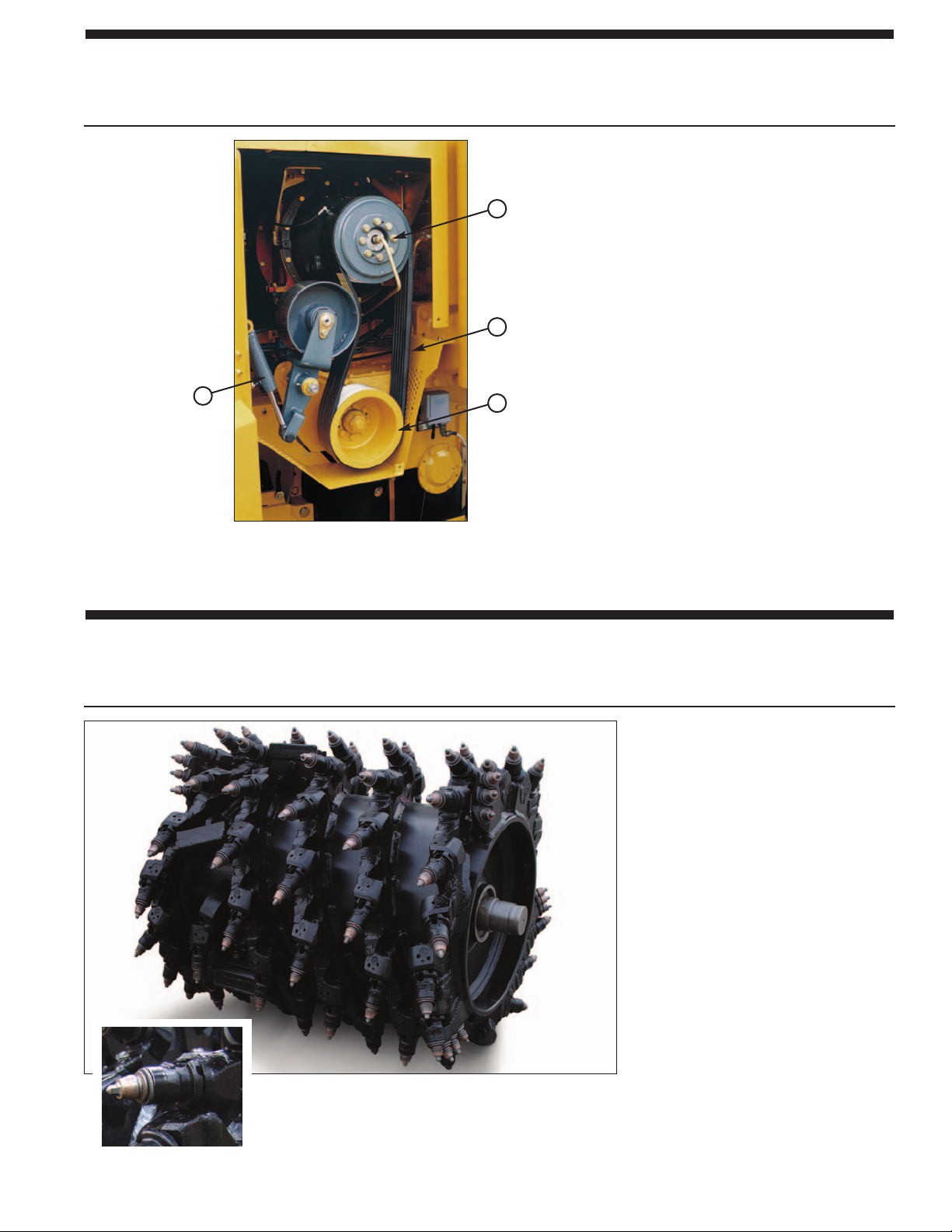
Rotor Drive
Delivers maximum available horsepower to each cutting tool.
1
2
4
3
Mechanical dry clutch. The rotor drive
consists of trapezoid pulleys, molded
high-strength belt and a hydrauliccoupling dry clutch. The field-proven
drive system delivers reliability and
long service life.
Drive train protection. A drive train
protection device protects rotor drive
system, rotor and tools by instantly
disengaging rotor drive whenever an
abrupt drop in rotor rpm occurs.
Two cutting speeds. Upper and lower
sheaves are easily interchangeable for
maximum torque with the toughest
materials and dif
requirements.
Molded six-rib high tensile belt. High
tensile belt provides efficient
transmission and long service life.
ferent material sizing
1 Upper Sheave
2 Molded Drive Belt
3 Lower Sheave
4 Tension Cylinder
Automatic belt tension adjustment. The
hydraulically powered automatic drive
belt tensioner prevents rotor drive belt
slippage and reduces maintenance.
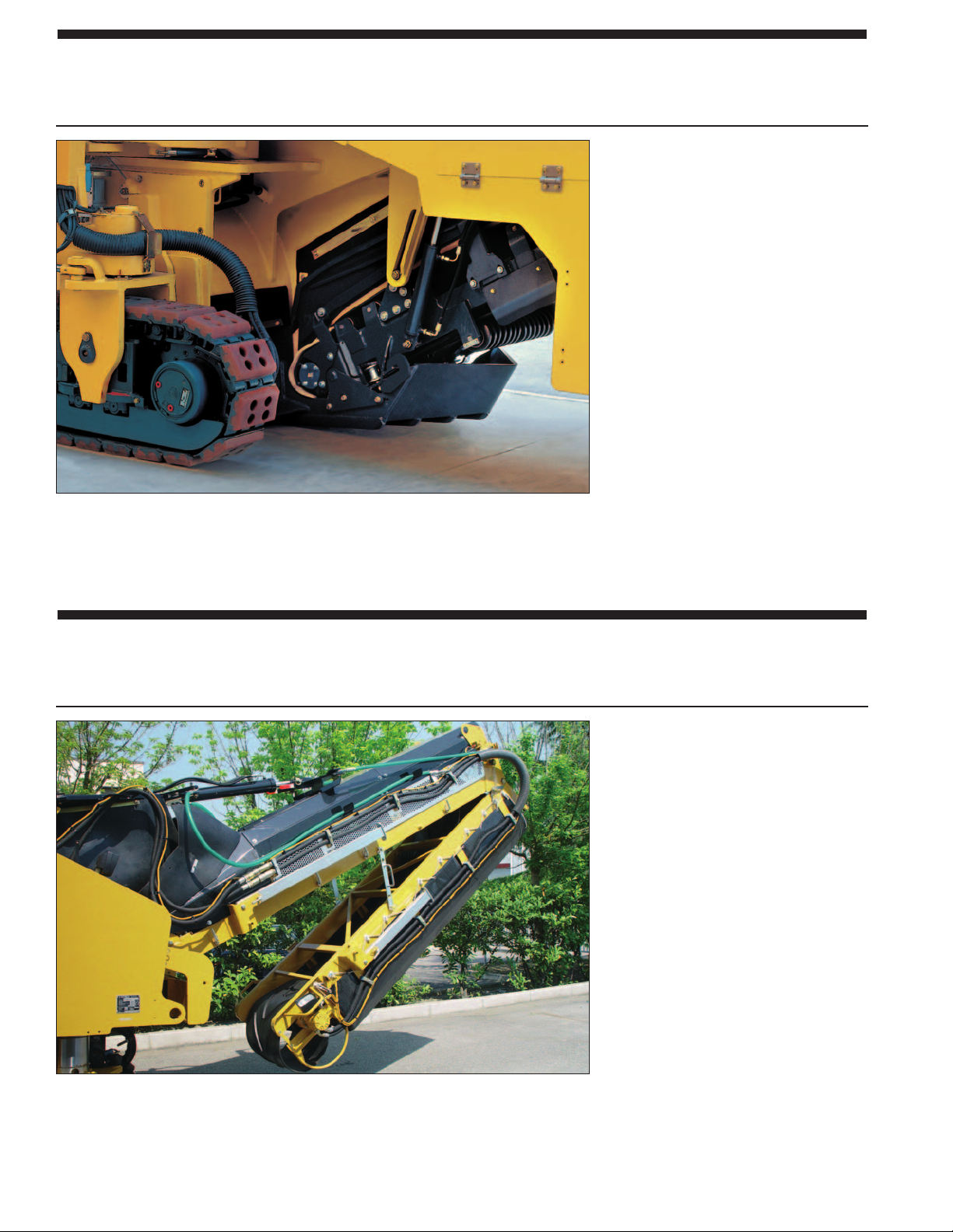
Rotor
Designed for high production and long service life. Quick release conical tool holders for
quick and easy tool replacement.
98 carbide-tipped tools. Tools are
mounted in durable three-piece, quick
release patented tool holders and
arranged in a triple wrap flighting
pattern for maximum breakout force.
Quick release conical tool holders. A
tapered fit maintains tightness in holder
base. Fast and ef
provided by the quick release conical
tool holder tool removing system.
Large replaceable carbide faced
loading paddles. Loading paddles
effectively move milled material onto
collecting conveyor resulting in higher
production and less wear on inside of
rotor chamber and cutting tools.
fortless tool removal is
Quick r
elease thr
ee-piece tool holder
Optimum tool spacing. T
placement on rotor ends provides
optimum tool spacing to clean up loose
.
material and reduces wear on drum
when maneuvering in the cut.
riple-tree tool
3
Page 4
Primary Collecting Conveyor
The collecting conveyor belt efficiently clears out the cutter box fast. Water spray system
for lubrication, cooling and dust reduction.
Optimum material sizing and gradation.
The hydraulically operated anti-slab
device prevents slabbing of the road
surface, protects the collecting
conveyor and ensures an optimum
discharge opening to the rotor chamber.
550 mm (21.6") wide collecting
conveyor. Driven by a high torque
hydraulic motor for maximum
efficiency.
Variable belt speed. The collecting
conveyor features variable belt speed
for optimum production in all
applications. Reversible belt rotation
control is also provided.
Optimum dust reduction. Standard
pressurized water spray lubricates and
controls dust on collecting belt. Water
spray nozzles are easily removed for
inspection and replacement without the
need for tools.
Folding Front Loading Conveyor
High capacity and versatility add to increased job site productivity. Conveyor can be folded
to reduce machine dimensions during transport.
Folding conveyor. Machine
transportation is made easier by the
folding front conveyor that reduces the
machine dimensions.
600 mm (23.6")
Height adjustment is hydraulically
controlled and two cylinders provide a
41 degree swing to the left and right.
Variable loading belt speed and
reversible rotation. The front loading
conveyor also includes variable belt
speed and reversible belt rotation
control. The loading belt speed is
infinitely variable and provides
optimum discharge capability for
uniformly loading the haul truck.
Simplified conveyor r
Quick-fitting hydraulics and mechanical
conveyor components allow the front
conveyor to be easily detached from the
machine.
wide upper conveyor
emoval.
.
4
Page 5

Operator’s Station
Designed for efficiency, productivity and simple operation. Easy to reach controls minimize
operator fatigue.
Ergonomic operator’s station. The full
width operator
of the front loading conveyor and side
plates for precise and rapid positioning.
Suspension seat. Durable suspension
seat with armrest provides optimum
operator comfort.
Warning horns and shut down buttons.
Located on the operator’s station and at
ground level control stations.
Hydraulically operated canopy option.
Full width canopy with two extending
side wings and front windshield and
rear window provides optimum
operator comfort and protection.
Canopy can be hydraulically lowered
during transportation.
Operating controls. The distribution and
clear instrumentation layout on the
front and side control consoles have
been designed to ensure minimum
operator effort and maximum
automation. All gauges and displays are
easily visible even in direct sunlight.
’s station provides a view
The large display provides
operating parameters for
machine and engine diagnostics.
Graphic display. A large display, easily
visible in direct sunlight, provides
operating parameters for machine and
engine diagnostics. The display presents
a single interface for service diagnostics
and calibration.
Computerized monitoring system. The
system constantly monitors system
pressures and engine condition with
multiple modes of operation.
operator if a
three levels of event information.
Standby control. A single switch control
allows the operator to engage or
disengage main operating functions
including propel, water spray system,
leveling system and conveyor rotation
for maximum automation.
problem does occur with
Alerts the
5
Page 6

Flush Cutting Feature
Full flush cutting operation with hydraulic control of the right rear leg, allows the
PM-102 to be used up close to a curb, wall or guard rail.
Flush cutting. The right rear leg can be
swung in within the machine’
width for full flush cutting applications.
With the right rear leg swung in, the
machine can cut close to a wall, barrier
Leg in the full-out position.
Leg in the swing-in position.
or other vertical obstruction.
Exclusive Caterpillar single-piece
swing-arm design.
The swing-in arm mechanism ensures
increased rigidity eliminating excessive
wear for increased component life.
Automatic control. The rear leg
swing-in system is automatic and
controlled from the operator’s station.
The operator is not required to leave the
seat while positioning the right rear leg
within the machine’s cutting width.
s cutting
Leg in the full-in position.
Steering Right Rear Track
Optimum machine handling for precise control and production.
Precise control. A microprocessor
electronically controls the steering
angle of the right rear track. The rear
track steering angle is automatically
adjusted in relation to the position of
the front tracks.
Enhanced steering ability. The
machine’
facilitates operation in confined areas
and ensures a close cut around cul-desacs or turns.
in both positions, whether positioned
within or outside the cutting width.
s rear track steering feature
The right rear track steers
6
Page 7

Automatic Grade and Slope Control Option
The optional grade controls provide precise control of rotor to a preset cutting depth.
System can be configured to control grade or cross slope.
Contacting wire rope grade sensors.
ire rope grade sensor measures side
W
plate movement that enables the entire
1
2
length of the side plate to become an
averaging device for extremely accurate
grade matching. Cross slope sensor
adds to system versatility.
Leveling control boxes. Two control
boxes located at the operator’s station
allow manual or automatic leveling
adjustment. Constant read-out for rotor
depth and cross slope are displayed on
each control box and is easily visible
even in direct sunlight or low light
conditions.
1 Contacting Grade Sensor
2 Leveling Control Boxes
Reliability and Serviceability
Reliability and serviceability are integrated into every Caterpillar machine. These
important features keep your machine investment profitable.
Large service doors. Large service
doors provide access to engine and
hydraulic components. Engine side
covers swing wide to allow ground
level access to engine. Rear cover
swings up for access to radiator and oil
cooler.
Hydraulic r
service door opens wide for easy access
to rotor for inspection and tool
maintenance.
Electronic Control Module (ECM).
The ECM monitors machine systems
and provides self-diagnostics for
operator or service personnel.
otor ser
vice door
.
The rotor
All-weather connectors. Nylon braided
wrap ensure electrical system integrity
isual indicators.Visual indicators
V
allow easy check of water spray tank
level and hydraulic oil tank level.
.
7
Page 8

Engine
The Caterpillar®3126B engine is a six
cylinder, turbocharged air-to-air
after-cooled diesel engine. The engine
meets U.S. EPA Tier 2 and European
EU Stage II engine emission
regulations.
Engine Cat®3126B
Gross Power kW hp
SAE J1995 168 225
Net Power kW hp
ISO 9249 156 209
EEC 80/1269 156 209
SAE J1349 151 203
Specifications
Bore 110 mm 4.3"
Stroke 127 mm 5.0"
Displacement 7.2 liters 442 in
n
The power ratings apply at a rated
speed of 2200 RPM when tested
under the reference conditions for the
specific standard.
n
The net power advertised is the
power available at the flywheel when
the engine is equipped with an
alternator, air cleaner, muffler and
fan.
n
Derating is not required up to an
altitude of 3000 m (9850').
n
Cold mode starting aid, dual fuel
filters with water separator and air
compressor are standard.
Propel System
Hydrostatic drive with hydraulic flow
provided by a variable displacement
piston-type pump. Drive motors with
planetary gear reduction on each track
or wheel provides balanced tractive
effort. Machine can be equipped with
either a track or wheeled undercarriage.
es
Featur
n
A variable displacement, piston-type
pump with electronic displacement
control supplies pressurized flow.
n
Positive traction control valve
provides equal hydraulic oil flow to
each drive motor to increase tractive
effort in hard cutting.
n
3
Drive motors have two swashplate
positions allowing operation at either
maximum torque throughout the
entire milling speed range or at a
faster travel speed for moving around
the job site.
n
Gear selection controlled electrically
by a two-position switch on the
operator’s console.
n
Infinitely variable machine speed and
direction of travel controlled by
propel lever and speed dial.
n
Load control system, controlled by
Electronic Control Module (ECM),
matches propel speed to load on the
engine for maximum production.
n
Track undercarriage – tracks are
720 mm (28.3") long, 225 mm (8.8")
wide and feature replaceable
polyurethane track pads.
n
Wheel undercarriage – wheels have a
diameter of 660 mm (25.9") and are
260 mm (10.2") wide.
Rotor Drive System
Operates direct through a hydraulically
actuated, dry clutch driving a planetary
gear reducer.
Features
n
Heavy-duty dry clutch mounts
directly to the engine.
actuated by a ON/OFF switch on the
operator’s console.
n
Mechanical dry clutch consists of
trapezoid pulleys, molded highstrength belt and a hydraulic-coupling
dry clutch. The field-proven drive
system delivers reliability and long
service life.
n
A drive train protection device
protects rotor drive system, rotor and
tools by instantly disengaging rotor
drive whenever an abrupt drop in
rotor rpm occurs.
n
Molded six-rib high tensile strength
drive belt drives the rotor through a
drum drive gear reducer located
inside the rotor mandrel.
n
Hydraulically powered automatic
drive belt tensioner prevents rotor
drive belt slippage and reduces
maintenance.
n
Upper and lower sheaves are easily
interchangeable for maximum torque
with the toughest materials and
different material sizing
requirements.
Rotor Speed:
@ 2200 engine rpm 118 rpm
Hydraulically
Max. Speeds (forward and reverse):
Track undercarriage
Operating 27 mpm - 89 fpm
Travel 4.1 km/h - 2.5 mph
Wheel undercarriage
Operating 46 mpm - 151 fpm
ravel
T
8
PM-102 specifications
6.4 km/h - 3.9 mph
Page 9

Rotor Housing
n
Rotor housing is made with hi-grade
anti-wear material for long service
life.
n
Large discharge opening clears out
the rotor housing fast for increased
production and reduced tool wear.
n
Side plate contact surfaces features
wear-resistant materials for reduced
wear and longer service life.
n
Floating moldboard with adjustable
down pressure is standard.
n
Height control for rotor door located
at operator’s station and at two
ground level control stations.
Steering
Hydraulic power-assist steering with
steering wheel on operator’s console.
Features
n
Double-acting steering cylinders
control the front and right rear tracks.
n
Steering of the right rear track is
electronically controlled with angle
adjusted in relation to the position of
the front tracks.
urning Radius (to the right):
T
Track undercarriage 3.45 m (11' 3")
Wheel undercarriage 2.10 m (6' 8")
Hydraulic System
n
Pumps for propel, collecting and
upper conveyors, auxiliary hydraulics
and cooling fan are installed on the
engine mounting pad.
n
Hydraulic oil cooler located at the
rear of the machine is designed for
ficient cooling and easy access for
ef
cleaning.
n
Three-micron filtration on pressure
side of auxiliary flow and sevenmicron filtration on return side.
n
Quick-connect hydraulic test ports
simplify system diagnostics.
Conveyor System
n
Collecting conveyor is driven by a
high torque hydraulic motor to ensure
maximum production and clearing
out the rotor housing effectively.
n
Variable belt speed control for
collecting and front loading
conveyors controls loading of milled
materials to closely match material
type and amount.
n
Both conveyor belts can be reversed
for quick clean out.
n
Folding front loading conveyor
facilitates machine transportation.
Collecting Conveyor
Width 550 mm 21.6"
Speed 252 mpm 827 fpm
Upper Conveyor
Length 6.3 m 20' 6"
Width 600 mm 23.6"
Speed 252 mpm 827 fpm
Swing (from center)
41 degrees
Water Spray System
n
Centrifugal pump supplies water to
spray nozzles for dust control and
belt lubrication.
n
Water spray nozzles focuses the
water spray in a flat fan pattern to the
rotor for better cooling of cutting
tools.
n
Nozzles are easily removed for
inspection and replacement without
the need for tools.
n
Standard system includes gauges to
monitor water pressure, a low water
level indicator and water control
valves to conserve water usage.
n
Water tank can be filled from the top
of the machine or at ground level.
Brakes
Primary Brake Features
n
Closed-loop hydrostatic drive
provides dynamic braking during
normal operation.
Parking Brake Features
n
Spring-applied/hydraulically-released
multiple disc type brake mounted on
each gear reducer. Brakes are applied
automatically when propel lever is in
the neutral detent position.
n
Secondary brakes are activated by a
button on the operator’s console, loss
of hydraulic pressure in the brake
circuit or when the engine is shut
down.
n
Propel pump is destroked when
parking brake is engaged. Propel
lever must be returned to neutral after
brake is released before machine will
propel.
PM-102 specifications
9
Page 10

Service Refill Capacities
Liters Gallons
Fuel tank 400 105
Cooling system 35 9.3
Engine oil w/filter 31 8.1
Propel planetary
gear reducer (each) 0.9 0.24
Hydraulic tank
Water spray system 1060 280
110 29
Electrical
The 24-volt electrical system consists
of two maintenance-free Cat batteries.
Electrical wiring is color-coded,
numbered and labeled with component
identifiers.
750 cold cranking amps (cca). The
system includes a 65-amp alternator
The starting system provides
.
Frame
Fabricated from heavy gauge steel
plates and structural steel tubing. Track
assembly features track frame stops to
limit track angles to improve machine’s
ability to propel out of deep cuts.
of deck and steps features non-skid
treads for sure footing.
Top
Rotor Specifications
n
Tools are mounted in durable threepiece, quick release tool holders.
n
Holders feature a tapered fit to
maintain tightness in holder base.
n
The quick release tool holders allow
fast and easy replacement of tools.
n
ge replaceable carbide faced
Lar
loading paddles effectively moves
milled materials onto collecting
conveyor resulting in increased
production.
Rotor
Cutting width 1000 mm 40"
Cutting depth 305 mm 12"
Number of tools 98
Tool spacing (tip) 15 mm 0.6"
Grade and Slope Control
Machine elevation – rotor depth and cross slope controlled manually by operator is
standard. Automatic rotor depth and slope control is optional and features electronic
over hydraulic control. Slope sensor adds versatility.
Features
n
Machine elevation controls located on the operator
cross slope to be controlled manually
n
The optional AUTOMATIC grade and slope control automatically controls rotor
depth and cross slope to a preset cutting depth. Setting cutting depth is easily
accomplished first in manual mode by using the adjustment knob on the controller
n
Wire rope contacting grade sensor measures side plate movement that enables the
entire length of the side plate to become a mini averaging ski for optimum grade
matching.
. Visual depth gauge displays depth of cut.
’s console allows rotor depth and
Optional Equipment
Note: Some options listed may be an option in some areas and standard in others. Consult your dealer for specifics.
Automatic Grade and Slope System.
Automatically controls rotor depth and
cross slope to a preset cutting depth.
Contacting wire rope grade sensor
measures side plate movement that
enables the entire length of the side plate
to become a mini averaging ski for
optimum grade matching. System also
includes a cross slope sensor to meet
slope applications/requirements in job
specifications.
Hydraulically Operated Canopy. Full
width canopy with two side extending
wings and front and rear windshields
provides optimum operator comfort and
protection. Canopy can be hydraulically
lowered for transportation.
High Pr
system uses water from the water spray
system tank to help with machine cleanup at the end of each day’
System includes a spray wand and hose
with a quick-connect coupler.
essure Washdown System.
s operation.
This
Water Tank High Capacity Refilling
A hydraulically driven water
Pump.
pump provides fast water tank refilling.
Roading Light Package. Front and
-facing headlights with directional
rear
indicators. Light package used for
highway transport purposes only
.
.
10
PM-102 specifications
Page 11

Dimensions
R
PM-
PM-110202
Operating
A Overall length (conveyor up) 10.7 m 35' 1"
B Overall machine width (right rear leg in)
Track undercarriage 1.98 m 6' 5"
Wheel undercarriage
C Maximum height (canopy raised) 3.4 m 11' 2"
Minimum height 2.38 m 7' 8"
D
E Maximum truck clearance 4.8 m 15' 7"
Conveyor swing 41 degrees left or right of center
Collecting conveyor width 550 mm 21.6"
Upper conveyor width 600 mm 23.6"
Inside turning radius
Track undercarriage 3.45 m 11' 3"
Wheel undercarriage 2.10 m 6' 8"
Shipping
F Length of base machine 5.33 m 17' 5"
G Length (conveyor folded) 8.5 m 27' 8"
H Height (conveyor folded) 3.1 m 10' 1"
I Height (canopy folded) 3.1 m 10' 1"
J Maximum width
Track undercarriage 2.5 m 8' 2"
Wheel undercarriage 2.4 m 7' 9"
2.0 m 6' 6"
E
C
I
H
D
G
A
B
J
F
Weights
Operating Weights
Track undercarriage 17 600 kg 38,810 lb
Wheel undercarriage
17 100 kg
Weights shown are approximate and include coolant, lubricants, full fuel tank, full water tank and a 75 kg (165 lb) operator.
37,705 lb
Shipping Weights
Track undercarriage
Wheel undercarriage
Weights shown are approximate and include coolant, lubricants, 50% fuel level and empty water tank.
17 100 kg
16 400 kg
37,705 lb
36,160 lb
PM-102 specifications
11
Page 12

Caterpillar offers a comprehensive line of profilers.
The PM-200 and PM-201 are designed to have the best productivity, reliability, versatility,
visibility and ease of operation in their class.
Contact your local Caterpillar dealer to learn more about the complete line of Caterpillar Paving Products.
PM-200
Operating
Gross Power (SAE J1995) 429 kW 575 hp
Cutting Width 2010 mm 79"
Cutting Depth 320 mm 12.6"
Propel Speeds
Rotor Drive Two six-rib high tensile belts
Weight 30 900 kg 68,135 lb
Operating 38 mpm 125 fpm
Travel 5.9 km/h 3.6 mph
Clutch Hydraulic/wet multi-disc
PM-201
Operating Weight 39 165 kg 86,360 lb
Gross Power 485 kW 650 hp
Cutting Width 2100 mm 83"
Cutting Depth 305 mm 12"
Propel Speeds
Operating 40 mpm 132 fpm
Travel 6.0 km/h 3.7 mph
Rotor Drive Eleven-rib high tensile belt
Clutch Hydraulic/wet multi-disc
QEHQ1169 (06/05)
© 2005 Caterpillar
All Rights Reser
www
ed machines in photography may include optional equipment.
Featur
Materials and specifications are subject to change without notice.
ved.
.cat.com.
 Loading...