How it Works
Log In / Sign Up
Buy Points
How it Works
FAQ
Contact Us
Questions and Suggestions
Users
Miele
Loading...
P
PG8056208V
2
PG8056240V
4
PG8056U240
2
PG8056UAE208V
2
PG8061240V
4
PG8061UAE208V
3
PG8061UAE240V
Pg8080BW
PG8080I240
PG8083SCVI120V
6
PG8083SCVI240V
6
PG8130I240V
2
PG8132SCIXXL
2
PG8133SCVI240V
PG 8504
41
PG 8527
38
PG 8527 D
7
PG 8527 EL
15
PG 8527 EL AV
2
PG 8528
40
PG 8528 D
7
PG 8528 EL
16
PG 8535
24
PG 8535 OXIVARIO
12
PG 8536
30
PG 8536 LFM
PG 8536 OXIVARIO
PG 8536 RU
PG 8562
7
PG 8581
39
PG 8582
43
PG 8582 CD
39
PG 8583
50
PG 8583 CD
44
PG 8591
34
PG 8592
42
PG 8593
48
PG 8595
2
PG 8596
PG 8597
2
PG 8821
3
PG 8822
5
PG 8825
5
PG 8830
4
PG8922
2
PG8930
2
PIB 100
21
PLATINUM
2
Platinum Plus
3
Plus G686
PLW 6011
33
PLW 6111
35
PLW 8505
2
PLW 8615
27
PLW 8616
26
PLW 8617
25
PM 1210
64
PM1214
66
PM 1217
66
PM 1318
28
PM 1318 EL
9
PM 1318 G
6
PM 1318 G L
PM 1318 G L-GE
PM 1418
30
PM 1418 EL
7
PM 1418 G
6
PM 1418 G L
PM 1418 G L-GE
PM 1421
30
PM 1421 EL
8
PM 1421 G
6
PM 1421 G L
PM 1421 G L-GE
PM 1621
17
PM 1625
17
PM 1630
17
PM 1635
17
PM 1825
17
PM 1830
17
PM 1835
17
POIGNE
Polaris
PowerLine Complete C3 Allergy SGFF5
Prasek
Preformance 1600
Premier
Premier 300
Premier 3000
Premier 520
2
PREMIER NOVO
2
PREMIER NOVO W842
Premier Plus
2
Premier W 500
Premier W520
Premier W522
PRESTIGE
Prestige Plus
Prestige Plus 6
2
PRI 210
5
Loading...
Loading...
Nothing found
PLW 6011
Installációs terv [hu]
19 pgs
515.35 Kb
0
Installatietekening [nl]
19 pgs
514.08 Kb
0
Installation diagram
17 pgs
513.03 Kb
0
Installation diagram [cs]
19 pgs
515.9 Kb
0
Installation diagram [de]
19 pgs
516.54 Kb
0
Installation form [no]
19 pgs
513.8 Kb
0
Installation Manual [zh]
64 pgs
2.43 Mb
0
Installation plan [el]
19 pgs
518.67 Kb
0
installation plan [es]
18 pgs
513.63 Kb
0
Installation Plan [hr]
19 pgs
514.99 Kb
0
Installation plan [sl]
19 pgs
514.19 Kb
0
Installation Plan [tr]
18 pgs
512.34 Kb
0
Instructions Manual
64 pgs
1.75 Mb
0
Instructions Manual [bg]
64 pgs
1.78 Mb
0
Instructions Manual [el]
64 pgs
1.79 Mb
0
Instructions Manual [ro]
60 pgs
1.75 Mb
0
Instructions Manual [sl]
64 pgs
1.75 Mb
0
Operating instructions
60 pgs
1.72 Mb
0
Plan de instalare [ro]
19 pgs
514.95 Kb
0
User manual
60 pgs
1.74 Mb
0
User manual
60 pgs
1.74 Mb
0
User manual
60 pgs
1.7 Mb
0
User manual
60 pgs
1.74 Mb
0
User manual
60 pgs
1.74 Mb
0
User manual [cs]
60 pgs
1.76 Mb
0
User manual [de]
60 pgs
1.74 Mb
0
User manual [hr]
60 pgs
1.76 Mb
0
User manual [hu]
60 pgs
1.8 Mb
0
User Manual [nl]
60 pgs
1.74 Mb
0
User manual [no]
60 pgs
1.74 Mb
0
User manual [pt]
60 pgs
1.75 Mb
0
User Manual [ru]
68 pgs
1.9 Mb
0
User manual [tr]
60 pgs
1.77 Mb
0
Table of contents
Loading...
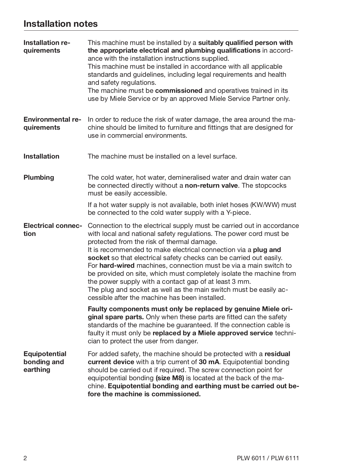
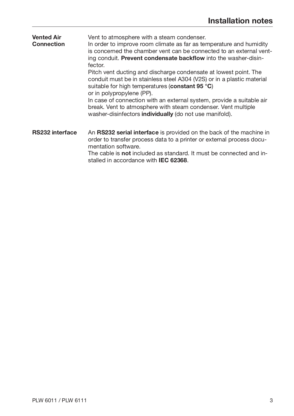
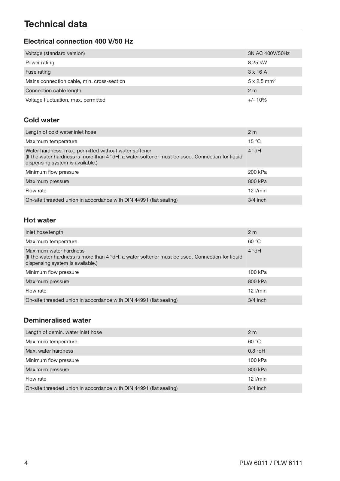
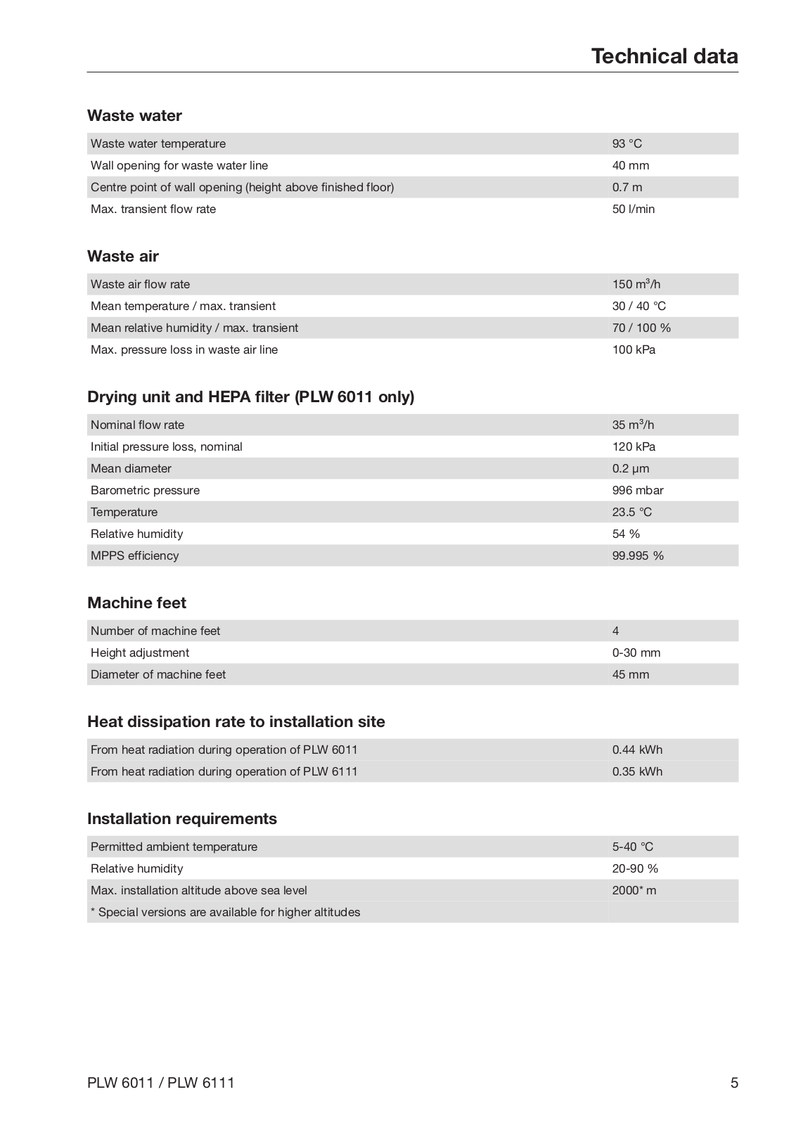
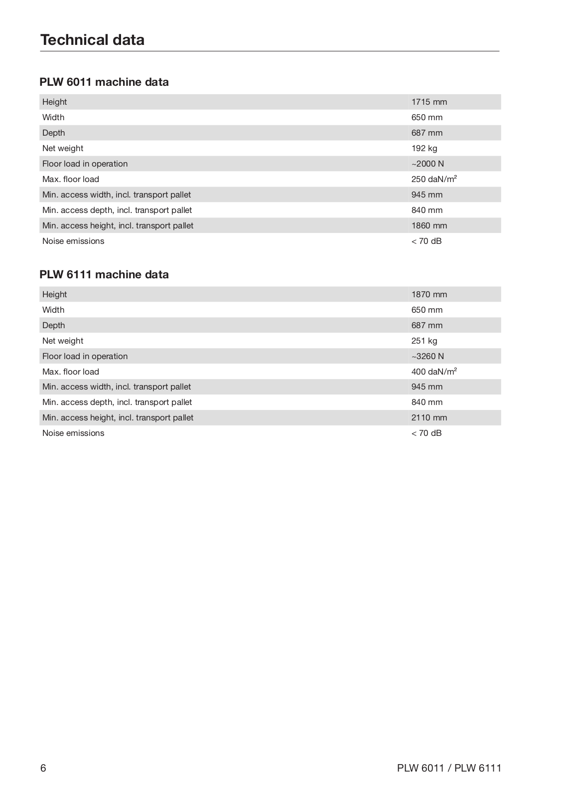
Miele PLW 6011, PLW 6111 Installation diagram
...
Miele Installation diagram
Download
Specifications and Main Features
Frequently Asked Questions
User Manual
Download
Page 1
Page 2
Page 3
Page 4
Page 5
Page 6
Page 7
Page 8
Page 9
Page 10
Page 11
Page 12
Page 13
Page 14
Page 15
Page 16
Page 17
Loading...
+
hidden pages
Unhide
You need points to download manuals.
1 point = 1 manual.
You can buy points or you can get point for every manual you upload.
Buy points
Upload your manuals