

Installation plan
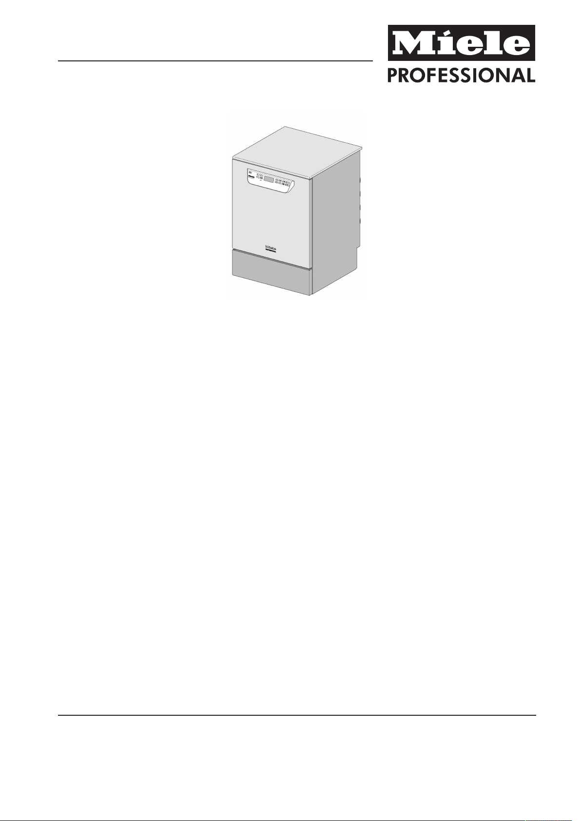
PG 8591
PG 8592
PG 8593
It is essential to read the operating instructions
and service documents before installation or use
of this appliance. This will prevent both personal
injury and damage to the machine.
en - AU, NZ
M.-Nr. 11 196 260

Installation notes
Installation
requirements
Surrounding area
Preventing a
build-up of heat
This machine must be connected to the mains supply, and plumbed
in, in accordance with the installation instructions provided.
Installation must only be carried out by authorised installers in
accordance with valid regulations, relevant standards and health and
safety codes.
The machine must be commissioned and operators trained in its use
by Miele Service or by an approved Miele Service Dealer only.
Condensate can build up in the area surrounding the machine. Any
cabinetry and fixtures in the room must be suitable. If the machine is
installed under a countertop (built-under model), the protective foil
supplied must be stuck to the underside of the worktop and a
stainless steel panel must be installed above the door opening to
provide protection from the steam. The stainless steel panel can be
ordered from Miele.
During the active drying process (TA) there is a risk of heat building
up. A build-up of heat at the back of the machine can cause the
machine casing and electronic components to overheat. A build-of
heat can also cause condensate to settle on adjoining surfaces. This
can lead to a reduced machine lifespan and cause damage to
surrounding units and worktops.
Cooling the
exhaust air
Plumbing
– To prevent a build-up of heat, ensure that there is sufficient space
for air to circulate behind base units.
– Leave a minimum safety gap of 10mm for air flow between a
built-under machine and the worktop above it.
– Do not seal any gaps between base units or between base units
and the machine.
– If necessary, fit ventilation grilles in adjoining units and in the
worktop.
Activate “Air cooling” if ambient room temperature exceeds 30°C.
This option is found in the System settings menu under “Further
settings”.
The cold water, hot water, demineralised water and drain water can
be connected directly without a non-return valve. Use the Y-piece
supplied to connect the inlet hoses to the machine (KW) and to the
steam condenser (DK). Alternatively, you may also install an
additional cold water supply and connect the steam condenser to this
supply.
If access to a hot water supply is not available, a Y-piece must be
used to connect both inlet hoses (KW cold water and WW hot water)
to the cold water supply.
The stopcocks must be easily accessible.
Electrical
connection
2 PG 8591 / PG 8592 / PG 8593
Connection to the electrical supply must be carried out in accordance
with local and national safety regulations. The power cord must be
protected from the risk of thermal damage.
It is recommended to make electrical connection via a plug and

Installation notes
socket so that electrical safety checks can be carried out easily.
For hard-wired machines, connection must be via a main switch to
be provided on site, which must completely isolate the machine from
the power supply with a contact gap of at least 3mm.
The plug and socket as well as the main switch must be easily
accessible after the machine has been installed.
Equipotential
bonding and
earthing
Liquid media:
position of
external
containers
Communication
modules
For added safety the machine should be protected with a residual
current device with trip current of 30mA.
Equipotential bonding should be carried out if required. A screw
connection for equipotential bonding is provided at the back of the
machine. Equipotential bonding and earthing must be completed
before the machine is commissioned.
The liquid agent container for external dispensing must be placed
next to or underneath the machine. Place the container next to the
machine on the floor or in an adjacent cabinet. Do not position the
container above the machine. The dispenser hose must not be kinked
or trapped.
Ethernet and RS232 modules are available as optional extras. They
are not supplied with the machine. The connection box for these
should be installed near the machine for transferring and printing
process data. These must be installed and connected in accordance
with IEC 60950.
PG 8591 / PG 8592 / PG 8593 3

Illustrations
KW Cold water connection EL Electrical connection
WW Hot water connection DK Cold water connection, steam condenser
VE Demineralised water connection DS Dispenser system
AW Drain connection NW Network and printer connection (optional)
PA Equipotential bonding
4 PG 8591 / PG 8592 / PG 8593

Illustrations
KW Cold water connection EL Electrical connection
WW Hot water connection DK Cold water connection, steam condenser
VE Demineralised water connection DS Dispenser system
AW Drain connection NW Network and printer connection (optional)
PA Equipotential bonding
PG 8591 / PG 8592 / PG 8593 5

Illustrations
Machine versions
PG 8591-93 Undercounter PG 8591-93 Freestanding
6 PG 8591 / PG 8592 / PG 8593

Technical data
Electrical connection
Voltage (3 phase version) 3N AC 400/50
Total connected load 9.3kW
Fuse rating 3 x 15-16A
Connection cable, cross-section min. 5 x 2.5mm²
Length of mains connection cable (H05(07)RN-F) 1.8m
Voltage (singel phase version) AC 230/50
Total connected load 6.3kW
Fuse rating 1 x 30-32A
Connection cable, cross-section min. 3 x 4mm²
Length of mains connection cable (H05(07)RN-F) 1.9m
Cold water connection
Maximum incoming temperature 20°C
Max. water hardness 12.6mmol/l
70°dH
Recommended flow pressure: 200kPa
Minimum flow pressure with extended water intake 100kPa
Maximum pressure 1000kPa
Flow rate 7.5l/min
On-site threaded union in accordance with DIN 44991 (flat sealing) 3/4Inch
Length of cold water inlet hose 1.7m
Length of steam condenser inlet hose 1.7m
Hot water
Maximum incoming temperature 60°C
Max. water hardness 12.6mmol/l
70°dH
Recommended flow pressure: 200kPa
Minimum flow pressure with extended water intake 100kPa
Maximum pressure 1000kPa
Flow rate 7.5l/min
On-site threaded union in accordance with DIN 44991 (flat sealing) 3/4Inch
Length of hot water inlet hose 1.7m
PG 8591 / PG 8592 / PG 8593 7

Technical data
Demin. water
Maximum incoming temperature 60°C
Recommended flow pressure (DI pressure-resistant) 200kPa
Minimum flow pressure with extended water intake 100kPa
Maximum pressure (AD pressure resistant) 1000kPa
Flow rate 7.5l/min
On-site threaded union in accordance with DIN 44991 (flat sealing) 3/4Inch
Length of demin. water inlet hose 1.7m
Waste water
Drainage temperature 93°C
Drain hose length, standard 1.4m
Drain hose, max. drainage length 4.0m
Max. drain pump head height from bottom edge of machine 1.0m
Max. transient flow rate 16l/min
On-site sleeve for drain hose (dia. x length) 22 x 30mm
Machine feet
Height-adjustable machine feet 0 - 60mm
Diameter of machine feet 35mm
Insert for machine foot, size of thread M 8
Machine data
Building-under height 820mm
Height including lid 835mm
Width 598mm
Depth 598mm
Door height 622mm
Net weight 78kg
Floor load in operation 1,200N
Min. access width, incl. transport pallet 670mm
Min. access depth incl. transport pallet 740mm
Min. access height, incl. transport pallet 920mm
Noise level in dB (A),
sound pressure LpA during cleaning and drying phases
< 70dB
8 PG 8591 / PG 8592 / PG 8593

Technical data
Heat dissipation rate to installation site
From heat radiation during operation 0.35kWh
From load whilst unloading 0.40kWh
Installation requirements
Permissible ambient temperature 5 - 40°C
Max. relative humidity up to 31°C 80%
Rel. humidity, declining proportionally up to 40°C 50%
Max. installation altitude above sea level 1,500m
PG 8591 / PG 8592 / PG 8593 9

Miele & Cie. KG
Carl-Miele-Straße 29
33332 Gütersloh
Germany
Telefon: 05241 89-0
Telefax: 05241 89-2090
Internet: www.miele.com/professional
Alteration rights reserved / Publication date: 2018-11-05 M.-Nr. 11 196 260 / 00
PG 8591
PG 8592
PG 8593
 Loading...