

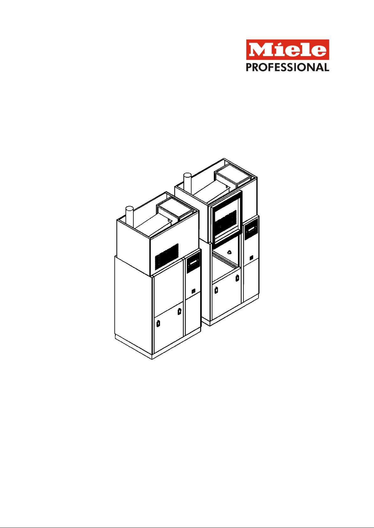
Installation plan
PG 8528 D/EL
Mat. no.
06812184
Version 05
Installation Plan PG 8528 D/EL
Version: 01/07/2016 Page 1
Labwasher
PG 8528
connection
(DU/S)
Voltage
3 AC 208/60
V/Hz
3 AC 208/60
V/Hz
Connected load
2.1 kW
2.1 kW
Fuse rating
3 x 15 A
3 x 15 A
Connecting cable, minimum cross-section
4 x 12 AWG
4 x 12 AWG
(DU/E)
Voltage
3 AC 208/60
V/Hz
3 AC 208/60
V/Hz
Connected load
9.0 kW
9.0 kW
Fuse rating
3 x 30 A
3 x 30 A
Connecting cable, minimum cross-section
4 x 10 AWG
4 x 10 AWG
3. Type of heating: Steam/electric switchable
Voltage
3 AC 208/60
V/Hz
3 AC 208/60
V/Hz
Connected load
21 kW
21 kW
Fuse rating
3 x 60 A
3 x 60 A
Connecting cable, minimum cross-section
4 x 6 AWG
4 x 6 AWG
Connecting cable, minimum length
from upper edge of top panelling in installations
from the ceiling
13 ft.
4.0 m
above top of floor in installations from the floor
5 ft.
1.5 m
e.g. during repair or maintenance.
The plug connection must be accessible after the
installation of the machine.
Connect the device in phase with the clockwise field
of rotation.
The installations must comply with the CAT II
installation category.
Permissible maximum voltage fluctuations
Technical Data Sheet
Type of heating:
Steam/Electric
Legend:
Notes on supply connections:
Cold, hot, DI water, high pressure steam, condensate, and compressed air may be connected
from the ceiling (standard installation) or from the floor (alternative installation). A mixed
installation of these media is possible.
Electrical
2. Type of heating: Steam with electric drying unit
Circled bold-type abbreviations mean:
Connection required
Abbreviations in dashed circles mean:
Connection optional or required for a specific model
1. Type of heating: Steam with steam drying unit
EN
We recommend connecting the appliance via a plug
so that an electrical safety check can be carried out,
+/- 10%
Installation Plan PG 8528 D/EL
Version: 01/07/2016 Page 2
conductor
Equipotential bonding and grounding must be
Ethernet interface (for transmission)
Length of connecting cable, incl. RJ45 plug (scope of
delivery)
16.5 ft.
5.0 m
The user must install an RJ45 socket above the
machine.
Or:
Serial interface (for output on HPGL-compatible printer):
Length of connecting cable, incl. RS232 plug (scope of
delivery)
16.5 ft.
5.0 m
The user must install an RS232 socket above the
machine.
The connections/installations must be designed according
to IEC 60950.
Maximum cont act current capacity:
TA OPERATION
Contact is closed during drying block
200-240/1/50-60 V/A/Hz
PRG RUNS
Contact is closed during rinsing, drying and cooling return
time.
200-240/1/50-60 V/A/Hz
OPERATION
Contact is closed while machine is switched on
200-240/1/50-60 V/A/Hz
MALFUNCTION
Contact is closed if there is a malfunction
200-240/1/50-60 V/A/Hz
PRG END
Contact is closed between program end and door opening.
200-240/1/50-60 V/A/Hz
PAUSE M.
RINSE
Contact is closed during "Pause with rinse" program
segment.
200-240/1/50-60 V/A/Hz
DRAIN STD
Contact is closed during Draining - Standard
200-240/1/50-60 V/A/Hz
DRAIN RECY.
Contact is closed during Draining - Recycling
200-240/1/50-60 V/A/Hz
User-defined
Contact is activated during water outflow, as long as
"External contact" in the block is set to "Water outflow".
200-240/1/50-60 V/A/Hz
COLD
Contact is closed during "Cold" water intake.
200-240/1/50-60 V/A/Hz
WARM
Contact is closed during "Warm" water intake.
200-240/1/50-60 V/A/Hz
AD COLD
Contact is closed during "AD Cold" water intake.
200-240/1/50-60 V/A/Hz
AD WARM
Contact is closed during "AD Warm" water intake.
200-240/1/50-60 V/A/Hz
Cold delayed
Depending on the parameter
200-240/1/50-60 V/A/Hz
Hot delayed
"switch-off delay valve", outflow will be:
200-240/1/50-60 V/A/Hz
DI-cold delayed
a. delayed (start of water inflow)
200-240/1/50-60 V/A/Hz
DI-hot delayed
b. advanced (end of water inflow)
200-240/1/50-60 V/A/Hz
DOS1-EXTERN
Activation signal for external metering pump 1
200-240/1/50-60 V/A/Hz
DOS2-EXTERN
Activation signal for external metering pump 2
200-240/1/50-60 V/A/Hz
DOS3-EXTERN
Activation signal for external metering pump 3
200-240/1/50-60 V/A/Hz
DOS4EXTERNAL
Activation signal for external metering pump 4
200-240/1/50-60 V/A/Hz
DOS5EXTERNAL
Activation signal for external metering pump 5
200-240/1/50-60 V/A/Hz
DOS6EXTERNAL
Activation signal for external metering pump 6
200-240/1/50-60 V/A/Hz
DOS7EXTERNAL
Activation signal for external m etering pum p 7
200-240/1/50-60 V/A/Hz
DOS8EXTERNAL
Activation signal for external metering pump 8
200-240/1/50-60 V/A/Hz
DOS9EXTERNAL
Activation signal for external metering pump 9
200-240/1/50-60 V/A/Hz
Message DOS 1
Contact is established when the corresponding pump is
activated during the program.
200-240/1/50-60 V/A/Hz
Equipotential
bonding and
equipment
grounding
Network and
printer connection
Connection
module
Outputs
Connection to the electrical supply must be carried
out in accordance with local and national safety
regulations.
External threaded pin with washers and nut at the
machine end, size
connected.
The following interfaces for the transmission or printing of
process data are provided at the machine:
Floating contacts (normally open contacts):
A maximum of 9 contacts may be set, possible assignment:
M 8 M 8
Installation Plan PG 8528 D/EL
Version: 01/07/2016 Page 3
Message DOS 2
Contact is established when the corresponding pump is
activated during the program.
200-240/1/50-60 V/A/Hz
Message DOS 3
Contact is established when the corresponding pump is
activated during the program.
200-240/1/50-60 V/A/Hz
Message DOS 4
Contact is established when the corresponding pump is
activated during the program.
200-240/1/50-60 V/A/Hz
Message DOS 5
Contact is established when the corresponding pump is
200-240/1/50-60 V/A/Hz
Control voltage
SLA HZG
Peak load shut-down, steam and/or electric heater
200-240/50-60 V/Hz
DOS-EXT
Filling level of external DOS containers
200-240/50-60 V/Hz
MEDIUM
Medium dispensing activated, signal for flow and volume
control
200-240/50-60 V/Hz
EXT-TEXT
External text
200-240/50-60 V/Hz
Cold water
Temperature, max.
158°F
70°C
Max. temperature when cooling the steam condenser with
cold water
68 °F
20°C
Max. water hardness
4 gpg
4°dH
Minimum flow pressure
29 psi
200 kPa
Maximum pressure
145 psi
1,000 kPa
Volume flow
4 gal/min
15 l/min
User's connection thread according to DIN 44 991 (flat
3/4" male hose
3/4" male hose
Temperature, max.
158°F
70°C
Max. water hardness
4 gpg
4°dH
Minimum flow pressure
29 psi
200 kPa
Maximum pressure
145 psi
1,000 kPa
Volume flow
4 gal/min
15 l/min
User's connection thread according to DIN 44 991 (flat
3/4" male hose
3/4" male hose
etc.
Temperature, max.
158°F
70°C
Max. temperature when cooling the steam condenser with
DI water (heat recovery of drying heat from exhaust air)
68 °F
20°C
Max. conductivity (e.g., surgical instruments)
15 µS/cm
15 µS/cm
Minimum flow pressure
29 psi
200 kPa
Maximum pressure
145 psi
1,000 kPa
Volume flow
4 gal/min
15 l/min
User's connection thread according to DIN 44 991 (flat
3/4" male hose
3/4" male hose
or pure steam)
Machine variant with electrically heated drying unit (DU/E)
Steam pressure (overpressure)
36-145 psi
250-1,000 kPa
Boiling temperature
282-363°F
139-184°C
Machine variant with steam-heated drying unit (DU/S)
Optimal steam pressure (overpressure)
29-87 psi
250-600 kPa
Boiling temperature
282-329°F
139-165°C
Designed capacity
110 lb/h
50 kg/h
User-side connection thread (flat sealing)
1/2" male pipe
thread
1/2" male pipe
thread
The user must provide a dirt trap and drainage directly
upstream of the appliance's steam connection.
The steam must be provided in dry form and in TRD 611
quality.
The steam pressure directly influences the program run
Designed capacity Qn
0.07 cfm
0.12 m³/h
Supply pressure
87-174 psi
600-1,200 kPa
User-side connection thread
1/2" female
1/2" inner thread
activated during the program.
Connection
module
Inputs
Warm water
Demineralized
water
sealing)
sealing)
Water quality based on requirement for rinsing result.
reverse osmosis, DI water, aqua destillata, ultra-pure water,
e.g.,
thread
thread
thread
thread
sealing)
Heating steam
(saturated steam
times. This must be taken into account when designing and
constructing the steam supply system.
Condensate User-side connection thread (flat sealing)
Compressed air
thread
1/2" male pipe
thread
pipe thread
thread
1/2" male pipe
thread
Installation Plan PG 8528 D/EL
Version: 01/07/2016 Page 4
connect the SC to the cold water system.
Cooling circuit flow temperature
43°F
6°C
Max. cooling capacity
3.5 kW
3.5 kW
Maximum pressure, cooling circuit
116 psi
800 kPa
Pressure loss, steam condenser
4.3-7.2 psi
30-50 kPa
Cooling circuit volume flow
>1 gpm
>4.0 l/min
Hose nozzle, steam condenser Ø (da x l)
9/16” x 1”
14 x 25 mm
Installation of shut-off valve and dirt filter (by the user)!
To control the cooling circuit, electrically opening shut-off
valves must be installed at the connection point by the user:
To connect the steam condenser, the user must suspend a
Hose nozzle, steam condenser Ø (da x l)
9/16” x 1”
14 x 25 mm
Installation of shut-off valve (by the user)!
To connect the steam condenser, the user must suspend a
valve (DV):
Temperature, max.
199°F
93°C
Connection
2”
50 DN
Delivery, short-time, max.
39 gal/min
150 l/min
Odor trap to be provided by user
valve (DV):
Temperature, max.
158°F
70°C
Connection
2”
50 DN
Odor trap to be provided by user
Cooling circuit
flow (optional)
Cooling circuit
return flow
(optional)
Waste water
The steam condenser (SC, option) may be connected to a
cooling circuit. If a cooling circuit is not provided at the site,
connecting hose with an internal diameter of 9/16” (14 mm)
and a length of 5 ft. (1.50 m) from the ceiling.
Required for the connection of the steam condenser to a
cooling circuit:
connecting hose with an internal diameter of 9/16” (14 mm)
and a length of 5 ft. (1.50 m) from the ceiling.
Waste water connection, required for design with drain
Tray drain
Waste water connection, required for design with drain
Installation Plan PG 8528 D/EL
Version: 01/07/2016 Page 5

Temperature, max.
199°F
93°C
Connection for drain pump, 2× each
2”
50 DN
Drain pump delivery head max.
9’ 10”
3.0 m
Delivery, short-time, max.
26 gal/min
100 l/min
Drain pump discharge hose, 2× each (di × s × l), scope
of delivery
7/8” x ¼” x 59
1/16”
22 x 6 x 1,500
mm
User hose nozzle 2x each
7/8” x 1 3/16”
22 x 30 mm
Connection for discharge hose from steam condenser
cold water supply:
2”
50 DN
Delivery head max.
9’ 10”
3.0 m
Delivery, short-time, max.
1-1.6 gal/min
4-6 l/min
Discharge hose (di × s × l)
1/2” x 1/8” x 8’
2 1/2”
14 x 3 x 2,500
mm
User hose nozzle
1/2” x 1 1/4”
14 x 30 mm
Connection for condensate discharge hose:
2”
50 DN
Delivery head max.
9’ 10”
3.0 m
Delivery, max.
0.26 gal/min
1 l/min
Discharge hose (di × s × l)
¼” x 1/16” x 8’
2 1/2”
6 x 2 x 2,500 mm
User hose nozzle
¼” x 3/ 4”
6 x 20 mm
Minimum diameter, discharge collecting hose
100 DN
100 DN
The use of an odour trap is recommended.
Drill hole diameter
1 7/16”
36 mm
Prior to the installation of the machine and depending on
Drain pump
(optional)
If the waste water cannot be drained through the floor, the
labwasher can be equipped with drain pumps (DP).
(optional), only if a steam condenser is connected to the
Housing bushings
for discharge
hoses, DP
machine variant
the structural conditions, openings must be provided in the
enclosure in the marked areas or at the specified points.
Installation Plan PG 8528 D/EL
Version: 01/07/2016 Page 6

Corresponding to the exhaust air volume, fresh air must be
delivered to the installation space.
I. Exhaust air conduit directly to the exterior without steam
individually!):
Volume flow, exhaust air
147 cfm
250 m³/h
Temperature mean value/short-time max.
158/203°F
70/95°C
Relative humidity mean value/short-time max.
80/100%
80/100%
Exhaust air conduit, max. permissible pressure loss
0.10 psi
700 Pa
II. Exhaust air conduit directly to the exterior with steam
individually!):
Operation of the steam condenser at the cooling circuit
or cold-water connection:
Volume flow, exhaust air
147 cfm
250 m³/h
Temperature mean value/short-time max.
82/90°F
28/32°C
Relative humidity mean value/short-time max.
<70/100%
<70/100%
Exhaust air conduit, max. permissible pressure loss
0.07 psi
500 Pa
Operation of the steam condenser at the DI water
exhaust air:
Volume flow, exhaust air
147 cfm
250 m³/h
Temperature mean value/short-time max.
113-118°F
45/48°C
Relative humidity mean value/short-time max.
<65/100%
<65/100%
Exhaust air conduit, max. permissible pressure loss
0.07 psi
500 Pa
III. Connection without steam condenser to external exhaust
air system with blower:
Volume flow of the user's exhaust air system in "Rinse"
program
59 cfm
100 m³/h
Volume flow of the user's exhaust air system in "Dry"
program
206 cfm
350 m³/h
Temperature mean value/short-time max.
158/203°F
70/95°C
Relative humidity mean value/short-time max.
80/100%
80/100%
IV. Connection with steam condenser to external exhaust
air system with blower:
Operation of the steam condenser at the cooling circuit
or cold-water connection:
Volume flow of the user's exhaust air system in "Rinse"
program
59 cfm
100 m³/h
Volume flow of the user's exhaust air system in "Dry"
program
206 cfm
350 m³/h
Temperature mean value/short-time max.
82/90°F
28/32°C
Relative humidity mean value/short-time max.
<70/100%
<70/100%
Operation of the steam condenser at the DI water
exhaust air:
Volume flow of the user's exhaust air system in "Rinse"
program
59 cfm
100 m³/h
Volume flow of the user's exhaust air system in "Dry"
program
206 cfm
350 m³/h
Temperature mean value/short-time max.
113-118°F
45/48°C
Relative humidity mean value/short-time max.
<65/100%
<65/100%
A return of condensate into the labwasger must be
Height-adjustable
3/8”
10 mm
Foot diameter
1”
25 mm
Fittings
Scope of delivery, base/floor tray:
Chemical anchor stud (4 pieces)
5/16” x 5 7/8”
M 8 x 150 mm
Drill holes Ø
3/8”
10 mm
Exhaust air Connection nozzle, machine (da × s) 5” x 1/16” 125 x 1.25 mm
condenser (do not combine the exhaust air conduits of
multiple labwashers; exhaust air is to be removed
condenser (do not combine the exhaust air conduits of
multiple labwashers; exhaust air is to be removed
connection for heat recovery of drying heat from
connection for heat recovery of drying heat from
prevented. Installation of the exhaust air conduit in direction
of exhaust air flow with gradient and drainage at the lowest
point.
Machine feet
Installation Plan PG 8528 D/EL
Version: 01/07/2016 Page 7

Unclean side
2,047 btu/h
0.6 kWh/h
Clean side
2,047 btu/h
0.6 kWh/h
Load on removal
btu/h
1.4 kWh/h
Height, incl. base and floor tray
65 3/8”
1,660 mm
Height, incl. base and floor tray and top panelling
95 ¼”
2,420 mm
Width
45 ¼”
1,150 mm
Depth
34 ¼”
870 mm
Net weight incl. base/floor tray, top panelling, etc.
1,260 lb
570 kg
Floor load during operation
~8,000 N
~8,000 N
Width including transport pallet
37 3/16”
944 mm
Height including transport pallet
70 7/8”
1,800 mm
Heat discharge
into the
installation room
Machine data
Please read and observe the instructions in the operating instruction manual and the service documents regarding installati on
and setting up of this machine.
Installation should only be carried out by authorized installers in accordance with valid standards and regulations.
The machine must be commissioned and operators trained in its use by Miele Service or by an approved Miele Service
Technician only.
Alteration rights reserved.
4,776
Installation Plan PG 8528 D/EL
Version: 01/07/2016 Page 8

Notes on supply connections:
Cold, hot, DI water, high pressure steam, condensate, and compressed air may be connected from
the ceiling (standard installation) or from the floor (alternative installation). A mixed installation of these
media is possible. Waste water and floor tray drain (design with drain valve, DV) can only be
connected from the floor. The connections for the cooling circuit flow and return flow for a steam
condenser (optional) may only be installed via the ceiling. It is recommended to install central shut-off
valves and main switches at an easily accessible location.
Preparation:
Drill holes in the floor based on the drawing or drill template (drill templates can be ordered from Miele
Service). If media connections are installed from below (alternative installation), additional holes are
required for the media and electrical wiring.
Recommended core holes: Waste water connections Ø 4” (100 mm)
Electrical connection Ø 3 1/8” (80 mm)
Media connections 10 5/8” x 11” (270 x 280 mm) W x D
When multiple units are installed in series, the drill templates are placed directly next to each other.
The template size matches the divider cut-out, which is dimensioned slightly larger to allow for a 3/16”
(5 mm) gap between machines and a 1/8” (3 mm) gap between machine and divider. These gaps are
sealed by the user with a suitable, permanently elastic sealant.
Waste water connection, machines with drain valve (DV):
The collecting main (min. 4”) is run under the floor and must be equipped with an odour trap by the
user. From there, the connecting pipes (2”) must be installed vertically to the center distance. All
sleeves and/or Konfix couplings of the drain pipes must be terminated flush with top of floor and
fastened adequately and securely. For the waste water connection, an additional fitting piece 5 3/4”
(145 mm) in length (+ sleeve/Konfix) is required above top of floor. These pipe sections must be
prepared for the machine connection and removed again. The fitting pieces are only required after the
labwasher has been slid onto the base/floor tray. The pipe ends must be closed if the installation of
the base/floor tray is scheduled for a later time.
Waste water connection, machines with drain pumps (DP):
The waste water pipe for the connection of the discharge hoses should be located next to the
machine. In order to feed hoses from the machine, openings can be provided on-site in the specified
areas of the enclosure walls. The discharge hoses extend to the openings and must be extended
outside of the machine. The openings must have a diameter of 1 7/16” (36 mm). As edge protection
for the discharge hoses, caps with Mat. No. 27119630 (closed) or 2723340 (open) are required. When
multiple labwashers are installed in series, a corresponding floor tray may be manufactured in which
the discharge hoses can be installed.
A connection to a collection line above the machines is also possible. In this case, you must install a
strain relief for the discharge hoses. If a steam condenser is supplied with cold water, an open pipe
interrupter must be used to secure the discharge hose. Note the maximum delivery height of the
pumps!
All discharge hoses of the labwashers must be connected pressure-sealed with the discharge line.
Installation Plan PG 8528 D/EL
Version: 01/07/2016 Page 9

Electrical connection:
The electrical supply may be connected from the ceiling or from the floor. If the labwasher is
connected from the floor, a minimum cord length of 5 ft. (1,500 mm) over top of floor is required. If the
machine is connected from the ceiling, a power cord with a length of 13 ft. (4,000 mm) from the upper
edge of the MAV is required.
Standard installation, media conne ctions:
Supply lines are to be installed vertically downward from the ceiling, aligned and fastened securely. All
conduit components including insulation, fasteners, and valves with hand wheels must be installed in
the designated area 16” x 8” (400 mm × 200 mm). They must not protrude from this area.
Warm water, cold water and DI water terminate in a ¾“ male hose thread, at a height of 8 ft.
(2,400 mm) over top of floor. High-pressure steam and condensate terminate in a ½“ male pipe
thread, compressed air in a ½“ female pipe thread, at a height of 7.5 ft. (2,250 mm) over top of floor.
It is recommended to install a check valve directly downstream of the machine's condensate separator
to prevent shocks during start-up.
If the labwasher is fitted with a steam condenser, the flow and return flow of the cooling circuit must be
vertically installed from the ceiling, aligned, and securely fastened. Cooling circuit flow and return flow
terminate in the installation area of the labwasher with a hose nozzle at a height of 7.5-8 ft. (2,2502,400 mm) over top of floor. Both are connected to the steam condenser ports with a user-supplied
hose or with the available conversion kit. If a cooling circuit is not provided, the steam condenser must
be connected to the cold water supply.
The cover plate - Mat. No. 6757830 - can be used to cover the top panelling.
Alternative installation, media connections:
Supply lines must be installed vertically through the floor opening, terminated approximately 7 7/8”
(200 mm) over top of floor, aligned and securely fastened. They are shortened after the base/floor tray
has been installed. The pipe ends must be closed if the installation of the base/floor tray is scheduled
for a later time. Install and horizontally align the floor tray. Subsequently to the installation of the floor
tray, install the media shut-off valves in it. Shut-off devices for warm water, cold water and DI water
terminate vertically in a ¾“ male hose thread. High-pressure steam and condensate terminate in a ½“
male pipe thread, and compressed air terminates in a ½“ female thread. The construction must not
exceed a height of 3 9/16” (90 mm) above top of floor and must not protrude beyond the base/floor
tray. The floor opening must be properly sealed. After the pipes have been installed in the base/floor
tray, the tray floor opening must be sealed water-proof with a suitable, permanently elastic sealant.
If the labwasher is fitted with a steam condenser, the flow and return flow of the cooling circuit must be
vertically installed from the ceiling, aligned, and securely fastened. Cooling circuit flow and return flow
terminate in the installation area of the labwasher with a hose nozzle at a height of 7.5-8 ft. (2,2502,400 mm) over top of floor. Both are connected to the steam condenser ports with a user-supplied
hose or with the available conversion kit. If a cooling circuit is not provided, the steam condenser must
be connected to the cold water supply.
The cover plate - Mat. No. 6757830 - can be used to cover the top panelling.
Installation Plan PG 8528 D/EL
Version: 01/07/2016 Page 10

Change No.
Date
Description:
-
01/07/2016
Value of steam pressure with steam TA adjusted.
A16155
01/09/2011
Heat recovery, DI water pre-heating
Exhaust air installation:
Connection with or without steam condenser to external exhaust air system:
Use a suction hood for the connection to an external exhaust system of the labwasher. The minimum
clearance required is 80 mm. A suitable suction hood is a component of the labwasher package. A
two-stage blower is recommended (for the regulation of the blower output, see technical data sheet
"Electric connection"). The exhaust air connection must be flexibly provided above the labwasher.
Exhaust air directly to the exterior:
The supplied suction hood must not be installed if the labwasher’s exhaust air hose is directly
conducted to the exterior.
Note on smoke detectors:
If any smoke detectors are to be installed near the labwasher, differential maximum or
ionization smoke detectors must be installed at a sufficient distance from the machine, due
to vapor formation upon opening of doors.
Installation Plan PG 8528 D/EL
Version: 01/07/2016 Page 11


 Loading...