

Page 1
Operating and installation instructions
SmartLine downdraft extractor
To prevent the risk of accidents or damage to the appliance, it is
essential to read these instructions before it is installed and used for
the first time.
en-AU, NZ M.-Nr. 11 037 890
Page 2

Contents
Warning and Safety instructions...................................................................... 4
Caring for the environment .............................................................................. 14
Overview............................................................................................................. 15
Downdraft extractor............................................................................................. 15
Controls / Indicators............................................................................................ 16
Accessories supplied .......................................................................................... 17
Cleaning the SmartLine appliance for the first time ...................................... 18
Description of the functions............................................................................. 19
Tips on saving energy ...................................................................................... 20
Operation............................................................................................................ 21
FlameGuard......................................................................................................... 21
Switching the downdraft extractor on ................................................................. 21
Setting/Changing the power level ....................................................................... 21
Switching the downdraft extractor off ................................................................. 21
Run-on time......................................................................................................... 22
Cleaning and care ............................................................................................. 23
Ceramic surface .................................................................................................. 24
Moisture collection tray ....................................................................................... 24
Grease filter ......................................................................................................... 25
Problem solving guide ...................................................................................... 26
Optional accessories ........................................................................................ 27
Service................................................................................................................ 28
Contact in case of fault ....................................................................................... 28
Data plate ............................................................................................................ 28
Warranty .............................................................................................................. 28
Installation.......................................................................................................... 29
Safety instructions for installation ....................................................................... 29
Installation examples........................................................................................... 30
Surface-mounted ................................................................................................ 31
Installation notes – surface-mounted.................................................................. 31
Worktop cut-out – surface-mounted................................................................... 33
Spacer bars – surface-mounted.......................................................................... 36
Installation dimensions– Surface-mounted........................................................ 37
Air duct dimensions – surface-mounted – worktop depth 600mm.................... 38
Air duct dimensions – surface-mounted – worktop depth greater than 600mm 40
2
Page 3

Contents
Installation – surface-mounted............................................................................ 43
Flush-fit ............................................................................................................... 48
Installation notes – flush-fit ................................................................................. 48
Worktop cut-out – flush-fit .................................................................................. 50
Spacer bars – flush-fit ......................................................................................... 53
Installation dimensions–Flush ........................................................................... 54
Air duct dimensions – flush-fit – worktop depth 600mm ................................... 55
Air duct dimensions – flush-fit – worktop depth greater than 600mm............... 57
Installation – flush-fit ........................................................................................... 60
Exhaust ducting................................................................................................... 65
Electrical connection ........................................................................................... 67
3
Page 4
Warning and Safety instructions
This downdraft extractor complies with all relevant safety
requirements. However, inappropriate use can lead to personal
injury and damage to property.
Please read these operating and installation instructions carefully
before using the downdraft extractor for the first time. They
contain important information on safety, installation, use and
maintenance of the appliance. This prevents both personal injury
and damage to the downdraft extractor.
In accordance with standard IEC 60335-1, Miele expressly and
strongly advises that you read and follow the instructions in
"Installation" and in "Warning and Safety instructions".
Miele cannot be held liable for injury or damage caused by noncompliance with these instructions.
Keep these instructions in a safe place and pass them on to any
future owner.
For safe operation, please also refer to the operating and
installation instructions for the SmartLine appliances and cooktops
installed adjacent to the downdraft extractor.
4
Page 5

Warning and Safety instructions
Correct application
This downdraft extractor is designed for domestic use and for use
in similar environments by guests in hotel or motel rooms, bed &
breakfasts and other typical living quarters. This does not include
common/shared facilities or commercial facilities within hotels,
motels or bed & breakfasts.
The downdraft extractor is not suitable for outdoor use.
The downdraft extractor must only be used to extract vapours and
remove odours from cooking.
Any other usage is at the owner's risk. Miele cannot be held liable for
damage resulting from incorrect or improper use or operation.
This downdraft extractor is not intended for use by persons
(including children) with reduced physical, sensory or mental
capabilities, or lack of experience and knowledge, unless they are
supervised whilst using it or have been given instruction concerning
its use by a person responsible for their safety.
They must be able to recognise the dangers of misuse.
5
Page 6

Warning and Safety instructions
Safety with children
Young children must be kept away from the downdraft extractor.
Older children may only use the downdraft extractor without
supervision if they have been shown how to use it in a safe manner.
They must be aware of the potential dangers caused by incorrect
operation.
Cleaning work may only be carried out by older children under the
supervision of an adult.
Please supervise children in the vicinity of the downdraft extractor
and do not let them play with it.
Danger of suffocation! Whilst playing, children may become
entangled in packaging material (such as plastic wrapping) or pull it
over their head with the risk of suffocation. Keep packaging material
away from children.
6
Page 7

Warning and Safety instructions
Technical safety
Unauthorised installation, maintenance and repairs (including
removal of any cover) can cause considerable danger for the user.
Installation, maintenance and repairs must only be carried out by a
Miele authorised technician.
The downdraft extractor must only be installed and operated in
combination with those SmartLine appliances and cooktops
specified by Miele.
A damaged appliance is dangerous. Check it for any visible
damage. Never install or attempt to use a damaged appliance.
Reliable and safe operation of this downdraft extractor can only
be assured if it has been connected to the mains electricity supply.
The downdraft extractor must not be connected to the inverter of
an autonomous power supply, e.g. a solar power system. When the
downdraft extractor is switched on, power surges could result in a
safety switch-off. This may damage the electronic unit.
The electrical safety of this appliance can only be guaranteed
when continuity is complete between it and an effective earthing
system. It is most important that this basic safety requirement is
present and tested regularly and, where there is any doubt, the
household wiring system should be inspected by a qualified
electrician.
Before connecting the appliance to the mains electricity supply,
make sure that the rating on the data plate (voltage and frequency)
corresponds to that of the household supply.
This data must correspond in order to avoid risk of damage to the
appliance. Consult a qualified electrician if in any doubt.
Multi-socket adapters and extension leads do not guarantee the
required safety of the appliance (fire hazard). Do not use these to
connect the downdraft extractor to the mains electricity supply.
7
Page 8

Warning and Safety instructions
For safety reasons, this downdraft extractor may only be used
after it has been built in.
This downdraft extractor must not be installed and operated in
mobile installations (e.g. on a ship).
Touching or tampering with electrical connections or components
and mechanical parts is highly dangerous to the user and can cause
operational faults.
Only open the housing as described in the installation instructions
and in the Cleaning and care section of this booklet. Under no
circumstances should any other parts of the housing be opened.
The manufacturer's warranty will be invalidated if the appliance is
not repaired by a Miele authorised service technician.
Faulty components must only be replaced by genuine Miele spare
parts. The manufacturer can only guarantee the safety of the
appliance when Miele replacement parts are used.
The downdraft extractor is not intended for use with an external
timer switch or a remote control system.
If the plug is removed from the connection cable or if the cable is
supplied without a plug, the downdraft extractor must be connected
to the mains electricity supply by a suitably qualified electrician.
If the mains connection cable is damaged, it must be replaced
with a special mains connection cable by a qualified and competent
electrician in order to avoid a hazard (see “Installation - Electrical
connection”).
8
Page 9

Warning and Safety instructions
During installation, maintenance and repair work, the downdraft
extractor must be completely disconnected from the mains
electricity supply. It is only completely isolated from the electricity
supply when:
- the mains circuit breaker is switched off, or
- the screw-out fuse is removed (in countries where this is
applicable), or
- it is switched off at the wall socket and the plug is withdrawn from
the socket. Do not pull the mains connection cable but the mains
plug to disconnect your appliance from the mains electricity
supply.
9
Page 10
Warning and Safety instructions
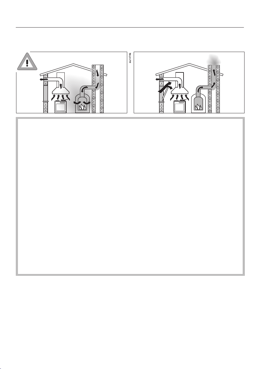
Using at the same time as other heating appliances that depend on the air from the room
Warning - danger of toxic fumes!
Great care should be taken when using the downdraft extractor at
the same time and in the same room or area of the house as
another heating appliance which depends on the air in the room.
Such appliances include gas, oil, wood or coal-fired boilers and
heaters, continuous flow or other water heaters, gas cooktops, or
ovens which draw air in from the room and duct exhaust gases out
through a chimney or extraction ducting.
When used in extraction mode, with or without an external motor
fitted, or in recirculation mode with a recirculation box installed
outside the room, the downdraft extractor draws air in from the
room in which it is installed and from neighbouring rooms.
If there is insufficient air, an underpressure will occur. The heating
appliance will be starved of oxygen, impairing combustion.
Harmful gases could be drawn out of the chimney or extraction
ducting back into the room, with potentially fatal consequences.
10
Page 11

Warning and Safety instructions
In order to ensure safe operation, and to prevent gases given off
by the heating appliances from being drawn back into the room
when the downdraft extractor and the heater are in operation
simultaneously, an underpressure in the room of 0.04 mbar (4 pa)
is the maximum permissible.
Ventilation can be maintained by air inlets which cannot be
blocked, in windows, doors or outside wall vents, or by other
technical measures, such as ensuring that the downdraft extractor
can only be switched on when the heating appliance is switched
off or vice versa. A ventilation brick alone is not generally sufficient
to ensure safe ventilation.
The overall ventilation condition of the dwelling must be taken into
account. If in any doubt, the advice of a competent builder or, for
gas, a qualified gas fitter (registered with an official gas safety
body in accordance with national safety regulations) must be
sought.
If the downdraft extractor is used in recirculation mode, where the
air is directed back into the room in which it is located, operating a
heating appliance which depends on the room air at the same time
is not hazardous.
11
Page 12

Warning and Safety instructions
Correct use
Open flames are a fire hazard!
Never use an open flame beside the downdraft extractor. To avoid
the danger of fire, do not flambé or grill over an open flame. When
switched on, the downdraft extractor could draw flames into the
filter. Kitchen grease deposits could ignite.
Overheated oil and fat can ignite, causing fire damage to the
downdraft extractor.
When cooking with oil or fat, chip pans and deep fat fryers etc., do
not leave the pans unattended. Similarly, never leave an open grill
unattended when grilling.
Do not use the downdraft extractor without the filter in place. This
way you will avoid the risk of grease and dirt getting into the
appliance and hindering its smooth operation.
The downdraft extractor can get very hot during cooking due to
the heat from the cooktop.
Do not touch the housing or the grease filter until the downdraft
extractor has cooled down.
Do not use the downdraft extractor for resting objects on.
Keep liquids away from the downdraft extractor.
Liquids can damage the extractor if they get into it.
Light objects can be drawn into the downdraft extractor and
impair its operation.
Do not place any light objects (e.g. paper towels) within close
proximity of the downdraft extractor.
If you are operating a gas cooking appliance directly next to the
downdraft extractor, the FlameGuard must be placed between the
downdraft extractor and the appliance.
12
Page 13

Warning and Safety instructions
Cleaning and care
The steam from a steam cleaning appliance could reach electrical
components and cause a short circuit.
Do not use a steam cleaner to clean the downdraft extractor.
There is a risk of fire if cleaning is not carried out as described in
these operating instructions.
Accessories
Use only genuine original Miele spare parts. If spare parts or
accessories from other manufacturers are used, the warranty will be
invalidated, and Miele cannot accept liability.
13
Page 14
Caring for the environment
Disposal of the packing material
The transport and protective packaging
has been selected from materials which
are environmentally friendly for
disposal, and can normally be recycled.
Recycling the packaging reduces the
use of raw materials in the
manufacturing process and also
reduces the amount of waste in landfill
sites. Ensure that any plastic
wrappings, bags etc. are disposed of
safely and kept out of the reach of
babies and young children. Danger of
suffocation.
Disposing of your old appliance
Electrical and electronic appliances
often contain valuable materials. They
also contain specific materials,
compounds and components, which
were essential for their correct function
and safety. These could be hazardous
to human health and to the environment
if disposed of with your domestic waste
or if handled incorrectly. Please do not,
therefore, dispose of your old appliance
with your household waste.
Please dispose of it at your local
community waste collection / recycling
centre for electrical and electronic
appliances. You are also responsible for
deleting any personal data that may be
stored on the appliance prior to
disposal. Please ensure that your old
appliance poses no risk to children
while being stored prior to disposal.
14
Page 15
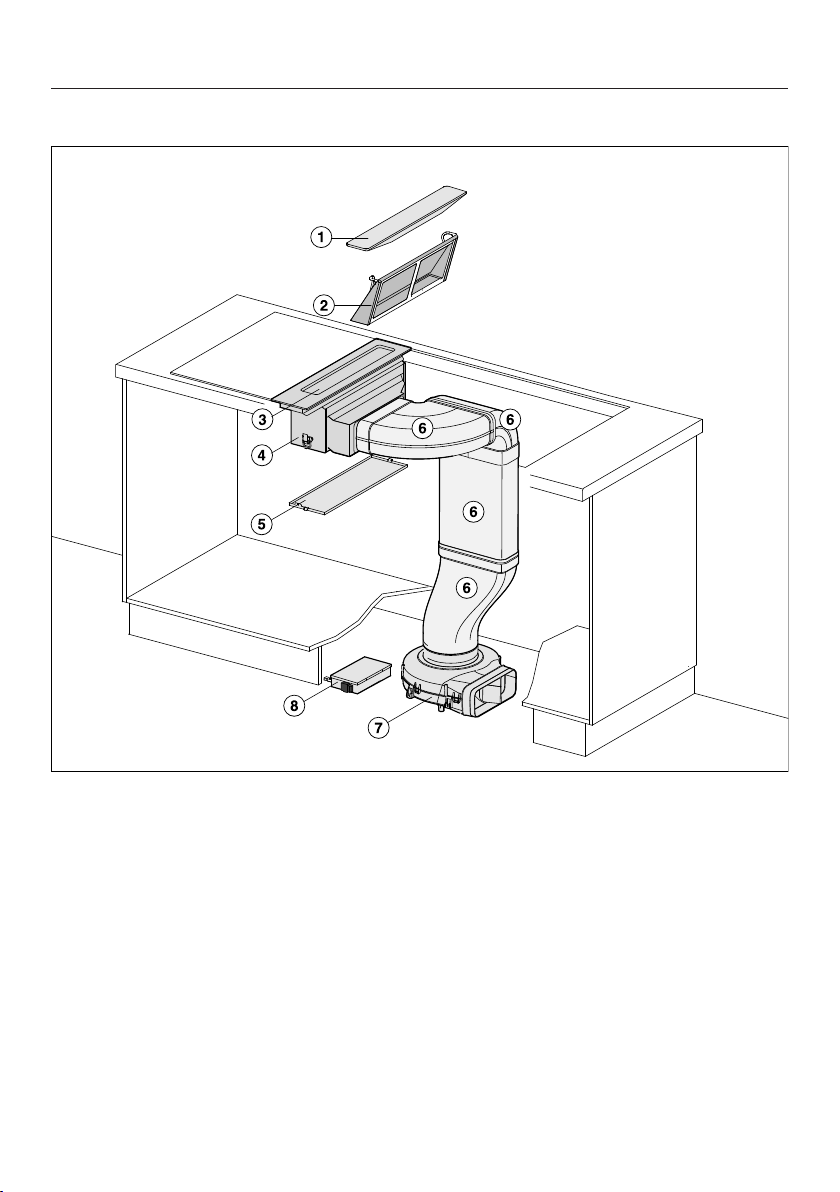
Downdraft extractor
Overview
a
FlameGuard
b
Grease filter
c
Cover with control unit
d
Casing
e
Moisture collection tray
f
Air duct
g
Fan
h
E-box
15
Page 16
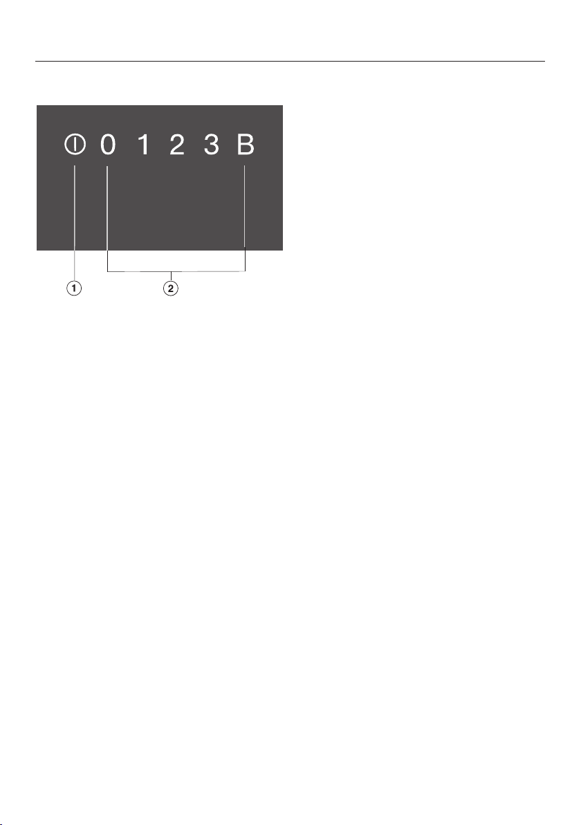
Overview
Controls / Indicators
a
For switching the downdraft extractor on/off
b
Numerical keybank for setting the power level
16
Page 17

Overview
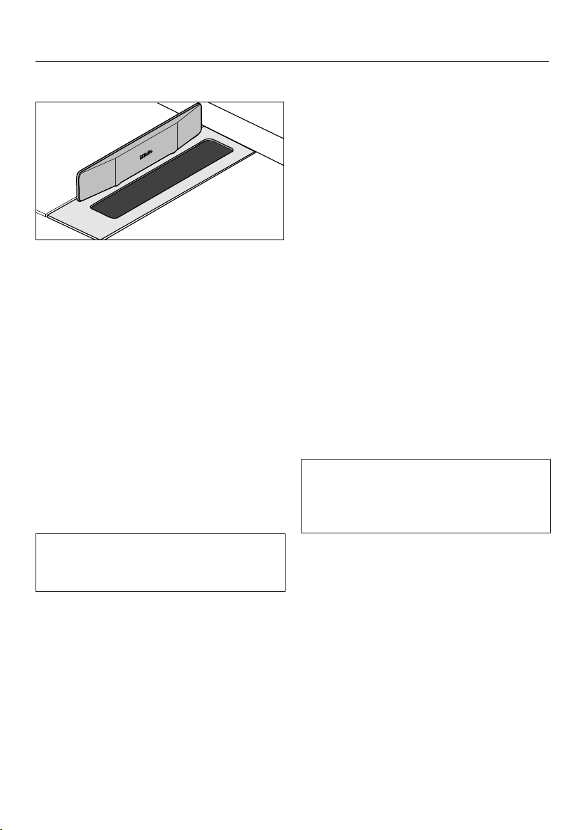
Accessories supplied
The accessories supplied with your
appliance, as well as a range of optional
ones, are available to order from Miele
(see “Optional accessories”).
FlameGuard
For fitting in place between the
downdraft extractor and a gas cooking
appliance.
17
Page 18

Cleaning the SmartLine appliance for the first time
Please stick the extra data plate for
the appliance supplied with this
documentation in the space provided
in the “Service” section of this
booklet. Alternatively, the additional
label can be stuck near the appliance
if the appliance markings are not
visible after installation.
Remove any protective wrapping and
stickers (except the data plate).
Clean the ceramic surface with a
damp cloth, and then wipe dry.
18
Page 19

Depending on the model of the
downdraft extractor, the following
options are available:
Air extraction mode
The air is drawn in and cleaned by the
grease filter and directed outside.
Recirculation mode
(DUU 1000(-1) conversion kit required)
The air is drawn in and cleaned by the
grease filter. The air is then directed into
the recirculation box where it is also
cleaned by the charcoal filter. The
cleaned air is then recirculated back
into the kitchen.
Description of the functions
19
Page 20

Tips on saving energy
This downdraft extractor operates very
efficiently and economically. The
following will help you to save even
more energy when using it:
- It is important to ensure that the
kitchen is well ventilated during
operation. In extraction mode if there
is insufficient air flow, the downdraft
extractor cannot operate efficiently
and this causes increased operating
noise levels.
- Always cook with the lowest possible
cooking setting. This produces fewer
cooking vapours, so you can use a
lower extractor power level and
therefore benefit from reduced energy
consumption.
- Check the selected power level on
the downdraft extractor. A low power
level is usually sufficient. Only use the
Booster setting when necessary.
- When a large volume of cooking
vapours are being produced, switch
to a high power level in good time.
This is more efficient than operating
the downdraft extractor for longer to
try to capture cooking vapours which
have already been distributed
throughout the kitchen.
- Switch the downdraft extractor off
after cooking.
- Clean or replace the filters at regular
intervals. Heavily soiled filters reduce
performance, increase the risk of fire
and are unhygienic.
20
Page 21
Operation
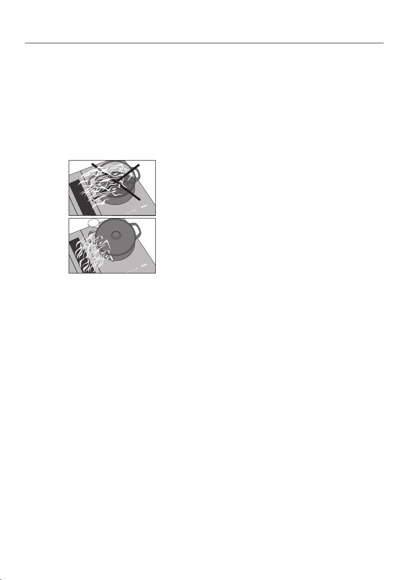
FlameGuard
Fit the magnetic FlameGuard in
position next to the downdraft
extractor when you are operating a
gas cooking appliance directly next to
the extractor.
Switching the downdraft extractor on
The downdraft extractor must only be
operated when the FlameGuard has
been removed from completely
covering the extractor.
Remove the FlameGuard.
Touch the sensor.
The sensor controls will light up.
Setting/Changing the power level
For light to heavy cooking vapours and
odours, select from power levels 1 to 3.
For short periods of cooking food with
intensive vapours and a strong aroma,
e.g. when searing meat, select Booster
settingB.
Touch the required power level.
Booster
The maximum duration for the Booster
is 10minutes.
To switch the Booster off early, set a
different power level.
Switching the downdraft extractor off
Touch the sensor.
The sensor controls go out.
If the downdraft extractor is not
switched off, it will switch itself off
12hours after the last automatic
operation.
If no further entry is made, the
downdraft extractor will switch itself
off after a few seconds.
21
Page 22
Operation
Run-on time
In order to rid kitchen air of steam and
odours, the downdraft extractor
continues to run for 5minutes on the
power level that was set last. The
power level is gradually reduced during
the run-on time. The current power level
pulsates during the run-on time.
Useful tip: To help release vapours
effectively with pans over 15cm high,
place a wooden spoon between the lid
and the pan.
22
Page 23

Cleaning and care
Risk of burning due to hot
surfaces.
The surfaces will be hot after use.
Switch the downdraft extractor and
the cooking elements off.
Allow the surfaces to cool down
before cleaning the downdraft
extractor.
Risk of damage due to moisture
ingress.
The steam from a steam cleaning
appliance could reach electrical
components and cause a short
circuit.
Do not use a steam cleaner to clean
the downdraft extractor.
The use of unsuitable cleaning
agents can cause the surfaces to
discolour or alter. All surfaces are
susceptible to scratching.
Remove any residual cleaning agent
immediately.
Never use abrasive sponges or
cleaning agents.
Allow the SmartLine appliance to
cool down before cleaning.
Clean the SmartLine appliance and
accessories after each use.
Dry the SmartLine appliance
thoroughly every time after cleaning
to avoid limescale residue.
Unsuitable cleaning agents
To avoid damaging the surfaces of the
appliance, do not use:
- washing-up liquid,
- cleaning agents containing soda,
alkalines, ammonia, acids or
chlorides,
- cleaning agents containing descaling
agents,
- stain and rust removers,
- abrasive cleaning agents, e.g.
powder cleaners and cream cleaners,
- solvent-based cleaning agents,
- dishwasher cleaner,
- grill and oven cleaners,
- glass cleaning agents,
- hard, abrasive brushes or sponges
(e.g. pot scourers), or sponges which
have been previously used and still
contain abrasive cleaning agents,
- dirt erasers.
23
Page 24

Cleaning and care
Ceramic surface
Risk of damage by pointed
objects.
The seal between the SmartLine
element and the worktop could
suffer damage.
Do not use pointed objects for
cleaning.
Do not use washing-up liquid to
clean the appliance. Using washingup liquid will not remove all soiling
and residues. An invisible film can
develop that can lead to
discolouration of the ceramic glass.
This discolouration cannot be
removed.
Clean the ceramic surface regularly
with a proprietary ceramic glass
cleaning agent.
Remove any coarse soiling with a
damp cloth and more stubborn
soiling with a glass scraper.
Then clean the ceramic glass surface
with the Miele ceramic and stainless
steel cooktop cleaner (see “Optional
accessories”) or with a proprietary
ceramic glass cleaner applied with
paper towel or a clean cloth. Please
follow the cleaning agent
manufacturer's instructions.
Moisture collection tray
Clean the moisture collection tray if
liquids have boiled over or spilled into
the downdraft extractor.
Remove and clean the grease filter as
described in the “Grease filter”
section.
Hold the moisture collection tray and
open the 2 clips (1x front, 1x rear).
Carefully remove the tray from the
casing, making sure it is kept
horizontal.
Pour out the liquid.
Clean and dry the moisture collection
tray.
Clean and dry the accessible inside
of the downdraft extractor.
Fasten the moisture collection tray
back onto the casing.
Refit the grease filter and the cover.
Clean the ceramic surface with a
damp cloth, and then wipe dry.
Ensure that all cleaner residues are
removed.
Any marks left by limescale and
water residues can be removed using
Miele's ceramic and stainless steel
cooktop cleaner.
24
Page 25

Cleaning and care
Grease filter
The reusable metal grease filter in the
downdraft extractor removes solid
particles from kitchen vapours (grease,
dust, etc.) and therefore prevents
soiling of the downdraft extractor.
Accumulated grease solidifies over a
longer period of time and makes
cleaning more difficult. The grease filter
should therefore be cleaned at least
every 3 to 4 weeks.
Risk of fire due to soiled grease
filter.
Grease collected in the grease filter
can ignite.
Clean the grease filter regularly.
Removing the grease filter
Remove the FlameGuard if
necessary.
Carefully remove the grease filter.
Ensure that you do not tilt the grease
filter.
Use a standard household
dishwasher detergent.
Select a dishwasher programme with
a wash temperature between 50°C
and 65°C.
Depending on the detergent used,
cleaning the grease filter in a
dishwasher can cause permanent
discolouration to the internal surfaces
of the filter. This will not affect the
functioning of the grease filter in any
way.
Fitting the grease filter
Pour out any liquid which has
collected at the bottom of the grease
filter.
Cleaning the grease filter by hand
Clean the grease filter with a soft
nylon brush in a mild solution of hot
water and a little washing-up liquid.
Do not use concentrated washing-up
liquid.
Cleaning the grease filter in the dishwasher
Place the grease filter with its base
facing upwards in the lower basket.
Ensure the spray arm is not
obstructed.
Fit the grease filter so that the straight
side of the grease filter is on the side
that connects to the air duct.
Interior of the casing
When removing the grease filter for
cleaning, also clean off any
accessible oil or fat build-up from the
casing. Doing so will prevent a fire
hazard.
25
Page 26

Problem solving guide
With the help of the following guide, minor faults in the performance of the
appliance, some of which may result from incorrect operation, can be remedied
without contacting Miele. This will save you time and money because you won't
need a service call.
Please note that a call-out charge will be applied to unnecessary service visits
where the problem could have been rectified as described in these operating
instructions.
Problem Possible cause and remedy
The SmartLine
appliance cannot be
switched on.
The power levels 1 to B
light up one after the
other.
There is no power to the SmartLine appliance.
Check if the circuit breaker has tripped. Contact
an electrician or Miele (for the minimum fuse
rating, see data plate).
There may be a technical fault.
Disconnect the SmartLine appliance from the
mains electricity supply for approx. 1 minute by
– switching off at the wall socket and withdrawing
the plug, or
– switching off the main circuit breaker or residual
current device.
If, after resetting the fuse in the mains fuse box or
the residual current protection device, the
SmartLine appliance will still not switch on,
contact a qualified electrician or Miele.
An automatic reset is performed after an
interruption to the power supply.
26
Page 27

Optional accessories
Miele offers a range of useful
accessories, as well as cleaning and
conditioning products for your
appliance.
These products can be ordered from
the Miele online shop.
They can also be ordered directly from
Miele (see end of this booklet for
contact details).
FlameGuard
For fitting in place between the
downdraft extractor and a gas cooking
appliance.
Original Miele ceramic and
stainless steel cleaner 250ml
Removes heavy soiling, limescale
deposits and aluminium residues.
Original Miele all purpose microfibre cloth
Removes finger marks and light soiling.
27
Page 28

Service
Contact in case of fault
In the event of any faults which you cannot remedy yourself, please contact Miele.
You can book a Miele customer service call-out online at www.miele.com/
service.
Contact information for Miele can be found at the end of this booklet.
Please quote the model and serial number of your appliance when contacting
Miele. This information can be found on the data plate.
Data plate
Adhere the extra data plate supplied with the appliance in the space below. Make
sure that the model number matches the one specified on the back cover of these
operating and installation instructions.
Warranty
The manufacturer's warranty for this appliance is 2years.
For further information, please refer to your warranty booklet.
28
Page 29

*INSTALLATION*
Installation
Safety instructions for installation
Risk of damage from incorrect installation.
Incorrect installation can cause damage to the SmartLine appliance.
The SmartLine appliance must only be installed by a suitably qualified and
competent person.
Damage from falling objects.
Take care not to damage the SmartLine appliance when fitting wall units above
it.
Fit the wall units before the SmartLine appliance.
After installation, the mains connection cable of the SmartLine
appliance must not come into contact with any moving kitchen
component (e.g. a drawer) or be subject to mechanical loads which
could damage it.
Combination with gas appliances
Only Miele CS 7xxx gas appliances may be installed next to the
downdraft extractor.
Carefully observe the safety clearances listed on the following
pages.
All pipework, ducting and fittings must be of non-flammable
material and comply with all relevant national and local building
regulations.
The appliance must not be connected to a chimney or vent flue
which is in current use for exhausting fumes from appliances burning
gas or other fuels. Neither should it be connected to ducting which
ventilates rooms with fireplaces.
If exhaust air is to be extracted into a chimney or ventilation duct
no longer used for other purposes, seek professional advice.
29
Page 30

*INSTALLATION*
Installation
Installation examples
Recirculation mode
Air extraction mode
30
Page 31

*INSTALLATION*
Installation
Surface-mounted
Installation notes – surface-mounted
Sealing between the SmartLine appliance and the worktop
The SmartLine appliance and
worktop may be damaged if the
appliance needs to be removed after
it has been sealed with a sealant.
Do not use any sealant between the
SmartLine appliance and the
worktop.
The sealing strip under the edge of
the top part of the appliance
provides a sufficient seal for the
worktop.
Tiled worktop
Grout lines and the hatched area
underneath the SmartLine appliance
frame must be smooth and even. If they
are not, the SmartLine appliance will
not sit flush with the worktop and the
sealing strip underneath the top part of
the appliance will not provide a good
seal between the appliance and the
worktop.
Sealing strip
Dismantling the SmartLine appliance
for service purposes may damage
the sealing strip underneath the edge
of the SmartLine appliance.
Always replace the sealing strip
before reinstalling the cooktop.
31
Page 32

*INSTALLATION*
Installation
Installing several SmartLine appliances
The gaps between the individual
SmartLine appliances must be sealed
with a silicone sealant that is heatresistant to at least 160°C. With flushfit installation, the gap between the
SmartLine appliance(s) and the worktop
must also be sealed with a silicone
sealant that is heat-resistant to at least
160°C.
After installation, the SmartLine
appliances must be easily accessible
from below, so that the bottom half of
the casing can be removed for
maintenance. If the SmartLine
appliances are not accessible from
below, the sealant must be removed so
that they can be removed.
Worktop depth
The downdraft extractor can be
installed with the connector for the air
duct on either the right or the left-hand
side.
Minimum worktop depth for
- right connector 600mm
- left connector 665mm
32
Page 33

*INSTALLATION*
B
500
+1
ß
R 4
B
10
0
10
Worktop cut-out – surface-mounted
Installation
Information for calculating the cut-out
The appliances overlap the worktop by 10mm.
When installing several appliances, a distance of 2mm must be observed between
the individual appliances.
Calculating cut-out dimensionB
1 appliance = width of the appliance minus 10mm on the right, minus 10mm on
the left
Several appliances = total width of the appliances plus 2mm distance between
the appliances, minus 10mm on the right, minus 10mm on the left.
Some examples are illustrated below.
33
Page 34

*INSTALLATION*
Installation
Installation with a downdraft extractor
Sample combinations Numberxwidth [mm] Dimension
Cooking
appliances
Downdraft
extractor
1 x 378 1 x 120
B
[mm]
480
+1
2 x 378 1 x 120
1x378
2 x 120
1x620
3 x 378 2 x 120
2x378
2 x 120
1x620
4 x 378 2 x 120
1 x 620 2 x 120
860
1224
1362
1604
1742
844
+1
+1
+1
+1
+1
+1
34
Page 35

*INSTALLATION*
Installation without a downdraft extractor
Sample combinations Numberxwidth [mm] DimensionB
Cooking appliances
1 x 378
Installation
[mm]
+1
358
2 x 378
1x378
1x620
3 x 378
2x378
1x620
4 x 378
738
980
1118
1360
1498
+1
+1
+1
+1
+1
35
Page 36

*INSTALLATION*
Installation
Spacer bars – surface-mounted
When installing several SmartLine appliances, an additional spacer bar must be
fitted in between the individual appliances.
The clips supplied with the spacer bars are only required for installing a
CSDA700xFL.
Installing 3 appliances and 2 spacer bars
Spacer bars for the downdraft extractor – surface-mounted
a
Brackets
36
Page 37

*INSTALLATION*
Installation dimensions– Surface-mounted
All dimensions in this instruction booklet are given in mm.
Installation
a
Front
b
Fan (in the plinth on the floor)
c
Air duct
d
E-box
37
Page 38

*INSTALLATION*
Installation
Air duct dimensions – surface-mounted – worktop depth
600mm
Side view
a
For maintenance work, it must be possible to remove the rear cabinet wall.
The cabinet wall and an adjoining room wall or a piece of furniture must be at
least 110mm apart to ensure sufficient room for the exhaust ducting.
b
After installation, the removable moisture collection tray must be accessible
from below.
Two quick-release catches have to be opened to remove the tray.
c
Duct length must be adapted to the height of the base unit.
Standard delivery 500mm
d
Plinth fan
38
Page 39

*INSTALLATION*
Installation
Front view
View from above
39
Page 40

*INSTALLATION*
Installation
Air duct dimensions – surface-mounted – worktop depth greater
than 600mm
View from the side – right air duct connection
a
For maintenance work, it must be possible to remove the rear cabinet wall.
The cabinet wall and an adjoining room wall or a piece of furniture must be at
least 110mm apart to ensure sufficient room for the exhaust ducting.
b
Variable length of middle section
c
After installation, the removable moisture collection tray must be accessible
from below.
Two quick-release catches have to be opened to remove the tray.
d
Duct length must be adapted to the height of the base unit.
Standard delivery 500mm
e
Plinth fan
x Dimension of which the worktop is deeper than 600mm.
40
Page 41

*INSTALLATION*
View from the front – right air duct connection
Installation
View from above – right air duct connection
41
Page 42

*INSTALLATION*
Installation
If you want to install the air duct to the left of the downdraft extractor, the
worktop must be at least 665mm deep.
View from the front – left air duct connection
View from above – left air duct connection
42
Page 43

*INSTALLATION*
Installation
Installation – surface-mounted
If the worktop is more than 24mm
deep, it must be cut out underneath
on the building-in side on the right or
left-hand side.
a
Worktop
b
Maximum 24mm
c
12 mm
Securing the bracket
1 bracket (supplied with the spacer bar)
must be secured centrally to the right or
left-hand side of the cut-out.
Wooden worktops
Fit the bracket so that it sits flush
with the top edge of the worktop cutout.
Secure the bracket with the
3.5x25mm wood screws supplied.
Granite and marble worktops
You will need heavy-duty doublesided tape (not supplied) to secure the
bracket.
Stick the tape along the top edge of
the worktop cut-out.
Fit the bracket so that it sits flush
with the top edge of the worktop cutout.
Press the bracket firmly into position.
43
Page 44

*INSTALLATION*
Installation
Preparing the worktop
Create the worktop cut-out.
Remember to maintain the minimum
safety distances (see "Installation –
Safety distances").
Seal the cut surfaces of wooden
worktops with a suitable sealant to
avoid swelling caused by moisture.
The sealant must be heat-resistant.
Make sure the sealant does not
come into contact with the top
surface of the worktop.
Fitting the spacer bars
Use the middle screw holes if one of the
following SmartLine appliances is
installed to the right or left of the spacer
bar: CS7611, CS 7641, CS7101(-1),
CS7102(-1)
Wooden worktops
Position the spacer bars flush onto
the upper edge of the cut-out.
Secure the spacer bars with the
3.5x25mm wood screws supplied.
Granite and marble worktops
You will need heavy-duty doublesided tape (not supplied) to secure the
spacer bars.
44
Stick the tape along the top edge of
the worktop cut-out.
Position the spacer bars flush onto
the upper edge of the cut-out.
Press the spacer bars firmly into
place.
Page 45

*INSTALLATION*
Installing the downdraft extractor
The downdraft extractor can be
installed with the connector for the air
duct on either the right or the left-hand
side.
Installation
Remove the moisture collection tray
from the casing.
a
Connector for air duct on the right
b
Connector for air duct on the left
Stick the supplied sealing strip under
the edge of the cover. Do not apply
the sealing strip under tension.
Fit the clips onto the spacer bars.
Guide the control cable downwards
between the spacer bars.
Fit the cover onto the spacer bars.
Fasten the casing from the inside with
the screws on the right and left
sides (3 in each case).
Fasten the moisture collection tray.
Mount the air duct.
Ensure that the air duct is not under
mechanical tension after installation!
45
Page 46

*INSTALLATION*
Installation
E-box
a
Mains connection cable
b
Connection to window contact
c
Connection socket for the fan power
cable
d
Connection socket for the fan
control cable
e
Connection socket for the control
unit cable
Connection to window contact, if required
The window contact is
connected to the mains voltage.
Danger of electric shock!
Disconnect the downdraft extractor
from the mains electricity supply
before connecting the switching
system.
The connection cable of the
switching system must only be
connected by a suitably qualified and
competent electrician.
The connection cable of the
switching system must be of the
correct type and cross-sectional area
in strict accordance with current
national and local safety regulations
and must not exceed 2.0m in length.
The switching system must be
equipped with a potential-free
contact suitable for 230V, 1A. The
extractor is switched off when the
switch is open.
Only use suitable switching systems
(e.g. window contact switches,
pressure switches).
The switching system must be
suitable for use with inductive loads
(BLDC motor).
Use switching systems in strict
accordance with current national and
local safety regulations.
46
Page 47

*INSTALLATION*
Installation
Loosen the lug and pull the plug out.
Loosen the strain relief screw and
unlock the casing on both sides.
Open the casing.
Remove the stopper.
Exchange the jumper with the
connection cable of the switching
system.
Close the casing.
Connecting the e-box
Connect the fan power cable and fan
control cable to the e-box and the
fan.
Connect the control unit cable to the
e-box.
The socket positions are designed in
such a way that they cannot be mixed
up.
Connect the downdraft extractor to
the mains electricity supply.
Check that the downdraft extractor
works.
Sealing the gaps
Seal the gaps between the individual
SmartLine appliances, and between
the flush-fit SmartLine appliances
and the worktop, with a silicone
sealant that is heat-resistant to at
least 160°C.
Unsuitable sealant can damage
natural stone.
For natural stone worktops and
natural stone tiles, only use silicone
sealant that is specially formulated
for natural stone.
Please follow the manufacturer's
instructions.
Tighten the strain relief screw.
Reinsert the plug.
47
Page 48

*INSTALLATION*
Installation
Flush-fit
Installation notes – flush-fit
Flush-fit installation is only possible in
natural stone (granite, marble), solid
wood and tiled worktops. For
installation in worktops made of other
materials, please consult the relevant
manufacturer as to whether their
worktops are suitable for flush-fit
installation.
The internal width of the base unit
underneath the appliance must be at
least as wide as the inner worktop cutout (see “Installation – Installation
dimensions – Flush”), so that the
SmartLine appliance is easily
accessible from underneath after
installation and the bottom half of the
casing can be removed for
maintenance. If the appliance is not
freely accessible from below after
installation, the sealant must be
removed so that the appliance can be
removed.
Natural stone worktops
The SmartLine appliance is set directly
in the cut-out.
Solid wood worktops, tiled worktops,
glass worktops
The SmartLine appliance is set on a
wooden frame inside the cut-out. The
frame must be provided on site and is
not supplied with the appliance.
Sealing strip
Dismantling the SmartLine appliance
for service purposes may damage
the sealing strip underneath the edge
of the SmartLine appliance.
Always replace the sealing strip
before reinstalling the cooktop.
48
Page 49

*INSTALLATION*
Installation
Installing several SmartLine appliances
The gaps between the individual
SmartLine appliances must be sealed
with a silicone sealant that is heatresistant to at least 160°C. With flushfit installation, the gap between the
SmartLine appliance(s) and the worktop
must also be sealed with a silicone
sealant that is heat-resistant to at least
160°C.
After installation, the SmartLine
appliances must be easily accessible
from below, so that the bottom half of
the casing can be removed for
maintenance. If the SmartLine
appliances are not accessible from
below, the sealant must be removed so
that they can be removed.
Worktop depth
The downdraft extractor can be
installed with the connector for the air
duct on either the right or the left-hand
side.
Minimum worktop depth for
- right connector 600mm
- left connector 665mm
49
Page 50

*INSTALLATION*
B
A
524
500
+
1
+1
ß R 4
B
A
0 2
12
0
10
5,5
+
0,5 *
0 2
B
A
12
0
10
5,5
+
0,5 *
Installation
Worktop cut-out – flush-fit
Natural stone worktop Wooden worktop
0.5
+
* 7
mm with CS7611FL
Information for calculating the cut-out
The appliances overlap the stepped cut-out by 10mm.
When installing several appliances, a distance of 2mm must be observed between
the individual appliances.
Calculating cut-out dimensionA
1 appliance = width of the appliance plus 2mm on the right, plus 2mm on the left.
Several appliances = total width of the appliances plus 2mm distance between
the appliances, plus 2mm on the right, plus 2mm on the left
Calculating cut-out dimensionB = cut-out dimension A minus 12mm on the right,
minus 12mm on the left.
Some examples are illustrated below.
50
Page 51

*INSTALLATION*
Installation with a downdraft extractor
Sample combinations
Numberxwidth [mm]
Cooking
appliances
Downdraft
extractor
DimensionA
[mm]
Installation
DimensionB
[mm]
1 x 378 1 x 120
2 x 378 1 x 120
1x378
2 x 120
1x620
3 x 378 2 x 120
2x378
2 x 120
1x620
4 x 378 2 x 120
1 x 620 2 x 120
504
884
1248
1386
1628
1766
868
+1
+1
+1
+1
+1
+1
+1
480
860
1224
1362
1604
1742
844
+1
+1
+1
+1
+1
+1
+1
51
Page 52

*INSTALLATION*
Installation
Installation without a downdraft extractor
Sample
combinations
Numberxwidth
[mm]
Cooking
appliances
1 x 378
2 x 378
1x378
1x620
3 x 378
2x378
1x620
4 x 378
DimensionA
[mm]
+1
382
+1
762
+1
1004
+1
1142
+1
1384
+1
1522
DimensionB
[mm]
+1
358
+1
738
+1
980
+1
1118
+1
1360
+1
1498
52
Page 53

*INSTALLATION*
Installation
Spacer bars – flush-fit
When installing several SmartLine appliances, an additional spacer bar must be
fitted in between the individual appliances.
The clips supplied with the spacer bars are only required for installing a
CSDA700xFL.
Installing 3 appliances and 2 spacer bars
Spacer bars for the downdraft extractor – flush-fit
a
Brackets
53
Page 54

*INSTALLATION*
Installation
Installation dimensions–Flush
All dimensions in this instruction booklet are given in mm.
a
Front
b
Fan (in the plinth on the floor)
c
Stepped cut-out (for detailed
illustrations, see “Installation –
Worktop cut-out – flush-fit”)
54
d
12mm wooden frame (not supplied,
for detailed illustrations, see
“Installation – Worktop cut-out –
flush-fit”)
e
Air duct
f
E-box
Page 55

*INSTALLATION*
Air duct dimensions – flush-fit – worktop depth 600mm
Side view
Installation
a
For maintenance work, it must be possible to remove the rear cabinet wall.
The cabinet wall and an adjoining room wall or a piece of furniture must be at
least 110mm apart to ensure sufficient room for the exhaust ducting.
b
After installation, the removable moisture collection tray must be accessible
from below.
Two quick-release catches have to be opened to remove the tray.
c
Duct length must be adapted to the height of the base unit.
Standard delivery 500mm
d
Plinth fan
55
Page 56

*INSTALLATION*
Installation
Front view
View from above
56
Page 57

*INSTALLATION*
Air duct dimensions – flush-fit – worktop depth greater than
600mm
View from the side – right air duct connection
Installation
a
For maintenance work, it must be possible to remove the rear cabinet wall.
The cabinet wall and an adjoining room wall or a piece of furniture must be at
least 110mm apart to ensure sufficient room for the exhaust ducting.
b
Variable length of middle section
c
After installation, the removable moisture collection tray must be accessible
from below.
Two quick-release catches have to be opened to remove the tray.
d
Duct length must be adapted to the height of the base unit.
Standard delivery 500mm
e
Plinth fan
x Dimension of which the worktop is deeper than 600mm.
57
Page 58

*INSTALLATION*
Installation
View from the front – right air duct connection
View from above – right air duct connection
58
Page 59

*INSTALLATION*
If you want to install the air duct to the left of the downdraft extractor, the
worktop must be at least 665mm deep.
View from the front – left air duct connection
Installation
View from above – left air duct connection
59
Page 60

*INSTALLATION*
Installation
Installation – flush-fit
If the worktop is more than 28mm
deep, it must be cut out underneath
on the building-in side on the right or
left-hand side.
a
Worktop
b
Maximum 24mm
c
12 mm
Securing the bracket
1 bracket (supplied with the spacer bar)
must be secured centrally to the right or
left-hand side of the cut-out.
Wooden worktops
Fit the bracket so that it sits flush
with the top edge of the lower step of
the stepped cut-out.
Secure the bracket with the
3.5x25mm wood screws supplied.
Granite and marble worktops
You will need heavy-duty doublesided tape (not supplied) to secure the
bracket.
60
Stick the tape onto the upper edge of
the lower step of the stepped cut-out.
Fit the bracket so that it sits flush
with the top edge of the lower step of
the stepped cut-out.
Press the bracket firmly into position.
Page 61

*INSTALLATION*
Installation
Preparing the worktop
Create the worktop cut-out.
Remember to maintain the minimum
safety distances (see "Installation –
Safety distances").
Seal the cut surfaces of wooden
worktops with a suitable sealant to
avoid swelling caused by moisture.
The sealant must be heat-resistant.
Make sure the sealant does not
come into contact with the top
surface of the worktop.
For wooden worktops, secure the
wooden frames 5.5mm below the
upper edge of the worktop.
For CS7611FL, the wooden frame
must be secured 7mm under the
upper edge of the worktop.
Fitting the spacer bars
Use the middle screw holes if one of the
following SmartLine appliances is
installed to the right or left of the spacer
bar: CS7611, CS 7641, CS7101(-1),
CS7102(-1)
Wooden worktops
Position the spacer bars flush onto
the lower step of the stepped cut-out.
Secure the spacer bars with the
3.5x25mm wood screws supplied.
Granite and marble worktops
You will need heavy-duty doublesided tape (not supplied) to secure the
spacer bars.
Stick the tape onto the lower step of
the stepped cut-out.
Position the spacer bars flush onto
the lower step of the stepped cut-out.
Press the spacer bars firmly into
place.
61
Page 62

*INSTALLATION*
Installation
Installing the downdraft extractor
The downdraft extractor can be
installed with the connector for the air
duct on either the right or the left-hand
side.
Remove the moisture collection tray
from the casing.
a
Connector for air duct on the right
b
Connector for air duct on the left
Stick the supplied sealing strip under
the edge of the cover. Do not apply
the sealing strip under tension.
Fit the clips onto the spacer bars.
Guide the control cable downwards
between the spacer bars.
Fit the cover onto the spacer bars.
62
Fasten the casing from the inside with
the screws on the right and left
sides (3 in each case).
Fasten the moisture collection tray.
Mount the air duct.
Ensure that the air duct is not under
mechanical tension after installation!
Page 63

*INSTALLATION*
Installation
E-box
a
Mains connection cable
b
Connection to window contact
c
Connection socket for the fan power
cable
d
Connection socket for the fan
control cable
e
Connection socket for the control
unit cable
Connection to window contact, if required
The window contact is
connected to the mains voltage.
Danger of electric shock!
Disconnect the downdraft extractor
from the mains electricity supply
before connecting the switching
system.
The connection cable of the
switching system must only be
connected by a suitably qualified and
competent electrician.
The connection cable of the
switching system must be of the
correct type and cross-sectional area
in strict accordance with current
national and local safety regulations
and must not exceed 2.0m in length.
The switching system must be
equipped with a potential-free
contact suitable for 230V, 1A. The
extractor is switched off when the
switch is open.
Only use suitable switching systems
(e.g. window contact switches,
pressure switches).
The switching system must be
suitable for use with inductive loads
(BLDC motor).
Use switching systems in strict
accordance with current national and
local safety regulations.
63
Page 64

*INSTALLATION*
Installation
Loosen the lug and pull the plug out.
Loosen the strain relief screw and
unlock the casing on both sides.
Open the casing.
Remove the stopper.
Exchange the jumper with the
connection cable of the switching
system.
Close the casing.
Connecting the e-box
Connect the fan power cable and fan
control cable to the e-box and the
fan.
Connect the control unit cable to the
e-box.
The socket positions are designed in
such a way that they cannot be mixed
up.
Connect the downdraft extractor to
the mains electricity supply.
Check that the downdraft extractor
works.
Sealing the gaps
Seal the gaps between the individual
SmartLine appliances, and between
the flush-fit SmartLine appliances
and the worktop, with a silicone
sealant that is heat-resistant to at
least 160°C.
Unsuitable sealant can damage
natural stone.
For natural stone worktops and
natural stone tiles, only use silicone
sealant that is specially formulated
for natural stone.
Please follow the manufacturer's
instructions.
Tighten the strain relief screw.
Reinsert the plug.
64
Page 65

*INSTALLATION*
Installation
Exhaust ducting
Before installation, it is important
to read the following information.
This is particularly crucial when using
the downdraft extractor at the same
time as a heating appliance that
relies on oxygen from the same
room, which could result in the buildup of toxic fumes.
It is particularly important that the
“Warning and Safety instructions”
are observed.
The downdraft extractor should be
installed according to local and
national building regulations. Seek
approval from the building inspector
where necessary.
The downdraft extractor has an exhaust
connection of 222x89mm.
In order to achieve optimum
extraction or recirculation
performance and low noise levels,
Miele recommends the installation of
a modular rectangular ducting system
made from approved non-flammable
materials.
- For the rectangular ducting, Miele
recommends not to exceed a
maximum total ducting length of 5 m,
with a maximum number of three
bends.
- Only use wide radius bends.
- The exhaust ducting must not be
kinked or compressed.
- Ensure that all connections are
strong and airtight.
Remember that any constriction of
the airflow will reduce extraction
performance and increase operating
noise.
To achieve the most efficient air
extraction with the lowest noise
levels, please note the following:
- The cross-section of the exhaust
ducting must not be smaller than the
cross-section of the exhaust
connection (see the appliance
dimensions).
- The exhaust ducting should be as
short and straight as possible.
65
Page 66

*INSTALLATION*
Installation
If the exhaust air is to be ducted into
a flue, the ducting must be directed in
the flow direction of the flue.
If ducting is to be laid horizontally, it
must be laid with a downwards
sloping gradient. This is to ensure
that condensate cannot drain back
into the extractor.
If the vent ducting is to run through
rooms, ceiling space, etc. there may
be great variations in temperature
between the different areas. The
problem of condensation will need to
be addressed. The exhaust ducting
will need to be suitably insulated.
Ensure that the ducting can easily be
disconnected from the exhaust
connection in the event the appliance
needs to be taken out of the worktop
for service purposes.
Stick the supplied sealing strip on the
exhaust connection if the ducting
does not sit securely up against the
exhaust connection.
66
Page 67

*INSTALLATION*
Installation
Electrical connection
We recommend that you connect the
SmartLine appliance to the mains via a
suitable switched electrical socket. This
simplifies servicing. The socket must be
easily accessible after the SmartLine
appliance has been installed.
Danger of injury!
Installation, repairs and other work
by unqualified persons could be
dangerous. Miele cannot be held
liable for unauthorised work.
Miele cannot be held liable for
damage or injury (e.g. electric shock)
caused by the lack of or inadequacy
of an on-site earthing system.
If the plug is removed from the
connection cable or if the cable is
supplied without a plug, the
SmartLine appliance must be
connected to the electricity supply
by a suitably qualified electrician.
If the socket is no longer accessible,
or if a hard-wired connection is
planned, an additional means of
disconnection must be provided for
all poles in accordance with the
wiring rules. Suitable means of
disconnection include switches with
an all-pole contact gap of at least
3mm. These include miniature circuit
breakers, fuses and relays. The
connection data can be found on the
data plate. Please ensure this
information matches the household
mains electricity supply.
After installation, ensure that all
electrical components are shielded
and cannot be accessed by users.
Total power output
See data plate.
Connection data
The connection data is given on the
data plate. Please ensure this
information matches the household
mains supply.
Residual current device
For extra safety, it is advisable to
protect the SmartLine appliance with a
suitable residual current device (RCD)
with a trip range of 30mA.
67
Page 68

*INSTALLATION*
Installation
Replacing the mains connection cable
Danger of electric shock!
Incorrect connection to the electricity
supply may result in an electric
shock.
The mains connection cable must
only be replaced in accordance with
current local and national safety
regulations.
When replacing the mains connection
cable, it must be replaced with cable
type H05VV-F by a Miele authorised
service technician or a suitably qualified
and competent electrician in order to
avoid a hazard. These cables are
available from Miele.
68
Page 69

Page 70

Page 71

Miele Experience Centre and
Head Office Melbourne:
1 Gilbert Park Drive
Knoxfield, VIC 3180
Miele Experience Centre South Melbourne:
206-210 Coventry Street
South Melbourne, VIC 3205
Miele Experience Centre and Office Sydney:
3 Skyline Place
Frenchs Forest, NSW 2086
Miele Experience Centre and Office Brisbane:
Tenancy 4C, 63 Skyring Terrace
Newstead, QLD 4006
Miele Experience Centre and Office Perth:
83-85 Sir Donald Bradman Drive
Hilton, SA 5033
Miele Experience Centre and Office Adelaide:
Miele Australia Pty. Ltd. Miele New Zealand Limited
Level 2, 10 College Hill
Freemans Bay, Auckland 1011
Miele Experience Centre
Auckland:
8 College Hill
Freemans Bay, Auckland 1011
Miele Global Headquarters
Germany
Miele & Cie. KG
Carl-Miele-Straße 29
33332 Gütersloh
Federal Republic of Germany
Head Office:
IRD 98 463 631
ACN 005 635 398
ABN 96 005 635 398
Miele Experience Centre Gold Coast:
131 Ferry Road
Southport, QLD 4215
Miele Experience Centre
Wellington:
183 Featherston Street
Wellington 6011
0800 464 353 (0800 4 MIELE)
www.miele.co.nz
205-207 Stirling Highway
Claremont, WA 6010
1300 464 353 (1300 4 MIELE)
www.miele.com.au
Page 72

CSDA7000 FL
M.-Nr. 11 037 890 / 03en-AU, NZ
 Loading...