

Page 1

Microtek
Scanner ICC Profiler
User's Manual
(Windows)
Page 2

Copyright 1998 by Microtek International, Inc.
All rights reserved.
Trademarks
Microtek and ScanMaker are trademarks of Microtek International, Inc. IBM PC is a registered trademark of
International Business Machines Corporation. Microsoft and Windows are registered trademarks of Microsoft
Corporation. Adobe and Adobe Photoshop are trademarks of Adobe Systems Incorporated. Kodak is a
registered trademark of Eastman-Kodak Company. Other product or company names are trademarks or
registered trademarks of their respective holders.
Important
Documents that you scan may be protected under copyright law. The unauthorized use of such documents
could be a violation of the rights of the copyright holder. Microtek bears no responsibility for the
unauthorized use of copyrighted materials.
To obtain optimal results from the Microtek scanning software and user's manual, you should be familiar with
such Windows concepts as pointing, clicking, dragging, and selecting from menus and dialog boxed. If these
things are new to you, refer to your Microsoft Windows User's Guide.
Doc. No. I49-002327
November 1998
Microtek Lab, Inc.
3715 Doolittle Drive
Redondo Beach, CA 90278-1226
Main: 310-297-5000
Sales: 800-654-4160
FAX: 310-297-5050
BBS: 310-297-5102
Technical Support: 310-297-5151
AutoTech fax back system: 310-297-5101
http://www.microtekusa.com
Microtek International, Inc.
6, Industry East Road 3
Science Based Industrial Park
Hsinchu, 30077, Taiwan, R.O.C.
TEL: 886-3-5772155
FAX: 886-3-5772598
ii
Microtek Europe B.V.
Max Euwelaan 68
NL-3062 MA Rotterdam
The Netherlands
TEL: 31-10-2425688
FAX: 31-10-2425699
Page 3

Contents
1 Introduction 1-1
Why you need the Scanner ICC Profiler..................................................................... 1-1
Calibration target ...................................................................................................... 1-2
Taking care of the target ............................................................................................ 1-2
Replacing the target................................................................................................... 1-3
2 Using Microtek Scanner ICC Profiler 2-1
Installing Microtek Scanner ICC Profiler .................................................................... 2-1
Placing calibration target ........................................................................................... 2-2
Placing Q-60R1 reflective target .......................................................................... 2-2
Placing Q-60R1 reflective target on an A4-sized (or Letter) scanner............... 2-2
Placing Q-60R1 reflective target on an A3-sized scanner ............................... 2-2
Placing 4" x 5" Q-60E1 transparency target ......................................................... 2-3
Placing 4" x 5" Q-60E1 transparency target on an A4 twin-plate scanner....... 2-3
Placing 4" x 5" Q-60E1 transparency target on an A3 twin-plate scanner....... 2-3
Placing 4" x 5" Q-60E1 transparency target for TMA .................................... 2-4
Placing 4" x 5" Q-60E1 transparency target on transparency scanner ............ 2-4
Placing 35mm Q-60E3 transparency target for slide scanner................................ 2-5
Calibration Procedure ............................................................................................... 2-6
Step 1: Scan target image .................................................................................... 2-7
Step 2: Align target registration marks................................................................. 2-8
Step 3: Create profile .......................................................................................... 2-9
3 Reference 3-1
The Main Window .................................................................................................... 3-1
Controls............................................................................................................. 3-1
System Menu ..................................................................................................... 3-3
Calibration Window (Preview & Scan target image) ................................................... 3-4
Calibration Window (Align target and create profile).................................................. 3-5
4 Troubleshooting 4-1
iii
Page 4

1
Introduction
Microtek’s Scanner ICC Profiler is a scanner calibration and profiling utility
program designed for use with the professional scanner TWAIN driver —
ScanWizard Pro. Scanner ICC Profiler lets you calibrate the color attributes of
your scanner and create a customized ICC color profile dedicated for the
scanner.
This manual describes how to install and use Scanner ICC Profiler with a
Microtek scanner on PC platform. The scanners covered in this manual are color
flatbeds, color flatbeds with transparency media adapter (TMA), twin-plate
color flatbeds, transparency scanners, and 35mm slide scanners.
Why you need the Scanner ICC Profiler
To each scanner, a generic factory-set ICC color profile is included for use with
ScanWizard Pro. This factory-set profile delivers high color quality in general.
However, scanners, like any high-end device, perform subtle difference in color,
even although they have the same model.
In addition, even if an individual scanner, it also performs differently against
time due to the aging of the lamp, or due to ambient temperature. Scanner ICC
Profiler lets you calibrate your respective scanner, compensate color deviation,
and create a custom scanner color profile that precisely describes the color
characteristics of your scanner. Customized color profile delivers superb color
quality. In order to keep color consistency from time to time, it is recommended
that you carry out calibration each day when you start to use the scanner.
Introduction 1-1
Page 5

Calibration target
Your Scanner ICC Profiler kit includes an industry-standard IT8 color target for
calibration. Depending on the scanner model your purchase, three types of
targets are available:
• Kodak Q-60R1: 5" x 7" reflective target for all flatbed scanners (e.g.,
ScanMaker 4, ScanMaker 5, and ScanMaker 2000).
• Kodak Q-60E1: 4" x 5" transparency target for twin-plate scanner with builtin transparency adapter (e.g., ScanMaker 4, ScanMaker 5, and ScanMaker
2000), as well as for transparency scanner (e.g., ScanMaker 45t Pro).
• Kodak Q-60E3: 35mm transparency target for slide scanner (e.g., ScanMaker
35t Plus), as well as for the transparency media of some flatbed scanner
models.
Note: Use only the Calibration Target that came from Microtek. It is at your own risk
if you perform color calibration by using the calibration target from third-parties.
Microtek bears no responsibility for the color calibration quality from other parties.
Further more, third-party Calibration Target may not match with Microtek scanner's
ICC profiler.
Taking care of the target
The calibration target is very delicate and must be handled carefully. Make sure
you follow these rules in caring for it.
• Gently take the target out of its protective storage sleeve.
• Do not touch the target image with your fingers, or with any other object.
• Keep the target out of the light – even interior lighting when no in use.
• Always return the target to its protective sleeve immediately after use.
• Store the target away from light in a cool, dry place, since long exposure to
light and heat can change the colors on the target.
1-2 Microtek Scanner ICC Profiler User’s Manual
Page 6

Replacing the target
With proper care, when you start to use the color target will hold its original
vivid colors for about a year or so. After that, it will begin to fade, as is the
nature of most photographic materials. The change may be unnoticeable to the
naked eye, but even very slight changes in the target decrease the performance
of Scanner ICC Profiler.
To maintain color accuracy, Microtek recommends that you replace the target
once a year, or when you notice a loss of quality in your scanned images. To
order a new Scanner ICC Profiler system kit with a new target, and the latest
software, call Microtek sales.
Introduction 1-3
Page 7

2
Using Microtek
Scanner ICC Profiler
This chapter provides information on how to use Scanner ICC Profiler on your
Windows platform. To use Microtek Scanner ICC Profiler, take the 3 steps
below:
• Install Microtek Scanner ICC Profiler
• Place the target on your scanner
• Calibrate your scanner
Installing Microtek Scanner ICC Profiler
You should have ScanWizard Pro and Kodak CMS programs installed before
installing Scanner ICC Profiler. Depending on the packing you purchased, your
Scanner ICC Profiler program maybe shipped in disk or CD-ROM format.
For disk users
Insert the Scanner ICC Profiler program disk #1 into your floppy disk drive.
Choose Start, Run, input A:\Setup.exe, then click OK. The installer program will
guide you to insert Program disk #2 during the process, until installation is
complete.
For CD-ROM users
Insert the Scanner ICC Profiler CD into your CD-ROM drive. Choose Start,
Run, input D:\Scanner ICC Profiler\Setup.exe, then click OK. Where “D”
represents the CD-ROM is installed in D: drive. The installer program will guide
you during the process, until installation is complete.
Using Microtek Scanner ICC Profiler 2-1
Page 8

Placing calibration target
To different scanning modes, you require respective calibration targets.
Placing Q-60R1 reflective target
Placing Q-60R1 reflective target on an A4-sized (or Letter) scanner
To calibrate the reflective mode of an A4-sized flatbed scanner (e.g., ScanMaker
5), place the Q-60R1 target rotated counterclockwise 90 degree and faced down
on the scanner glass surface. This means the right edge of target when it’s placed
faced down should be towards the horizontal ruler on the scanner.
Place reflective target rotated
counterclockwise 90 degree and faced
down on the ScanMaker 5 glass surface.
Placing Q-60R1 reflective target on an A3-sized scanner
To calibrate the reflective mode of an A3-sized flatbed scanner (e.g., ScanMaker
2000), place the Q-60R1 target faced down on the scanner glass surface, and
center the top of target along the horizontal ruler on the scanner.
2-2 Microtek Scanner ICC Profiler User’s Manual
Place reflective target faced down on the
ScanMaker 2000 glass surface.
Page 9

Placing 4” x 5” Q-60E1 transparency target
Placing 4" x 5" Q-60E1 transparency target on an A4 twin-plate
scanner
For a twin-plate scanner (e.g., ScanMaker 5), place the Q-60E1 target film with
the emulsion side (the side you can read correctly) is faced down on the 4" x 5"
film holder, and insert the film holder into the scanner.
Place transparency target into the 4" x 5"
batch film holder, then insert the holder
into the ScanMaker 5 transparency tray.
Placing 4" x 5" Q-60E1 transparency target on an A3 twin-plate
scanner
For a twin-plate scanner (e.g., ScanMaker 2000), place the 4" x 5" Q-60E1
target film with the emulsion side (the side you can read correctly) is faced
down on the 4" x 5" film holder, and insert the film holder into the scanner.
Place the transparency target into the
4" x 5" batch film holder, then insert the
holder into the ScanMaker 2000
transparency tray.
Using Microtek Scanner ICC Profiler 2-3
Page 10

Placing 4" x 5" Q-60E1 transparency target for TMA
1. Place the 81/2" x14" template inside the scanner with the “0,0” ruler mark
forwards the front of the scanner.
2. Then place the target inside the template area. The target should be with
the emulsion side (the side you can read correctly) faced down on the
scanner, and center the top of target along the front edge of the template.
TMA attached to ScanMaker III
Place template on the scanner glass.
Place the target faced down inside template
Note: If you do not place the template on the scanner properly. Your scanner will not
work. Do not use the black template when calibrating your scanner.
Placing 4" x 5" Q-60E1 transparency target on transparency scanner
Hold the 4" x 5" Q-60E1 target transparency so that you can read correctly, and
place it in the transparency holder. Push the holder into the scanner.
Note: Some of the scanner models may come with the 35mm Q-60E3 transparency
target. The way of placing the Q-60E3 target is exactly similar as placing the Q-60E1
target. The only different is, you need to use the appropriate slide holder instead of the
4" x 5" film holder.
2-4 Microtek Scanner ICC Profiler User’s Manual
Place the transparency target faced
up into holder, then insert the
holder into the ScanMaker 45t Pro.
Page 11

Placing 35mm Q-60E3 transparency target for slide
scanner
Hold the 35mm Kodak Q-60E3 target slide so that you can read correctly, and
then insert the slide into the slide scanner. (e.g., ScanMaker 35t Plus)
Insert target slide into the ScanMaker 35t Plus.
Hold the target so that you can read correctly on the slide normally, then insert
the slide into the scanner.
Using Microtek Scanner ICC Profiler 2-5
Page 12

Calibration Procedure
1. Warm up your scanner for 15 to 20 minutes.
2. Place the target inside the scanner.
3. Launch the Scanner ICC Profiler calibration utility from Start, Program,
then Microtek ScanWizard Pro for Windows.
A
B
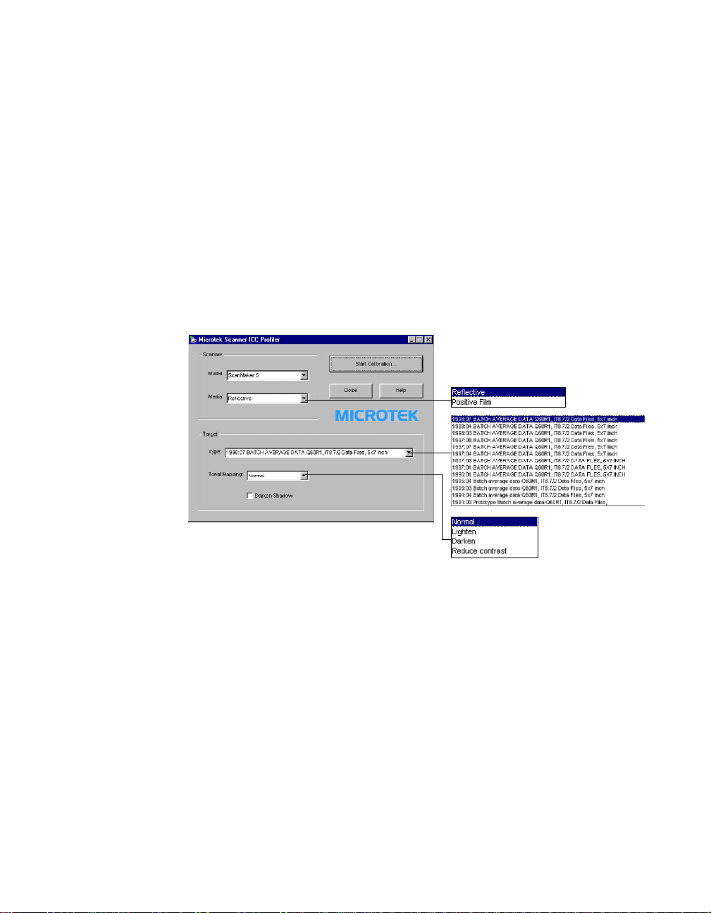
Do the following:
C
A. Select the media type.
Select Reflective option to calibrate for reflective mode, or select
Positive Film option to calibrate for transparent mode.
B. Select the target type.
Select the option that matches your target’s type and date code. For
example, if you use Q-60R1 with 1996.01 date code, you have to select
the “1996.01 BATCH AVERAGE DATA Q60R1, IT8.7/2 DATA FILES,
5x7 INCH” option.
2-6 Microtek Scanner ICC Profiler User’s Manual
Page 13

As shown in the following figure, at the bottom-left of the target, you
can find the date code of the target, and near the bottom center (Q60E1 and Q-60E3), or the bottom-right (Q-60R1), you can read the
target type.
Date code
C. Click on the Start Calibrate button.
Initial preview
Target type
Click the “Start Calibrate…”, the calibration window displays, and an
initial preview is performed.
Calibration dialog
box for Windows
Scan button
Preview button
Using Microtek Scanner ICC Profiler 2-7
Page 14

Step 1: Scan target image
When Preview is done, the “Calibration Procedure Step-1: Scan target image”
displays the detected target, and telling you the next step.
To select the target image, move the pointer (now a crossbar) to the preview
image, and draw a frame enclosing the target image. When you release the
mouse, the scan frame is enclosed in dotted marquee.
Scan frame is enclosed
in dotted marquee.
To resize the selection, move the cursor to any corner of the frame; the pointer
is changed to a double-headed arrow. With holding down the mouse, and drag
to form a new selection, then release the mouse.
When target image is selected, click the “Scan” button to scan the target.
Step 2: Align target registration marks
2-8 Microtek Scanner ICC Profiler User’s Manual
Page 15
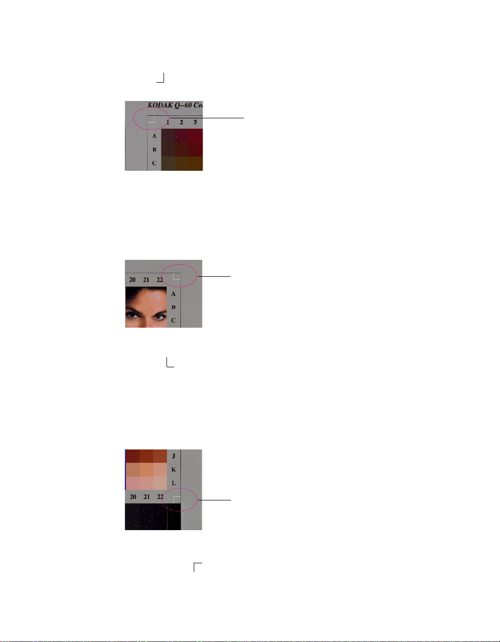
Align upper-left registration mark
Move the cursor into the target image area; the pointer will change to a flipped L
mark (“ ”). Align the cursor with the small upper-left registration mark.
Upper left registration mark
Align upper-right registration mark
After the upper left mark is aligned, the upper right part of the target image is
displayed, the instruction dialog box prompts to align the upper right
registration mark.
Upper right registration mark
Move the cursor into the target image area; the pointer will change to a normal
L mark (“ ”). Align the cursor with the small upper-right registration mark.
Align bottom-right registration mark
After the upper right mark is aligned, the lower right part of the target image is
displayed, the instruction dialog box prompts to align the bottom right
registration mark.
Bottom-right registration mark
Move the cursor into the target image area; the pointer will change to a vertically
flipped L mark (“ ”). Align the cursor with the small bottom-right registration
mark.
Using Microtek Scanner ICC Profiler 2-9
Page 16

Step 3: Create a profile
Now, the instruction dialog prompts you to click the “Calibrate” button.
Click the “Calibrate” button. This only takes a few moments. When the process
finished, a message gives you the results.
Calibrate
button
• If the process was successful, a custom scanner ICC profile is saved automatically to the system’s profile directory. Exit Scanner ICC Profiler now, and
use the new scanner profile with ScanWizard Pro to scan excellent color
images.
• If the process failed, you’ll need to re-scan the target image, repeat the
calibration procedure. Make sure the registration marks are aligned properly.
2-10 Microtek Scanner ICC Profiler User’s Manual
Page 17
3
Reference
This chapter describes the respective features of the Microtek ICC Scanner Profiler.
All the features are covered in the Main window and Calibration window.
The Main Window
The main window provides a system menu and a few controls, allowing you to
manipulate the calibration process.
Controls
Scanner Model
Lets you to select the scanner for calibration.
Media
This option lets you to select the media type for calibration. If the scanner does
not support particular media, that media option is removed from the list.
Target Type
Lets you to select the Target Description File (TDF) that matches with your Q60 (or IT8) calibration target being used for calibration.
Note: Target Description File (TDF) contains colorimetric measurements of the Q-60
target. Each lot of Q-60 target contains unique colorimetric data. Scanner ICC Profiler
evaluates the scanned RGB data of the Q-60 target, and corresponds it to the
colorimetric data inside the TDF, then creates an ICC color profile – a characterization
of how your scanner sees color.
Reference 3-1
Page 18

Tonal Mapping
Lets you to select the tonal mapping option which is used to control the tonal
reproduction curve of the profile.
• Normal – Slightly brightens the highlights, also darken the shadows
• Lighten – Brightens the highlights, also lighten the image overall
• Darken – Darkens the shadows without changing the highlights
• Reduce Contrast – Captures as much of the original as possible (Note:
Recommended for CMYK color separation.)
Darken Shadow
Lets you compensate for artifacts introduced by scanners that have problems
with shadow. Enable this option if you want to –
• lose detail in the shadow areas of an image,
• make the shadow areas of an image darker, or
• reduce the appearance of noise in the shadow areas.
Start Calibration
This button starts the calibration process by displaying the calibration window,
and guide you through the process step-by-step to create a customized scanner
ICC Profile.
Close
This button allows you to close and exit Scanner ICC Profiler.
Help
This button displays the help window.
3-2 Microtek Scanner ICC Profiler User’s Manual
Page 19

System
Menu
Click here to
show the
System menu
The System menu displays current scanner information, view the SCSI chain
status, and view the About dialog box of Scanner ICC Profiler program.
Get Current Scanner Info
This command provides information of the connected scanner. When you
choose this command, a dialog box appears showing the scanner model, SCSI
ID number, and firmware version.
Scanner Probe
This command displays the scanner’s SCSI devices on the SCSI chain and the
SCSI ID.
To use the SCSI chain feature:
1. Choose the Get SCSI Chain Info command.
The SCSI Chain dialog box appears.
2. If your scanner does not show, make sure your
scanner is connected and turned on, then click
on the Probe button on the SCSI Chain dialog
box.
3. Choose the correct interface card in the card
selection box.
4. Check the numbered box corresponding to the
SCSI ID of your scanner. Click OK to close the
dialog box.
About
This command displays the splash screen of Scanner ICC Profiler, which
includes product logo and software version number.
Reference 3-3
Page 20

Calibration Window (Preview & Scan target image)
Preview
The Preview button scans a low-resolution preview of the whole maximum scan
area.
Preview Area
Status bar
Scan button
Preview button
Note: When the calibration window is brought up, Scanner ICC Profiler performs the
initial preview automatically.
Scan
The Scan button lets you scan your selected color calibration target image.
Preview Area
The preview area is where the preview image appears.
Status Bar
This status bar is used to display progress information when previewing or
scanning (e.g., “Previewing… 17%”).
3-4 Microtek Scanner ICC Profiler User’s Manual
Page 21

Calibration Window (Align target and create profile)
Calibrate
The “Calibrate” button lets you create custom scanner ICC profile. This button
is grayed out until three required registration marks are aligned.
<<Previous Mark
The “<<Previous Mark” button lets you go back one step to align the previous
registration mark. This button is grayed out when the upper-left registration
mark is being aligned.
Next Mark>>
The “Next Mark>>” button lets you go forward one step to align the next
registration mark. This button is grayed out when the next unaligned
registration mark, or the bottom-right registration mark is being aligned. It will
be enabled when the “<<Previous Mark” button is clicked.
Goto Step 1
The “Goto Step 1” button lets you go back to the preview image screen (the
screen of Step 1) to re-scan the target image, and re-start the calibration process.
Show Patches
Click this option to check the sampling area of all color patches. When aligned
properly, the sampling area appears as a green square in the center of most
patches. If any areas fall outside a patch, realign the registration marks by
clicking the “<<Previous Mark” and “>>Next Mark” buttons and re-selecting the
registration marks until the sampling areas are centered.
Close
Click the “Close” button to return to the main screen.
Reference 3-5
Page 22

4
Troubleshooting
1. Scanner ICC Profiler can’t find any scanner.
Solution: Make sure your scanner work with ScanWizard Pro first. If
ScanWizard Pro also can’t find your scanner, refer to the Troubleshooting
Section of your ScanWizard Pro User's Manual.
2. Scanner not supported.
Solution: Scanner ICC Profiler supports scanner models that are supported
by ScanWizard Pro only.
3. Can’t find proper target description file (TDF) that matches the target
type and the date code.
Solution: You must use the target that came with your Microtek’s scanner. If
you do so, but still cannot find proper TDF in Scanner ICC Profiler, contact
your local Microtek dealer for obtaining an updated version of Scanner ICC
Profiler.
4. Using the new calibrated profile, color images in ScanWizard Pro looks
washed out with little detail in highlight areas.
Solution: You might have incidentally used “Lighten” tonal mapping option
to calibrate your scanner. Recalibrate your scanner with “Normal” Tonal
Mapping option.
5. Using the new calibrated profile, color images in ScanWizard Pro looks
too dark with little detail in shadow areas.
Solution: You might have incidentally used “Darken” tonal mapping option,
or “Darken Shadow” option to calibrate your scanner. Recalibrate your
scanner with “Normal” Tonal Mapping option, and disable the “Darken
Shadow” option.
6. Using the new calibrated profile, color images in ScanWizard Pro looks
messed up or abnormal.
Solution: During calibration, the target registration marks might not be
aligned properly. Recalibrate your scanner by aligning the registration marks
carefully. For details of how to align each registration mark, refer to the
“Calibration procedure” section in the help file or user manual.
Troubleshooting 4-1
Page 23

7. Using the new calibrated profile, the color images in ScanWizard Pro has
an inaccurate look.
Solution: The target might not be placed as recommended, or wrong target
description file (TDF) was chosen. Recalibrate your scanner by placing the
calibration target properly, then choose the proper TDF that matches with
your target type and date code.
8. Can’t open the help file.
Solution: Microsoft Internet Explorer 4.0 or above is needed to access
Scanner ICC Profiler’s help file.
4-2 Microtek Scanner ICC Profiler User’s Manual
 Loading...