

Page 1

How to use
Microtek Scanner ICC Profiler (MSP) For
ScanMaker 8700
The Microtek Scanner ICC (International Colour Consortium) Profiler is a scanner calibration and profiling
utility program exclusively designed for Microtek scanners, including the ScanMaker 8700. The profiler lets
you calibrate the accurate color attributes of your scanner and create an ICC color profile customized and
tailored particularly for the scanner you are using under ScanWizard Pro.
To keep the colors in your scanner consistent over time, it is recommended that you calibrate using the
Scanner ICC Profiler on a regular basis. Professional photographers, graphic designers or others who
require extremely precise color may wish to calibrate the scanner every time it is used.
Calibration kit
Y our MSP utility program is included in the same CD-ROM that contains the ScanW izar d Pro software. Two
industry-standard Kodak color targets, Reflective (Kodak Q-60R1, size 5" x 7") and Transparency (Kodak
Q-60E1, size 4" x 5") for calibration are included in the scanner accessories package.
Note:
The calibration targets are very delicate and must be handled car efully as follows:
••
• Gently remove targets from their respective protective sleeve and avoid touching the target image
••
surface.
••
• When not in use, keep targets in their respective sleeves and away from light and heat.
••
1
Insert the ScanWizard Pro CD-ROM into your CD-ROM drive. After selecting the language of your choice,
click on the ICC Profiler icon, then follow the on-line instruction to completely install the program.
Note:
will not work.
MSP installation
The ScanWizard Pro program should be alr eady installed in your system befor e installing MSP. Otherwise, MSP
I49-003206 A, May 2001 (E)Copyright © 2001 Microtek International, Inc. http://www.microtek.com
Page 2
2
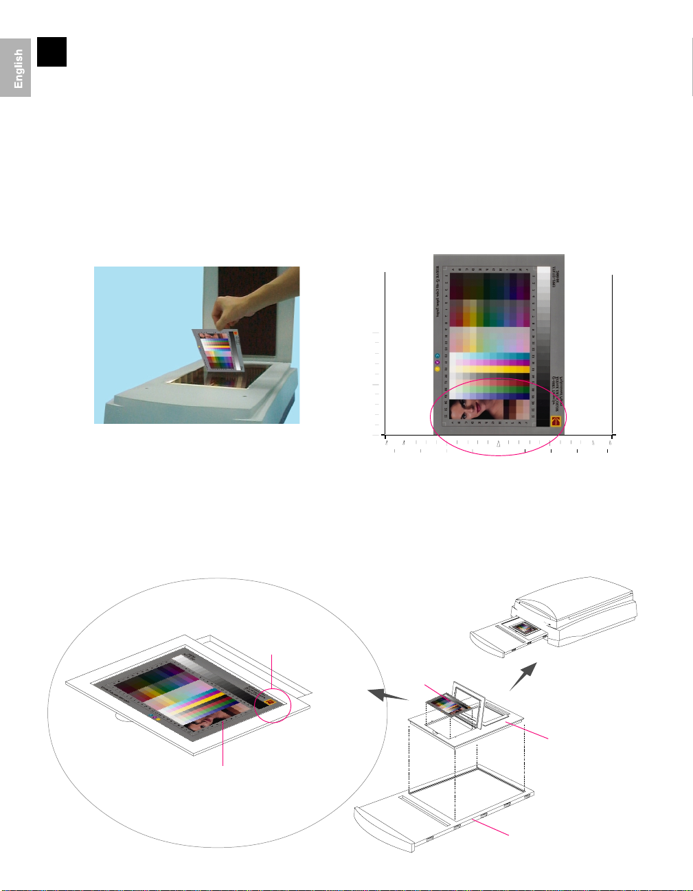
Positioning of target on scanner
Reflective target
The proper positioning of the reflective color target on the ScanMaker 8700 is important for successful
calibration. Follow the steps below:
1. Place the target on the glass surface of the scanner bed, making sure that the right side of the target (with
the woman’s portrait) is positioned toward the scanner front panel (see figure below) and has its edge firmly
aligned against the scanner top ruler.
2. Using the scanner top ruler as point of reference, adjust the flipped target position so that it is horizontally
at the center of the glass.
Transparency target
10
5
0
B5A4 B5mmA4
4
Position the flipped target at the center of the glass.
5
2
"Face Down
Position!"
0
5
2 4
1. Flip and place the transparency target in the 4" x 5" Film Template. Orientation of the target is critical. Make
sure that the woman’s portrait is at the right side of the scanner (where the Kodak logo is positioned at the
upper-right corner).
2. Place the 4" x 5" Film T emplate in the Main Staging Template, then put this assembly in the transparency tray
of the scanner.
Kodak© logo is
positioned at the
upper-right corner
Cible transparente
Make sure that the woman’s
portrait lies towards the right
side of the scanner
4” x 5” Film Template
Main Staging Template
2
Page 3

3
1. With the target properly positioned in the scanner, turn
Calibration setup
on your scanner and let it warm up for about five
minutes.
A
B
F
2. Launch the Scanner ICC Profiler calibration utility.
When the main MSP dialog window appears, do the
following:
A Choose the model of scanner you are currently
calibrating.
B Choose the proper target media. If you are
calibrating reflectivetarget, select Reflective. Otherwise, select Positive.
C Select the date code and target type from the drop down list that
match with your target. Y ou can verify this information by looking at
the left and right corners of the target bottom margin.
::
Note
: If you are unable to find the tar get type with date code that matches with the target you ar e using, find the
::
T ar get Profile CD that came with your scanner.
For Macintosh, run Macsetup program on the CD.
For Windows, run Winsetup.exe on the CD. Then restart MSP. The target type with your date code should now be
available from the selection list.
TT
D Set
onal Mappingonal Mapping
T
onal Mapping. T h i s o p tion lets you select the way the tonal reproduction curve of the pr ofile should
TT
onal Mappingonal Mapping
be controlled.
NormalNormal
•
Normal: Slightly brightens the highlights but also darkens the shadows.
NormalNormal
LightenLighten
•
Lighten: B ri gh te ns th e h ig hlights and also lightens the overall image.
LightenLighten
DarkenDarken
•
Darken: Darkens the shadows without changing the highlights.
DarkenDarken
Reduce ContrastReduce Contrast
•
Reduce Contrast: (Default and recommended setting if you are not certain of your need.) Captures
Reduce ContrastReduce Contrast
as much of the original as possible. Recommended for CMYK color separation.
C
D
E
Date code and target type information
TT
Note:
You may cr eate several profiles with dif ferent
unique filename for each profile.
E Check
F When all the settings are done, click on the
Darken ShadowDarken Shadow
Darken Shadow check box if you want to compensate the artifacts introduced by the scanner
Darken ShadowDarken Shadow
indicating problems with the shadow portion of the image. When enabled, this option will -
• Minimize the details in the shadow areas of the image
• Make the shadow areas of an image darker; or
• Reduce the appearance of noise in the shadow areas.
Note:
You may cr eate two different pr ofiles, one with
disabled, and another enabled. Just remember to assign a unique filename
for each of the profile.
The calibration window will appear, and an initial preview of the
target is performed.
onal Mapping onal Mapping
T
onal Mapping mapping setting. Just r emember to assign a
TT
onal Mapping onal Mapping
Darken ShadowDarken Shadow
Darken Shadow
Darken ShadowDarken Shadow
Start ProfilingStart Profiling
Start Profiling button.
Start ProfilingStart Profiling
3
Page 4

4
After the Preview, follow the sequential messages that appear for
instructions on steps to take to complete calibration and create a profile
for your scanner.
Step 1: Scan target image
Select the whole IT8 target by dragging a frame over it.
Then click on “Scan” button to scan the target image.
Step 2: Align target registration marks
Calibration and profiling processes
A. Upper-left registration mark
Move the cursor into the target image
area; the pointer will change to a
horizontally flipped L mark (“ ”). Align
the cursor with the small upper-left
registration mark.
Step 3: Create profile
Click “Create Profile” button to create a scanner ICC profile. At the end of
the profiling process the dialog box appears. Enter filename and profile
description as appropriate.
Note:
If the process fails, you will need to r escan the target image and repeat the
calibration procedure. Make sur e the r egistration marks are aligned pr operly, then
click the Create Profile button again to cr eate your scanner pr ofile.
B. Upper-right registration mark C. Bottom-right registration mark
After the upper left mark is aligned, the
upper right part of the target image is
displayed, and an instruction dialog box
prompts you to align the upper right
registration mark.
Move the cursor into the target image
area; the pointer will change to a normal
L mark (“ ”). Align the cursor with the
small upper-right registration mark.
After the upper right mark is aligned,
the lower right part of the target image
is displayed, and an instruction dialog
box prompts you to align the bottomright registration mark.
Move the cursor into the target image
area; the pointer will change to a
vertically flipped L mark (“ ”). Align the
cursor with the small bottom-right
registration mark.
5
1. Launch ScanWizard Pro.
2. Click the
3. From
Loading a profile
Material Selection Material Selection
Material Selection icon to select scan material.
Material Selection Material Selection
Settings Settings
Settings window , click on the
Settings Settings
one of the scanner profiles you have just created.
Scanner PrScanner Pr
Scanner Pr
Scanner PrScanner Pr
ofileofile
ofile li s t box and select
ofileofile
4
 Loading...