

Page
1
Microsemi
查询TGL41-180A供应商
TGL41-6.8 thru TGL41-200CA
500 Watt Transient Voltage Suppressor
SCOTTSDALE DIVISION
This series of 500 W Transient Voltage Suppressors (TVSs) provides the
highest level of Peak Pulse Power (PPP) in the industry for the DO-213AB
size MELF package. These PPP levels offer protection from switching
transients, induced RF, secondary lightning, as well as ESD or EFT where
these devices are also compliant to IEC61000-4-2 and IEC61000-4-4. In
addition to unidirectional TVS configurations, this series also offers
bidirectional options with C or CA suffix. Its configuration in a MELF
package prevents lead damage to terminals and also reduces inductive
parasitics for minimal transient voltage overshoots.
IMPORTANT: For the most current data, consult MICROSEMI’s website: http://www.microsemi.com
• Economical series for 500 Watt Surface Mount
transient voltage suppressor.
• Available in Both Unidirectional and Bidirectional
Construction. Bidirectional has a C or CA suffix.
• 6.8 to 200 Volts Available.
• 500 Watts Peak Power Dissipation.
• Fast Response Time: Subnanosecond Response
(Unipolar) or 5.0 ns (Bipolar).
• Plastic package has flame retardant epoxy meeting
UL94V-0
FEATURES
• Peak Pulse Power Dissipation (PPP) - 500 W (Note
• Peak Forward Surge Current (I
• Peak Pulse Current (IPP) at 10/1000 µs waveform -
• Steady-State Power Dissipation, P
• Operating and Storage temperatures, TOP, T
• Thermal Resistance junction to end cap (R
MAXIMUM RATINGS @ 25oC*
1 & 5).
see Table 1 (Note 1)
2, 4)
(-55oC to +150oC)
15oC/W
* Unless otherwise specified.
NOTES: 1. Non-repetitive current pulse, per Figure 3 and derated above TA = 25oC per Figure 2.
2. Mounted on 4.0 mm2 copper pads to each terminal. (See Figure 3)
3. 8.3 ms single half-sine wave duty cycle = 4 pulses per minute max. Peak forward voltage at 40 A is 3.5 volts (unipolar only)
4. Derate linearly above 100oC to zero at 150oC for dc steady-state power. Also see Figure 2 for transient derating.
5. Peak pulse current waveform is 10/1000 µs, with maximum duty cycle of 0.01%. (See Figure 4)
DESCRIPTION
) - 40 A (Note 3)
FSM
- 3.0W (Note
(AV)
STG
?
JEC
–
) –
APPLICATIONS / BENEFITS
• For Surface Mount Applications
• Protection from switching transients, induced
RF, secondary lightning, as well as ESD, and
EFT per IEC 61000-4-2 and IEC 6100-4-4
• Very low inductive parasitics with minimal
Ldi/dt voltage overshoots for fast-rise-time
transients
• Robust package for pick-and-place handling
MECHANICAL AND PACKAGING
• Molded epoxy package meets UL94V-0
• End-Cap terminals solderable per MIL-STD-750,
Method 2026 (max 260oC for 10 seconds.
• Polarity is indicated by cathode band. Bidirectional
devices have no polarity band.
• Body marked with P/N without TGL41 prefix.
• Weight: 0.06 grams (approximate)
• Tape and Reel packaging per EIA-481-2 with 12
mm tape with 5000 per 13 inch reel.
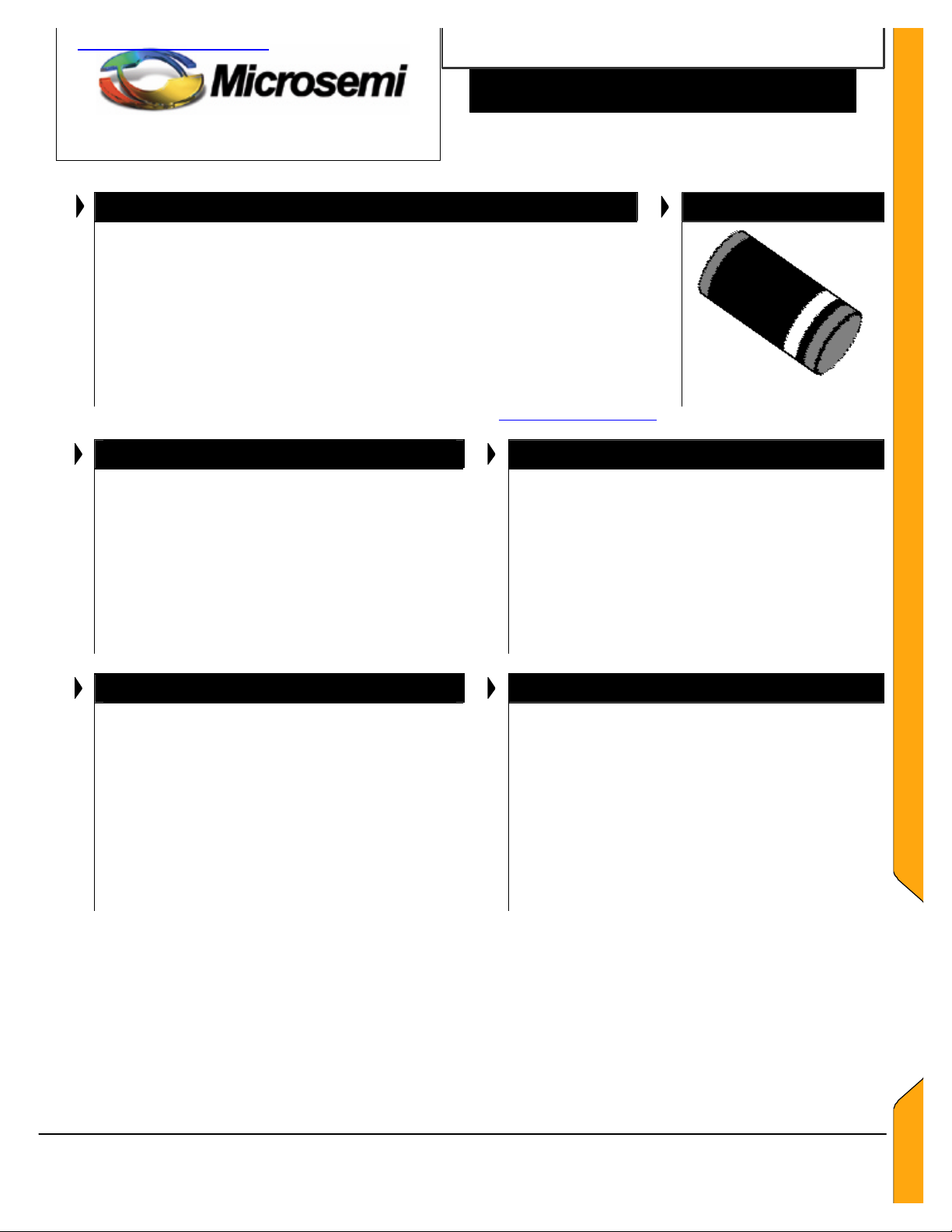
APPEARANCE
WWW.
.COM
DO-213AB
TGL41-6.8 thru 200CA
Copyright 2003
01-29-2003 REV A
Microsemi
Scottsdale Division
8700 E. Thomas Rd. PO Box 1390, Scottsdale, AZ 85252 USA, (480) 941-6300, Fax: (480) 947-1503

Page
2
Microsemi
SCOTTSDALE DIVISION
TGL41-6.8 thru TGL41-200CA
500 Watt Transient Voltage Suppressor
Copyright 2003
01-29-2003 REV A
ELECTRICAL CHARACTERISTICS @ 25oC
MICROSEMI
PART
NUMBER
V V V mADC V
TGL41-6.8
TGL41-6.8A
TGL41-7.5
TGL41-7.5A
TGL41-8.2
TGL41-8.2A
TGL41-9.1
TGL41-9.1A
TGL41-10
TGL41-10A
TGL41-11
TGL41-11A
TGL41-12
TGL41-12A
TGL41-13
TGL41-13A
TGL41-15
TGL41-15A
TGL41-16
TGL41-16A
TGL41-18
TGL41-18A
TGL41-20
TGL41-20A
TGL41-22
TGL41-22A
TGL41-24
TGL41-24A
TGL41-27
TGL41-27A
TGL41-30
TGL41-30A
TGL41-33
TGL41-33A
TGL41-36
TGL41-36A
TGL41-39
TGL41-39A
TGL41-43
TGL41-43A
TGL41-47
TGL41-47A
TGL41-51
TGL41-51A
TGL41-56
TGL41-56A
TGL41-62
TGL41-62A
TGL41-68
TGL41-68A
TGL41-75
TGL41-75A
TGL41-82
TGL41-82A
TGL41-91
TGL41-91A
8700 E. Thomas Rd. PO Box 1390, Scottsdale, AZ 85252 USA, (480) 941-6300, Fax: (480) 947-1503
BREAKDOWN
VOLTAGE
V
MIN. NOM. MAX.
6.12
6.45
6.75
7.13
7.38
7.79
8.19
8.65
9.0
9.5
9.9
10.5
10.8
11.4
11.7
12.4
13.5
14.3
14.4
15.2
16.2
17.1
18
19
19.8
20.9
21.6
22.8
24.3
25.7
27
28.5
29.7
31.4
32.4
34.2
35.1
37.1
38.7
40.9
42.3
44.7
45.9
48.5
50.4
53.2
55.8
58.9
61.2
64.6
67.5
71.3
73.8
77.9
81.9
86.5
(BR)
6.8
6.8
7.5
7.5
8.2
8.2
9.1
9.1
10
10
11
11
12
12
13
13
15
15
16
16
18
18
20
20
22
22
24
24
27
27
30
30
33
33
36
36
39
39
43
43
47
47
51
51
56
56
62
62
68
68
75
75
82
82
91
91
7.48
7.14
8.25
7.88
9.02
8.61
10
9.55
11
10.5
12.1
11.6
13.2
12.6
14.3
13.7
16.5
15.8
17.6
16.8
19.8
18.9
22
21
24.2
23.1
26.4
25.2
29.7
28.4
33
31.5
36.3
34.7
39.6
37.8
42.9
41
47.3
45.2
51.7
49.4
56.1
53.6
61.6
58.8
68.2
65.1
74.8
71.4
82.5
78.8
90.2
86.1
100
95.5
TEST
CURRENT
I
(BR)
10
10
10
10
10
10
1
1
1
1
1
1
1
1
1
1
1
1
1
1
1
1
1
1
1
1
1
1
1
1
1
1
1
1
1
1
1
1
1
1
1
1
1
1
1
1
1
1
1
1
1
1
1
1
1
1
RATED
STAND-OFF
VOLTAGE
VWM
5.5
5.8
6.05
6.4
6.63
7.02
7.37
7.78
8.1
8.55
8.92
9.4
9.72
10.2
10.5
11.1
12.1
12.8
12.9
13.6
14.5
15.3
16.2
17.1
17.8
18.8
19.4
20.5
21.8
23.1
24.3
25.6
26.8
28.2
29.1
30.8
31.6
33.3
34.8
36.8
38.1
40.2
41.3
43.6
45.4
47.8
50.2
53
55.1
58.1
60.7
64.1
66.4
70.1
73.7
77.8
Microsemi
Scottsdale Division
MAX
REVERSE
LEAKAGE
CURRENT
ID @ VWM
µA
1000
1000
500
500
200
200
50
50
10
10
5
5
5
5
5
5
5
5
5
5
5
5
5
5
5
5
5
5
5
5
5
5
5
5
5
5
5
5
5
5
5
5
5
5
5
5
5
5
5
5
5
5
5
5
5
5
MAX.
CLAMPING
VOLTAGE
VC @ IPP
V A %/oC
10.8
10.5
11.7
11.3
12.5
12.1
13.8
13.4
15
14.5
16.2
15.6
17.3
16.7
19
18.2
22
21.2
23.5
22.5
26.5
25.2
29.1
27.7
31.9
30.6
34.7
33.2
39.1
37.5
43.5
41.4
47.7
45.7
52
49.9
56.4
53.9
61.9
59.3
67.8
64.8
73.5
70.1
80.5
77
89
85
98
92
108
103
118
113
131
125
MAX.
PEAK
PULSE
CURRENT
IPP
46.3
47.6
42.7
44.2
40.0
41.3
36.2
37.3
33.3
34.5
30.9
32.1
28.9
29.9
26.3
27.5
22.7
23.6
21.3
22.2
18.5
19.8
17.2
18.1
15.7
16.3
14.4
15.1
12.8
13.3
11.5
12.1
10.5
10.9
9.6
10.0
8.9
9.3
8.1
8.4
7.4
7.7
6.8
7.1
6.2
6.5
5.6
5.9
5.1
5.4
4.6
4.9
4.2
4.4
3.8
4.0
MAX.
TEMP
COEFFICI
ENT
α
V(BR)
.057
.057
.061
.061
.065
.065
.068
.068
.073
.073
.075
.075
.078
.078
.081
.081
.084
.084
.086
.086
.088
.088
.090
.090
.092
.092
.094
.094
.096
.096
.097
.097
.098
.098
.099
.099
.100
.100
.101
.101
.101
.101
.102
.102
.103
.103
.104
.104
.104
.104
.105
.105
.105
.105
.106
.106
WWW.
.COM
TGL41-6.8 thru 200CA

Page
3
Microsemi
SCOTTSDALE DIVISION
TC = 25oC
P
P
TGL41-6.8 thru TGL41-200CA
500 Watt Transient Voltage Suppressor
MICROSEMI
PART
NUMBER
BREAKDOWN
VOLTAGE
V
(BR)
MIN. NOM. MAX.
TEST
CURRENT
I
(BR)
RATED
STAND-OFF
VOLTAGE
VWM
V V V mA V
TGL41-100
TGL41-100A
TGL41-110
TGL41-110A
TGL41-120
TGL41-120A
TGL41-130
TGL41-130A
TGL41-150
TGL41-150A
TGL41-160
TGL41-160A
TGL41-170
TGL41-170A
TGL41-180
TGL41-180A
TGL41-200
TGL41-200A
90
95
99
105
108
114
117
124
135
143
144
152
153
161
162
171
180
190
100
100
110
110
120
120
130
130
150
150
160
160
170
170
180
180
200
200
110
105
121
116
132
126
143
137
165
158
176
168
187
179
198
189
220
210
1
1
1
1
1
1
1
1
1
1
1
1
1
1
1
1
1
1
81
85.5
89.2
94
97.2
102
105
111
121
128
130
136
138
145
146
154
162
171
MAX
REVERSE
LEAKAGE
CURRENT
ID @ VWM
µA
5
5
5
5
5
5
5
5
5
5
5
5
5
5
5
5
5
5
MAX.
CLAMPING
VOLTAGE
VC @ IPP
V A %/oC
144
137
158
152
173
165
187
179
215
207
230
219
244
234
258
246
287
274
For Bidirectional construction, indicate a C or CA suffix after part number. Capacitance will be ½ that shown in Fig 3.
Forward Voltage (Vf) @ 40 amps peak 8.3 ms half-sine wave equal to 3.5 volts max (For Unidirectional only).
Symbol Definition Symbol Definition
VWM Rated Stand-Off voltage V
IPP Peak Pulse Current I
SYMBOLS & DEFINITIONS
Breakdown Voltage
(BR)
Breakdown Current
(BR)
PPP Peak Pulse Power ID Standby Current
OUTLINE AND CIRCUIT
MAX.
PEAK
PULSE
CURRENT
IPP
3.5
3.6
3.2
3.3
2.9
3.0
2.7
2.8
2.3
2.4
2.2
2.3
2.0
2.1
1.9
2.0
1.7
1.8
MAX.
TEMP
COEFFICI
ENT
α
V(BR)
.106
.106
.107
.107
.107
.107
.107
.107
.108
.108
.108
.108
.108
.108
.108
.108
.108
.108
WWW.
.COM
0.1 2.0 0.5 1.0 2.0 5.0 10 20 50 100 200 1000 10,000
Peak Pulse Power vs. Pulse Width
Copyright 2003
01-29-2003 REV A
30
20
10
7.0
5.0
3.0
2.0
1.0
0.7
0.5
– Peak Pulse Power – kW
PP
0.3
0.2
) or
PP
C rating
o
) in Percentage of
PP
25
Peak Pulse Power (
Current (I
End Cap Temperature oC
tw – Microseconds FIGURE 2
FIGURE 1 Derating Curve
Microsemi
8700 E. Thomas Rd. PO Box 1390, Scottsdale, AZ 85252 USA, (480) 941-6300, Fax: (480) 947-1503
Scottsdale Division
TGL41-6.8 thru 200CA

Page
4
Microsemi
SCOTTSDALE DIVISION
Percentage of
IPP C – Capacitance
-
Picofarads
Pulse Current (I
) in
TGL41-6.8 thru TGL41-200CA
500 Watt Transient Voltage Suppressor
WWW.
Percentage of IPP –
Amperes vs. Time (t) Milliseconds
Milliseconds V
P
- Breakdown Voltage – Volts
(BR)
FIGURE 3 FIGURE 4
Pulse Waveform for Exponential Surge Typical Capacitance vs. Breakdown Voltage (Unidirectional only)
Bidirectional Suffix C devices are ½ that shown.
DIMENSIONS AND LAYOUT
.COM
MELF
DO-213AB
Copyright 2003
01-29-2003 REV A
MILLIMETERS INCHES
DIM
MIN MAX MIN MAX
A 2.39 2.66 0.094 0.102
B 4.80 5.20 0.189 0.205
C 0.41 0.55 0.016 0.022
8700 E. Thomas Rd. PO Box 1390, Scottsdale, AZ 85252 USA, (480) 941-6300, Fax: (480) 947-1503
TGL41-6.8 thru 200CA
Microsemi
Scottsdale Division
 Loading...